Article

Experimental and Numerical Study on Progressive Collapse of the Midcolumn in a Glulam Timber Frame Exposed to Fire

College of Civil Engineering, Nanjing Tech University, Nanjing 211816, China
*
Author to whom correspondence should be addressed.
Fire 2023, 6(10), 374; https://doi.org/10.3390/fire6100374
Submission received: 31 July 2023 / Revised: 23 August 2023 / Accepted: 29 August 2023 / Published: 27 September 2023

Abstract

:
This paper presents experimental and numerical investigations on the progressive collapse behavior of a two-story glulam frame when the middle column is exposed to ISO834 standard fire. The stress characteristics, temperature distributions, and deformation relationship curves of the bottom middle column after a fire are obtained. The collapse resistance performance and the mechanism of the glulam structure under local fire are studied in combination with the failure mode of the frame. The experimental results show that the failure time of the middle column in fire is 16.8 min, and the time to determine the progressive collapse of the structure is 17.17 min when the rotation angle exceeds the limit. The structure can remain stable for some time after the failure of the fire column, but as the fire continues to spread, the structure will collapse further. In addition, a temperature-field analysis model with the grid element type of DC3D8 and a structural field analysis model with the grid element type of C3D8R was established by using ABAQUS software under the experimental conditions. The numerical simulation is carried out by means of thermal–mechanical sequential coupling. The numerical simulation results show that the temperature of the beam end rose to more than 300 °C in about 15 min although it was not directly exposed to fire. The temperature of the whole connector at the pillar foot in the bottom column reached more than 700 °C when the fire time reached 60 min. The numerical simulation results agree well with the experimental results. The analysis results show that, in the failure process of the fire column, the junction of beam ends begins to produce stretching force to form a catenary effect. As the fire time increases, the catenary effect eventually fails. The stretching force at the beam end rapidly decreases and withdraws from the work, causing the progressive collapse of the frame.

1. Introduction

In the context of the continuous development of industrialization in the world today, the emission of polluting waste gas has seriously hindered the progress of global sustainable development. As a renewable and recyclable natural resource, wood has the characteristics of being green, energy saving, and environmentally friendly. At the same time, it can provide a comfortable living environment for human beings [1]. As a country where traditional architecture uses wooden structures, China began to use wooden structures as early as 6000 years ago, and each dynasty and generation has retained wooden structures, such as Nanchan Temple Hall, Sakya Pagoda, Beijing Palace Museum, Yingxian Wooden Pagoda, and so on [2]. As current trends in the construction industry are moving towards improving environmental impact and fire safety, changes to building materials are constantly being introduced [3]. With the advancement of social industrialization, glulam timber was first invented in the 1810s. It has become a common engineering wood in modern wood structure buildings. It has the characteristics of free design, high stability, easy handling, good seismic resistance, and high industrialization, which marks a new beginning in the development of the modern wood structure [4]. Compared with modern building materials, such as steel and concrete, wood is the only green building material that contains renewable, reusable, and biodegradable properties. Buildings constructed from engineered timber are becoming more prevalent globally as building designers, owners, and architects realize the sustainability opportunities with timber construction and the overall aesthetic of a completed timber building [5]. Fire safety is an important issue in all types of construction, especially in wooden-frame buildings [6]. However, compared with noncombustible building materials, such as reinforced concrete or steel, the flammability of wood and the fire incidents of timber structures in the past lead to people generally believing that fire safety limits the development of timber structures. When the structure meets fire, the column is an important load-bearing member in the timber structure, and its fire-resistance performance is crucial to the collapse resistance of the whole structure. The destruction of the column may further cause the destruction of the surrounding restraint members connected to it and even lead to the progressive collapse of the whole structure [7].
Most of the existing studies on the fire performance of timber structures focus on determining the effective carbonization rate [8,9,10,11,12,13,14,15,16,17]. A charring layer formed after high-temperature pyrolysis of wood can prevent heat transfer to the interior of the wood. The current wood-structure design guidelines focus on specifying a fixed carbonization rate and assume that there is an additional fixed “zero strength” layer to solve the reduction of mechanical properties of heated wood after carbonization. Wood usually undergoes three main pyrolysis stages: dehydration and very slow pyrolysis below 200 °C, pyrolysis at up to 300 °C begins to form a carbonized layer, and rapid pyrolysis above 300 °C, resulting in mass loss, strength, and mechanical properties decreased. The mechanical properties of the core wood will decrease with the increase in temperature. When the outer layer of the wood is carbonized, the temperature rise rate of the core wood is slowed down, thereby protecting the mechanical properties of the core wood [18]. Xu et al. [19] conducted experiments to compare the burning and carbonization properties of five common building timbers. The results showed that the charring rate increases with the increase of heat flux and the charring speed decreases with the increase of fire time. The reason is the thermal conductivity of the charring layer is much lower than unburned wood, which protects the core wood from the influence of high temperature to a certain extent, thus slowing down the rate of heat penetration to the interior of the wood. Kinjo et al. [20] discussed the fire resistance of glulam timber beams from two aspects of deflection characteristics and fire-resistance limit through the fire test of glulam timber beams under constant load conditions. The results showed that the carbonization rate decreases in the cooling stage and the deflection increases with the increase of section temperature. The failure mode is bending failure, which is mainly due to the tensile failure of the bottom lamination of the beam. Fonseca and Gomes [21] analyzed the heat conducted by the dowel pin inside the connection, and the steel plate and its effect on the wood. According to the results, it can be assumed that the temperature evolution is due to the geometry of the connection, the dowel pin or plate position, and the glulam density. Inside the wood element, the temperature remains lower, and, externally, a charred depth is developed when the target temperature of 300 °C is reached; in the vicinity of the dowel pin or the steel plate, a burned wood depth is indirectly formed. The rate of the charred layer is not constant throughout the entire fire exposure. Wiesner and Bisby [22] reviewed and evaluated the existing data and methods for the fire-resistance design of wood laminated components. The historical data of fire-resistance tests were given and compared with the existing design methods. The results showed that the existing methods can reasonably predict the fire resistance of glued laminated columns under standard fire (the mean absolute error is 22%). Zhang et al. conducted a series of fire-resistance studies on the levels of timber structural members (timber beams, timber columns) [23,24,25,26,27,28,29], connection nodes [30,31], and beam–column timber frames [32]. A comprehensive understanding of the influence of member section size, load level, and fire protection on the fire-resistance limit of timber structures is obtained.
At present, the studies on the progressive collapse of structures are mostly based on beam–column substructure, performance test of the joint, and numerical simulation. Mpidi Bita et al. [33,34] evaluated the structural performance of the building after removing the inner bottom bearing wall and showed that the building was prone to disproportionate collapse. Mpidi Bita et al. also made numerical studies on a 12-story CLT building [35] and a 9-story flat CLT building [36]. As for the results, a high probability of a structural disproportional collapse was obtained. The structural response of a continuous two-span and discontinuous floor system with traditional and new connection details after the removal of the inner wall was tested, emphasizing the need for new connection details to trigger the collapse resistance mechanism [37]. Petrycki and Salem [38] conducted an experimental study on the monotonic loading performance of eight groups of glulam timber beam-to-column bolted connections under column-moving conditions. The results showed that, compared with the unreinforced connection, the bearing capacity of the self-tapping screw-reinforced plywood connection is significantly improved, and the multiple is between 1.30 and 2.4. Eva’s research [39] showed that the most common failures of timber collapse occur in beam–column and truss support systems.
In studies on the fire collapse of timber structures, Bedon and Fragiacomo [40] studied the inplane compressive performance of timber walls under fire through full-scale standard fire tests and finite element numerical simulations. It was proven that the additional thermal insulation layer on the exposed wall surface has a significant fire spread delay effect, which can prevent the premature collapse of the structure caused by the combined action of thermal and mechanical loads. Jessop et al. [41] conducted a natural fire test to assess the fire resistance of a light wood-frame house subjected to lateral loads. The results showed that the bottom chord of the roof truss was broken after the gypsum ceiling collapsed, and the firewall lost its lateral stability, causing the progressive collapse of the structure. Matthew and Andrew [42] performed experimental and numerical studies on the catenary collapse-resistant capacity of steel–wood composite structures by implanting smaller steel sections into the beam–column members to improve the ductility of the structural system. The results showed that the average time to bear the applied tension under standard fire increases by 34.28% after adding steel bars to the wood members. The above research shows that when the fire-exposed column of the frame is the side column or the corner column under the local fire, most of the frame collapses after the failure of vertical members. When the members exposed to fire are distributed on the symmetry axis of the structure, the part involving the structural connection generally collapses. This kind of working condition is more sudden, and the consequences are more serious. At present, the research on the progressive collapse of structures under fire mainly focuses on concrete-frame structures and steel-frame structures, and there are few experimental studies on timber structures.
In order to take reasonable and economical fire-protection measures for timber structures, it is necessary to have a clear understanding of the high temperature response and failure mechanism of timber structures under fire. The purpose of this research is to explore the failure mechanism and collapse mechanism of multistory and high-rise timber structures, scientifically evaluate the fire resistance of the whole structure, and promote the development and application of the design theory of fire resistance and progressive collapse resistance of multistory and high-rise timber structures under fire to a certain extent. In this paper, the experimental study on the progressive collapse of a glulam timber frame under fire is carried out. The relationship between temperature-field distribution and structural deformation, the failure mode, and the collapse mechanism are obtained. In addition, the numerical model corresponding to the test conditions was established by ABAQUS finite element software to study the influence mechanism of middle column fire on the collapse performance of a glulam timber plane frame.

2. Experimental Recapitulation

2.1. Design of Frame

In order to study the failure mode and collapse mechanism of a timber structure under local fire, a two-story and two-span glulam timber plane frame was designed by referring to GB/T 50329-2012 “Standard for Test Methods of Timber Structures” [43], GB/T 50708-2012 “Technical Code for Glulam Structures” [44], EN 1995-1-2: 2004 Eurocode 5 “Design of Timber Structures–Part 1-2: General–Structural Fire Design.” [45], and the size of the horizontal experimental furnace of Nanjing Gongda Construction Engineering Technology Co., Ltd. (Nanjing, China). The frame height is 840 mm and the column spacing is 1420 mm. The glulam timber beams had a cross section size of 100 mm × 150 mm and a column section size of 150 mm × 150 mm. The specimen dimensions were designed to fit into the furnace. The above are all laminated glulam timber specimens made of Douglas fir. The compression modulus of Douglas fir at different temperatures obtained by the material-property test is shown in Table 1. It can be seen that the compressive modulus of the parallel grain is much larger than that of the transverse grain, and the radial compressive modulus of the transverse grain is larger than the tangential compressive modulus. With the increase in heat-treatment temperature, the compressive modulus of the parallel and transverse textures decreased to varying degrees. Among them, the transverse compressive modulus of Douglas fir is most affected by temperature. The size of the test frame is shown in Figure 1a.
Components of the processing drawings are shown in Figure 1b,c. The number of plate processing is shown in Table 2. The beam–column joints are connected by steel-plate bolts, and the column base is connected with an H-shaped steel ground beam by T-shaped steel-plate bolts. The joint design and the size of the section steel foundation beam are shown in Figure 1d–f and Figure 2. The steel materials used for joint connectors and steel ground beams are Q235, and the bolts are 8.8 grade M10 high strength bolts. The frame is assembled in the test device provided by Nanjing Gongda Construction Engineering Technology Co., Ltd. The process is shown in Figure 3.

2.2. Experimental Scheme

The fire test was carried out in the horizontal test furnace of the JSP-2 channel fire valve ventilation pipe in the fire engineering laboratory of Nanjing Gongda Construction Engineering Technology Co., Ltd. The height of the test furnace is 1.55 m and the width is 3.90 m. There are six temperature-rising sprinkling fire holes in the furnace. Since the ground steel beam will also be put into the fire test furnace, fire-protection measures are taken for the ground steel beam and the hole with fire-proof cotton during the whole test process. The experiment was carried out according to the ISO834 [46] standard heating curve.
The frame is subjected to fire on four sides of the bottom middle column and three sides of the bottom beam, and other parts are protected by rock-wool outsourcing. The middle beam–column joints of the first floor are also protected by fire protection to prevent joint damage before the bottom column, which leads to the collapse of the structure, as shown in Figure 4. In the loading process, because the test frame does not add a floor, in order to avoid the potential safety hazards and the redistribution of internal forces caused by the stacking load on the beam during the fire test, the linear load of the beam is finally transmitted to the bottom column. At the same time, it is convenient for test progress and loading control. In this test, only vertical load is applied on the top of the second-story column to simulate the normal stress of the upper structure. During the fire test, the jack oil pump is adjusted at any time to ensure that the vertical load of the column is constant. Before the fire test, the axial compression ultimate bearing capacity test of the same batch of glulam frame columns used in the fire test was carried out. The measured ultimate load is 763 kN. According to the test results, the ultimate bearing capacity of the frame column is 763 kN, and the safety load is 150 kN, according to the load ratio of 0.2. The normal force of the structure above is simulated by applying 150 kN of concentrated load on the top of the second layer column by three jacks connected to the reaction frame, as shown in Figure 5.
The fire-test process is as follows: (1) assemble the test frame; (2) arrange the thermocouple and displacement meter, open the data acquisition system and balance the calibration, and start to collect data; (3) when the column jack is loaded to the target load and the load is stable, open the furnace and record the ignition time; (4) continue to pay attention to the time of key phenomena in the fire process and take photos; (5) after the collapse of the frame, if the fire continues to be large and there is no obvious sign of stopping, or the fire threatens the safety of personnel and equipment, then spray fire extinguisher, and record the corresponding time; and (6) turn off the data acquisition system. Then the test ends.

2.3. Measurement Scheme

The temperature of the frame is measured by the thermocouple produced by Nanjing Keystone Machinery Technology Co., Ltd. (Nanjing, China). The thermocouples are drilled into the timber members against the grain. The temperature measurement points layout of the frame is shown in Figure 6. T0 is the test furnace temperature, T1~T6 are the temperature measuring points at different depths of two sections of the middle column, and T7~T11 measure the temperatures of different positions at the cross section of the bottom beam on three sides. In the bottom layer, T12~T14 are the temperature measuring points at different depths in the middle section of the column without fire. The T15 measuring point monitors the temperature of the protected foundation steel ground beam. T16~T18 measure the temperature of the bolts, nuts, and steel plates at the base joints of the fire column. The temperatures of the steel plate, nut, and screw of the middle beam–column joints were measured by T19~T21. At the same time, some displacement meters are arranged to understand the deformation and failure modes of specimens under local fire. The arrangement of the displacement layout points is shown in Figure 7.

3. Results and Analysis

3.1. Test Phenomenon

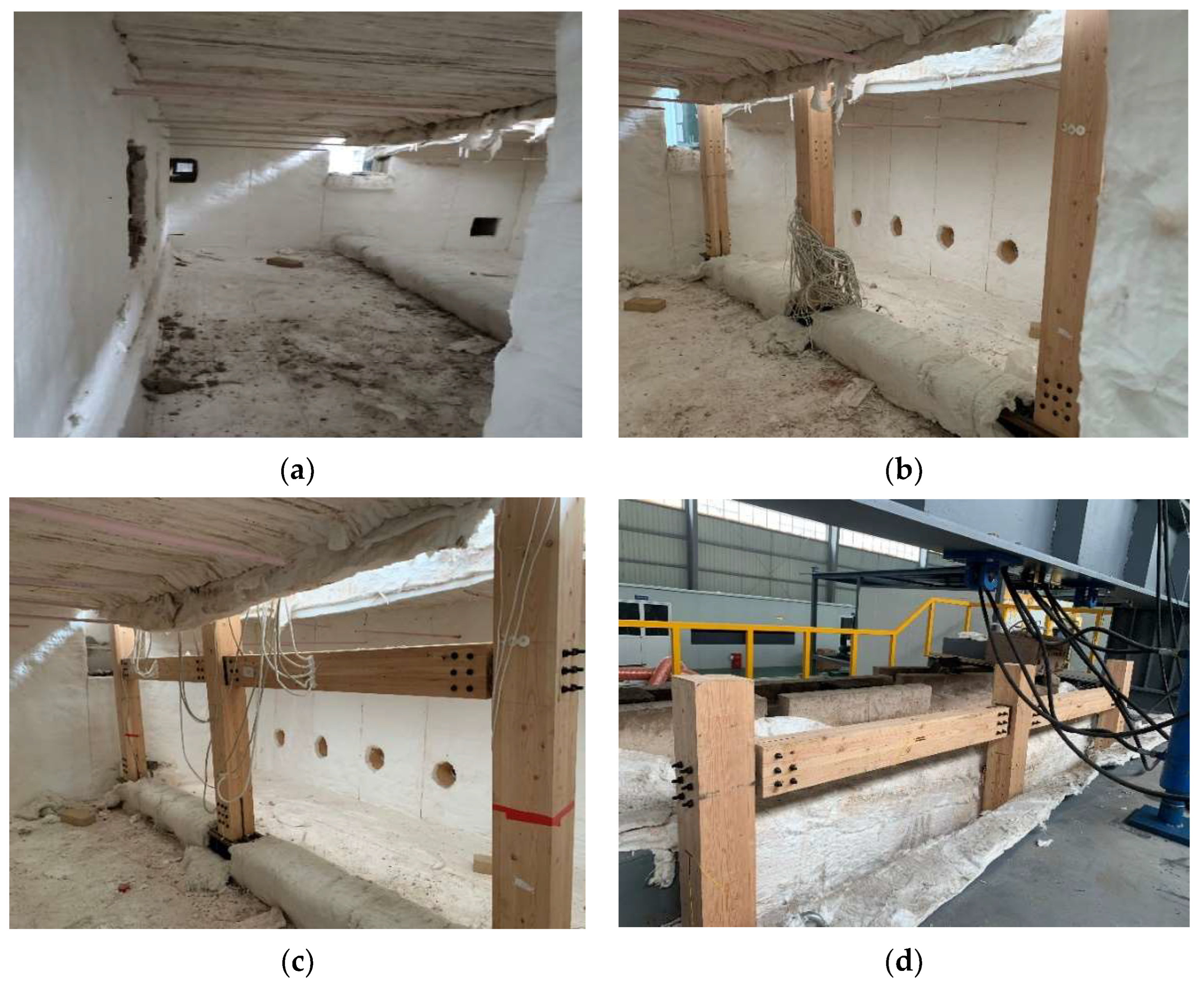
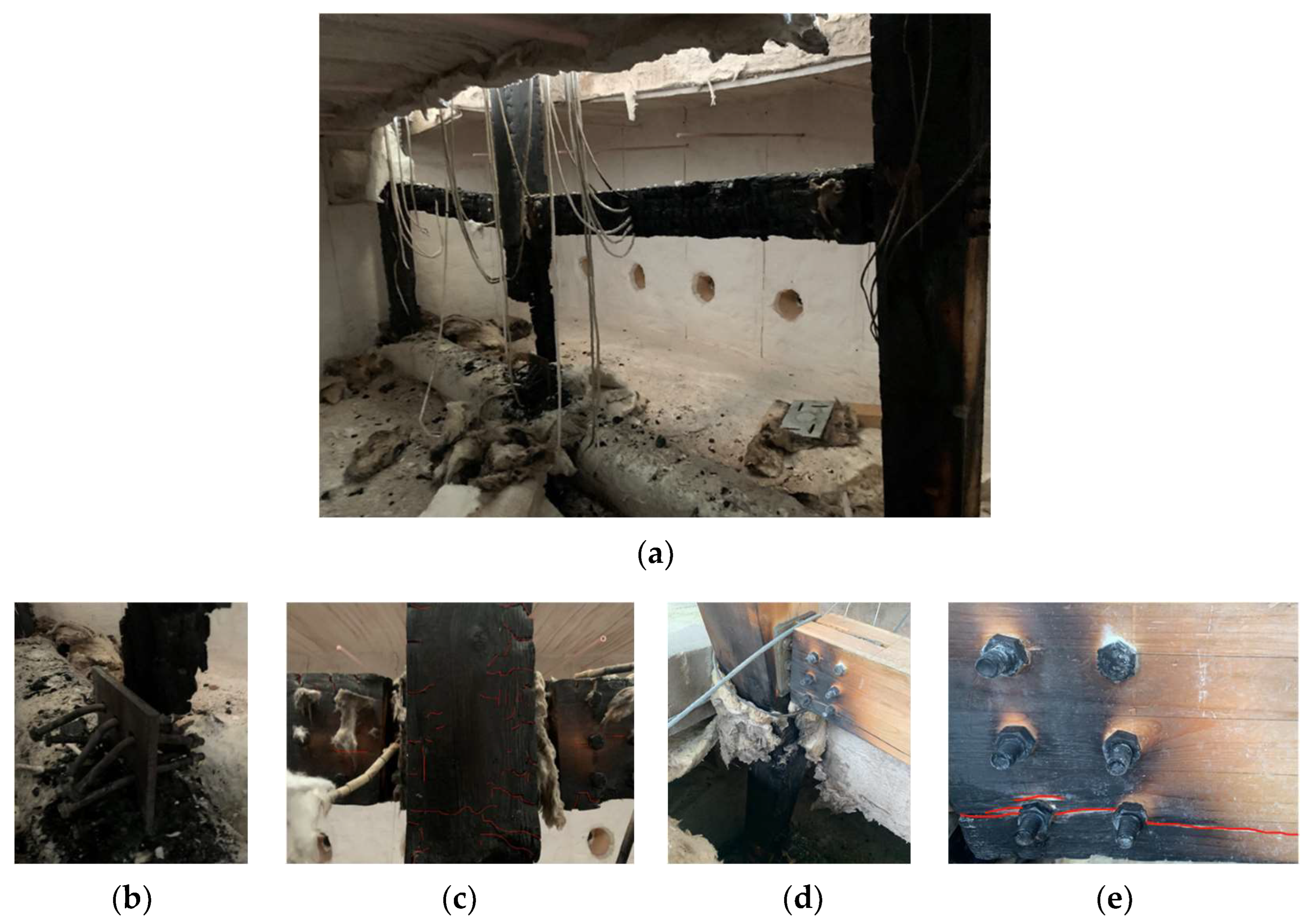
After 44 s of the fire test, white smoke continued to rise from the furnace top. After 1 min 30 s, the fire column first begins to burn, and, then, the exposed part of the glulam timber beams are ignited. At about 8 min, the unprotected part of the frame experienced a flashover. At 17 min 30 s, the vertical displacement of the fire column increased sharply. At 29 min 56 s, the right column frame out-of-plane instability collapsed. The jack could not be loaded stably; then, the test was stopped with the furnace and fire closed. To prevent the structure from continuing to burn, the protective rock wool is removed and the frame is watered to cool. The structural morphology after the test is shown in Figure 8.

3.2. Temperature Distribution

The temperature distribution at different positions of the frame was obtained by thermocouple. 
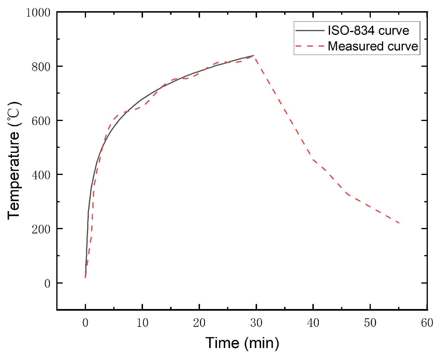
Figure 9 shows the ISO standard heating curve and the measured temperature curve in the fire-test furnace. Compared with the standard heating curve, the actual temperature in the furnace begins to be slightly lower, higher than the standard curve after 3 min, followed by alternating high and low, and, at 12 min, tends to be stable and basically consistent.
The temperature of the fire-exposed column to fire and the temperature field changes at the joints of the beams and columns were measured by embedding thermocouples at different depths in different sections. In order to prevent the borehole arranged by the thermocouple from weakening the cross-section strength, and to measure the temperature changes of different cross-sections and different depths during the heating process, the temperature measuring points of the three-sided fire-exposed side columns are arranged in section 1-1 and 2-2.
Figure 10a shows the temperature curves of different depths (25 mm, 50 mm, and 75 mm) from the fire surface on the bottom middle column sections 1-1 and 2-2. The results show that the temperature of the four fire-exposed wood columns decreases with the increase in depth. The 25 mm depth from the fire surface temperature rise rate increased after 20 min because the depth of the char layer is close to 20 mm, close to this measuring point. Due to the cross section 2-2 being closer to the fire-exposed beam on three sides, the temperature at the same depth is slightly higher than that at cross-section 1-1. When exposed to fire for 30 min, the temperature at the depth of each measuring point in the column section did not reach 300 °C because the charring layer had a certain heat-insulation effect on the wood and prevented the rapid transfer of heat.
Figure 10b is the measuring point temperature curve at different depths of the wood beam exposed to a three-sided fire cross section. It can be seen that the overall temperature decreases with the increase of measuring point depth. The temperature of the measuring point at 25 mm from the fire surface rises the fastest because this measuring point is most affected by the heat at the beam bottom. The temperature of the measuring points above 75 mm depth is basically the same because the top of the beam section is less affected by the temperature of the beam bottom and more affected by the temperature of the fire surface on both sides of the beam. The temperature of the beam section at 25 mm depth after 30 min of fire is much higher than that of the column section at the same depth, indicating that the carbonization rate of the glulam timber beam after the fire is slightly larger than that of the column.
Figure 10c shows the measuring point curves at different depths of the side columns protected by rock wool. It can be seen that, in addition to the measuring point 25 mm away from the fire surface, the temperature of other measuring points remained at about room temperature. The temperature of the measuring point at the 25 mm depth still rises under fire protection, but the temperature is always lower than 100 °C during the fire, indicating that the rock wool outsourcing fire protection is effective.
Figure 10d is the temperature curve of the fire column-base joint and the protected beam–column joint. The diagram shows that the temperature of nuts at the unprotected column base rises rapidly, and the heat is mainly transferred from the steel filling plate and screw exposed to the air on both sides to the inside. The temperature of the beam–column joint connector can still reach more than 200 °C under the protection of rock wool. This is because the fire column and the fire beam transfer heat to the interior at the same time. The heating rate of the nuts with the exposed column base is the fastest, and the second is the column-base steel plate, which indicates that the wood has a certain fire-insulation effect on the inserted steel plate.
It can be seen from the four Figures that the maximum temperature of the cross section shows an upward trend from deep to shallow, regardless of whether the wood member is exposed to the fire. The temperature at the depth of 25 mm from the surface of the same section in the wood member is much higher than that at the depth of 50 mm and 75 mm. It can be seen from the analysis that the temperature of the steel plate and bolt at the beam–column connection is much higher than that of the wood member. Moreover, the temperature of the joint between wood and steel rises rapidly in the fire, resulting in serious weakening of the mechanical properties of the section. The fire protection of steel connectors in timber structures is very important. The necessary fire protection of beam–column joints and column-base joints of a glulam timber structure can improve the fire-resistance limit of the components, so as to improve the collapse resistance of the structure.

3.3. Deformation and Displacement

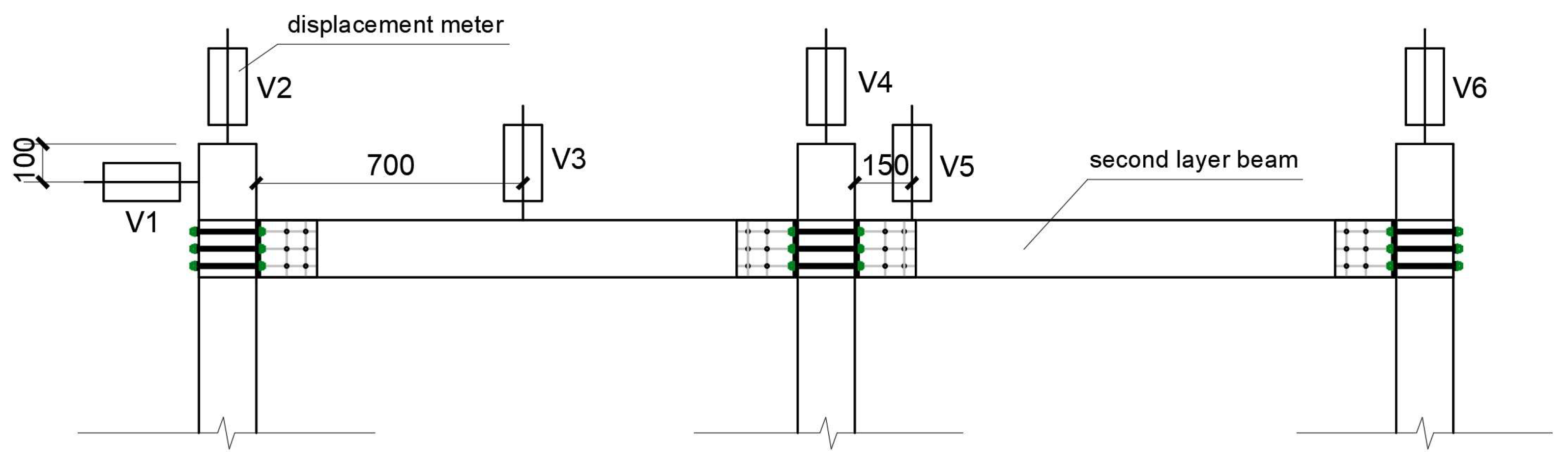
Displacements of columns and beams were monitored by displacement meters during the test. Since the fire-test furnace cover needs to be closed to ensure safety, the displacement of the first layer frame in the furnace cannot be monitored, so this test mainly studies the displacement–time relationship of the second layer frame. The axial compression rate of the fire column is shown in 
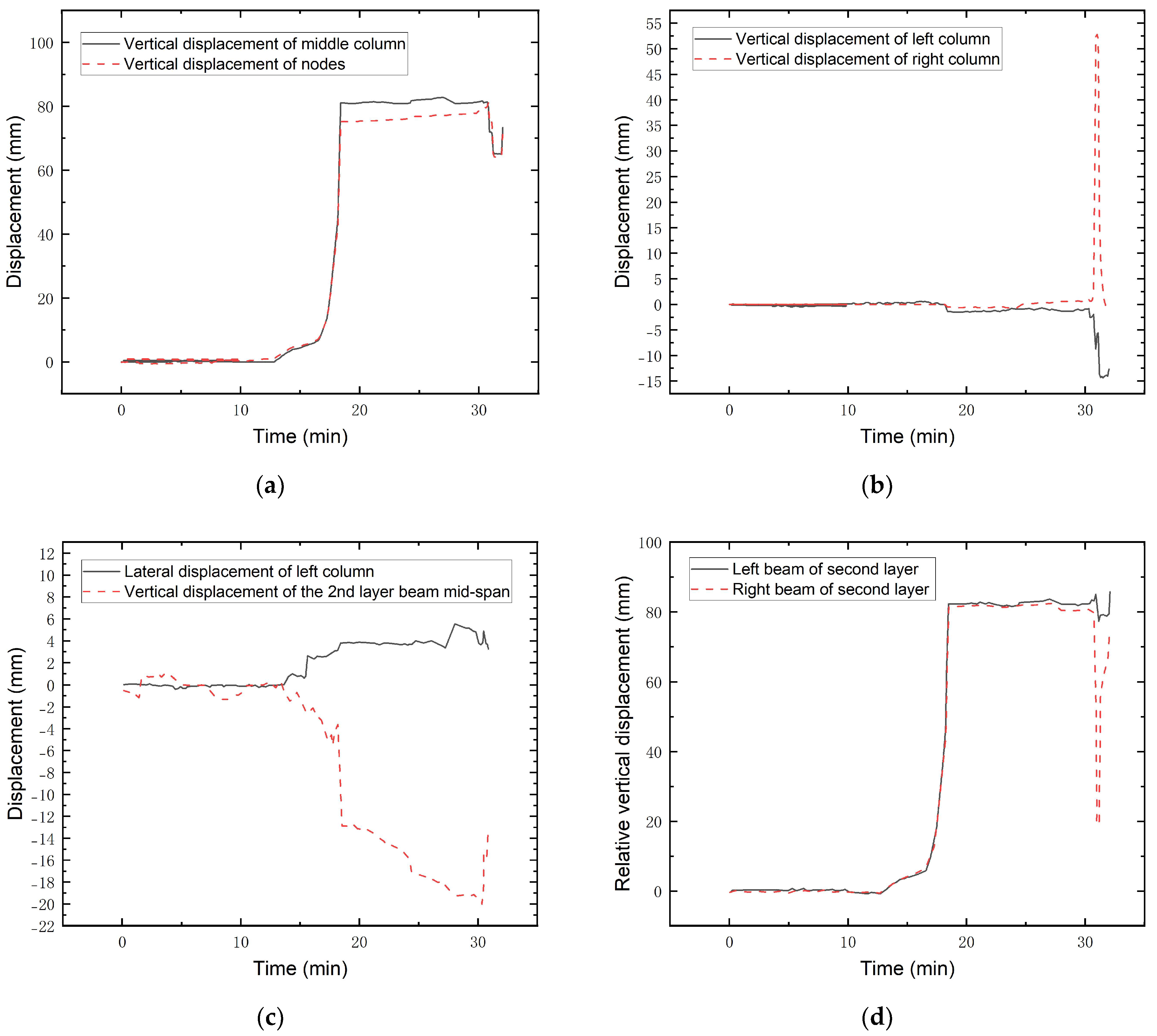
Figure 11.The vertical displacement is positive downward, and the lateral displacement is positive to the right. The displacement–time curves of the column top and the two-story joints in the fire are shown in Figure 12a. It can be obtained that the vertical displacement of the structure remains basically unchanged at the beginning of the fire test. At 16.8 min, the displacement of the fire column is greater than the limit of 22 mm, and the axial compression rate is greater than the limit of 6.6 mm/min. At this time, it can be determined that the fire column has failed. Then, the axial compression deformation rate of the fire column increases rapidly, reaching the highest point of vertical displacement of about 80 mm, which is much larger than the deformation value of the vertical load-bearing member reaching the fire-resistance limit. After the fire failure of the bottom middle column, the vertical displacement of the structure remained stable at 80 mm, indicating that the bottom middle column lost load-carrying capacity at this time. And the pressure at the top of the second column was borne by the timber beams on both sides connected to it. The pressure on the top of the second floor column is borne by the timber beams on both sides connected to it. The glulam frame structure produces a suspension effect and enters the catenary stage.
Figure 12b shows the vertical displacement curves of two side columns. It can be obtained that the vertical displacement of the two side columns is basically maintained at zero during the fire test, indicating that the fire-protection measures of the side columns remain effective during the test. At about 30 min, the vertical displacement of the right column increased instantaneously to 52.8 mm. At this time, the out-of-plane collapse of the right column of the structure occurred, the jack could not continue to stabilize the load, and then, the displacement of the column end returned to the origin. While the right column moves downward, the left column deforms upward.
The lateral displacement of the left column and the vertical displacement of the second floor beam are shown in Figure 12c. It can be seen that the lateral displacement of the left column is kept within 10 mm, and the interstory displacement of the structure is kept in a reasonable range. The change point of the second floor beam midspan vertical displacement coincides with the time point of column failure and structural collapse. After entering the catenary mode, the beam ends begin to bear the tension transmitted at the nodes, resulting in a small displacement of the beam during this time until the structure collapses.
Figure 12d shows the relative vertical displacement curves of the second floor beams on the left and right. When the fire time reaches 17.17 min, the relative vertical displacement at both ends of the beam is greater than 42 mm. According to the limit of UFC 4-023-03, “Design of buildings to resist progressive collapse.” [46], the progressive collapse of the structure can be determined. The test condition in this paper is an axisymmetric structure, and the relative vertical displacement curves of the two side beams are basically the same, which is consistent with the actual situation.

3.4. Numerical Simulation

A finite element model of a glulam timber frame was established in ABAQUS software by comparing the finite element simulation and experimental results of a glulam timber frame under a middle column fire. The feasibility of using finite element software to study the local fire collapse of a glulam timber plane frame is verified. Analysis of the half-structure of a frame model along the symmetry axis of the middle column. The distribution of the temperature field in a finite element simulation is mainly related to the thermal performance and temperature change of the materials. The thermal coefficient mainly includes specific heat capacity, density, and thermal conductivity. The adopted thermal properties in this paper were from the relevant provisions in Eurocode EC5 [47]. The thermal conductivity, specific heat capacity, and density of the wood and steel used in this section change with the temperature are according to Eurocode EC5 [47]. The main mechanical properties of the wood used at room temperature were obtained through the wood properties test, including compressive strength, compressive elastic modulus, tensile strength parallel to the grain, shear strength parallel to the grain, and shear modulus. The material parameters that lack the measured data refer to the theoretical values of the strength related to the wood properties of Eurocode EC5 [47]. The constitutive relationship of wood at room temperature is shown in Table 3. Bolts and steel plates are regarded as ideal elastic-plastic materials for constitutive models of steel. The element type is selected as the special element DC3D8 for heat transfer analysis. The analysis model includes beam, column-wood members, and steel-plate bolt connectors. The structural field analysis model is consistent with the thermal analysis model, and the mesh type of structural field analysis is set as a C3D8R element. After modeling, the temperature field and structural field are analyzed by sequential coupling.
The temperature-field distribution and carbonization depth of beam–column members can fully reflect the influence of fire on glulam timber members.
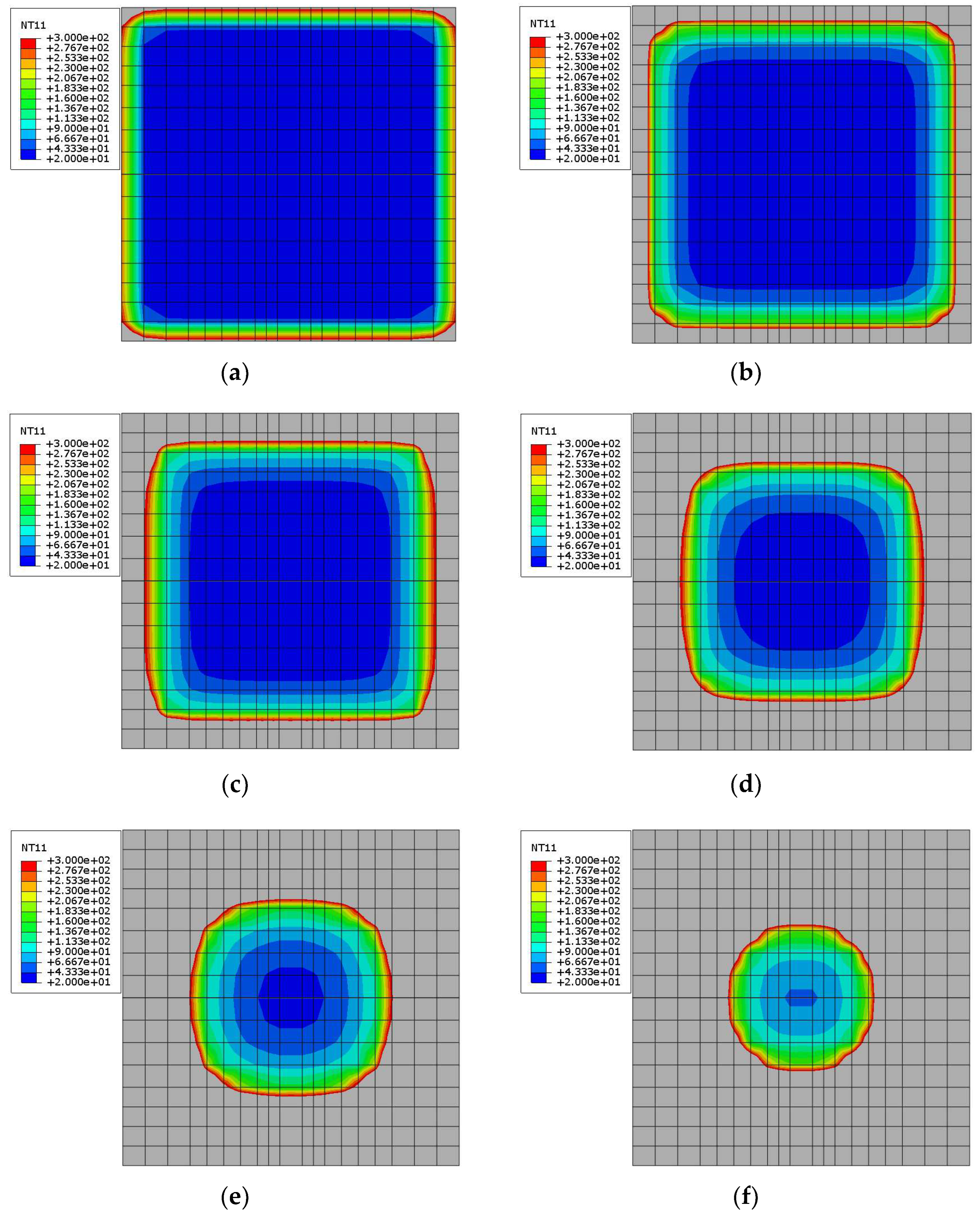
 Figure 13 and Table 4 give the carbonization situation and carbonization speed simulated at different times at the 1/2 section of the fire column. The grey area in the cross section of the fire column is above 300 °C, which can be regarded as the carbonized layer area. It can be obtained that the carbonization begins first at the corner only 2.5 min after the fire, and the column end is gradually circularized, which is caused by the simultaneous thermal convection on both sides of the corner. The carbonization depth increases with the increase of fire time, and the remaining cross section decreases continuously. The rate of carbonization tends to decrease because the carbonized layer first formed at the periphery prevents further transfer of heat to the interior.
The numerical model has the ability to provide additional insight into the fire test because, during fire tests, limited sensors can be utilized.
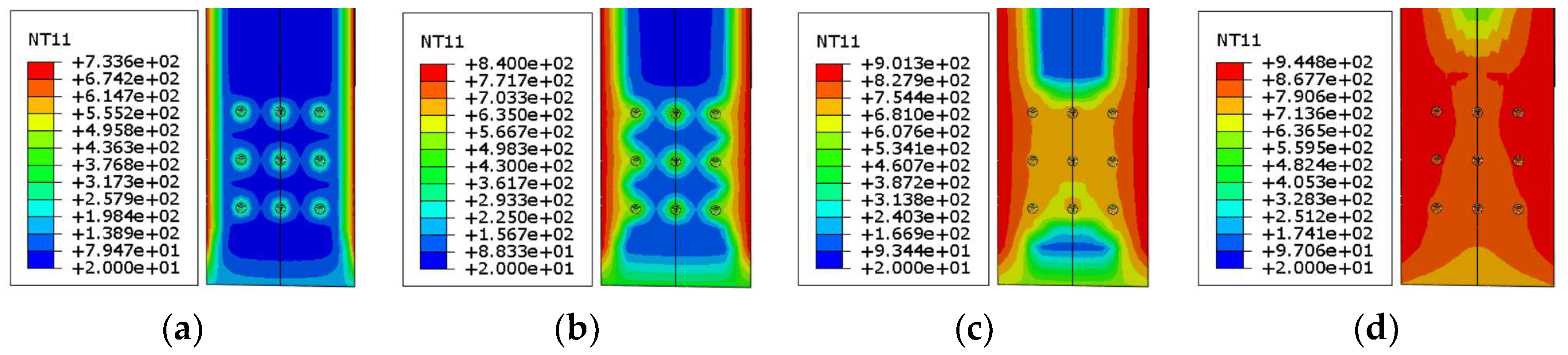
Figure 14 shows the temperature-field distribution of the beam end section at the bottom middle column joint in the fire. Although the beam–column joint is protected by fire protection and not directly exposed to fire, the transfer of the internal temperature field of the component still exists. It can be found that the heat of the beam unexposed to fire at the node is continuously transmitted upward from the bottom of the beam end with the increase of the fire duration. Although it was not directly exposed to fire, the temperature of the beam end rose to more than 300 °C in about 15 min. This is because the thermal conductivity of the steel plate connectors in direct contact with wood is better than that of wood. The carbonization caused by the high temperature at the beam end will lead to a decrease in the bearing capacity of the beam–column joints, which needs attention.
Figure 15 shows the temperature-field distribution at different moments at the beam end of the bottom middle column joint. It can be seen that the heat is transmitted from the wood and the screw holes on both sides of the fire to the inside. This is because the nut exposed to the air absorbs heat faster and transfers heat to the screw, which then passes through the screw to the wood surface around the screw hole. The temperature of the wood around the screw hole can reach about 300 °C when the fire occurs for 15 min. The wood around the screw carbonized in 15 min, resulting in a rapid decrease in the strength of the column at the column-base node.
As one of the main forms of prefabricated buildings, the fire resistance of joints of beam–column glulam timber structures is particularly important.
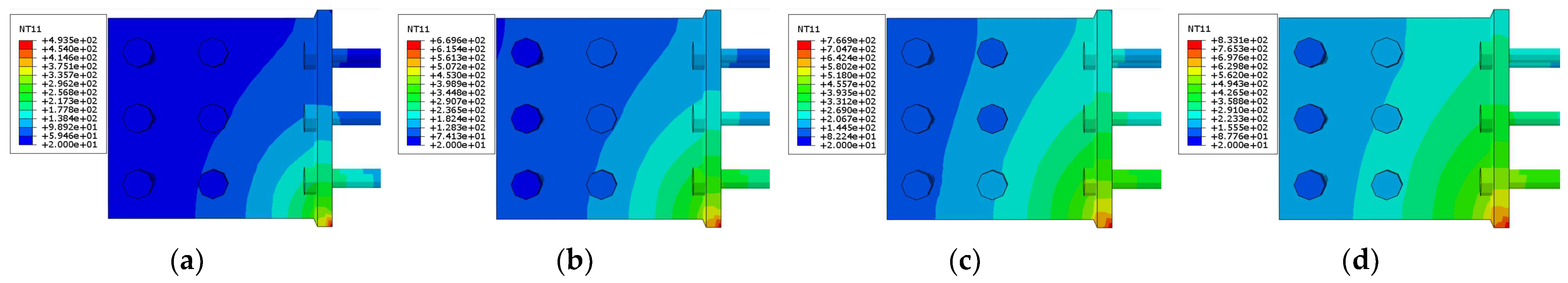
Figure 16 shows the temperature-field distribution of intermediate beam–column joint connectors at different times. It can be seen that the steel has good thermal conductivity. The heat is gradually transferred to the inside of the steel plate through the exposed side of the steel plate. The temperature of the bolts is also transferred from the steel plate and the temperature decreases from the bottom to the top. Even if the fire duration reaches 60 min, the temperature of most areas of the connector is still below 300 °C. This is because the wood on both sides of the steel plate isolates the heat transfer to a certain extent and plays a good heat-insulation role.
Figure 17 shows the temperature-field distribution at different times of the connecting pieces of the pillar foot in the bottom column. It can be seen that the heat of the column-base joint connector is transmitted to the interior through the two sides in contact with the air and the nuts. Relatively speaking, the nut absorbs heat faster. When the fire time reaches 30 min, the temperature of most areas of the column-base connector rises to more than 300 °C. The temperature of the whole connector reaches more than 700 °C when the fire time reaches 60 min. When the temperature exceeds 600 °C, the yield strength and stiffness of the steel will be seriously reduced. At this time, the stability of the column-base connector should be paid attention to.
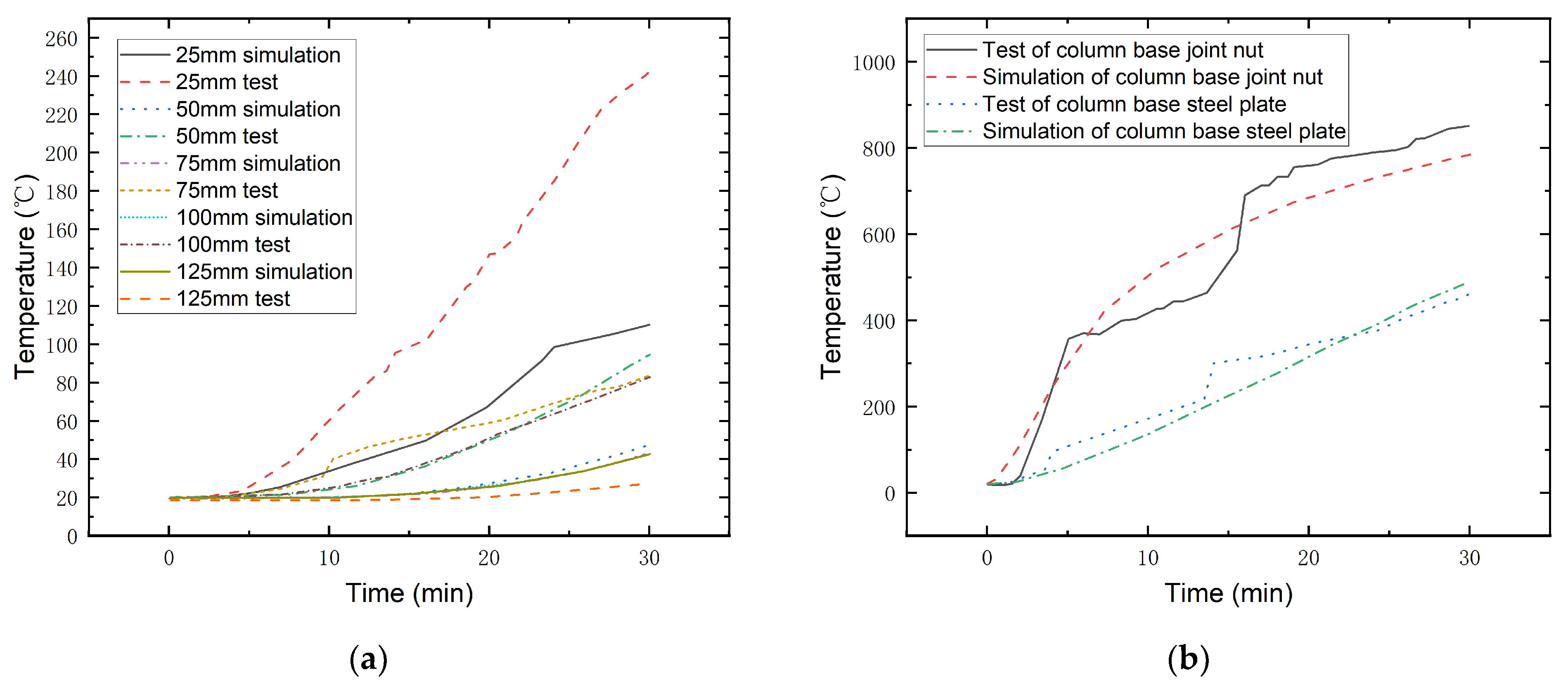
Figure 18 shows the comparison between the experimental values and the finite element simulation values of the temperature changes of the wood measuring points and the connecting points. The measured values of each measuring point are basically consistent with the curve trend of finite element simulation values. The value of the three-sided fire beam is slightly larger than the simulated value. The reason is that the formation and shedding of the wood carbonization layer during the test makes the steel-plate connectors be exposed to the air, which aggravates the heat transfer.
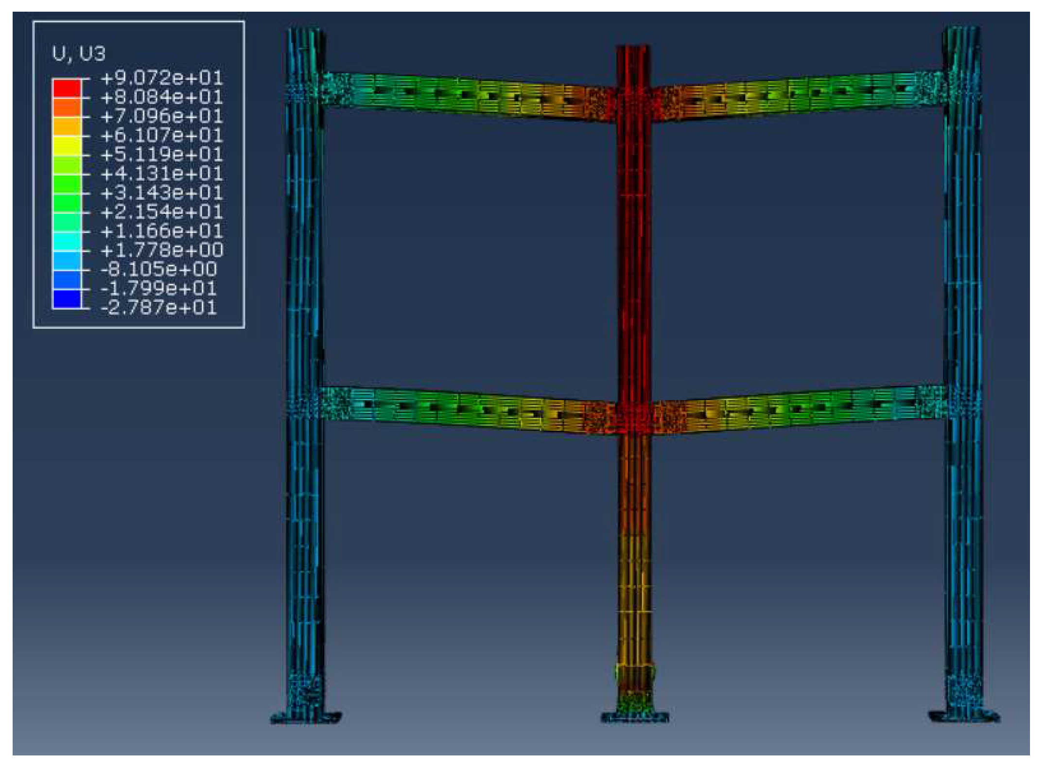
The failure mode of the simulated frame thermal–mechanical sequential coupling results begins with the axial compression failure of the unprotected column-base joints at the bottom middle column. The displacement cloud diagram of the simulation results is shown in Figure 19. The failure of the fire-exposed column and the collapse of the frame are determined by the deformation of the fire-exposed column to fire exceeding the limit value. It can be obtained that the maximum displacement of the fire column reaches 90.72 mm. The displacements of the two columns remain basically unchanged, and the beams at both ends fall with the middle column at the joints. The displacement deformation is consistent with the test results.
Figure 20 shows the comparison between the experimental value and the simulated value of the vertical displacement of the column top in the fire. The fire-resistance limit test value of the fire column has a large deviation from the simulated value, but the two curves show the same development law in the early stage of the fire. There are three main reasons why the test value is greater than the simulation value. First, the material parameters of the finite element model are more idealized, ignoring the natural defects of wood. There may have been a local failure of the glue line where the central timber column was loaded at the top, as it was loaded in parallel with the glue line and the wood grain. Because the glue line is not modeled, its characteristics cannot be checked in the simulation. Second, the finite element simulation adopts the temperature-structure sequential coupling method for analysis, without considering the holding load influence of the fire component on the fire-resistance limit. Third, this model does not carry out secondary development to define the damage to the wood. Its failure displacement lags behind the actual situation and cannot simulate the brittle failure of the fire column, but its displacement development law still has reference significance for the actual situation.
The axial force of the column that cannot be measured in the test under fire is analyzed by numerical simulation. Figure 21 is the axial force curve of the fire-exposed column and beam. After 19 min of fire, the axial force of the middle column began to decrease, and the column began to fail. At 28.5 min, the axial force decreased rapidly and dropped to a low point. At this time, the fire column completely failed and withdrew from work. In the early stage of the fire, the fire column sinks slowly, and the beam end gradually bears the tension. The tension reaches the maximum and remains stable at 16 min. After 26.5 min, the tension gradually decreased to zero point, and the axial force at the beam end changed from tension to pressure. These changes show that in the process of fire column failure, the joint beam ends begin to produce tension to form catenary action. With the continuous increase of the fire time, the catenary action finally fails. The tension at the beam end decreases rapidly and withdraws from the work, causing the progressive collapse of the structure.
The fire experiment is the most real and effective, but due to safety considerations and other factors, many data are often difficult to collect during the test. The finite element simulation can help us understand the whole process of structural response and internal force analysis of specimens in the fire process, which can provide some reference for fire research.
The experimental research and numerical simulation research methods in this paper can be applied to the design and test stages of some practical projects, but there are still many shortcomings, that need to be studied in the future: (1) in this paper, only the performance of a glulam timber plane frame structure in a local fire is studied, and the influence of more surrounding structural constraints on the collapse performance of glulam timber frame under fire can be considered; (2) the influence of the cooling stage on the mechanical properties of the timber structure is not considered. The heat transfer inside the wood member during the cooling stage may cause the continuous carbonization of the wood member to weaken the cross section and cause the collapse of the structure; (3) due to the limitation of test conditions and safety considerations, the influence of the line load on the beam on the collapse performance of the structure in the fire is not considered in this paper. Much data on the underlying components exposed to fire have not been collected. Such tests in the future can further optimize the loading and measurement schemes; and (4) the temperature–structure sequential coupling method is adopted when the finite element simulation is used to study the structural thermal–mechanical coupling analysis. The influence of component loading and failure on the temperature field is not considered, so how to carry out a more refined thermal–mechanical coupling direct analysis needs to be further improved.

4. Conclusions

In this paper, through the analysis of the research status of progressive collapse resistance of a frame structure under fire, Douglas fir was selected as the material for making a glulam timber frame. Through the analysis of the mechanical properties of the material, a scale structure of a two-story two-span glulam timber plane frame was made. The structural response of a glulam timber frame middle column under fire is studied by experimental and finite element simulation. The following conclusions can be drawn.
  • The failure time of the middle column in fire is 16.8 min, and the time to determine the progressive collapse of the structure is 17.17 min when the rotation angle exceeds the limit. The progressive collapse of the glulam timber frame structure may occur in a very short time after the failure of the middle column;
  • Different from the instantaneous collapse of the structure under the action of an earthquake, secondary damage will occur to the structure with the spread of fire under local fire, which will lead to progressive collapse. Therefore, the setting of fire compartments and partitions to prevent the spread of fire is of great significance to the improvement of the fire-protection function of buildings;
  • The temperature field of the glulam timber frame after fire shows that the fire protection of the steel connectors of the timber structure is very important. The connections between steel and wood are heated rapidly under fire, and the weakening of section strength is more serious. The necessary fire protection of beam–column joints and column-base joints of glulam timber structure can improve the fire-resistance limit of members, so as to improve the collapse resistance of structure under fire;
  • The heat will be transmitted to the interior through the two sides of the column-base connector exposed to the fire and the nuts. The temperature of the column-base joint connector without fire protection is increased. The nuts absorb heat faster, causing the temperature of the wood around it to rise. Due to the thermal insulation effect of the wood carbonized layer, the temperature of the steel plate inserted in the wood remained relatively low in the fire;
  • The glulam timber frame structure can remain stable for a long time after the middle column fails in fire and the structural deformation exceeds the limit. The change of axial force on the fire column and beam end shows that in the failure process of the fire column, the joint beam end begins to produce tension to form catenary action, which can prevent the rapid collapse of the structure. With the increase of fire time, catenary action finally fails. The tension at the beam end rapidly decreased and then withdrew from work, eventually leading to the progressive collapse of the structure;
  • The catenary effect of the beam is the main reason for the long-term stability after the fire of the middle column and the structural deformation exceeds the limit. According to the analysis of the failure mechanism of the frame, the following suggestions are put forward in the design of the progressive collapse resistance of the middle column of the glulam timber frame structure exposed to fire: (1) improve the compressive strength of the side column to improve its lateral stiffness in the whole frame; (2) the slenderness ratio of the bolts in the steel filling plate connected with the middle column should be reduced to enhance the bearing capacity of the joint so that the middle column can better play the role of catenary effect in the process of fire damage on three sides; and (3) increase the bending ultimate bearing capacity of the beam near the column exposed to fire;
  • There are still some shortcomings to be explained in this paper. Since the specimen is scaled down to fit into the furnace by design, the heat released by the combustion of wood in the furnace is not considered. The member size of the specimen is different from that of the actual building. In practical engineering, wood has a certain influence on the heat release rate in the compartment. The ISO 834 [46] curve was used in the test and it is different from the actual fire process. The test data were only used as a reference for real building fire conditions. Therefore, it will be more practical to study the progressive collapse of the frame under natural fire.

Author Contributions

Conceptualization, J.H. and L.W.; methodology, J.H. and L.W.; software, J.H.; validation, J.H. and L.W.; formal analysis, J.H.; investigation, J.H.; resources, J.H. and L.W.; data curation, L.W.; writing—original draft preparation, J.H.; writing—review and editing, L.W.; visualization, J.H.; supervision, L.W.; project administration, J.H. and L.W.; funding acquisition, L.W. All authors have read and agreed to the published version of the manuscript.

Funding

This research was funded by the Jiangsu Province Science Fund for Distinguished Young Scholars (Grant No. BK20211536) and General Program of National Natural Science Foundation of China (Grant No. 52378518).

Institutional Review Board Statement

Not applicable.

Informed Consent Statement

Not applicable.

Data Availability Statement

The data sets generated during the current study are available from the corresponding author upon reasonable request.

Acknowledgments

The authors express many thanks to Nanjing Gongda Construction Technology Co., Ltd.

Conflicts of Interest

The authors declare no conflict of interest.

References

  1. Zhao, M.; Shang, H.; Yang, Y.; Gao, W. Research on applicability and development prospects of modern wood residential structure in rural China. In Proceedings of the 10th International Symposium on Project Management, Beijing, China, 18 June 2022. [Google Scholar]
  2. Xu, P.; Guan, C.; Zhang, H.; Li, G.; Zhao, D.; Ross, R.J.; Shen, Y. Application of nondestructive testing technologies in preserving historic trees and ancient timber structures in China. Forests 2021, 12, 318. [Google Scholar]
  3. Drozdzol, K. Thermal and mechanical studies of perlite concrete casing for chimneys in residential buildings. Materials 2021, 14, 2011. [Google Scholar] [PubMed]
  4. Lakshmanan, R. Benefits of glulam timber roof structure for airport passenger terminal building. J. Inst. Eng. Ser. A 2022, 103, 689–694. [Google Scholar]
  5. Barber, D.; Gerard, R. Summary of the fire protection foundation report—Fire safety challenges of tall wood buildings. Fire Sci. Rev. 2015, 4, 5. [Google Scholar]
  6. Tung, S.; Su, H.; Tzeng, C.; Lai, C. Experimental and numerical investigation of aroom fire in a wooden-frame historical building. Int. J. Archit. Heritage 2020, 14, 106–118. [Google Scholar]
  7. Chen, S.; Zhang, L.; Zhang, Y.; Wang, Y. Initial failure and collapse mechanism of steel frame structures under localized fire. J. Build. Struct. 2015, 36, 115–122. [Google Scholar]
  8. Wang, X.; Zhang, S. A review of charring rate of wood and various influencing factors. Struct. Eng. 2018, 34, 177–182. [Google Scholar]
  9. White, R.; Nordheim, E. Charring rate of wood for ASTM E 119 exposure. Fire Technol. 1992, 28, 5–30. [Google Scholar]
  10. Friquin, K. Material properties and external factors influencing the charring rate of solid wood and glue-laminated timber. Fire Mater. 2011, 35, 303–327. [Google Scholar]
  11. Zhang, Y.; Wang, L. Research on flashover prediction method of large-space timber structures in a fire. Materials 2021, 14, 5515. [Google Scholar]
  12. Zhang, Y.; Wang, L.; Chen, L. Energy-based time equivalent approach for evaluating the fire resistance of timber components exposed to realistic design fire curves. Struct. Design. Tall Spec. Build. 2021, 30, e1861. [Google Scholar] [CrossRef]
  13. Zhang, Y.; Wang, L. Energy-based time equivalent method for evaluating the fire resistance of timber-concrete composite structures exposed to travelling fires. Struct. Infrastruct E, 2022; ahead of print. [Google Scholar] [CrossRef]
  14. Zhang, Y.; Zhang, X.; Wang, L. Experimental validation and simplified design of an energy-based time equivalent method applied to evaluate the fire resistance of the glulam exposed to parametric fire. Eng. Struct. 2022, 272, 115051. [Google Scholar] [CrossRef]
  15. Zhang, Y.; Zhi, W.; Zhang, X.; Ni, W.; Xu, C.; Xu, Y.; Wang, L. Experimental and numerical study on the validity of the energy-based time equivalent method for evaluating the fire resistance of timber components exposed to travelling fires. J. Build. Eng. 2023, 76, 107169. [Google Scholar] [CrossRef]
  16. EN 1995-1-2; Part 1-2: General-Structural Fire Design. Eurocode 5-Design of Timber Structures. GB-BSI: London, UK, 2004.
  17. König, J. Effective thermal actions and thermal properties of timber members in natural fires. Fire Mater. 2006, 30, 51–63. [Google Scholar] [CrossRef]
  18. Bartlett, A.; Hadden, R.; Bisby, L. A Review of factors affecting the burning behaviour of wood for application to tall timber construction. Fire Technol. 2019, 55, 1–49. [Google Scholar] [CrossRef]
  19. Xu, Q.; Chen, L.; Harries, K.; Zhang, F.; Liu, Q.; Feng, J. Combustion and charring properties of five common constructional wood species from cone calorimeter tests. Constr. Build. Mater. 2015, 96, 416–427. [Google Scholar] [CrossRef]
  20. Kinjo, H.; Katakura, Y.; Hirashima, T.; Yusa, S.; Saito, K. Deflection behavior and load-bearing period of structural glued laminated timber beams in fire including cooling phase. J. Struct. Fire Eng. 2018, 9, 287–299. [Google Scholar]
  21. Fonseca, E.M.M.; Gomes, C. FEM analysis of 3D timber connections subjected to fire: The effect of using different densities of wood combined with steel. Fire 2023, 6, 193. [Google Scholar] [CrossRef]
  22. Wiesner, F.; Bisby, L. The structural capacity of laminated timber compression elements in fire: A meta-analysis. Fire Saf. J. 2019, 107, 114–125. [Google Scholar] [CrossRef]
  23. Hu, X.; Chen, L.; Xu, Q.; Han, C.; Len, Y. Experimental study of the mechanical behavior of glulam beams exposed to three-side fire. J. Build. Struct. 2020, 50, 87–93. [Google Scholar]
  24. Zhang, J.; Xu, Q.; Li, W.; Li, X.; Shang, J. Experimental study on the charring rate and residual flexural capacity of timber beams after exposure to four-side fire. China Civ. Eng. J. 2013, 6, 24–33. [Google Scholar]
  25. Xu, Q.; Li, X.; Zhang, J.; Mu, B.; Xu, Q.; Li, S. Experimental study of the mechanical behavior of timber beams exposed to three-side fire. China Civ. Eng. J. 2011, 44, 64–70. [Google Scholar]
  26. Xu, Q.; Li, X.; Mu, B.; Zhang, J.; Xu, M.; Li, S. Static experimental research on mechanical behavior of timber beams with lime putty finishing after fire. J. Build. Struct. 2011, 32, 73–79. [Google Scholar]
  27. Li, X.; Li, S.; Xu, Q.; Xu, Q.; Zhang, J.; Mu, B. Experimental research on fire endurance of timber columns exposed to four-side fire. Build. Struct. 2010, 40, 115–117. [Google Scholar]
  28. Xu, Q.; Li, X.; Zhang, J.; Mu, B.; Xu, M.; Li, S. Experimental study on the mechanical behavior of timber columns after exposure to fire on four sides. China Civ. Eng. J. 2010, 45, 79–85. [Google Scholar]
  29. Chen, L.; Xu, Q.; Hu, X. Experimental research on fire endurance of moderately long glulam columns exposed to four-side fire. J. Build. Struct. 2020, 41, 95–103. [Google Scholar]
  30. Zhang, J.; Xu, Q.; Bai, Y.; Cai, J. Fire resistance of bolted steel-glulam-steel connections. J. South China Univ. Technol. 2015, 43, 58–65. [Google Scholar]
  31. Zhang, J.; Cai, J.; Liu, Z.; Zhang, Y.; Zhang, M. Experiment for fire endurance of bolted timber connection nodes with slotted-in T-shaped steel plate. J. Shenyang Univ. Technol. 2015, 37, 594–600. [Google Scholar]
  32. Zhang, Y.; Zhang, J.; Li, W.; Cai, J. Experimental research and FEA on fire resistance performance of bolted glued laminated timber frame with slotted-in steel plates. J. Build. Struct. 2018, 39, 53–65. [Google Scholar]
  33. Mpidi Bita, H.; Currie, N.; Tannert, T. Assessment of disproportionate collapse for multi-storey cross-laminated timber buildings. In Proceedings of the World Conference on Timber Engineering, Vienna, Austria, 22–25 August 2016. [Google Scholar]
  34. Mpidi Bita, H.; Currie, N.; Tannert, T. Reliability analysis and disproportionate collapse for multi-storey cross-laminated timber buildings. In Proceedings of the World Conference on Earthquake Engineering, Santiago, Chile, 9–13 January 2017. [Google Scholar]
  35. Mpidi Bita, H.; Tannert, T. Numerical optimisation of novel connection for cross-laminated timber buildings. Eng. Struct. 2018, 175, 273–283. [Google Scholar] [CrossRef]
  36. Mpidi Bita, H.; Tannert, T. Disproportionate collapse prevention analysis for a mid-rise flat-plate cross-laminated timber building. Eng. Struct. 2019, 178, 460–471. [Google Scholar] [CrossRef]
  37. Mpidi Bita, H.; Tannert, T. Experimental study of disproportionate collapse prevention mechanisms for mass-timber floor systems. J. Struct. Eng. 2020, 146, 4019199. [Google Scholar] [CrossRef]
  38. Petrycki, A.; Salem, O. Structural integrity of bolted glulam frame connections reinforced with self-tapping screws in a column removal scenario. J. Struct. Eng. 2020, 146, 4020213. [Google Scholar] [CrossRef]
  39. Eva, F. Analysis of structural failures in timber structures: Typical causes for failure and failure modes. Eng. Struct. 2011, 33, 2978–2982. [Google Scholar]
  40. Bedon, C.; Fragiacomo, M. Fire resistance of thermally insulated log-house timber walls. Fire Technol. 2019, 55, 307–341. [Google Scholar] [CrossRef]
  41. Jessop, D.; Abu, A.; Wade, C.; Spearpoint, M.; Gerlich, H. Performance of a light timber-framed compartment in natural fire subjected to lateral load. Fire Mater. 2019, 43, 175–188. [Google Scholar] [CrossRef]
  42. Matthew, W.; Andrew, M. Timber/steel composite members in multi-storey buildings under fire test loadings. J. Struct. Integr. Maint. 2017, 2, 152–167. [Google Scholar]
  43. GB/T 50329; Standard for Test Methods of Timber Structures. China Building Industry Press: Beijing, China, 2012.
  44. GB/T 50708; Technical Code of Glued Laminated Timber Structures. China Building Industry Press: Beijing, China, 2012.
  45. EN 1995-1-2: 2004 Eurocode 5; Design of Timber Structures–Part 1-2: General–Structural Fire Design. European Committee for Standardization (CEN): Brussels, Belgium, 2004.
  46. UFC 4-023-03; Design of Buildings to Resist Progressive Collapse. Department of Defense: Washington, DC, USA, 2009.
  47. Eurocode 5; Design of Timber Structures—General—Structural Fire Design. British Standards Institution (BSI): London, UK, 2004.
Figure 1. The detailed construction of the frame. (a) Schematic diagram of test-frame size; (b) Glulam timber-beam size; (c) Glulam timber-column size; (d) Middle column joint; (e) Side column joint; (f) Detailed dimension of joints.
Fire 06 00374 g001aFire 06 00374 g001b
Figure 2. Details of steel foundation beams. (a) Elevation view; (b) Plan view.
Fire 06 00374 g002
Figure 3. Frame assembly process. (a) Assembly of foundation beam; (b) Assembly of columns; (c) Assembly of bottom beam; (d) Assembly of the second floor beam.
Fire 06 00374 g003
Figure 4. Loading and protection of the test frame. (a) Fire-protection method in furnace; (b) Furnace top loading method.
Fire 06 00374 g004
Figure 5. Fire test loading diagram.
Fire 06 00374 g005
Figure 6. Position of temperature measurement points. (a) Measurement points of the frame (b) Measurement points of fire-exposed column section 1-1; (c) Measurement points of fire-exposed column section 2-2; (d) Measurement points of three-sided fire beam section 3-3; (e) Measuring points of protected side column section.
Fire 06 00374 g006
Figure 7. Layout of displacements measuring points.
Fire 06 00374 g007
Figure 8. The structural morphology after the test. (a) Overall deformation of the frame; (b) Joint of column base; (c) Beam and column cracks near middle column joint; (d) The buckling damage of the second layer right column; (e) Cracks in the second layer right beam–column joints.
Fire 06 00374 g008
Figure 9. Measured furnace temperature curve.
Fire 06 00374 g009
Figure 10. Temperature–time curves of the frame. (a) Temperature distribution of fire column section; (b) Temperature distribution of three-side fire beam; (c) Temperature distribution of fire-protection side column; (d) Temperature distribution of node connectors.
Fire 06 00374 g010
Figure 11. Axial deformation ratetime curve of fire column.
Fire 06 00374 g011
Figure 12. Displacementtemperature curves of the frame. (a) Vertical displacement of fire column; (b) Vertical displacement of side column; (c) Lateral displacement of left column and midspan vertical displacement of second layer left beam; (d) Relative vertical displacement at both ends of second layer beam.
Fire 06 00374 g012
Figure 13. Carbonization of the section at the height of 1/2 layer of the bottom column exposed to fire at different times. (a) 2.5 min; (b) 10 min; (c) 15 min; (d) 30 min; (e) 45 min; and (f) 60 min.
Fire 06 00374 g013
Figure 14. Temperature-field distribution at different moments at the beam end of the bottom middle column joint. (a) 15 min; (b) 30 min; (c) 45 min; and (d) 60 min.
Fire 06 00374 g014
Figure 15. Temperature-field distribution at different moments of wood sections at the foot joints of the bottom middle column. (a) 15 min; (b) 30 min; (c) 45 min; and (d) 60 min.
Fire 06 00374 g015
Figure 16. Temperature-field distribution of intermediate beam–column joint connectors at different times. (a) 15 min; (b) 30 min; (c) 45 min; and (d) 60 min.
Fire 06 00374 g016
Figure 17. Temperature-field distribution at different times of connecting pieces of pillar foot in the bottom column. (a) 15 min; (b) 30 min; (c) 45 min; and (d) 60 min.
Fire 06 00374 g017
Figure 18. Comparison between the experimental value and the simulated value of temperature. (a) Measurement points of the beam; (b) Measurement points of the connectors.
Fire 06 00374 g018
Figure 19. The simulation deformation of the frame.
Fire 06 00374 g019
Figure 20. Comparison between experimental values and simulated values of the fire-exposed column vertical displacement.
Fire 06 00374 g020
Figure 21. The axial force of the fire-exposed column and beam end. (a) The axial force of the fire-exposed column; (b) The axial force of the beam end.
Fire 06 00374 g021
Table 1. Compression modulus table of Douglas fir at different temperatures.
Temperature (°C)Compression Modulus along Grain
(MPa)
Radial Compression Modulus
(MPa)
Tangential Compressive Modulus
(MPa)
2013,008.961503.52822.83
10012,827.551389.81542.82
18011,515.341048.76522.60
25011,077.76745.23223.21
Table 2. Processing table of specimens.
Material Used: Douglas Fir
TypeComponent Size: Length (L) × Width (B) × Height (H)
(mm)
Laminate Thickness
(mm)
Number
11400 × 100 × 15030 × 54
2150 × 150 × 327530 × 53
Table 3. Mechanical performance parameters.
Elastic
Modulus
(MPa)
Shear Modulus
(MPa)
Poisson’s RatioFracture Energy
(J·m−2)
Tensile Strength
(MPa)
Compressive Strength
(MPa)
Shear Strength (MPa)
EL *13,009GLR976νLR0.372DL30,782FL,t96.15FL,c54.54VLR5.01
ER1503GRT234νRT0.435DR363FR,t18.18FR,c5.59VRT4.76
ET823GLT781νLT0.467DT363FT,t18.18FT,c9.42VLT5.01
* L represents the longitudinal direction of the grain, R represents the radial direction of the transverse grain, and T represents the chord direction of the transverse grain. LR represents the plane determined by the longitudinal direction of the grain and the radial direction of the transverse grain. RT represents the plane determined by the radial and tangential directions of the transverse grain, and LT represents the plane determined by the radial and tangential directions of the transverse grain.
Table 4. Average carbonization speed of fire column section at different times.
Fire Time (min)153045
Average carbonization speed (mm/min)0.810.740.71
Disclaimer/Publisher’s Note: The statements, opinions and data contained in all publications are solely those of the individual author(s) and contributor(s) and not of MDPI and/or the editor(s). MDPI and/or the editor(s) disclaim responsibility for any injury to people or property resulting from any ideas, methods, instructions or products referred to in the content.

