1. Introduction
Saunas have been used to provide relax and health benefits for a long time, with sweat houses being operated by ancient civilizations even 3000 years ago [
1]. Over the last 50 years, they have become a typical amenity in the hospitality (e.g., hotels) and fitness (e.g., gyms, spas) industries; their market is expected to experience a steady growth at a CAGR (compound annual growth rate) of about 7%, at least until 2026 [
1]. However, the involved structural components and equipment make the likelihood of fire incidents in saunas relatively high, and the learning of sauna fires through media or technical publications is currently not uncommon [
2,
3]. The source of ignition consists of the presence of electrical heaters or incandescent stones; a substantial amount of combustibles is also often included within sauna scenarios, which mostly comprise timber (e.g., benches and walls), fabric (e.g., towels and linen), and chemicals (e.g., detergents). A fire may start quite easily as a result of short circuits or direct contact between hot materials and combustibles, frequently caused by human errors. The potentially high ambient temperature—even exceeding 90 °C—tends to contribute to its spread over the whole compartment. Passive fire-protection systems are often employed, since their effectiveness in avoiding or limiting fatalities appears established; nevertheless, fire events may cause remarkable loss or damage of property, together with lengthy business interruption, if not properly contained and possibly suppressed by an action of some kind.
So, the inclusion of active fire-protection systems in the design of saunas has become ever increasing, which is also promoted by specific requirements imposed through laws and standards. Quite an expected outcome, the challenge for designers and engineers has turned into an attractive opportunity within the fire-protection system market, as almost every fitness center and most resorts or recreational facilities are currently endowed with saunas. In this frame, performance-based design applied to the various elements of the built environment in terms of fire protection seems to foster the use of innovative technologies able to control the fire both thermally and spatially until emergency responders arrive on the scene. Yet, saunas are also designed to reduce the costs associated with the amount and storage of the selected fire-extinguishing agent [
4]. Among them, the popularity of water mist is increasing for a variety of stationary applications [
5]: its control and suppression capability is the subject of a substantial body of the literature that comprises scenarios relating to high-hazard storages [
6], car parks [
7], timber buildings [
8], and pipelines containing natural gas [
9,
10,
11]. Mitigation of explosions was investigated as an additional action by water mist in highly hazardous storage facilities [
12]. Its success can be mainly attributed to a discharge of generally less water than that by sprinkler systems, since fragmentation into tinier droplets yields a faster evaporative action [
13,
14]. Dedicated studies were also focused on water-mist action in suppressing compartment fires, mainly emphasizing the need for controlled discharge [
15] and systems that govern activation on a detection-based feedback [
16].
Unfortunately, the research specifically focused on sauna fires is still relatively limited and mostly consists of case studies, even though it is seminal [
2,
3]: for instance, Howe and Lloyd showed that sprinklers are mainly installed in saunas located within a sprinkler-protected site, whereas water mist is often chosen if no sprinkler system is already present or can be integrated [
2]. So, this work was primarily inspired by the available experimental research on water-mist fire suppression. It includes several studies where the discharge is released against canonical fire scenarios, both solid—(e.g., wood cribs, lithium-ion batteries) [
17,
18] and liquid-fueled (e.g., pool fires) [
19,
20], together with works on real-scale—actually large-scale and highly hazardous—scenarios [
6,
7,
9,
10,
11]. These latter works present compartments where the characteristic length—usually the room height in compartment-fire problems [
21]—is of the same order of magnitude as that of saunas. Since a spray discharge is involved, the acquired knowledge of water-mist spray characterization in terms of both atomization and dispersion [
22,
23,
24], and the achievements about spray/flame interaction [
25], also served as a foundation for the present work. As an additional source of guidance to design a test rig, several standards are currently available for water-mist systems [
26,
27], which provided technical guidelines in devising the experimental setup assembled for the present work. On the other hand, no standardized protocol to evaluate water-mist performance for sauna fire scenarios is currently available; so, this work is also aimed at proposing an approach that may become a standard reference to the purpose, being that it is inspired by the Annex B of standard NFPA 750 [
27]. Overall, the latter was followed, as it reports a strategy to challenge water-mist systems against generic fire scenarios and assess their performance.
An experimental setup was developed and built as fully representative of a sauna environment from both the structural (i.e., involved materials, dimensions, and arrangement of the included components) and the thermo-hygrometric (i.e., temperature and vents) standpoint. In consistency with the aim of reproducing the actual action by water mist within that scenario, the discharge system was also designed and scaled accordingly. Several physical quantities were measured or evaluated; various parameters were considered and varied throughout the test series: location of the ignition source, presence of drywall boards, bench-to-wall and nozzle-to-wall distance, ventilation, and initial room temperature. An evaluation of fire spread and intensity under the tested configurations was quantitatively performed by introducing a damage ratio that ultimately allowed assessing the impact of the varied parameters. The present work may serve as a reference for future assessments of control and suppression capability in a scenario that is currently not covered by standardized procedures. Moreover, the parametric study may also provide guidance to fire-protection system designers, especially if water-mist technology is selected for this application.
2. Materials and Methods
The main objective of the conducted experiments consisted of assessing quantitatively the ability of a water-mist system to successfully control and possibly suppress a sauna fire, with extinction being considered unexpected by this technology [
5,
13], yet welcome. So, the main sources of ignition were identified as the first step, then a test scenario was developed and realized to reproduce the most relevant configurations in terms of geometry and involved combustibles. A testing procedure was also devised as founded on the recommendations provided by recognized standards [
26] and aimed at combining the following tasks:
evaluation of fire hazards within the tested environment;
evaluation of the compartment conditions;
expression of performance objectives in terms of thermal/spatial control of the fire and suppression;
emphasizing the worst-case scenario through an a posteriori analysis of the outcomes from the test series.
It is worth noting that this kind of real-scale experiment is relatively expensive, especially in terms of material consumption and waste production; therefore, a limited number of tests—lower than ten—was carried out. Nevertheless, some statistical analysis was performed to assess repeatability, mostly referred to the initial free-burn condition (i.e., unhindered evolution of the fire).
2.1. Scenario and Geometry
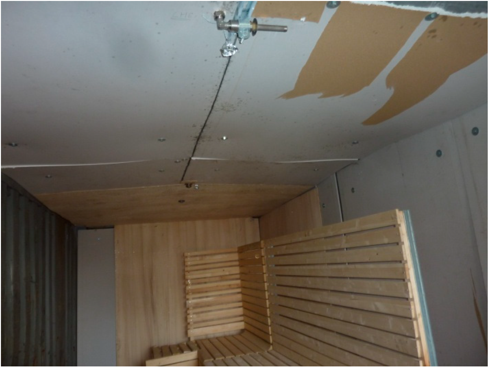
The test chamber is presented in the technical sketches of
Figure 1, with some photos also being shown in
Figure 2 and
Figure 3. The dimensions involved in
Figure 1 are reported in
Table 1, together with the chamber height. The employed benches and internal walls were made up of timber beams; drywall boards were attached to the back vertical surface of the benches. Plywood boards were used to upholster the ceiling and walls. The facility was assembled and placed within a corrugated-iron container, the door of which—kept closed in all the conducted experiments, except for those featuring natural ventilation—was of 0.7 × 1.9 m size. The developed setup was designed to include the structural components and the items of typical saunas, as described in studies dedicated to fire protection of those compartments [
2,
3].
Since the electrical heater was considered one of the main sources of fire hazard in terms of probability and potential extent of the fire among those reviewed in
Section 1, an ignition source was devised to resemble it and reproduce the fire arisen from electrical heaters typical of actual saunas. To the purpose of also complying with available standards, a wood crib was selected as the ignition source [
17,
28], following the recommendations by Annex G of a recognized standard for water-mist tests [
29]. The basic foundation of this design choice consists of a solid-fueled fire being more spatially spread than a liquid-fueled one, thus making the former more similar to an electric-heater fire. So, a 4-layer crib (overall size of 300 × 300 × 150 mm) was employed; each stick featured a square base of 38 mm side (thickness), and its length was 300 mm. The peak heat release rate of wood-crib fires is yielded by a well established formulation [
28]:
where
HRR is heat release rate,
MLR is mass-loss rate, Δ
hc is wood heat of combustion (=12 MJ kg
−1 [
28]),
C is a constant (=7.44 × 10
−4 [
28]),
S is the clear spacing between sticks in the same layer (=50 mm),
H is the crib height,
mi is the initial crib mass (=2.9 kg on average, for the cribs used in this experiment), and
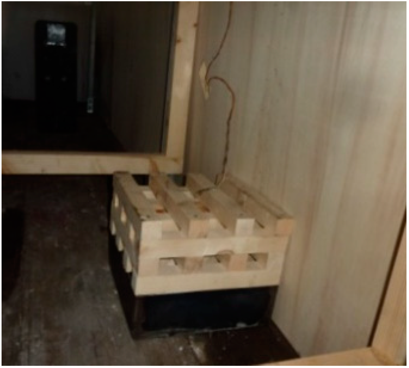
t is the stick thickness. The average heat release rate resulted from calculation as 230 kW. The crib was placed onto a metal container, hosting 0.47 L of water—employed to balance the potential unevenness of the base—and 0.24 L of heptane.
The latter served as the accelerant and was manually ignited to start the fire;
Figure 4 shows a photo of the whole crib/container assembly. As shown in the sketch of
Figure 1, the test chamber included two configurations (C1 and C2), embodying two fire scenarios, each of which presents different locations of the ignition source (i.e., the wood crib). Notably, the wood-crib assembly was located behind the benches and on the floor in both configurations, with it being placed at the corner in configuration C1, while being placed at the center of the wider drywall board in configuration C2.
Those scenarios were aimed at reproducing typical locations of the electric heater within saunas, thus allowing one to assess the impact of the position of the ignition source on fire spread. Testing a sauna fire within a container may imply boundary and initial conditions different from those of an actual fire occurring in a real sauna. The thermo-hygrometric operating conditions of most saunas consist of 80 ± 5 °C ambient temperature and 10 ± 2% relative humidity [
30], as opposed to steam baths that feature lower temperature and higher humidity. Initial room temperature and heat transfer may bear the main discrepancy with respect to real scenarios. As an assessment of the potential impact of this parameter on fire development, initial room temperature was governed in one of the performed tests and raised above 80 °C by an industrial heater. However, when not imposed, its variations and variations of the global heat-transfer coefficient were assumed negligible with respect to temperature rise due to a fire event [
31]: in fact, even significant changes in the heat-transfer coefficient between a compartment and its outer environment, under natural convection, may affect room temperature by less than 10 °C, whereas typical flame temperature is in the order of 1000 °C. Moreover, no major impact by variations of relative humidity was also expected; relative humidity within the test chamber was not recorded, but tests were carried in summer mornings, which made relative humidity within the container arguably low. On the other hand, the use of a hydrocarbon (i.e., heptane) as the accelerant for the wood-crib fire yields water (steam) as a product of combustion reaction, but the fuel concentration was sufficiently low (i.e., about 8 mL heptane per 1 m
3 ambient air) to neglect the related raise of humidity. As a conservative measure, timber benches were left to dry out before installation, thus making them more prone to involvement with the fire, were flames to ever reach them. Notably, their moisture content may be assumed as lower than 5%, following a similar approach to the drying of timber components [
17].
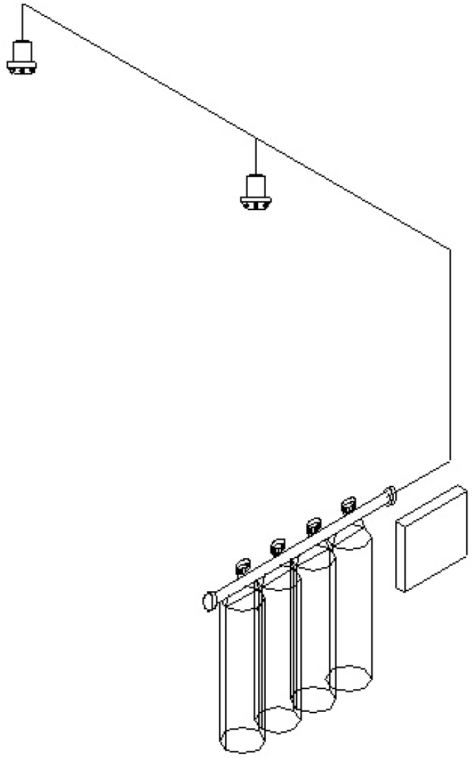
The discharge system consisted of a high-pressure delivery unit, stainless steel piping, water-mist nozzles, and the detection set; a sketch including all the items is presented in
Figure 5. Notably, the delivery unit included four cylinders, each of which is of 80 L capacity: three of them hosted water, whereas the other one contained nitrogen to pressurize the system. The nitrogen’s initial pressure was 150 bar, which allowed the initial water pressure at the nozzle to be greater than 100 bar. As the core of the discharge system, two water-mist nozzles manufactured by Bettati Antincendio S.r.l. (code NWMO14) were inserted in the enclosure at the ceiling height (i.e., 2.4 m, as reported in
Table 1).
The devised arrangement within the chamber—presented in
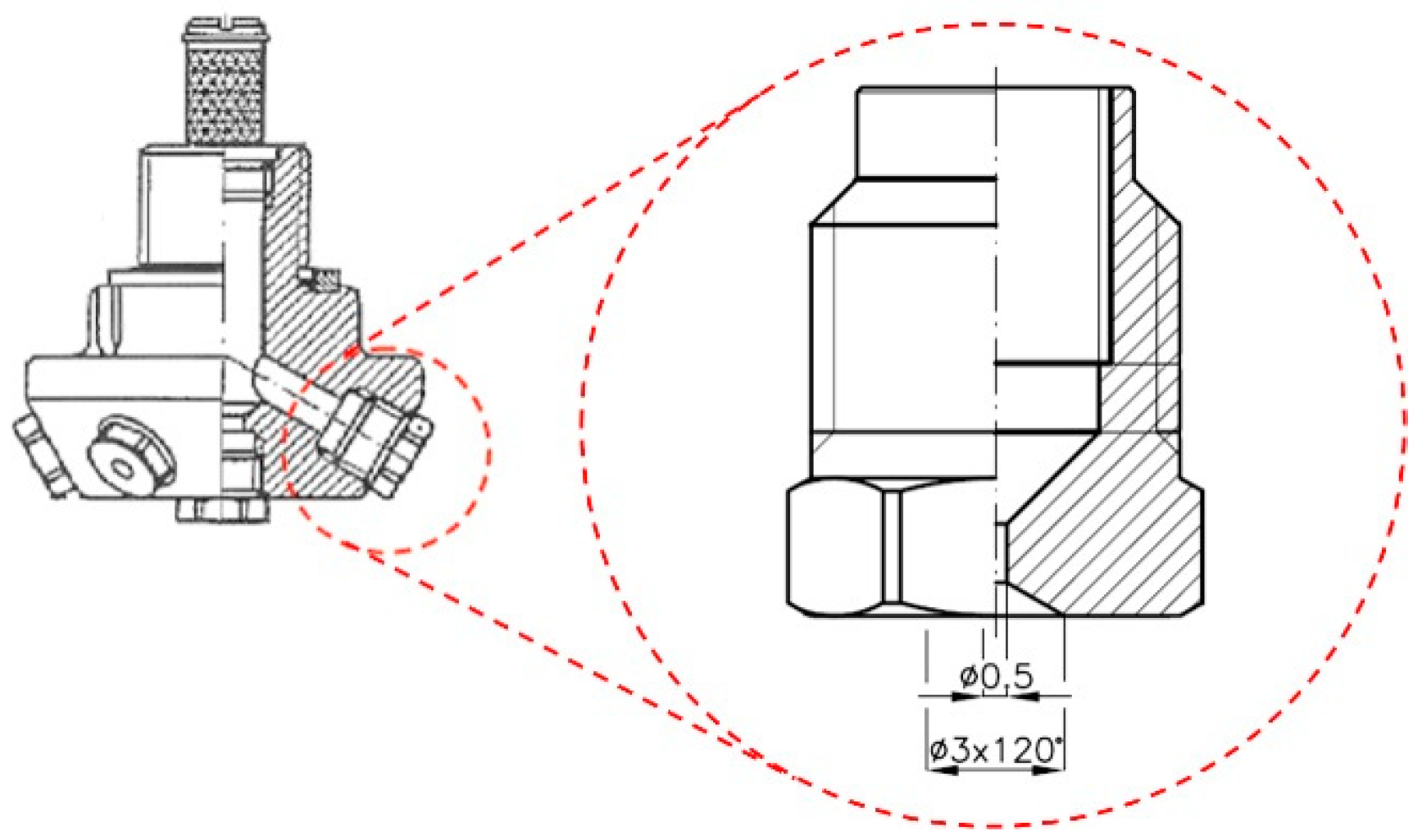
Figure 1—made the area coverage of each nozzle 3.6 × 3.6 m. This type of nozzle features seven pressure-swirl injectors (one central and six peripheral, as shown in the technical sketch of
Figure 6) and overall K-factor of 1.4 L min
−1 bar
−0.5. Therefore, a 10 min minimum duration of the discharge could be achieved within the enclosure under the reported operating conditions. The released spray was characterized in previous works [
23,
24]; the characteristic droplet size (Sauter Mean Diameter) at 1 m distance from the nozzle outlet could be estimated, as in the order of 50 μm.
The detection set consisted of a heat detector (by Kidde-Fenwal Inc., threshold temperature of 165 °C, in accordance with recent regulations for residential and shipboard applications [
32]), installed at the ceiling height within the test chamber, as shown in
Figure 1. In actual saunas, the discharge is also activated upon temperature feedback, and two detectors would be typically employed, each one at
d_riv distance from the closer nozzle. However, only one detector was inserted in the developed experimental setup to anticipate the worst-case scenario, both for configuration C1 (
Figure 1a) and for configuration C2 (
Figure 1b). Overall, it is worth noting that the designed discharge system was merely inspired by the Annex B of a generic standard on water mist [
26], since no guidance is available for this specific application.
2.2. Instruments and Experimental Procedure
As a typical measurement in fire experiments, temperature was recorded at various locations and within specific devices by seven thermocouples (type K, wire diameter of 0.5 mm, 1 Hz acquisition frequency, and accuracy complying with standard IEC 584-2). Notably, the following list identifies the probes and reports their respective positions in the test chamber, as well as their scope in terms of measured parameter:
T_gas—three probes used to record gas temperature 76 mm below the ceiling at the vertical symmetry axis of the ignition source (wood crib); gas temperature 76 mm below the ceiling at the heat-detector location (i.e.,
Riv in
Figure 1); gas temperature 76 mm below the ceiling at the virtual heat-detector location (not inserted, as noted in
Section 2.1), symmetric to
Riv with respect to the symmetry axis in the sketches of
Figure 1, respectively;
T_crib—probe used to record gas temperature at the center of the wood-crib top surface;
T_sts—probe used to record surface temperature of the timber bench bottom surface, at the vertical symmetry axis of the ignition source;
T_clg—probe used to record surface temperature at the ceiling and at the symmetry axis of the ignition source;
T_rad—probe associated with hot-plate thermometer and located at 500 mm height from the floor.
All the three
T_gas thermocouples were conveniently shielded to limit and virtually prevent wetting by water droplets throughout the discharge. The hot-plate thermometer was developed as a device to quantitatively evaluate heat flux in configurations where radiation prevails over other heat-transfer modes (e.g., furnaces) [
33]; its applicability to fire scenarios was also successfully validated [
34], and hot-plate thermometry has been employed in a variety of full-scale tests, since radiation is largely predominant as flames are involved [
7]. This instrument features a steel plate exposed to radiation and an insulating slab on its back side, with a thermocouple (
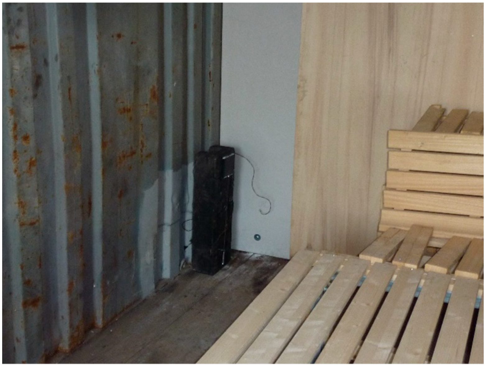
T_rad, in this experiment) welded onto it. The hot-plate thermometer was placed in front of the presumed fire location, between the wood crib and the involved bench, at 500 mm height from the floor; a photo of its location in tests carried out against configuration C1 is presented in
Figure 7.
Pressure measurements were taken within the nitrogen tank and at the nozzle outlet. Moreover, a load cell was employed to measure wood-crib (±0.5 g accuracy) and bench mass (±0.5 kg accuracy) before and after tests to estimate the burning ratio. In consistency with the procedure adopted prior to starting each experiment (
Section 2.1), the materials were left out to dry out after each test before weighing in order to rule out the effect of water absorbed during the discharge.
A procedure was developed to organize the experiments through a test matrix based upon varying the selected governing parameters towards an identified worst-case scenario. In a similar manner to the design of the discharge system (
Section 2.1), this approach was founded on the guidelines from Annex B of a well established standard on water mist, which recommends developing a path that leads to the worst case, also setting some pass/fail criteria for the tested system [
26]. A limited number of parameters was varied throughout the experiments so as to emphasize the most significant factor among the other numerous factors in a real scenario. Notably, the following set was identified:
Location of the ignition source—varied between configuration C1 and C2, as reported in
Section 2.1 and
Figure 1;
Initial room temperature (
Ti)—almost equal to outside ambient temperature in most tests (20–30 °C), above 80 °C in two of them (operating an industrial heater, as mentioned in
Section 2.1);
Discharge activation time (τact)—governed by the heat-detector threshold or equal to a fixed, pre-assigned value (180 s);
Ventilation—closed or open door (natural ventilation);
Distance between the nozzles and the wall behind benches (
D)—1.15 m (=
L2/2) or 1.8 m (=
d2/2), as shown in
Figure 1 and reported in
Table 1;
Presence of drywall boards attached to the back of the benches;
Distance between benches and the wall behind (δ)—benches against the wall (δ = 0), or δ = 0.250 m.
The discharge was manually activated 5 s after the heat-detector alarm turned on, which was deemed a conservative offset to estimate the delay in actual systems; however, delayed manual discharge was also performed to challenge the system against a longer free burn.
As previously reported, nozzle-to-wall distance was generally kept constant; however, tests with a larger distance were also conducted, which also implied droplets potentially bouncing or evaporating against the opposite wall (i.e., the one closer to the nozzle). Drywall boards were attached to the back of the benches in the tests, where a gap between benches and wall (
δ) was applied.
Table 2 shows the test matrix with all variables included. This approach leads one to identify a worst-case scenario (i.e., Test no. 7 in
Table 2), as recommended by the followed guidance [
26].
2.3. Approach to Data Analysis
The analysis of both the most immediate outcomes of each test and of the quantitative dataset was carried out through an approach including a set of actions and the implementation of relationships and formulations. Notably, the developed methodology consisted of:
Opening the test chamber at the end of each test and checking if any flames, smoldering fires, or charring materials were still present after the discharge, thus allowing, first, observations about thermal control and extinction, as defined by a recognized standard [
27];
Distinguishing successful from unsuccessful suppression primarily by the presence of a sharp decay in temperature trend at the locations where gas or surface temperature was measured, which also allows emphasizing instances of fire regrowth; as an additional approach, the same observation was applied to the heat-flux trend;
Identifying the time at which temperature readings by thermocouple
T_crib fall below wood-ignition temperature (~220 °C [
35]) that is the physical threshold to determine suppression on timber surfaces [
17], thus marking the absence of flames at the ignition source (i.e., the most hindered location and a surely deep-seated fire); it is acknowledged that the open literature actually presents a set of values for the various categories and types of timber, so the selected value may be considered as conventionally representative;
Carrying out a close comparative examination of the photos taken before and after each test to qualitatively estimate the amount of materials involved with fire (i.e., based on the extent of the visibly burnt surface), as suggested to assess damage ratio of timber parts [
2,
3];
Evaluating, quantitatively, wood-crib and bench damage ratio as (
mi–
mf)/
mi, where
m is mass, while indexes
i and
f refer to initial (pre-test) and final (post-test) load-cell reading, respectively [
7,
17,
36];
Calculating incident radiant heat flux
q relating to the hot-plate thermometer through the relationship proposed in the literature [
34]:
where
εPT is emissivity of the plate thermometer (=0.95,
de facto a blackbody surface),
σ is the Stefan-Boltzmann constant (=5.67 × 10
−8 W m
−2 °C
−4),
TPT is temperature of the plate thermometer recorded by thermocouple
T_rad,
hPT is convective heat-transfer coefficient (=10 W m
−2 °C
−1 [
34]),
Kcond is conduction correction factor (=22 W m
−2 °C
−1 [
34]),
T∞ is room temperature (i.e., thermocouple reading prior to starting the fire),
ρst is steel density (=8100 kg m
−3),
cst is steel specific heat capacity (=400 J kg
−1 °C
−1),
s is thickness of the steel plate included in the assembly (=0.7 mm), and
t is time.
It is worth noting that a quantitative expression of successful (or unsuccessful) suppression would rigorously stem from an evaluation of the heat release rate (HRR) trend throughout free burn and discharge, in accordance with the definition provided by available standards [
27]. However, this measurement is often hardly feasible in a real-scale scenario, since calorimetric methods usually apply to configurations with smaller length scale. So, temperature and heat-flux measurements were employed, as they allow inferring HRR trends, even though HRR—an integral quantity—cannot be explicitly extrapolated out of local quantities, such as the readings from thermocouples and hot-plate thermometer.
3. Results
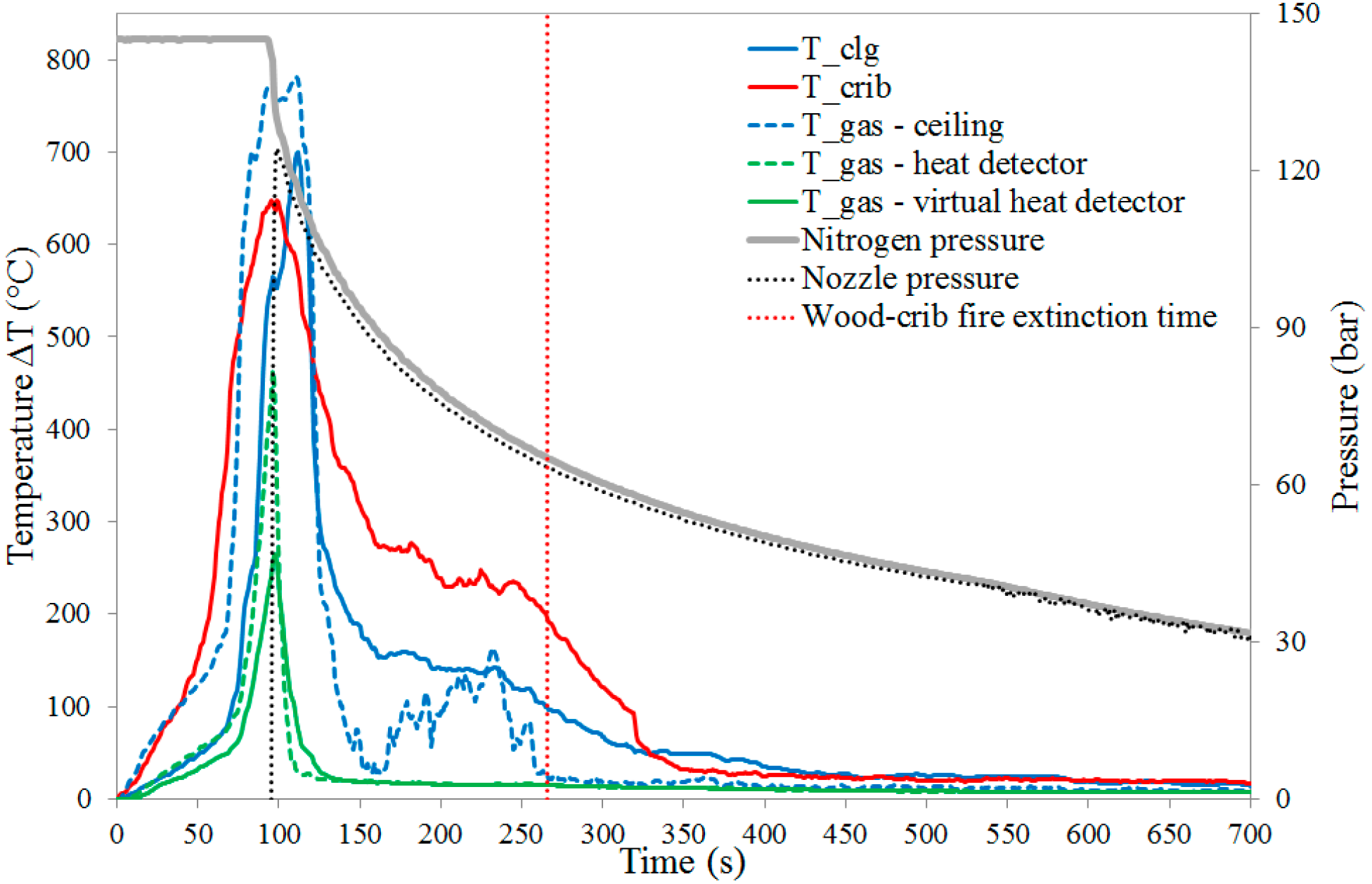
As an example, the dataset of gas-temperature and ceiling-surface temperature readings, together with pressure signature, is shown in
Figure 8, where the profiles are presented for Test no. 1 as a function of time. Notably, temperature
T is actually reported as temperature difference Δ
T =
T −
Tamb, where
Tamb is ambient temperature (i.e., thermocouple reading prior to starting the fire). This strategy is aimed at offsetting discrepancies—even though relatively small—in ambient temperature between tests conducted on different days; it was also applied to Tests no. 6 and 7, where initial room temperature was imposed as greater than 80 °C (
Table 2). The origin of the time coordinate is set at the start of the fire (i.e., manual ignition of the heptane pool fire below the wood crib); the actual discharge initiated as pressure (i.e., relative pressure) at the nozzle suddenly rose up from 0 to nitrogen pressure, which implied that pressurized water reached the nozzle exit. As noted in
Section 2.3, the time at which gas temperature at the center of the crib fell below wood-ignition temperature is also marked in the plot as the conventional achievement of wood-crib fire extinction. It is worth noting that gas temperature at the ceiling raised more rapidly than surface temperature, but it also decreased down to smaller values as the discharge was activated. That can be explained by the higher thermal inertia of solid materials, even when involved with fire, together with the ability of water mist to perform convective flame cooling as soon as the two flows interact [
17]. The fluctuations exhibited by gas temperature at the ceiling, even when thermal control was reached (in the 150–250 s timespan), suggest that high-pressure water mist emphasizes mixing of hot and cooler gas streams as a result of turbulence, a finding also reported in previous works [
6,
7].
Gas temperature at the wood crib showed the slower decay under a milder slope with respect to the other temperature profiles, which supports the use of that reading as a mark to assess the effective action of the discharge (
Section 2.3).
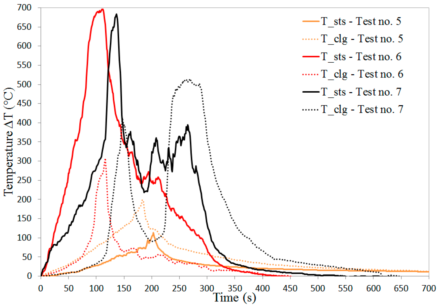
As the most relevant parameters to quantify thermal stress and degradation imposed to the involved materials, surface-temperature trends are shown both at the bottom of the timber benches and at the ceiling for Tests no. 2–4 (
Figure 9) and Tests no. 5–7 (
Figure 10). As no significant difference occurred between temperature profiles from Test no. 1 and Tests no. 2 and 4, the data from the former are not displayed in
Figure 5. The consistency between those three tests also allowed the assumption that the location of the ignition source was not critical in determining the outcome of water-mist action, thus focusing on configuration of C2 as generally representative of a sauna fire scenario.
It is worth noting that maxima at the bench and maxima at the ceiling are consistent between Tests no. 2–4, with the exception of ceiling surface temperature in Test no. 3. As expected, temperature at the ceiling was lower than that at the bench, since this latter was involved with fire earlier, with its exposure being longer before discharge activation. However, ceiling temperature in Test no. 3 (i.e., that with longer free burn imposed prior to starting the discharge) reached almost the same peak as bench temperature, which suggests that timely activation is instrumental in containing the involvement of the combustibles with fire. The prolonged free-burn period due to a fixed discharge activation well beyond heat-detector alarm made the fire spread further than when an alarm-governed discharge was operated. The comparison between Test no. 2 and Test no. 3 in terms of extent of burnt surface is shown in
Figure 11, which emphasizes much wider involvement as activation was delayed.
Surface temperature in Tests no. 6 and 7 exhibited a behavior somewhat similar to that of Tests no. 2 and 4 (
Figure 10), with bench temperature trend being overall higher than that of ceiling. However, the peaks were bigger by about 100 °C, which suggests that the path towards worst-case scenario paved in
Table 2 was well representative. Notably, initial room temperature in the order of 80 °C implied an environment generally more prone to involvement with the fire. Most importantly, the fire evolution throughout Test no. 7 was of particular interest, since it was identified as the worst-case scenario by higher initial room temperature, larger nozzle-to-wall distance, and ongoing natural ventilation. As already mentioned, higher initial room temperature implied higher maxima, but did not affect water-mist performance remarkably: as shown by the trends related to Test no. 6 (
Figure 10), temperature decay was mildly slower than in Tests no. 1–5, but the system effectively suppressed the fire, arguably by spray penetration and room saturation. However, the presence of natural ventilation and a larger distance between nozzles and ignition source clearly made it more difficult to suppress the fire in Test no. 7: the timber bench kept burning above wood-ignition temperature for about 200 s before its suppression and an instance of fire regrowth—actually reignition, since ceiling temperature fell below wood-ignition temperature prior to raising back up in the timespan between 200 and 300 s—clearly occurred at the ceiling (
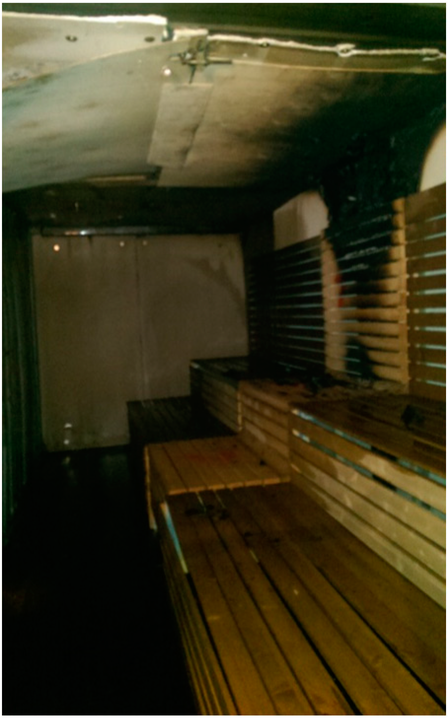
Figure 10). So, Test no. 7 can be regarded as the worst-case scenario, with ventilation and area coverage of the nozzles embodying the challenge: the former drives more oxygen that feeds combustion reaction, while the latter deserves appropriate design and selection to meet the requirements from the specific scenario. This aspect becomes apparent by comparing the extent of burned surface at the end of Test no. 7 (
Figure 12) with that at the end of Tests no. 2 and 3 (
Figure 11). On the other hand, the comparison between ceiling and bench temperature for Test no. 5 appears poorly significant, since the respective maxima were far lower than wood-ignition temperature. So, a gap between benches and behind the wall did emphasize fire spread onto the solid surfaces, even though it certainly made oxygen available in that region. In fact, the flames exhibited a rather vertical development, so water droplets were able to suppress them by convective flame cooling [
17] once the discharge was activated.
The heat flux incident onto the hot-plate thermometer is shown in
Figure 13 as a function of time for all the performed experiments; in that plot, the time reference (0) corresponds to discharge activation, thus highlighting fire history before (free burn) and after that (water-mist discharge). Even though heat-flux profiles present a certain degree of noise, their trend firmly supports the observations proposed out of the analysis of gas and surface temperature. All the profiles exhibit an initial increase during the free-burn phase, followed by a rather steep decrease upon discharge activation; a clear instance of regrowth appears for the heat-flux trend of Test no. 7 prior to reaching final decay, which is related to reignition at the ceiling combined with the still-burning timber bench.
Therefore, hot-plate thermometry proved overall quite effective in capturing both the free burn and the suppression phase, whether achieved or not.
As the most significant observation, all temperature trends featured a dramatic decay upon discharge, which is typical of high-pressure (i.e., greater than 35 bar [
27]) water-mist systems when successful in suppressing a fire: the spray momentum is instrumental in allowing droplets to reach the hot surfaces and realize surface cooling, also emphasized by surface-temperature trends (
Figure 9 and
Figure 10) while performing flame cooling, as shown in the trends of Test no. 1 (
Figure 8) [
6,
7,
17]. Overall, only a small portion of the drywall boards at the ceiling was involved by the fire and resulted as mildly blackened at the end (
Figure 11a).
However, in Tests no. 3 and 7, flames engulfed the ceiling considerably, and gasification was comparatively more intense (
Figure 11b and
Figure 12), which hints at the prolonged free burn (Test no. 3) and at the most challenging conditions among those tested (Test no. 7).
Table 3 presents a summary of all the experimental outcomes, with all the time values referring to ignition of the heptane pool fire as the origin. The reported data support the ability of the designed system to control and, overall, suppress the fire over the various tested scenarios. The results from Tests no. 1 and no. 2 do not significantly differ, which allows consideration of the location of the ignition source as almost irrelevant in achieving successful suppression. The presence of smoldering materials at the end of some experiments (Tests no. 4 and 7) strengthens the concept of thermal control and suppression as the results from water-mist discharge, rather than extinction; that is particularly apparent as the worst-case scenario is concerned. Overall, the timber-bench damage ratio was always kept below 5%, with the maximum (3%) occurring in Test no. 3, where discharge activation was delayed on purpose. As expected, the wood-crib fire extinction required a longer time in the tests, where initial room temperature was made consistent with that of actual saunas (about 80 °C); interestingly, that did not translate into wood-crib and bench damage ratio higher than in the other tests, which emphasizes the performance by the developed system. The heat detector issued its alarm at a time reasonably consistent with the whole test series. However, the time was somewhat longer in Test no. 5: the smaller involvement of the benches with fire as a result of the air gap between benches and wall arguably yielded a slower fire evolution, also shown by temperature trends in
Figure 10; therefore, the threshold triggering the alarm signal was reached later. In general, the location of the ignition source, presence of drywall boards behind benches, and presence of a gap between benches and the wall behind were not determining factors; higher initial room temperature and ventilation led to an impact on some aspects (i.e., surface temperature, extent of involved materials, and regrowth/reignition phenomena); discharge activation time proved relatively significant with regard to gasified (burnt) mass, which suggests that early activation is instrumental in containing the loss of property, even when high-pressure water mist is operated.
As recalled in
Section 2, the cost associated with full-scale fire experiments is not negligible, which often makes repeating tests hardly sustainable. Moreover, the inherent statistical nature of turbulent-flame evolution shall be taken into account when assessing repeatability in such experiments. Nevertheless, a qualitative comparison between the free-burn phase of Tests no. 2–4—expressed by the temperature profiles in
Figure 9—represents a certain degree of repeatability: even though the initial slope of surface temperature at the benches is more variable than that of surface temperature at the ceiling, overall consistency is displayed. Moreover, the already mentioned consistency between maxima of surface temperature at the benches also suggests that the behavior of unhindered fire is somewhat repeatable in the proposed experimental setup. As for the suppression phase, the performed tests (
Table 2) overall feature different conditions, which does not allow proposing any conclusive observations on repeatability in that regard. Nevertheless, Tests no. 2 and 4—actually conducted under the same experimental conditions—exhibit very similar surface-temperature trends (
Figure 9) and similar results in terms of damage ratio and wood-crib extinction time (
Table 3). Those outcomes give evidence that even suppression may be identified as a repeatable mechanism, at least to a certain extent.
4. Conclusions
A series of experiments was devised and conducted to assess the ability of water-mist systems to control and suppress fires within a sauna scenario; the approach and the variety of considered parameters appear unprecedented in the open literature, especially as the study focuses on such a particular application. The compartment was designed to reproduce a sauna where the failure of an electrical heater causes a fire; the design of the employed fire-protection system—combining detection and discharge—and the test procedure were developed, as inspired by recognized standards [
26,
27,
29], even though no specific guidance is currently available for this scenario. Several measurements were taken to assess, quantitatively, the performance of the discharge system. Notably, gas and surface temperature were evaluated at various locations of interest, both at the ceiling and at the benches, together with employing a hot-plate thermometer to quantify heat flux emitted through the fire evolution. Those quantities were deemed representative of HRR, thus allowing one to distinguish unsuccessful from successful suppression. A wood-crib fire accelerated by a heptane pool fire was used as the ignition source, and its extinction was also evaluated as a mark of achieved suppression, since its location was arguably the hardest to reach by released water. Damage ratio was measured for bench and wood crib; qualitative evaluation of fire spread by comparing pre- and post-fire photos was performed. A number of design parameters were varied through the test series towards an identified worst-case scenario: location of the ignition source, air gap between benches and wall, initial room temperature, ventilation, nozzle-to-wall distance, and activation of the discharge.
Overall, the designed water-mist system was capable of controlling and suppressing the fire in all tests, with evidence of sharp temperature decay upon release of the spray at all sampling locations. The wood-crib fire was extinguished in all the performed experiments. The presence of smoldering materials at the end of some tests corroborated the reference to suppression, rather than extinction, as the main scope of water-mist technology. In general, the ceiling was mildly involved with the fire, even though a significant extent of its surface resulted as blackened in the case of prolonged exposure to free burn (i.e., delayed discharge activation), and this related to the worst-case scenario (i.e., initial room temperature above 80 °C, natural ventilation ongoing, and larger distance between nozzles and benches). The location of the ignition source, as well as the presence of drywall boards behind timber benches, together with a gap between benches and the wall behind the sauna, did not prove critical in determining the degree of success in suppression. A discharge governed by the feedback from a heat detector was effective in containing the timber-bench damage ratio; even though it never exceeded 3% over the whole series, a delayed activation of the discharge yielded higher damage, which emphasizes the need for early activation, even when a high-pressure water mist discharge is operated. Initial room temperature—aligned to that of actual saunas in some experiments—does not appear a determining factor, even though surface-temperature profiles demonstrate that the higher room temperature, the more prone the materials are to be involved with fire. The worst-case scenario showed that natural ventilation and a larger distance between nozzles and timber benches did not prevent the system from effectively suppressing the fire, but may have yielded regrowth and reignition phenomena, as they were observed at the ceiling surface while the benches were still burning. Hot-plate thermometry also proved able to capture those instances. Even though the timber-bench damage ratio did not vary with respect to the other tested conditions, the test run under the worst-case scenario suggests that water-mist systems in saunas may be combined with self-closing doors, thus limiting oxygen influx due to natural ventilation.
This work proved water-mist technology capable of controlling and suppressing a fire occurring in a sauna scenario, and it also provided designers with guidelines and—arguably an even more significant contribution—with a framework that allows relating the discharge system with both structural and ambient parameters within the compartment. As expected even for water mist, the effectiveness of an active fire-protection system is emphasized by early detection. To this end, inserting heat detectors is strongly recommended. However, the use of vision-based fire detection—currently a subject of many studies [
37,
38] and a very promising approach—may also be strategic, especially when combining feedback from surveillance systems with image-processing algorithms that allow identification of the presence of smoke and flames, together with assessing the fire size.


