1. Introduction
Concrete is the most widely used construction material and a significant contributor to the impact of construction on the environment [
1]. Facing the fact that future construction will require more and faster-erected buildings comprising less material, the concrete construction industry urgently needs resource-efficient and sustainable lightweight structures [
2,
3]. A promising approach is the optimized arrangement of concrete hollow bodies inside of the components [
2]. This arrangement follows the principle of a fully stressed design, where concrete hollow spheres are placed in areas with low utilization. On the example of hollow sphere beams, previous research has shown that this technology enables up to 50% of material savings compared to solid ones while maintaining the same flexural capacity [
4]. Despite the established use of hollow core or hollow sphere systems in construction, the design regulations for such structures are not fully covered in construction standards such as Eurocode 2-2 or DIN 4102-4. This indicates the need for structural investigations on hollow sphere components subjected to fire.
In this paper, the flexural capacity of a solid slab and a hollow sphere slab exposed to fire are evaluated and compared. All components are designed using the general geometric thresholds provided by [
5,
6] for fire resistance of up to 90 min. The flexural capacity is determined in two steps: First, the temperature profile of the components is identified on a cut-out of the slab with a surface area of 1 m × 1 m using a finite element (FE) simulation in ABAQUS. Subsequently, a stand-alone Excel-tool is used to calculate the elongation curve in the slab’s weakest cross-section that results in the highest possible flexural moment. Throughout these two steps, the physically nonlinear and temperature-dependent material behavior of concrete and steel is considered. This paper shows that the valid standards for fire design [
5,
6] are applicable to the design of hollow sphere slabs as they are for solid slabs, thus allowing for a more sustainable approach to future building constructions.
This paper only considers simulations of the fire behavior of solid and hollow sphere slabs by comparing simulation results with heat profiles in slab elements according to Eurocode 2-2. Within this framework, we initially restrict ourselves to the flexural capacity of statically determined systems, knowing that the shear force capacity is often the dominant criterion [
7]. These preliminary investigations fit into a broad research context of hollow sphere slabs. In the following, the shear force capacity as well as statically indeterminate systems in case of fire will be considered. In the future, fire tests will be necessary to fully validate the simulation results.
2. Methods and Tools
The flexural capacity is investigated in two steps: First, the component’s internal temperature profile in case of fire is simulated based on the heat transfer theory. For this purpose, the simulation parameters and the temperature-dependent material properties of concrete and reinforcing steel according to [
5,
8] are used. In a second step, the temperature data from the FE simulation allow for the determination of the maximum flexural moment of a structural element. This is performed using a cross-section analysis based on structural mechanics, considering nonlinear, temperature-dependent material parameters.
2.1. Thermal Analysis
The purpose of thermal analysis is, among other things, to determine the temperature profile in a building component. This section describes the temperature distribution on the fire-facing side including heat transfer parameters, heat penetration into the concrete, and temperature-dependent material parameters of concrete and steel.
2.1.1. Temperature on Fire-Facing Side
The basic equation for the temperature distribution in the component’s interior is based on the Fourier approach, describing transient heat conduction in solids [
8]:
where
is the temperature in Kelvin,
t is the time in seconds, and
is the thermal diffusivity in m
2/s calculated as
where
is the thermal conductivity in W/(mK),
cp is the specific heat in J/(kgK),
is the bulk density in kg/m
3, and the variables
x,
y, and
z are the space coordinates in meters.
The solution of this equation is performed using ABAQUS finite element software. For the calculation of concrete components, temperature-dependent material properties such as thermal conductivity, specific heat
, and bulk density must be considered [
8].
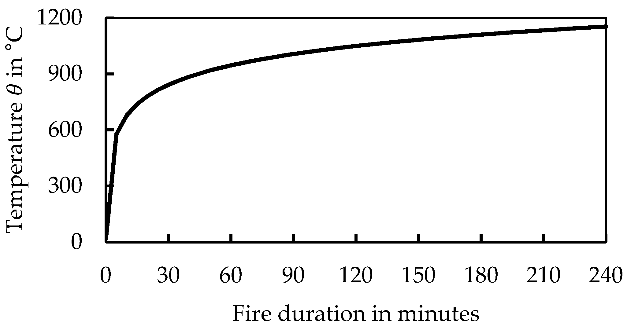
The unit—temperature—time curve for the hot gas temperature from [
8] is assumed for the fire-facing side (
Figure 1). The temperature increase in this curve can be calculated as a function of the fire duration t in minutes with the following equation:
For fire exposure, the heat flow into the component’s surface is calculated consisting of a convective and a radiative part. The convective part is defined by heat transfer coefficients and the temperature difference between the environment and the component’s surface. The radiative part consists of the emissivity of this surface, the radiation temperature of the environment, and the Stefan Boltzmann constant. Based on [
8] the heat transfer coefficient of concrete
. is defined as 25 W/m
2K and the emissivity
as 0.7.
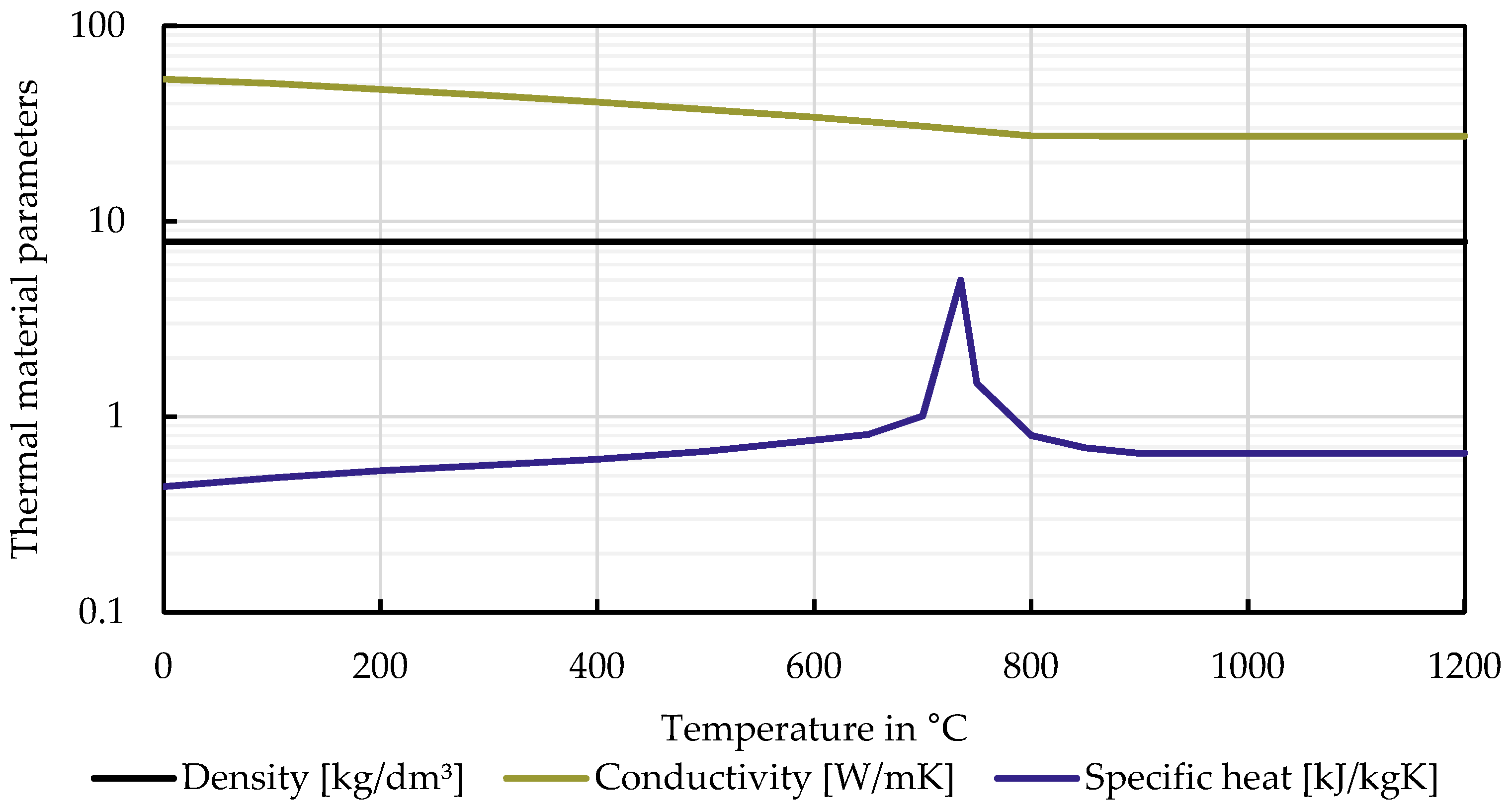
2.1.2. Temperature-Dependent Material Properties of Concrete and Steel
The thermal conductivity
describes the heat transfer through a body in the case of a temperature gradient [
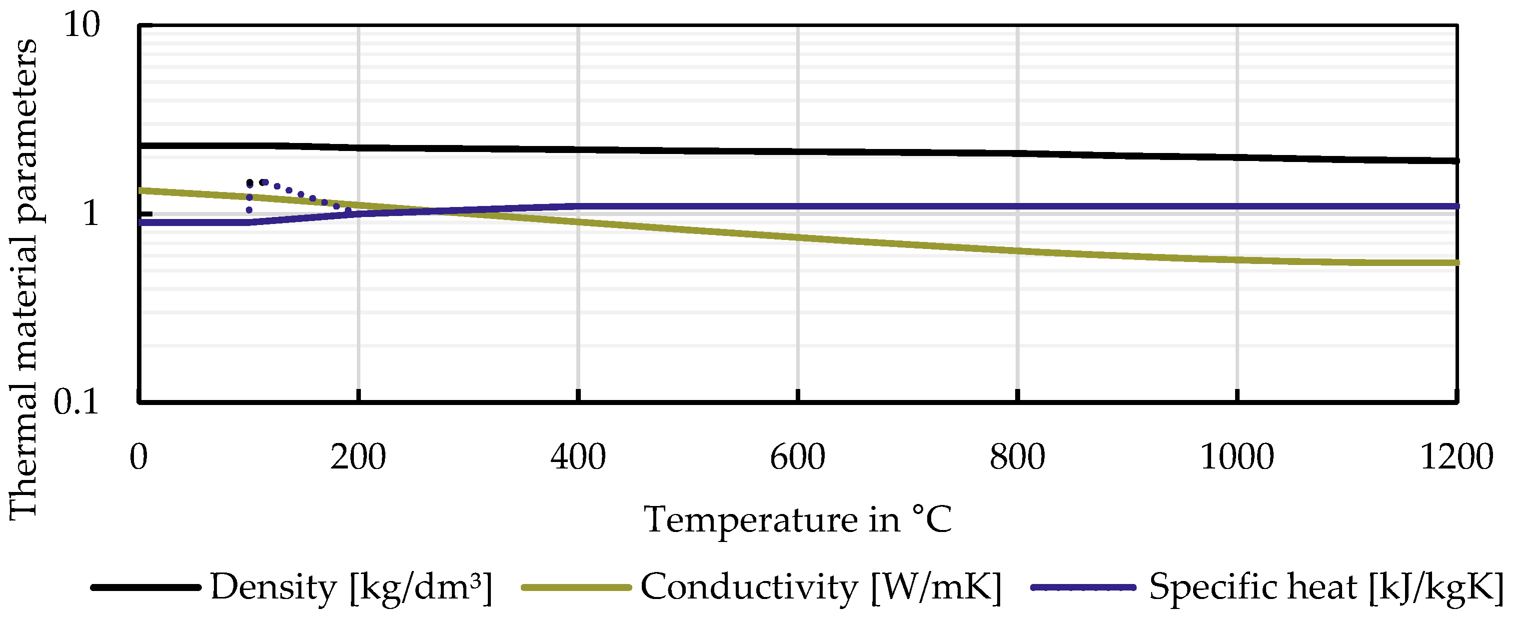
9].
Figure 2 shows, among other things, the variation of thermal conductivity as a function of temperature for concrete during fire exposure. As the temperature increases, the thermal conductivity of the concrete decreases. The thermal conductivity of steel, illustrated in
Figure 3, is significantly higher than the one of concrete and is calculated according to [
10].
The specific heat
is a measure for the capacity of a material to store thermal energy [
9]. Next to the thermal conductivity,
Figure 2 shows the course of the specific heat of concrete as a function of the temperature. In the range of 100 °C–200 °C, the curve peaks due to the evaporation of the remaining pore water in the concrete, resulting in higher heat energy demand [
8]. The specific heat of steel in
Figure 3 increases between 700 °C and 900 °C and is calculated according to the Eurocode 3 [
10].
Furthermore, the bulk density of concrete decreases slightly when the temperature reaches 100°C because the water in the concrete starts to evaporate [
8], whereas the bulk density of steel keeps constant at 7850 kg/m
3 [
10].
2.1.3. Simulation Parameters
The thermal analysis rests on the thermal conductivity, specific heat capacity, and bulk density, all of which are functions that depend on the temperature for both concrete and steel [
5]. The temperature profile strongly depends on the unit—temperature—time curve. Further analysis parameters were taken from [
5] and were adjusted to result in results on the safe side (
Figure 4 and
Table 1). The air void effect was considered, but not taken into account, as the influence was negligible.
2.2. Mechanical Analysis
A stress–strain-based cross-section analysis is performed to calculate the resisting flexural moment of the examined slab type. According to the works of Reick [
11] and Reichert [
12], an Excel-Tool was developed for this purpose.
From the thermal analysis, the Excel-Tool obtains the areas of each mesh element adjacent to the considered cross-section, the coordinates of the area centroid, and the average temperature in the element. Based on this, for each element, the strain caused by the temperature expansion is determined according to [
5].
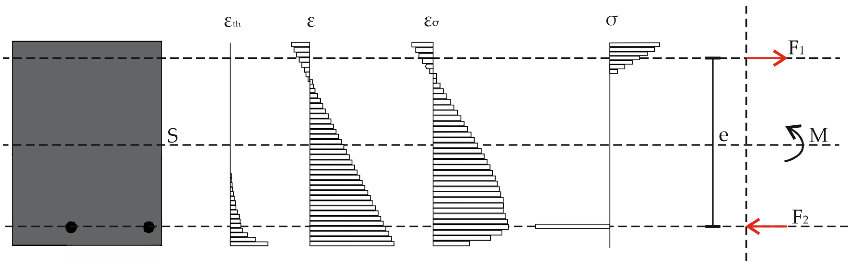
The calculation of the resisting flexural moment is performed iteratively by varying the strain. It is assumed that Bernoulli’s hypothesis of plane cross-sections is also valid in the case of fire and the strain is thus distributed linearly over the height of the cross-section. The total strain
. consists of three components: the thermal expansion
, the strain due to constraint, and the strain due to loading. The strain due to thermal expansion does not affect the stress and is deducted from the total strain resulting in the stress-generating strain
[
8]:
with the depth
z and the curvature
[
8].
According to the parameters of the stress–strain relationship provided in Eurocode 2-2, the corresponding stresses of concrete and steel are determined at the center of gravity of the mesh elements. For concrete, the values according to Table 3.1 and Figure 3.1 in the Eurocode 2 [
5] are used. The values for steel are based on Eurocode 2 [
5] as well and are in accordance with Table 3.2a and Figure 3.3. The corresponding forces are calculated and combined into a balanced pair of compression and tension forces allowing for the determination of the maximum flexural moment (
Figure 5). The total strain distribution is determined iteratively, allowing the calculation of the upper and lower strain to maximize the flexural capacity while keeping an equilibrium of forces. The following strain limits are selected for concrete and steel, respectively: the concrete strain must be less than 0 and greater than −0.0029, whereas the steel strain must be greater than 0 and less than 0.0225.
2.3. Fire Resistance Classes
The fire resistance classes depend on the possible fire resistance duration and further classification criteria [
13]. Concrete slabs are “load-bearing, room-enclosing building components” [
5] with the decisive criteria R for load-bearing capacity, E for space closure, and I for insulation, which need to be met for a given period. The criterion ‘R’ is assumed to be satisfied if the load-bearing capacity is kept for the demanded fire resistance duration [
5]. If the maximum temperature rise of the fire-averted surface does not exceed 180 K and the average temperature rise is less than 140 K, then criterion ‘I’ is met according to [
5]. The criterion ‘E’ cannot be demonstrated using a cross-sectional approach and is thus not considered in this paper.
3. Test Program
This chapter describes the structural system, the load assumptions, and the slab cross-sections used in the fire simulations for conventional solid, as well as hollow sphere slabs.
3.1. Structural System, Load Assumptions, and Time of Fire Exposure
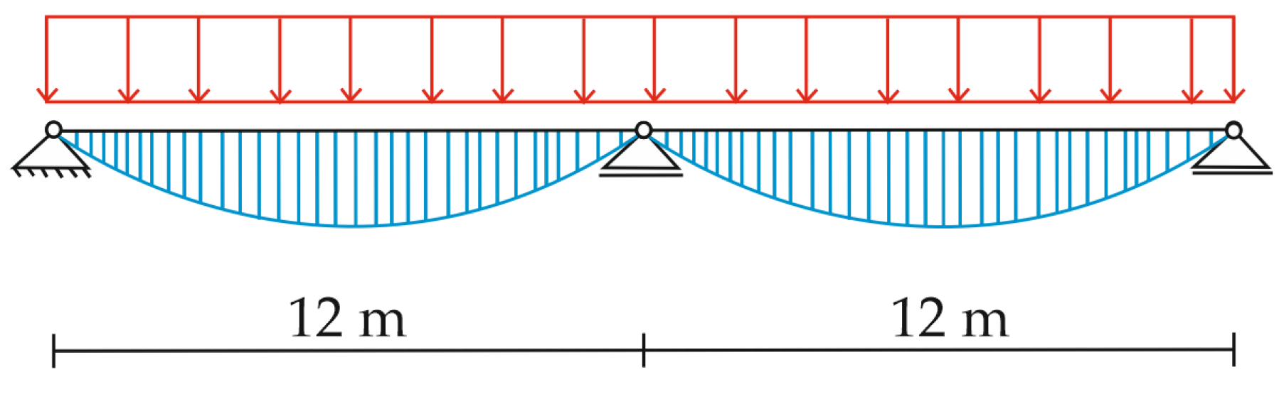
This contribution investigates statically determined slab systems. The structural system consists of two simply supported slabs with a span of 12.0 m and a width of 1.0 m each (
Figure 6). The load assumption considers the component’s dead-weight, extension loads of 1.5 kN/m
2, a partition wall surcharge of 1.2 kN/m
2, and a live load for, e.g., museum use of 5.0 kN/m
2. The slab height is determined from the provided boundary conditions and on the basis of the verification of the bending slenderness [
14].
The moments and forces are calculated according to [
15] with a partial safety factor of
γGA = 1.0, and
ψQA = 0.5 for permanent and live loads, respectively. The calculation is performed for 30, 60, and 90 min of fire exposure.
3.2. Test Specimens
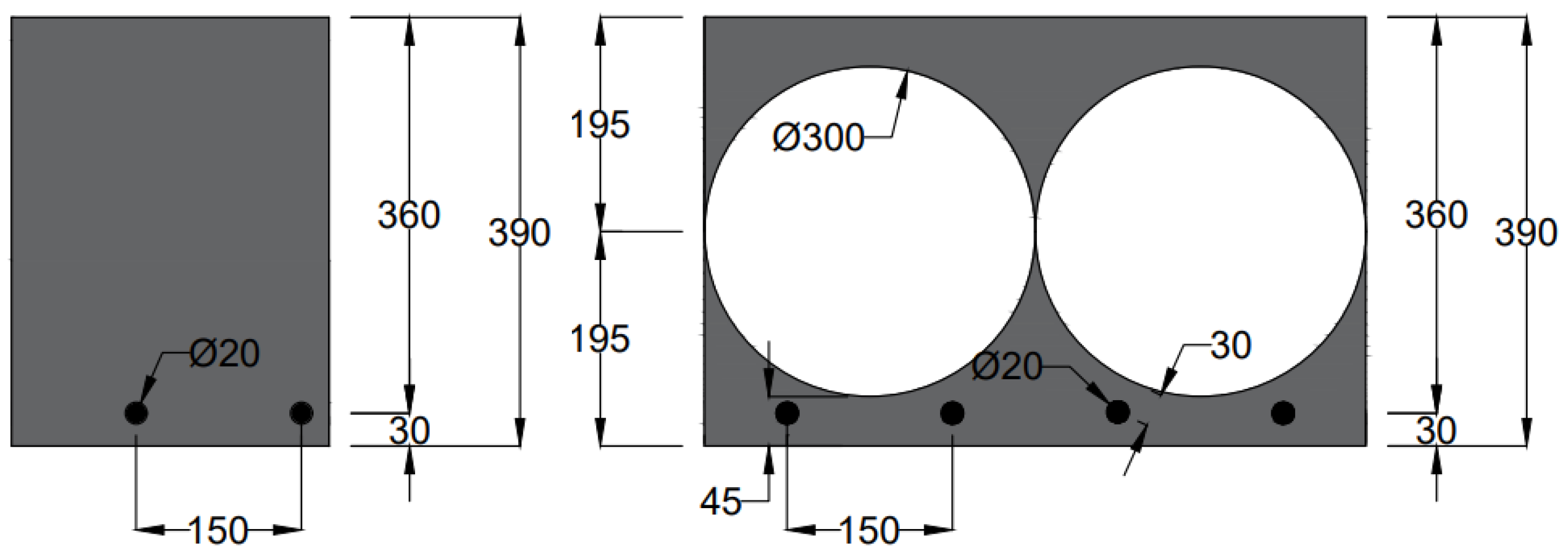
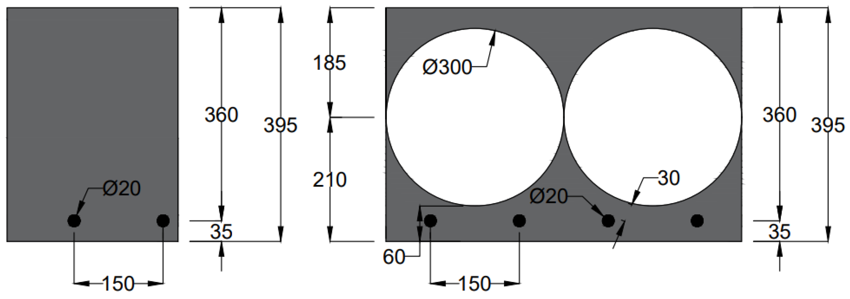
The thermal analysis is conducted on an exemplary cut-out of the respective slab with a surface area of 1 m × 1 m. In accordance to [
14], the static effective depth of the cross-section is pre-dimensioned for compliance with the general limit criterion for bending slenderness (
Figure 7 and
Figure 8). For the arrangement of hollow spheres and the center distance of the reinforcement, the investigations are carried out based on [
5,
6] in variants. In both cases, the respective minimum concrete coverages are assumed for a fire resistance duration of 90 min. Thus, considering a constant static effective depth and the corresponding minimum concrete covers, the total height of the component in
Figure 8 increases by 5 mm, and the hollow sphere layer is shifted out of the gravity axis of the cross-section.
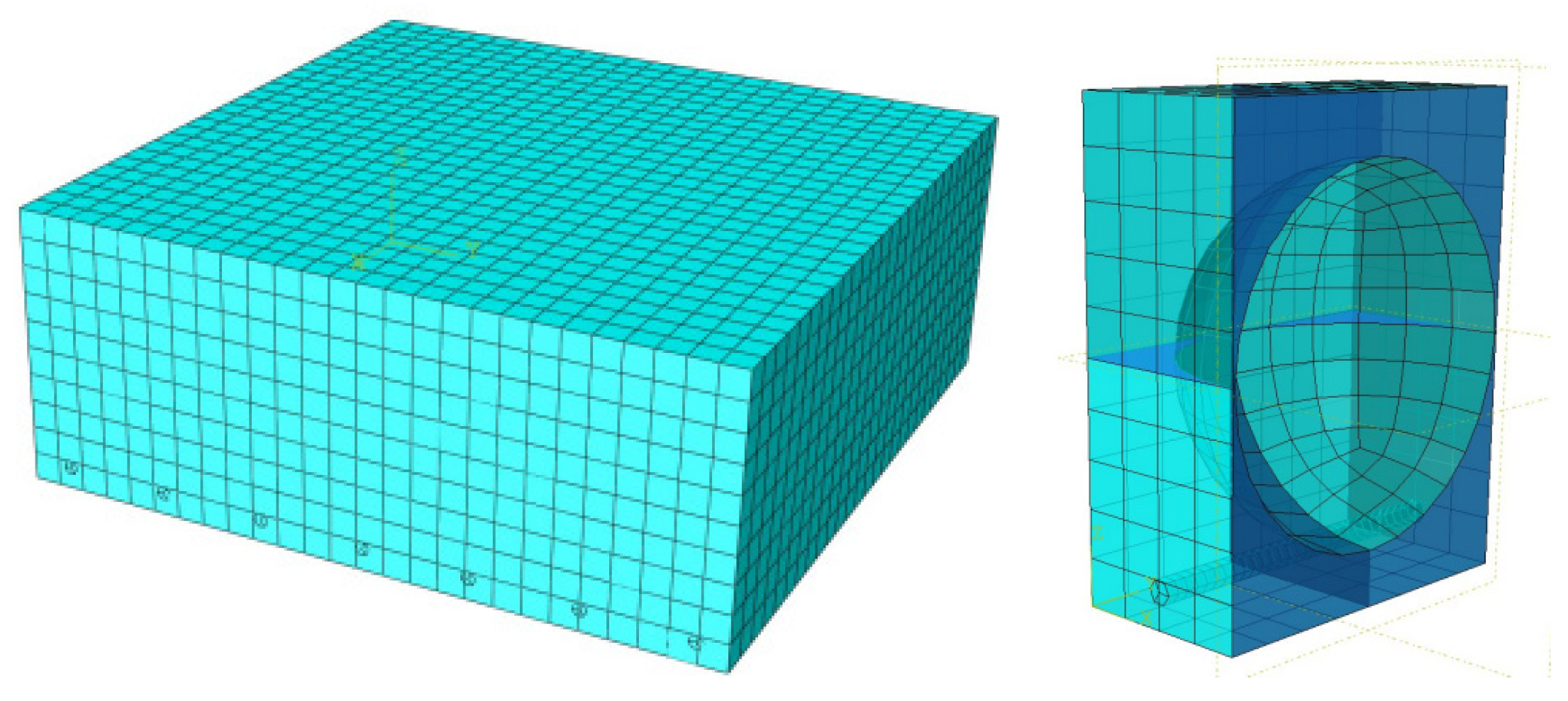
For the thermal analysis and the subsequent calculation of the maximum flexural capacity, a concrete C30/37 is assumed. The longitudinal reinforcement consists of seven conventional B500S rebars with a diameter of 20 mm and a horizontal spacing of 150 mm from each other. The embedded hollow spheres have a diameter of 300 mm and are placed in single-layer cubic packing, leading to a mass reduction of approximately 38% compared to the solid reference slab. In addition, the thermal analysis with ABAQUS is based on hex elements with an identical mesh width of 38 mm for both slab types (
Figure 9).
4. Results
4.1. Solid Slab
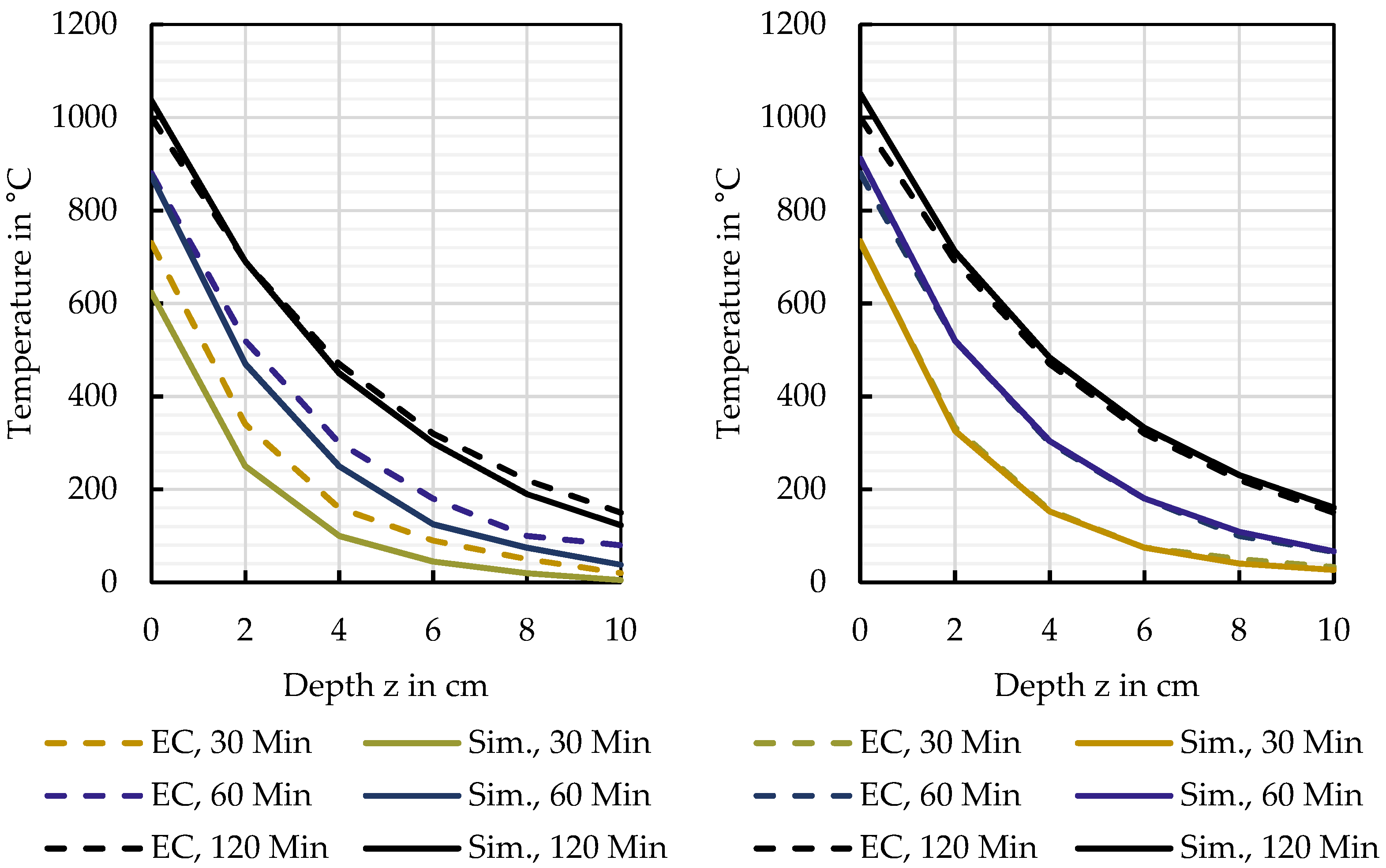
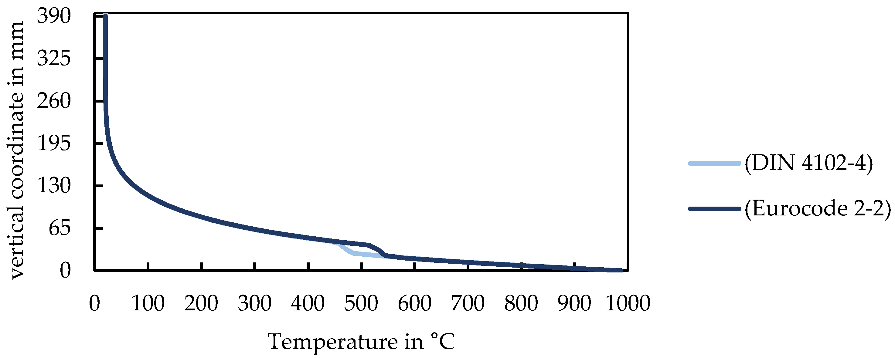
The results of the thermal analysis for the solid slab with dimensions based on [
5,
6] are shown
Figure 10 and
Figure 11. The temperature curves in
Figure 10 run identically and change with time so that after 90 min the heat penetrates deeper into the cross-section. In the reinforcement area, the temperature curve drops downward due to the high thermal conductivity of steel. Thus, the reinforcement conducts the heat directly to the surrounding concrete. In the unreinforced areas, the temperature curve remains continuous over the cross-section’s height [
16]. After a fire exposure of 90 min, the solid slab retains a resisting flexural moment of 257.1 kNm/m and 258 kNm/m with dimensions based on [
5,
6], respectively. Those values are calculated based on the mechanical analysis. Further fire exposure causes a tensile failure of the reinforcement.
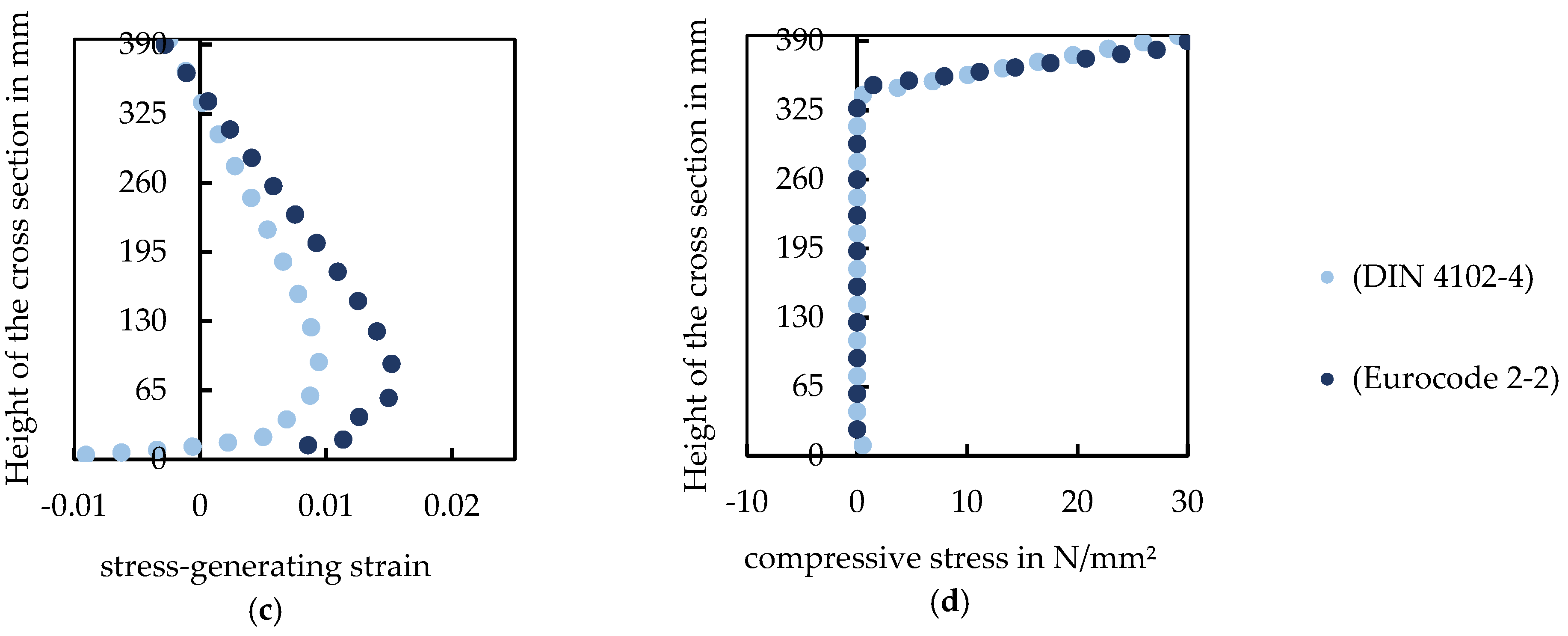
In the bottom area of the cross-section, and hence on the fire-exposed side of the component, the thermal strains reach their maximum (
Figure 12a). Furthermore, the total strain has a linear distribution, with zero-crossing at approximately 339 mm starting from the bottom edge of the component (
Figure 12b). The stress-generating strain, shown in
Figure 12c, is obtained by subtracting the total strain from the thermal strain. The compression in the top area of the cross-section increases slightly. Due to the stress-generating strain, compression stresses (
Figure 12d) develop in the upper region of the cross-section.
4.2. Hollow Sphere Slab
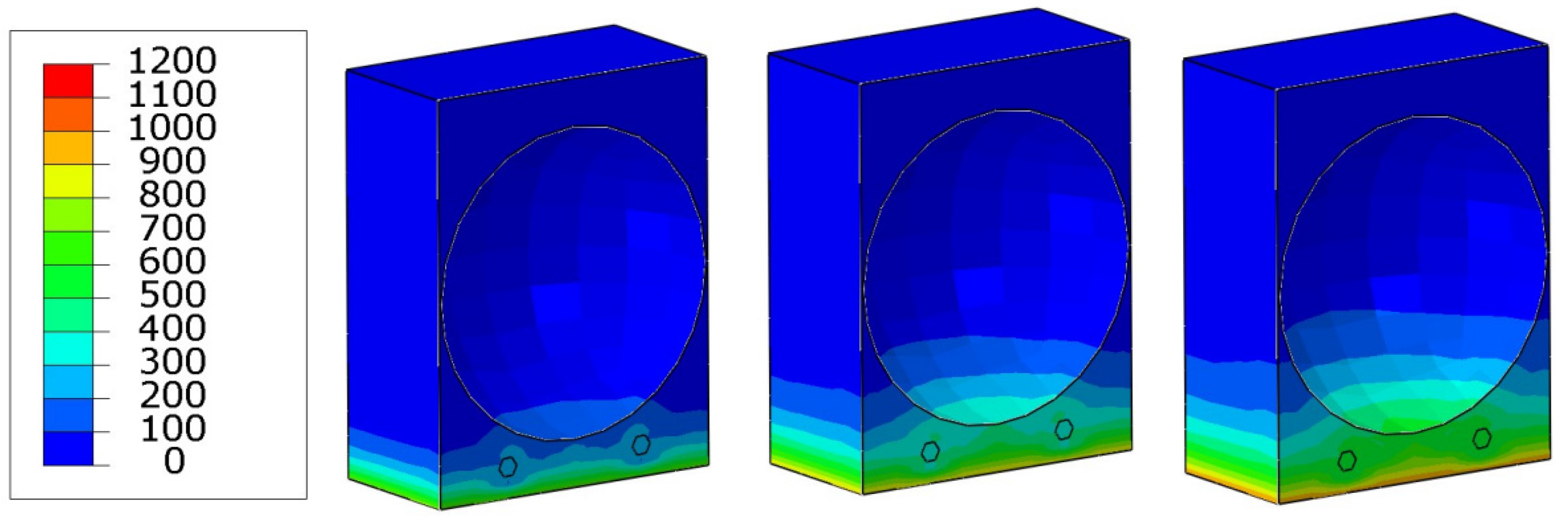
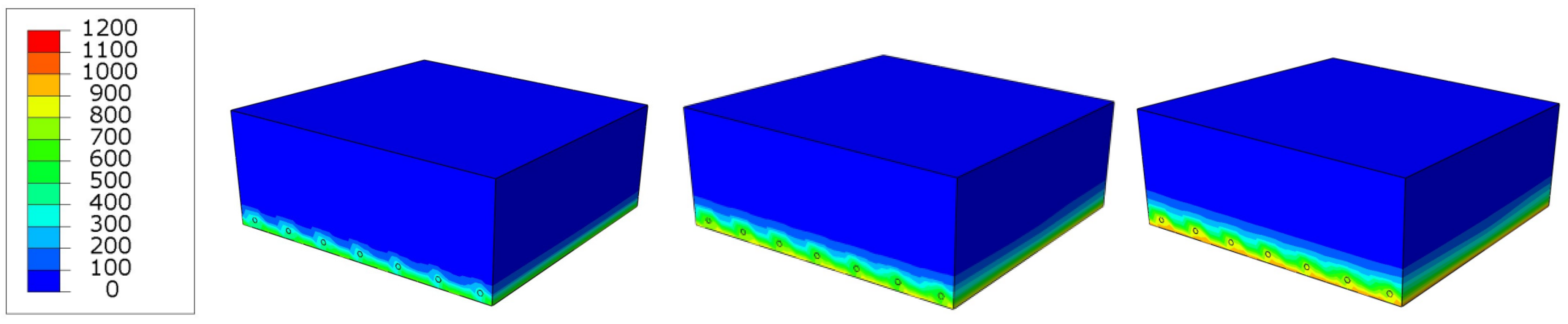
The temperature profiles of the hollow sphere slab after 30, 60, and 90 min fire exposure are pictured in
Figure 13 with dimensions based on [
5]. Here, the heat accumulation occurs because the cavities prevent its dissipation. As a result, the area below the hollow spheres warms up faster than its environment [
17]. After a fire exposure of 90 min, the hollow sphere slab possesses a resisting flexural moment of 248.5 kNm/m and 253.5 kNm/m with dimensions based on [
5,
6], respectively. As for the solid slab, further fire exposure causes a flexural tension failure.
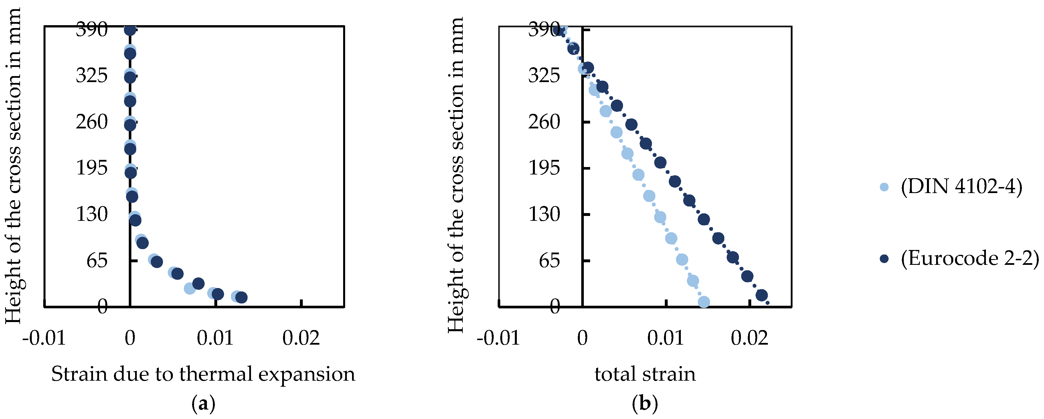
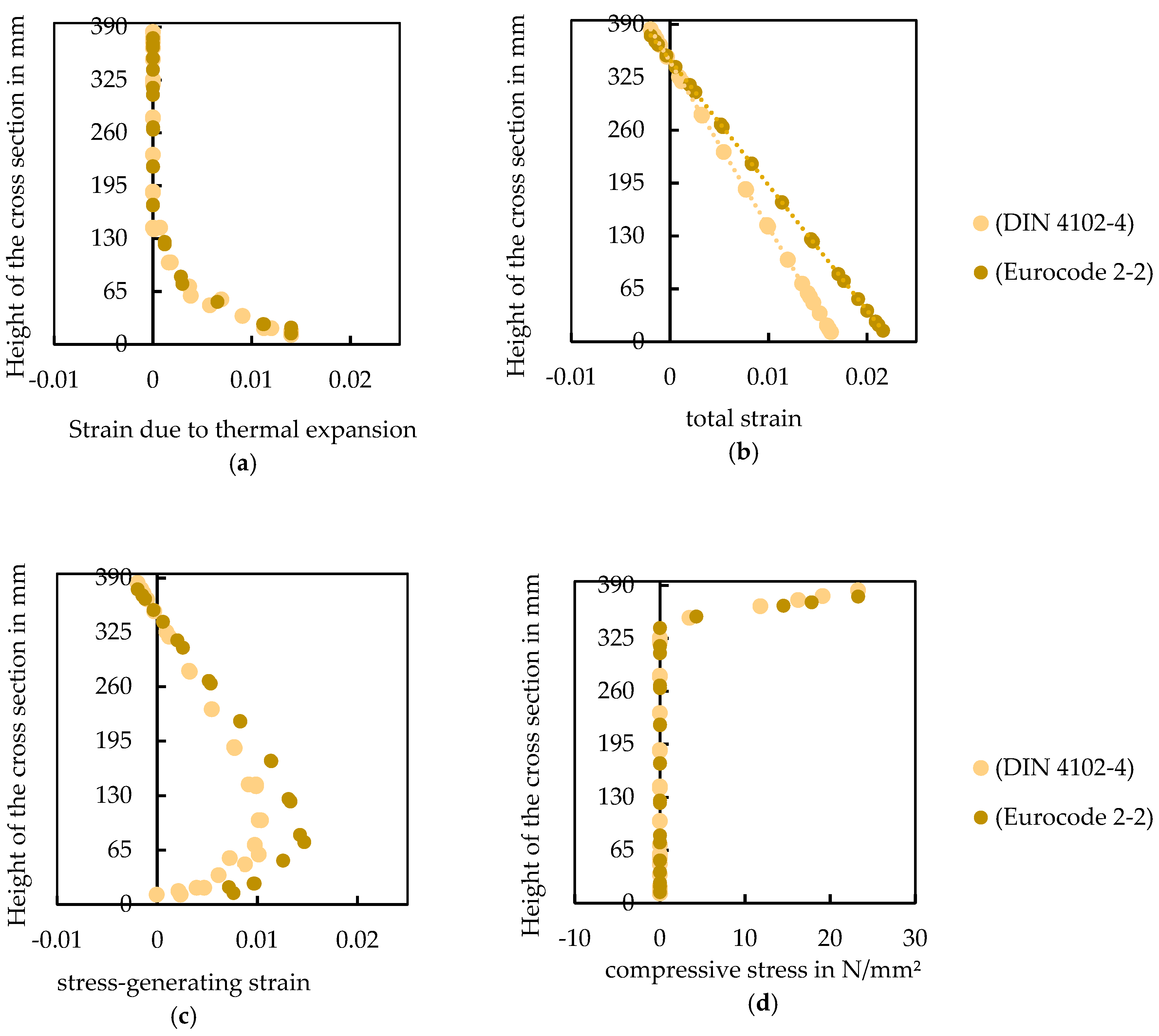
The stress and strain profiles for the two hollow sphere variants after 90 min of fire exposure are provided in
Figure 14. The thermal strain (
Figure 14a) is highest in the bottom area of the cross-section because this side is flamed. The total strain (
Figure 14b) has a linear trend. The stress-generating strains (
Figure 14c) cause concrete compression stresses (
Figure 14d) in the top area. The compression zone is not intersecting with the hollow spheres. In addition, the maximum strain is at the height of 75 mm, starting from the lower edge of the component.
5. Discussion
Table 2 shows the dead weight of the different slab types with the dedicated design moment and points out a correlation: the higher the dead weight, the higher the design moment. Thus, an advantage of the hollow sphere slab becomes apparent; the permanent loads are significantly reduced due to mass savings.
In addition, the flexural resistances for the slab types after 30, 60, and 90 min fire duration are shown in
Table 3. All values are calculated based on the mechanical analysis showing comparatively similar flexural capacities. Both solid and hollow sphere slabs withstand a fire duration of 90 min, proving the design guidelines [
5,
6] to be valid. Furthermore,
Table 4 presents the utilization of the flexural resistance in percent. With increasing fire duration, the utilization also increases for all slabs.
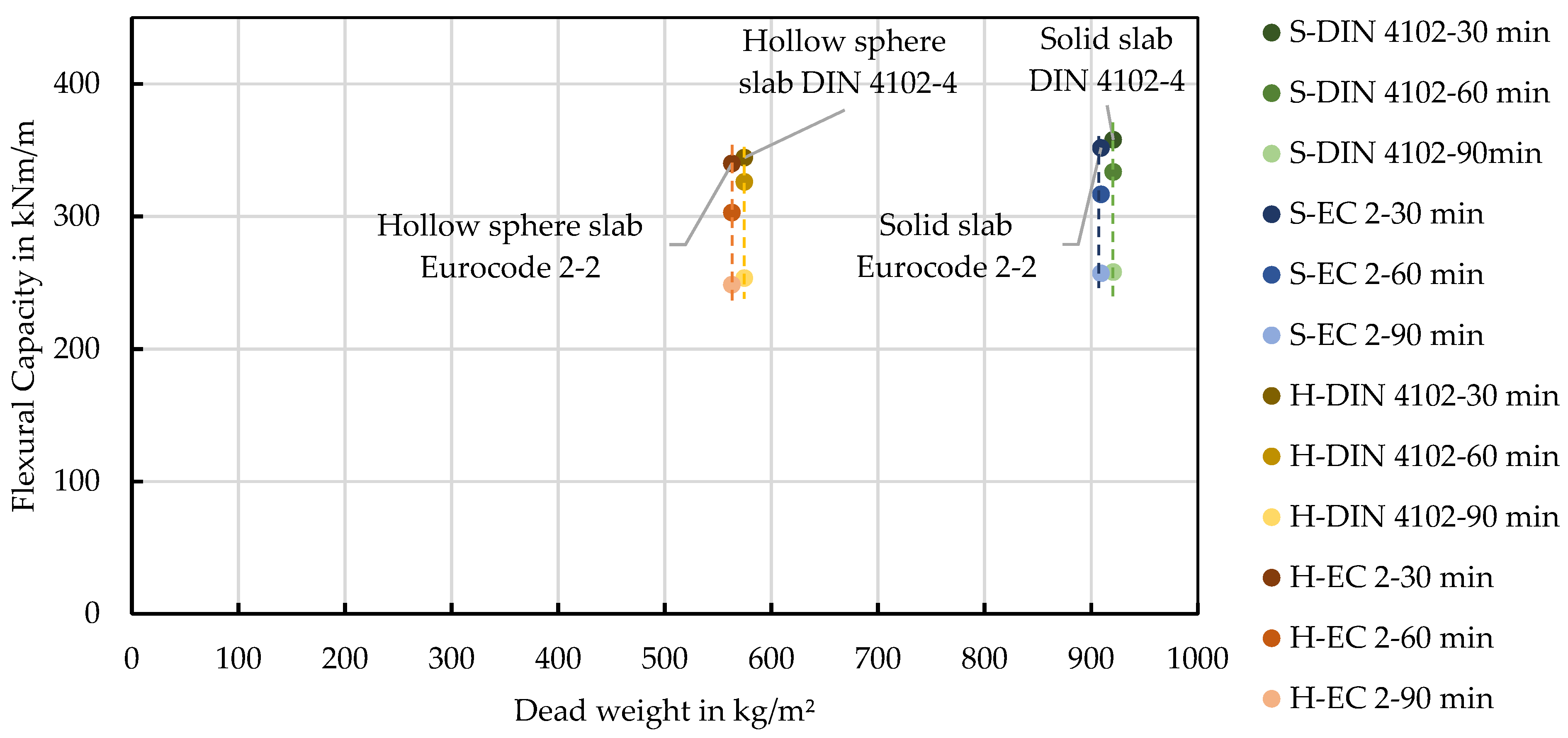
In
Figure 15, the flexural capacity of the investigated solid and hollow sphere slabs are printed over the dead weight and compared among each other. During flame impingement, the flexural capacities decrease for all slab types with only minor deviations. However, the difference in dead weight is significant. Compared to the solid reference system, the hollow sphere slab has about 38% less mass while maintaining a comparable flexural capacity. A final comparison of the specific dimensioning according to [
5,
6] shows that increasing concrete covers led to higher flexural capacities for shorter fire durations. However, this evident relationship is relativized for a fire exposure of 90 min.
6. Conclusions
In this paper, the flexural capacities of solid and hollow sphere slabs exposed to fire were evaluated and compared. It has been shown that a design based on Eurocode 2-2 or DIN 4102-4 is valid for both systems and that the minimum dimensions from the tabular methods can be used as an aid.
Furthermore, the investigation results show that hollow sphere slabs exhibit a significantly lower mass compared to the solid reference, thus the embedded hollow spheres have no negative influence on the flexural capacity in case of fire.
However, it must be considered that this paper only dealt with simply supported slab systems and simulations. Further investigations on indetermined ones and fire tests are necessary and will be carried out in following studies.
In a nutshell, hollow sphere slabs are sustainable alternatives to solid ones because of their lower resource consumption and greenhouse emissions.
Author Contributions
Conceptualization, O.G. and D.N.; data curation, O.M. and O.G.; formal analysis, O.M.; investigation, O.M.; methodology, O.M., O.G. and D.N.; project administration, O.G. and L.B.; software, O.M. and O.G.; supervision, O.G., D.N. and L.B.; validation, O.M.; visualization, O.M.; writing—original draft, O.M.; writing—review and editing, O.G., D.N., D.K. and L.B. All authors have read and agreed to the published version of the manuscript.
Funding
The research published in this article is supported by the Deutsche Forschungsgemeinschaft (DFG, German Research Foundation) under Germany’s Excellence Strategy–EXC 2120/1–390831618. The authors cordially thank the DFG.
Institutional Review Board Statement
Not applicable.
Informed Consent Statement
Not applicable.
Conflicts of Interest
The authors declare no conflict of interest.
References
- Weidner, S.; Mrzigod, A.; Bechmann, R.; Sobek, W. Graue Emissionen im Bauwesen–Bestandsaufnahme und Optimierungsstrategien. Beton Stahlbetonbau 2021, 116, 969–977. [Google Scholar] [CrossRef]
- Schmeer, D.; Sobek, W. Gradientenbeton. BetonKalender 2019, 108, 455–476. [Google Scholar] [CrossRef]
- Blandini, L. Lightweight and Sustainable Concrete Structures: The ILEK Research Strategy. In Proceedings of the Fib Congress, Oslo, Norway, 12–16 June 2022. [Google Scholar]
- Sobek, W. über die Gestaltung der Bauteilinnenräume. In Festschrift Manfred Curbach; Scheerer, S., Ed.; Manfred Curbach: Dresden, Germany, 2016; pp. 62–76. [Google Scholar]
- DIN EN 1992-1-2; Eurocode 2: Design of Concrete Structures—Part 1–2: General Rules—Structural Fire Design; German Version EN 1992-1-2:2004 + AC:2008. Beuth Verlag GmbH: Berlin, Germany, 2010. [CrossRef]
- DIN 4102-4; Fire Behaviour of Building Materials and Building Components—Part 4: Synopsis and Application of Classified Building Materials, Components and Special Components. Beuth Verlag GmbH: Berlin, Germany, 2016. [CrossRef]
- Schmeer, D. Mesogradierung von Betonbauteilen: Herstellung und Tragverhalten von Betonbauteilen mit Integrierten Mineralischen Hohlkugeln. Ph.D. Dissertation, Universität Stuttgart, Stuttgart, Germany, 2021. [Google Scholar]
- Hosser, D.; Zehfuss, J. Brandschutz in Europa—Bemessung nach EC: Erläuterungen und Anwendungen zu den Brandschutzteilen der EC 1 bis 5 (Beuth Kommentar); Beuth Verlag GmbH: Berlin, Germany, 2012. [Google Scholar]
- Spille, J.; Zehfuß, J. Neuer Ansatz der thermischen Leitfähigkeit von Beton für die Brandschutzbemessung in EC 2. Bautechnik 2019, 96, 450–458. [Google Scholar] [CrossRef]
- DIN EN 1993-1-2; Eurocode 3: Design of Steel Structures—Part 1–2: General Rules—Structural Fire Design; German Version EN 1993-1-2:2005 + AC:2009. Beuth Verlag GmbH: Berlin, Germany, 2010. [CrossRef]
- Reick, M. Brandverhalten von Befestigungen mit Grossem Randabstand in Beton bei Zentrischer Zugbeanspruchung. Ph.D. Dissertation, Universität Stuttgart, Stuttgart, Germany, 2001. [Google Scholar]
- Reichert, M. Zur Bestimmung des Feuerwiderstands von Injektionsankern mit Variabler Verankerungstiefe in Beton. Ph.D. Dissertation, Technische Universität Kaiserslautern, Kaiserslautern, Germany, 2020. [Google Scholar]
- Post, M.; Schmidt, P. Lohmeyer Praktische Bauphysik: Eine Einführung mit Berechnungsbeispielen, 9th ed.; Springer Vieweg: Wiesbaden, Germany, 2019. [Google Scholar]
- DIN EN 1992-1-1; Eurocode 2: Design of Concrete Structures—Part 1-1: General Rules and Rules for Buildings; German Version EN 1992-1-1:2004 + AC:2010. Beuth Verlag GmbH: Berlin, Germany, 2011. [CrossRef]
- DIN EN 1990; Eurocode: Basis of Structural Design; German Version EN 1990:2002 + A1:2005 + A1:2005/AC:2010. Beuth Verlag GmbH: Berlin, Germany, 2010. [CrossRef]
- Mannsfeld, T. Tragverhalten von Stahlbetonflächentragwerken unter Berücksichtigung der Temperaturbedingten Nichtlinearität im Brandfall. Ph.D. Dissertation, Bergische Universität Wuppertal, Wuppertal, Germany, 2011. [Google Scholar]
- Albert, A.; Pfeffer, K.; Schnell, J. Hohlkörperdecken. BetonKalender 2017, 106, 519–549. [Google Scholar] [CrossRef]
| Publisher’s Note: MDPI stays neutral with regard to jurisdictional claims in published maps and institutional affiliations. |
© 2022 by the authors. Licensee MDPI, Basel, Switzerland. This article is an open access article distributed under the terms and conditions of the Creative Commons Attribution (CC BY) license (https://creativecommons.org/licenses/by/4.0/).


