Article

Numerical Simulation of Ethanol Air Diffusion Flame Quenching under Transverse AC Electric Field

1
School of Power Engineering, Naval University of Engineering, Wuhan 430033, China
2
School of Weapons Engineering, Naval University of Engineering, Wuhan 430033, China
*
Author to whom correspondence should be addressed.
Fire 2022, 5(6), 196; https://doi.org/10.3390/fire5060196
Submission received: 15 August 2022 / Revised: 27 October 2022 / Accepted: 8 November 2022 / Published: 17 November 2022
(This article belongs to the Special Issue Cable and Electrical Fires)

Abstract

:
The electric field fire extinguishing technology is an efficient, clean, and new fire extinguishing technology that can be operated at a long distance. In order to study the synergistic mechanism of “electric-flow-heat” in the process of transverse AC electric field fire extinguishing, the ionic wind formed by the influence of electric field on each charged particle during the burning process of ethanol–air diffusion flame is simulated by the non-premixed combustion model, and the experimental phenomenon of flame quenching in the transverse AC electric field is reproduced by means of numerical simulation. The accuracy of the numerical model was verified by comparing the temperature and flow velocity in the region obtained from the simulation with the data measured in the experiment. According to both simulated and experimental phenomena, we present a hypothesis of how the flame is quenched under the influence of an electric field. The next research directions are: (1) improving the accuracy of numerical simulation by building fine models; (2) studying the dynamic mechanism of real flames by particle image velocimetry technology.

1. Introduction

A flame is a weakly ionized plasma, in the role of the applied electric field its internal contains a large number of charged particles that will produce directional movement, and the formation of ionic wind, affecting the shape, stability, products, and other combustion characteristics of the flame [1,2,3,4,5]. The U.S. Defense Advanced Planning Agency (DARPA) has funded Harvard University’s White Edge Research Group to carry out research on electric field fire extinguishing technology [6], the results of which show that electric field fire extinguishing technology in limited space for small and medium-sized flame extinguishing effect is good but cannot be applied to and open areas of large firefighting work. While most of the ships and ships at sea are metal structures, the cabin space is closed and narrow, electric field fire extinguishing technology is an auxiliary means of fire extinguishing and because of its repeated work and no residual harmful substances after extinguishing [7,8,9], has a greater prospect of application on surface ships [10]. The current research on electric field-driven flame dynamics is mostly focused on the influence of the electric field on the combustion characteristics of small flames, and less on the medium-sized flame combustion characteristics affected by the electric field and focus on the electric field on the flame of the direction of the promotion of combustion, stable combustion effect research, electric field fire extinguishing effect of research is scarce. The study of the flame quenching process caused by the application of a uniform transverse AC electric field can help to understand the mechanism of electric field fire extinguishing and has important significance for the design and development of marine electric field fire extinguishing devices.
Drews et al. in the research group of Whitesides found that time-oscillating electric fields applied to plasmas in flames can produce stable gas flow. AC electric fields can manipulate flames at certain distances without the need for proximal electrodes [11,12].
Belhi et al. [13,14,15,16] studied the effect of the AC electric field on three different values of ion mobility for the same flame and the effect of negative ions on ion wind. It was concluded that negative ions play a crucial role in the formation of the ion wind effect, especially when a negative potential or alternating potential is applied to the electrode. Belhi also demonstrated the role of the ion wind effect in influencing flame kinetics by means of a detailed computational model with three-dimensional simulations to reproduce laminarly premixed methane–air native flames subjected to a transverse DC electric field in the saturated state. Based on the response of the laminar premixed methane–air native flame under this condition, it also proposes a skeleton mechanism to predict the fundamental properties of combustion in methane–air flames and an ionization optimization mechanism, which contributes to the study of the charged particle mechanism of hydrocarbon fuels.
In China, Yunhua Gan and Yanlai Luo [17,18,19,20] explored the combustion characteristics and chemical reaction mechanism of ethanol–air non-premixed combustion flame under the action of the electric field and proposed a detailed chemical reaction mechanism of ethanol–air flame combustion containing charged particles based on the skeleton mechanism of the basic properties of combustion in methane–air flame proposed by Belhi, which contains 64 components and 423 reactions. Di Renzo et al. [21,22] combined Belhi’s results to develop a spatial model of counter-current diffusion flame mixing fraction with a sub-breakdown electric field, and the computational results of this two-dimensional model agreed well with experimental data and significantly reduced computational costs. Research results [23,24], simulated the ethylene diffusion flame containing charged particles, and the flow of smoke particles in the flame under DC electric field.
Cui Wei carried out a theoretical simulation study on the effect of ions on the chemical kinetic properties of flames in methane–air premixed flames and the results further revealed that the effect of electric field on cyclonic flames is mainly caused by the ion wind effect which changes the position and shape of the flame surface [25]. Yan Limin conducted simulations and experiments on the interaction between electric field and small flame found that certain electric field conditions can strengthen the tiny-scale combustion, but too strong electric fields will blow out the small-scale flame [26].
In summary, the main research object of electric fields influencing flame is laminar small-scale flame, and the main research purpose is to enhance combustion stability of electric field. However, for the confined environments, such as naval ship cabins, the electric field fire extinguishing technology for large-scale flames has great application prospects.
In this study, the distribution of charged particles in ethanol flames is simulated by ANSYS FLUENT 2021R1 software; the electric field equations are integrated into the simulation to simulate the electric field force applied to the charged particles in the combustion region; the electric field extinguishing experiment is compared with the simulation of ethanol–air diffusion flames under the action of electric field to study the effect of electric field on the charged particles in ethanol–air diffusion flames and the flow field in the combustion region. The flame quenching phenomenon under the effect of transverse AC electric field was investigated.

2. Experimental Setup and Methods

The experimental setup consists of four main systems, namely the fuel supply system, the combustion system, the applied condition system, and the detection system. As shown in Figure 1 the fuel supply system used in this experiment is a micro-peristaltic pump with a flow error of less than 1%, maximum traffic rate is 8 L/h. The combustion system consists of atomized nozzles and an arc igniter. Pressure limit valve and filter screen in atomizer, starting pressure is 4.5 bar. The liquid fuel is ignited by an arc igniter at the outlet of the atomizer nozzle to form a diffusion flame, and the atomizer has an injection angle of 60. The influencing factor used in this paper is the transverse electric field. The transverse electric field is generated by a high-voltage AC power supply and two flat plate electrodes, the electric field strength of the AC power supply can be achieved by adjusting the voltage or changing the distance between the plates. The detection system consists of an NPX-GS6500UM high-speed camera, an SG-313 wind speed probe, an S-sex thermocouple, and a computer. As shown in Figure 1, a sensor monitoring point is set at 0.05 m above each of the burner’s present nozzles to detect the temperature and flow field velocity at that point.
The fuel for this study was anhydrous ethanol and the thermophysical properties of 298 K anhydrous ethanol are shown in Table 1.

3. Numerical Simulation of Ethanol-Air Diffusion Flames under the Influence of Electric Fields

3.1. Chemodynamic Model

The formation of ions and electrons in hydrocarbon flames is the result of the interaction of CH and O radicals, so an accurate prediction of these two radicals is necessary to correctly determine the distribution of charged material. The literature [14] suggests that the CH and O radicals interact to produce positive ions and electrons during the combustion of hydrocarbon fuels:
CH + O HCO + + e
To study the charged particles in ethanol–air diffusion flame affected by electric field forces, Luo [20] combined the mechanism proposed above for the charged particle skeleton reaction of methane containing 40 ionic reversible reactions and six charged substances (HCO+, H3O+, e, O2−, O and OH). In this study, a non-premixed model was used to predict the distribution of each component during ethanol combustion by compiling a custom function in Fluent software, selecting six charged substances (HCO+, H3O+, e, O2−, O and OH) in PDF (probability density function model) according to the literature [18], applying electric field forces to them, and simulating ethanol combustion in the directional movement of charged particles formed by the electric field force.

3.2. External Electric Field Model

In this study, the flow and combustion processes of the mixture follow conservation equations, including continuity, momentum, energy, and conservation of components as the controlling equations [27]. In this paper, a two-dimensional model simulation is used.
The continuity equation:
( ρ u ) x + 1 r ( r ρ v ) r = 0
where ρ is the density of the fluid, u is the velocity of the fluid in the x direction and v is the velocity of the fluid in the r direction.
Conservation of momentum equation:
x Directions:
( ρ u u ) x + 1 r ( r ρ u v ) r = p x + 2 x μ u x + 1 r r r μ u r + 1 r r r μ v x + F x
r Directions:
( ρ u v ) x + 1 r ( r ρ v v ) r = p r + x μ v x + x μ u r + 2 r r r μ v r + 2 μ v r 2 + F r
where μ is the dynamic viscosity of the fluid, p is the pressure on the fluid cell, F x is the volume force in the x direction on the fluid cell and F r is the volume force in the r direction on the fluid cell.
Conservation of energy equation:
x ρ u h i + 1 r r r ρ v h i = x k c P h i x + 1 r r r k c P h i r h i J i x 1 r h i J i r + ( z u ) x + 1 r ( r z v ) r + S h
where k is the effective heat transfer coefficient, h i is the enthalpy of component i , J i is the diffusive flux of component i , c P is the constant pressure specific heat capacity of the mixture, τ is the viscous dissipative stress and S h is the volumetric heat source term.
An electric field can affect the movement of a particle through an electric force, which appears as a source term in the momentum equation [28]:
F r = k N q k e E r n k F k = k N q k e E k n k
where q k and n k are the number of charges of the charged substance, respectively, and k is the density. N is the number of species considered in the reaction mechanism, e = 1.602 × 10⁻¹⁹ C is the fundamental charge, and E is the electric field vector, defined by Gauss’s law [15]:
· E = 2 V = k q k e n k ϵ 0 · E = · E r + · E k
is differential operator, V is the potential, ϵ 0 is the vacuum dielectric constant ϵ 0 = 8.854 × 10 12 Fm 1 , n k is the charge of the charged material and k is the density.
The particle diffusion velocity V k is corrected to include the electric field effect
ρ Y k V k = ρ D k W k W X k + q k q k ρ Y k μ k E
where X k , Y k , W k and D k are the molar fraction, mass fraction, molar mass and diffusion coefficient of component k , respectively. ρ and W are the mass-averaged density and molar mass, respectively. The first term to the right of the equal sign in Equation (8) is molecular diffusion as expressed by Fick’s law of diffusion and the second term is the flux of charged particles drifting due to electromobility μ k .
In this paper, we study the ethanol–air diffusion flame characteristics under the action of an applied transverse electric field. The supply voltage is connected to the left and right ends of the combustion system, and an electric field is formed between the electrode plates [20,24]:
x V x + 1 r r r V r = e n c ε 0
where V is the potential, c is the charge density, n c is the net charge density, and ε 0 is the vacuum dielectric constant.
The calculated electric field forces were added to the source term (DEFINE_SOURCE) of the momentum equation using the user-defined function (UDF) in Fluent software to solve the calculation and finally obtain the ethanol–air diffusion small flame combustion in the presence of an applied electric field.
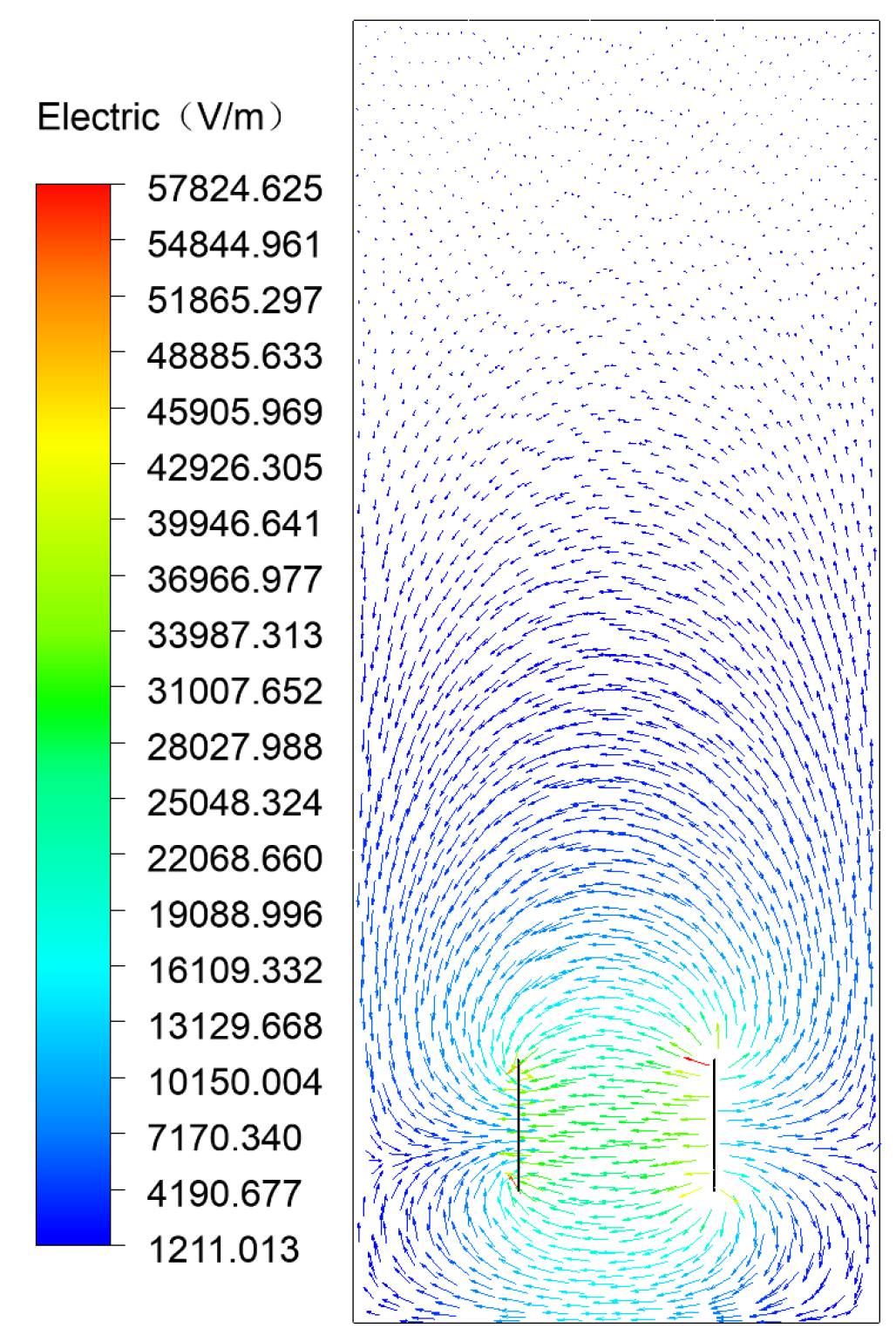
The electric field strength between the electrode plates when the resulting applied AC electric field is not calculated, as shown in Figure 2. Where the applied electric field voltage U = 5 KV, the electrode distance is L = 150 mm, and the length of the electrode plate is 100 mm.

3.3. Gridding and Boundary Conditions

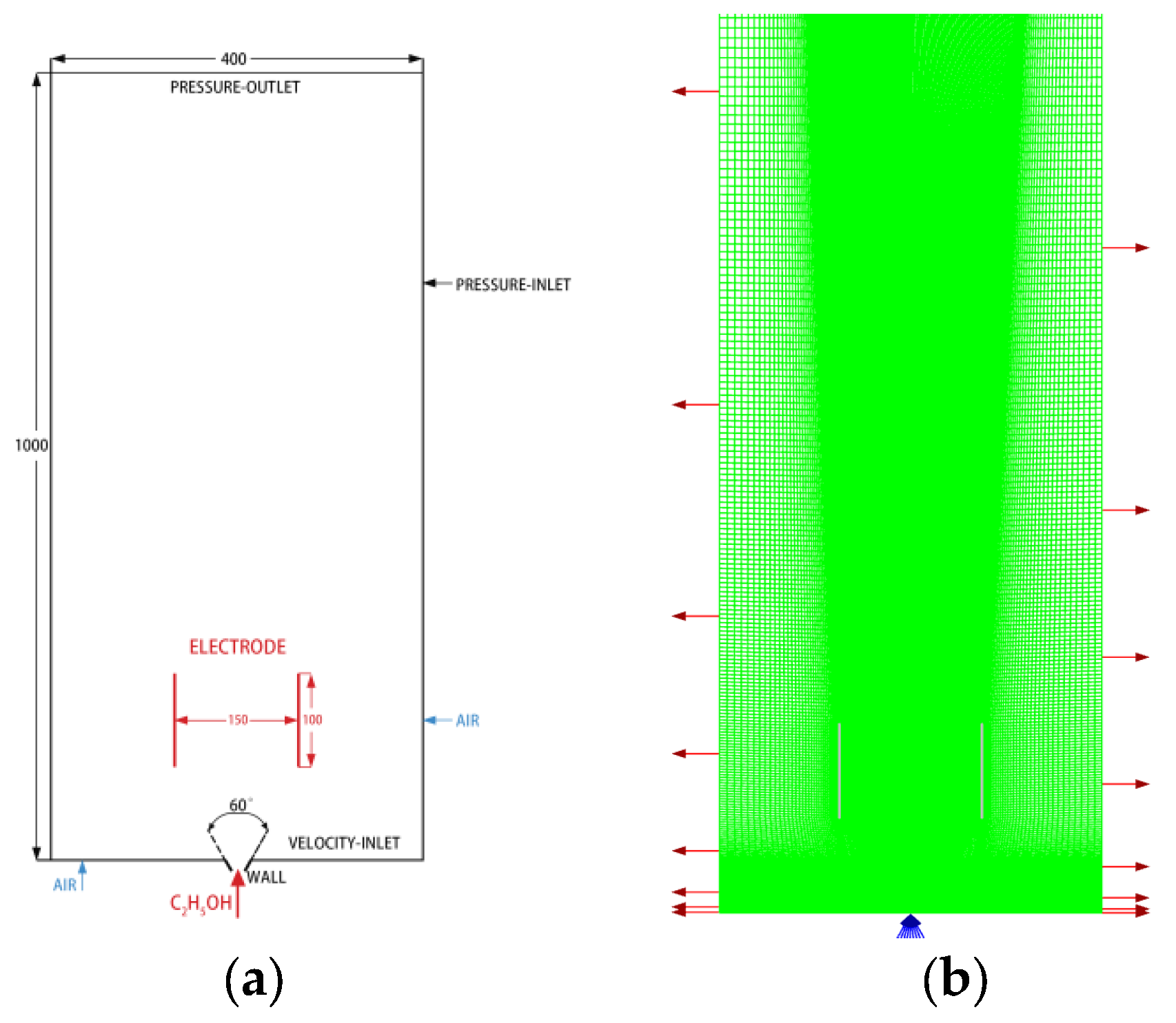
In this paper, the ICEM meshing software is used to mesh the physical model created. Considering the difference between the solid and fluid zones, the calculation area is divided into the solid zone of the atomizer nozzle, the flow, and the combustion zone. The structure of the model is relatively regular in shape, so a map-type grid is used and the grid cell-type format is quad. As shown in Figure 3, the meshing and boundary condition settings for the numerical simulation in this paper are shown.
In this study, three grid quantities, 54,021, 60,610, and 70,800, were set and the change in flame temperature was used to assess grid independence. When the grid number changed from 54,021 to 60,610, the flame temperature changed by 5.4%, and when the grid number changed from 60,610 to 70,800, the flame temperature changed by 1.1%. Therefore, the final choice of meshing with a mesh number of 60,610 gives a more accurate result. To facilitate the detection of changes in characteristic parameters during combustion, monitoring points are established at 0.05 m, 0.10 m, 0.15 m, 0.2 m, and 0.25 m above the burner sub-nozzle, and an isometric detection line is established at 0.2 m above the nozzle with the vertical center line of the jet as the axis of symmetry.
Before the simulation calculation, 15 sets of stable combustion experiments were carried out. The simulation calculation boundary conditions were measured by the experiment: the fuel flow rate is 0.0007 kg/s, and the fuel outlet speed is about 3 m/s, with the standard deviation less than 0.00001 and 0.1, respectively.

3.4. Solution Method

According to the chemical reaction process of ethanol–air diffusion flame, the non-premixed combustion model is selected for the study object, and the numerical simulation is based on the pressure solver with an implicit method to linearize the discrete control equations. The two-dimensional axial plane model is chosen, the absolute velocity is selected for the computational velocity, and the least squares cell is chosen for the gradient of the cell center variable. Pressure and velocity coupling is performed using the coupled algorithm. The finite volume method is used for discretization. The second-order upwind discretization format is used for momentum, energy, and components, and the standard discretization format is used for pressure. The energy residuals were set to 10–6 and the residuals of other parameters were set to 0.001. Based on the setup of the solution method described in this section, the results of the combustion process of the ethanol–air diffusion flame under the conditions of this study were calculated.

4. Numerical Simulation and Analysis of Experimental Results

4.1. Flame Temperature and Velocity

Figure 4 shows a comparison of the experimentally captured visible flame image with the calculated flame temperature profile when no electric field is applied. The results show that the temperature distribution obtained from the simulation is very similar to the flame profile given by the experimentally captured visible image of the flame, numerical simulated temperature distribution changes are close to the experimental measurements. A similar trend can be obtained by comparing the flame luminosity distribution measured by Domenico et al. [29,30] with the temperature flame measured at a point above the equivalent burner.
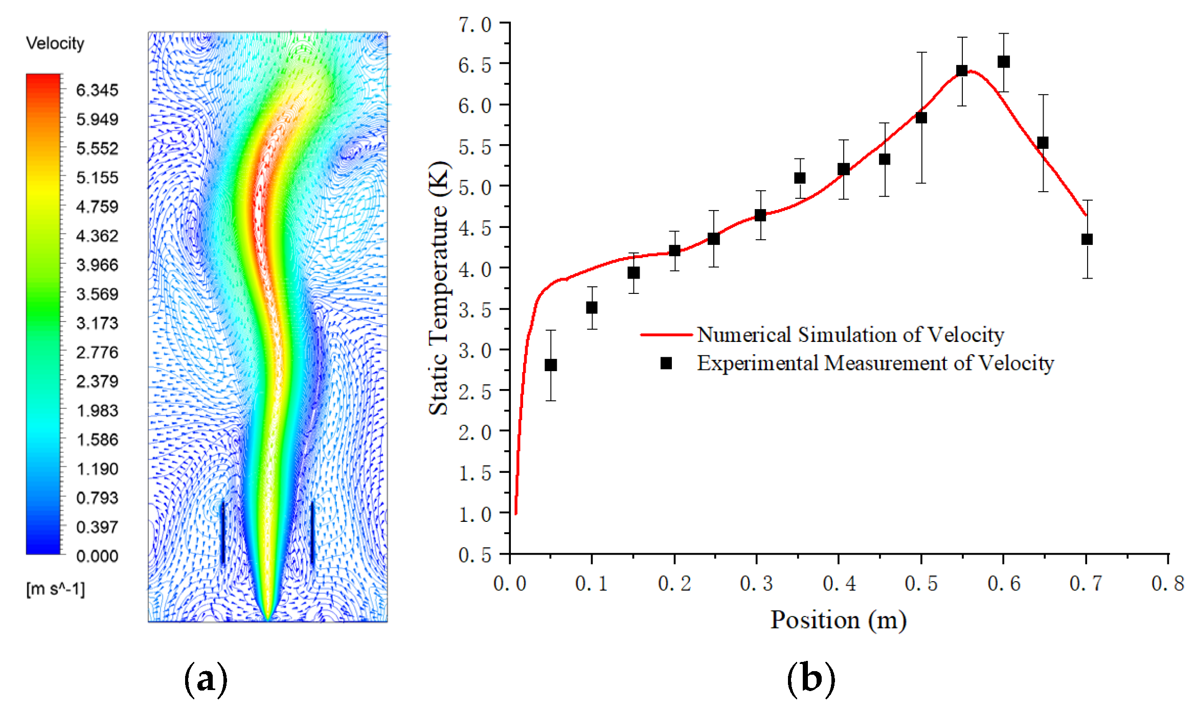
During the experiment, the fluid velocity was measured using an SG313 wind speed probe at 0.05 m intervals directly above the fuel nozzle. Figure 5 shows a cloud plot of the predicted flow field in the ethanol–air flame from this model and a comparison of the predicted fluid velocity in the combustion field with the experimental measurements. The results show that the velocity of the flow field above the burner obtained from the simulation is similar to the experimentally measured velocity and has a similar trend.

4.2. The Electric Field Acts on the Flame to Produce Ionic Wind

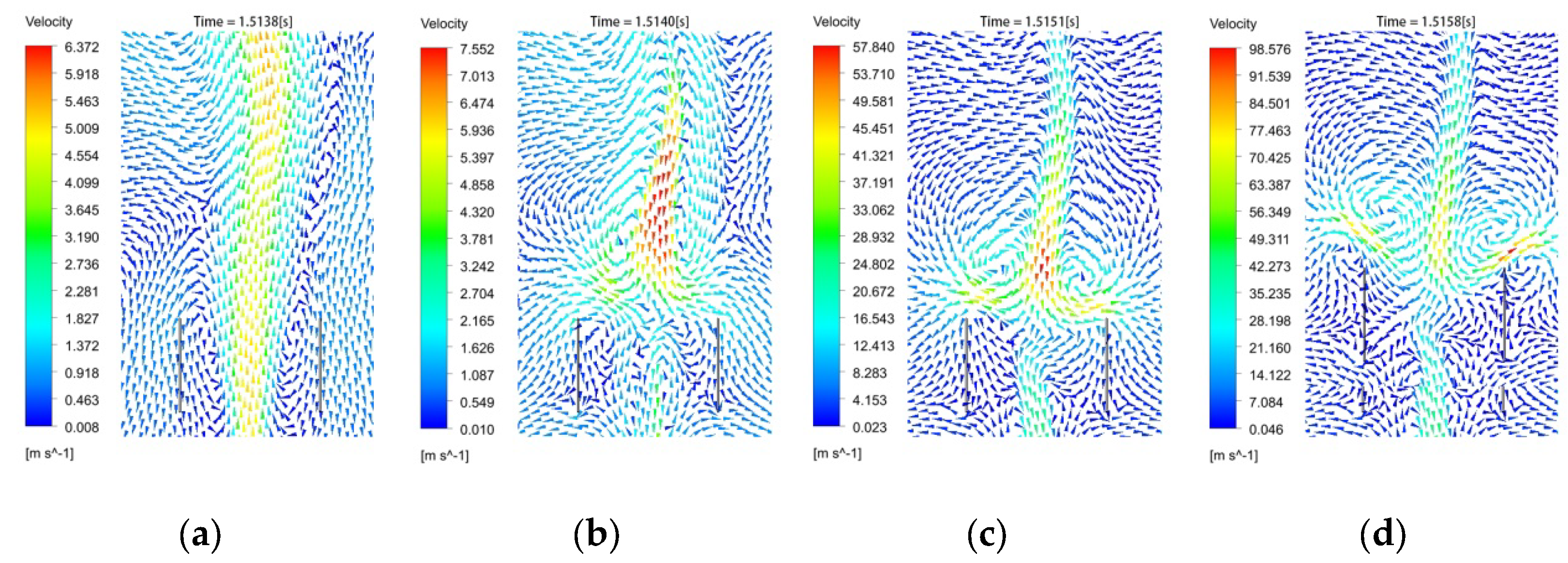
The local magnification of the flow field between the pole plate is shown in Figure 6. Through the observation, it can be seen that between the pole plate, particles are charged by the action of the electric field force. From the original stable combustion state in the vertical upward motion direction, two strands change, respectively, to the nearest pole plate. Additionally, the formation of ion wind in this paper is called the electric field force–ion wind.
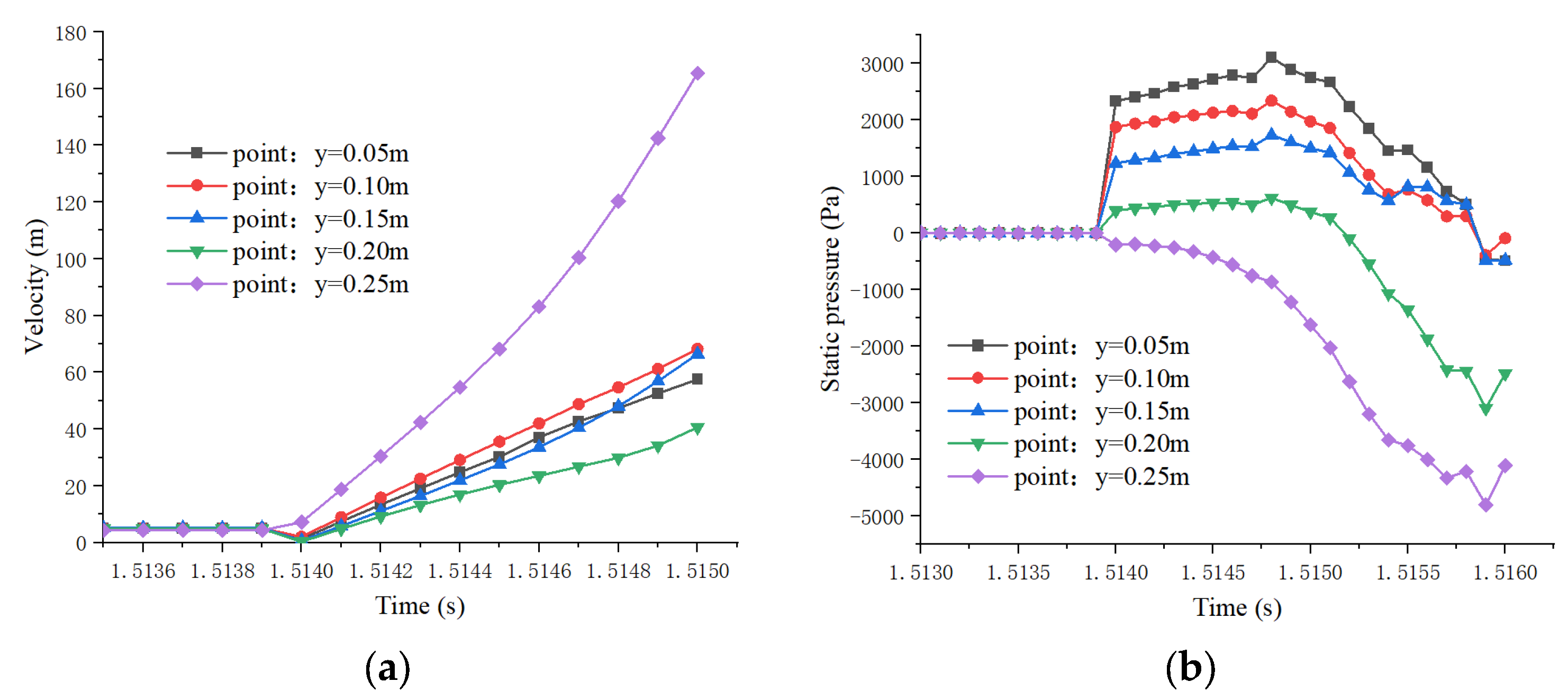
The electric field force–ionic wind affects the flow field between the pole plates. Figure 7a shows the variation of flow velocity with time at points 0.05 m, 0.10 m, 0.15 m, 0.2 m, and 0.25 m above the burner nozzle. It can be seen from the images that the flow velocity at the monitoring points of y = 0.15 and y = 0.20 points between the pole plates is growing under the influence of the transverse electric field force, i.e., the flow velocity between the pole plates is growing.
The Bernoulli integral according to the Euler equation has:
v 2 2 + d p ρ = C
where v is the fluid velocity, p is the pressure per unit volume of fluid, ρ is the density per unit volume of fluid and C is a constant.
From Figure 6 b, it can be seen that as the flow velocity between the pole plates increases, the local low-pressure region rolls up the surrounding fluid and changes the fluid flow velocity and direction in the combustion field. By observation, it can be seen that the appearance of local low pressure further increases the flow velocity between the pole plates. From Figure 2, it can be seen that the electric field intensity between the pole plates is higher than the area outside the plates. The paraelectric effect is known according to the literature [28].
p e = 1 2 ρ v 2 = 1 2 ε E 2 p e + p g = 1 2 ε E 2 + n R T V = C o n s tan t
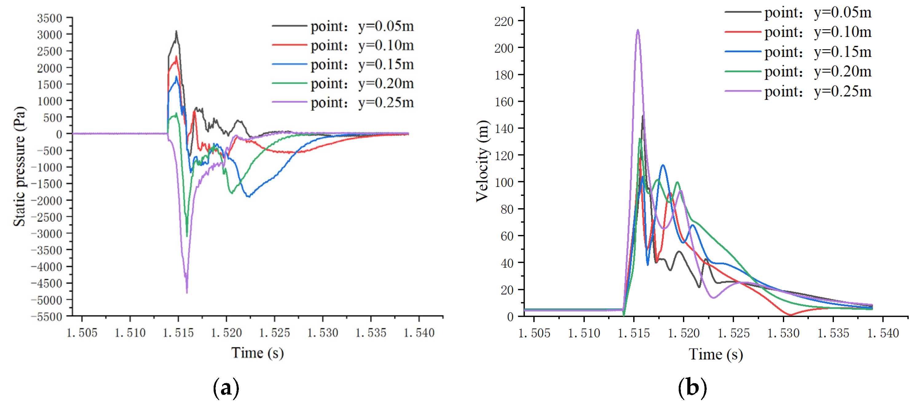
From the above equation, we can know that the electrostatic gradient between the poles is greater than the electrostatic gradient above the poles, then the pressure gradient between the poles is smaller as shown in Figure 8a, the surrounding gas at a higher pressure will flow to this part of the region, so the paraelectric effect. From Figure 8b it can be seen that the charged particles move to the part of high electric field strength, forming a high-speed gas flow.
In summary, the flow field changes in the flame under the action of the transverse electric field can be divided into three stages.
(1)
Electric field accelerated charged particles: In the initial stage of applying transverse AC electric field, charged particles in the combustion region between the pole plates are subjected to electric field force to form directional movement, forming electric field force–ion wind.
(2)
Bernoulli effect to generate local low pressure: in this stage, the electric field force–ion wind increased the local flow velocity of the flow field, according to Bernoulli principle flow velocity increases dynamic pressure rises static pressure decreases, the formation of the local low-pressure region.
(3)
Low-pressure suction formation paraelectric effect–ion wind: Bernoulli effect between the polar plates generated by the local low-pressure region will be formed on the surrounding fluid suction, that is, the air in the combustion region from low voltage gradient to high voltage gradient movement to form paraelectric effect–ion wind as shown in Figure 9, the flame impact.

4.3. Ionic Wind Fire Extinguishing

According to Equation (10), as C, ρ remains constant, the pressure per unit volume of fluid p decreases as the flow rate v within the combustion field increases. A local low-pressure zone is formed at the 0.25 m detection point attachment above the nozzle as shown in Figure 9b. The appearance of the local low pressure resulted in the external fluid being sucked into the low-pressure area and forming a hedge with the rising fluid between the pole plates as shown in Figure 9c,d, the hedge of the fluid also resulted in, a reduction in the velocity of the flow field between the pole plates and a rise in static pressure at the remaining four detection points as shown in Figure 10a when the static pressure at the 0.25 m monitoring point above the burner nozzle continued to fall during the period 1.5139 s–1.5147 s.
As the electric field continues to influence, as shown in Figure 11, by 1.5147 s all five monitoring points show a decreasing trend in static pressure, and by 1.5151 s all five monitoring points are at low pressure, the fluid outside the pole plate is sucked into the low-pressure region of the pole plate. As shown in Figure 11, a large amount of high-velocity fluid enters the combustion region in a short period of time resulting in a sudden drop in temperature between the plates, a decrease in reactant concentration, interruption of the combustion reaction, and flame extinction.

4.4. Experimental and Simulation Analysis

According to the literature [31,32], it is known that the hydrocarbon fuel flame air unaffected by the electric field enters the combustion area from the bottom of the flame or on both sides of the flame, and the charged particles are concentrated in the upper part of the combustion area and the movement area is vertically upward. Because the model uses a two-dimensional plane model for calculation and simulation, the air can only enter the plate into the combustion area from the gap above the plate and between the plate and the bottom of the grid, so the temperature decreases from the top down to below the ignition point in the numerical model.
When the flame is affected by the electric field, the large number of charged particles contained in the flame will produce a directional movement. The movement of the charged particles causes the surrounding air to flow accordingly, and the flow rate in the combustion area is greater than the external flow rate. According to the Bernoulli phenomenon, the pressure between the plates is lower than the external standard atmospheric pressure, and the external air is pressed into the combustion area to form a strong air flow, that is, the isoelectric effect–ionic wind, which affects the material distribution and temperature in the combustion field, as shown in Figure 4, and eventually causes the flame extinguishing. However, during the experiment, the air can enter the flow field from the left and right sides of the plate and above the plate at the same time, so the strong air flow enters the negative pressure area between the plates from both sides of the plate, causing the flame to be extinguished from the bottom up, as shown in Figure 12.
From the macro level, the basic elements of the combustion of ethanol and other liquid combustible materials are: combustible materials, oxide, ignition point, and chain reaction. Any combustion condition needs to meet the above four combustion factors, as long as any element of the four elements can be removed, it can prevent the occurrence of fire or extinguish the fire. The horizontal electric field causes the synergistic effect, ion wind, and low-pressure suction in the combustion area, which affects the temperature and combustible distribution in the combustion area, the temperature is reduced below the ethanol ignition point; ethanol is blown from the plate area, so the plate area does not meet the ethanol combustion conditions, ethanol diffusion flame is extinguished under the influence of the horizontal electric field.
At the micro-level, the time required for fuel combustion consists of two parts: the time ( τ s ) when the fuel is mixed with the air, and the time ( τ c ) when the fuel performs a chemical reaction. The laminar flame theory proposes that all the different flameout phenomena of the laminar flame can be explained by a single standard the number of Damköhler , which is defined as the ratio of the fuel oxidant mixture characteristic time to the chemical characteristic time, i.e.,
D a = τ s / τ c
In the diffusion flame, when D a > 1 the mixing process is slower than the chemical reaction process (the mixing characteristic time is greater than the chemical characteristic time), it is the combustion state; when D a < 1 the mixing process is faster than the chemical reaction process (the mixing holding time is less than the chemical characteristic time), it is the flameout state.
The mixing time of the fuel can be indicated by:
τ s = δ f / u V
In this formula: δ f for the flame thickness, u V for the flow rate of ethanol steam.
Flame thickness can be obtained by the temperature distribution:
δ L = T 2 T 1 max T x
T 1 for the initial fuel temperature, T 1 for the adiabatic flame temperature.
Generally, the reaction time of ethanol vapor oxidation is about 0.002 s [33], and the flame thickness in this study is 3.2 cm. Additionally, the substitution data can calculate a critical flow rate of 16 m/s when the Dunkel number is equal to 1. If the flow rate between the plates is more than 16 m/s, the mixing time of fuel and air during the combustion reaction is less than 0.002 s, D a < 1 is the flameout state, and the combustion reaction is extinguished by the interrupted ethanol diffusion flame.

5. Conclusions

In this paper, the distribution of charged particles in an ethanol–air diffusion flame is simulated using a non-premixed model combined with a previously proposed chemical reaction mechanism for the combustion of ethanol containing charged particles, and the quenching of the ethanol–air diffusion flame by a transverse electric field applied to the combustion region by a compiled UDS is reproduced. The experimental phenomena and simulation results lead to the following conclusions:
  • Using a non-premixed combustion model to simulate the quenching of ethanol–air diffusion flames by a transverse AC electric field between flat plate electrodes, the numerically simulated flame quenching process fits well with the experimental phenomenon and can be used as a basic model for the subsequent research and development of electric field fire extinguishing technology, which is of great significance for electric field driven flame research.
  • The “current-flow-heat” can be divided into three stages: (1) the electric field force; (2) the electric field force–ion wind increases the local flow velocity and the static pressure decreases; (3) the local low-pressure area, namely the air from low voltage gradient to high voltage gradient, which affects the combustion reaction.
  • Through the experimental and numerical simulation analysis, the transverse electric field fire extinguishing mechanism can be summarized as: macroscopic, the combustion area is affected by the paraelectric effect–ion transverse wind temperature reduced below the ethanol ignition point; ethanol is blown away from the plate area by the paraelectric effect–ion lateral wind blowing so that the area between the plates does not meet the combustion conditions of ethanol, and the ethanol diffusion flame is extinguished under the influence of the transverse electric field. Microscopically, the ethanol vapor particles move too fast in the paraelectric effect–ion wind hard combustion reaction, the mixing time of ethanol and air during the combustion reaction is less than 0.002 s, which is not enough to complete the combustion, and the ethanol diffusion flame is extinguished.
The next steps include the development of a 3D simulation model, the use of detailed charged particle chemistry models and laser-induced equipment to monitor component changes during electric fire suppression, and the use of particle image velocimetry to further investigate the mechanism of electric field-driven flame dynamics to support the development of electric field fire suppression technology.

Author Contributions

Conceptualization, B.L. and S.Z.; methodology, S.Z.; software, S.Z.; validation, S.Z., B.Z., T.L. and Q.S.; formal analysis, S.Z.; investigation, S.Z.; resources, S.Z.; data curation, S.Z. and T.L.; writing—original draft preparation, S.Z.; writing—review and editing, B.L.; visualization, B.Z.; supervision, B.L.; project administration, Q.S.; funding acquisition, B.L. and S.Z. All authors have read and agreed to the published version of the manuscript.

Funding

National Key R&D Program Project “Research on the Construction of the Fire Safety Protection System” (2021YFC3100202); National Natural Science Foundation of China Project Law of fire spreading behavior of energized cables and “electric-fluid-heat” Multi-field Synergy (52074202); Graduate Student Innovation Fund “Research on Clean and Efficient Fire Fighting Technology Based on Electric Field Interrupted Chain Reaction” (HGCXJJ2021013).

Institutional Review Board Statement

Not applicable.

Informed Consent Statement

Informed consent was obtained from all subjects involved in the study.

Data Availability Statement

Not applicable.

Conflicts of Interest

The authors declare no conflict of interest.

References

  1. Kuhl, J.; Seeger, T.; Zigan, L.; Will, S.; Leipertz, A. On the effect of ionic wind on structure and temperature of laminar premixed flames influenced by electric fields. Combust. Flame 2017, 176, 391–399. [Google Scholar] [CrossRef]
  2. Kuhl, J.; Jovicic, G.; Zigan, L.; Will, S.; Leipertz, A. Influence of electric fields on premixed laminar flames: Visualization of perturbations and potential for suppression of thermoacoustic oscillations. Proc. Combust. Inst. 2015, 35, 3521–3528. [Google Scholar] [CrossRef]
  3. Kuhl, J.; Jovicic, G.; Zigan, L.; Leipertz, A. Transient electric field response of laminar premixed flames. Proc. Combust. Inst. 2013, 34, 3303–3310. [Google Scholar] [CrossRef]
  4. Lacoste, D.A.; Xiong, Y.; Moeck, J.P.; Chung, S.H.; Roberts, W.L.; Cha, M.S. Transfer functions of laminar premixed flames subjected to forcing by acoustic waves, AC electric fields, and non-thermal plasma discharges. Proc. Combust. Inst. 2017, 36, 4183–4192. [Google Scholar] [CrossRef] [Green Version]
  5. Tinajero, J.; Dunn-Rankin, D. Non-premixed axisymmetric flames driven by ion currentsNon-premixed axisymmetric flames driven by ion currents. Combust. Flame 2019, 199, 365–376. [Google Scholar] [CrossRef]
  6. Cademartiri, L. Taming the flame: Electrical wave blaster could provide new way to extinguish fifires. In Proceedings of the 241st National Meeting and Exposition of the American Chemical Society (ACS), Anaheim, CA, USA, 27–31 March 2011. [Google Scholar]
  7. Mu, S. Electric field cooling and electric field fire suppression. Great Technol. (Sci. Myster.) 2009, 5, 35. [Google Scholar]
  8. Sher, E.; Pinhasi, G.; Pokryvailo, A.; Bar-On, R. Extinction of pool flames by means of a DC electric field. Combust. Flame 1993, 94, 244–252. [Google Scholar] [CrossRef]
  9. Ata, A.; Cowart, J.S.; Vranos, A.; Getegen, B.M. Effects of direct current electric field on the blowoff characteristics of bluff-body stabilized conical premixed flames. Combust. Sci. Technol. 2005, 177, 1291–1304. [Google Scholar] [CrossRef]
  10. Jia, L.; Jinhe, L. Research on the formation of a confined space emergency rescue fire fighting device based on the electric field model. Saf. Sci. Technol. 2018, 13, 54–55. [Google Scholar]
  11. Drews, A.M.; Cademartiri, L.; Whitesides, G.M.; Bishop, K.J.M. Electric winds driven by time oscillating corona discharges. J. Appl. Phys. 2013, 114, 143302. [Google Scholar] [CrossRef] [Green Version]
  12. Drews, A.M.; Cademartiri, L.; Chemama, M.L.; Brenner, M.P.; Whitesides, G.M.; Bishop, K.J.M. AC electric fields drive steady flows in flames. Phys. Rev. E Stat. Nonlin. Soft Matter Phys. 2012, 86, 036314. [Google Scholar] [CrossRef] [Green Version]
  13. Belhi, M.; Domingo, P.; Vervisch, P. Modelling of the effect of DC and AC electric fields on the stability of a lifted diffusion methaneair flame. Combust. Theory Model. 2013, 17, 749–787. [Google Scholar] [CrossRef]
  14. Belhi, M.; Lee, B.J.; Bisetti, F.; Im, H.G. A computational study of the effects of DC electric fields on non-premixed counterflow methane-air flames. J. Phys. D Appl. Phys. 2017, 50, 494005. [Google Scholar] [CrossRef] [Green Version]
  15. Belhi, M.; Lee, B.J.; Cha, M.S.; Im, H.G. Three-dimensional simulation of ionic wind in a laminar premixed Bunsen flame subjected to a transverse DC electric field. Combust. Flame 2019, 202, 90–106. [Google Scholar] [CrossRef]
  16. Lopez-Camara, C.F.; Belhi, M.; Im, H.G.; Dunn-Rankin, D. Numerical Simulations of Laminar Nonpremixed CH4-Air Jet Flames Influenced by Varying Electric Fields. In Proceedings of the 11th U.S. National Combustion Meeting, Pasadena, CA, CA, USA, 24–27 March 2019. [Google Scholar]
  17. Gan, Y.; Wang, M.; Luo, Y.; Chen, X.; Xu, J. Effects of direct-current electric fields on flame shape and combustion characteristics of ethanol in small scale. Adv. Mech. Eng. 2016, 8, 1687814015624846. [Google Scholar] [CrossRef] [Green Version]
  18. Luo, Y.; Gan, Y.; Jiang, Z. An improved reaction mechanism for predicting the charged species in ethanol-air flame. Fuel 2018, 228, 74–80. [Google Scholar] [CrossRef]
  19. Luo, Y.; Jiang, Z.; Gan, Y.; Liang, J.; Ao, W. Evaporation and combustion characteristics of an ethanol fuel droplet in a DC electric field. J. Energy Inst. 2021, 98, 216–222. [Google Scholar] [CrossRef]
  20. Luo, Y.; Gan, Y.; Xu, J.; Yan, Y.; Shi, Y. Effects of electric field intensity and frequency of AC electric field on the small-scale ethanol diffusion flame behaviors. Appl. Therm. Eng. 2017, 115, 1330–1336. [Google Scholar] [CrossRef]
  21. Renzo, M.D.; Pascazio, G.; Urzay, J. The breakdown of self-similarity in electrified counterflow diffusion flames. Combust. Flame 2019, 205, 231–240. [Google Scholar] [CrossRef] [Green Version]
  22. Renzo, M.D.; Palma, P.; Marco Donato, T.; Giuseppe, P.; Javier, U. The effects of incident electric fields on counterflow diffusion flames. In Proceedings of the 70th Annual Meeting of the APS Division of Fluid Dynamics, Denver, CO, USA, 19–21 November 2017. [Google Scholar]
  23. Sayed-Kassem, A.; Gillon, P.; Idir, M.; Gilard, V. Numerical simulation of the effect of a DC electric field on a laminar ethylene diffusion flame. Combust. Sci. Technol. 2019, 1–12. [Google Scholar]
  24. Sayed-Kassem, A.; Elorf, A.; Gillon, P.; Idir, M.; Sarh, B.; Gilard, V. Numerical modelling to study the effect of DC electric field on a laminar ethylene diffusion flame. Int. Commun. Heat Mass Transf. 2021, 122, 105167. [Google Scholar] [CrossRef]
  25. Wei, C.; Junyu, Y.; Yihua, R.; Li, S.-Q. Numerical Study About the Ions Effect to the Combustion Reaction Rate Under the Eclectic Field. J. Eng. Thermophys. 2018, 39, 1395–1400. [Google Scholar]
  26. Limin, Y. Experimental Study and Simulation Analysis of Electric Field and Small-Scale Flame Interaction; Beijing Jiaotong University: Beijing, China, 2012. [Google Scholar]
  27. Renzo, M.D.; Pascazio, G. A mixture fraction space model for counterflow diffusion flames with incident electric field. Combust. Flame 2020, 218, 260–275. [Google Scholar] [CrossRef]
  28. Roth, J.R. Aerodynamic flow acceleration using paraelectric and peristaltic electrohydrodynamic effects of a One Atmosphere Uniform Glow Discharge Plasma. Phys. Plasmas 2003, 10, 2117–2126. [Google Scholar] [CrossRef]
  29. De Domenico, F.; Guiberti, T.F.; Hochgreb, S.; Roberts, W.L.; Magnotti, G. Temperature and water measurements in flames using 1064 nm Laser-Induced Grating Spectroscopy (LIGS). Combust. Flame 2019, 205, 336–344. [Google Scholar] [CrossRef]
  30. Yang, H.; Feng, Y.; Wang, X.; Jiang, L.; Zhao, D.; Hayashi, N.; Yamashita, H. OH-PLIF investigation of wall effects on the flame quenching in a slit burner. Proc. Combust. Inst. 2013, 34, 3379–3386. [Google Scholar] [CrossRef]
  31. Yan, Y.; Huang, W.; Tang, W.; Zhang, L.; Li, L.; Ran, J.; Yang, Z. Numerical study on catalytic combustion and extinction characteristics of pre-mixed methane-air in micro flatbed channel under different parameters of operation and wall. Fuel 2016, 180, 659–667. [Google Scholar] [CrossRef]
  32. Niu, J.; Ran, J.; Li, L.; Du, X.; Wang, R.; Ran, M. Effects of trapezoidal bluff bodies on blow out limit of methaneair combustion in a micro-channel. Appl. Therm. Eng. 2016, 95, 454–461. [Google Scholar] [CrossRef]
  33. Gan, Y.; Wang, M.; Shi, Y. Combustion Temperature and Stability Characteristics of Ethanol Small-scale Jet Diffusion Flame. Proc. CSEE 2014, 34, 2802–2807. [Google Scholar]
Figure 1. Experimental platform.
Fire 05 00196 g001
Figure 2. Electric field intensity of AC electric field.
Fire 05 00196 g002
Figure 3. Two-dimensional physical model of combustion system. (a) Schematic diagram of a two-dimensional physical model; (b) grid division.
Fire 05 00196 g003
Figure 4. Contour of flame temperature and flame image in the experiment without electric field. (a) Flame temperature clouds; (b) experimental flame image; (c) comparison of simulated temperature distribution with experimentally measured temperature.
Fire 05 00196 g004
Figure 5. Prediction of flow velocity in combustion zone and experimental measurement data. (a) Flow field velocity vector diagram; (b) comparison of predicted flow rates with experimental measurement data.
Fire 05 00196 g005
Figure 6. Schematic diagram of flow field vector variation (ad).
Fire 05 00196 g006
Figure 7. (a) Initial application of electric field variation of static pressure with time at points 0.05 m, 0.10 m, 0.15 m, 0.2 m, 0.25 m above the burner nozzle; (b) initial application of electric field variation of flow velocity with time at points 0.05 m, 0.10 m, 0.15 m, 0.2 m, 0.25 m above the burner nozzle.
Fire 05 00196 g007
Figure 8. (a) Variation of static pressure with time at points 0.05 m, 0.10 m, 0.15 m, 0.2 m, 0.25 m above the burner nozzle; (b) variation of velocity with time at points 0.05 m, 0.10 m, 0.15 m, 0.2 m, 0.25 m above the burner nozzle.
Fire 05 00196 g008
Figure 9. Flame by the lateral effect of the formation of paraelectric effect–ion wind (ae).
Fire 05 00196 g009
Figure 10. Numerical simulation of the change in temperature distribution of fire extinguishing by transverse AC electric field.
Fire 05 00196 g010
Figure 11. (a) Temperature change over time at each monitoring point; (b) ethanol concentration change over time at each monitoring point.
Fire 05 00196 g011
Figure 12. Flame luminosity changes in the transverse AC electric field experiment.
Fire 05 00196 g012
Table 1. Thermophysical properties of 298 K ethanol.
PurityDensity/g·cm−3Viscosity/mPa·sSpecific Heat
Capacity/J·g−1·K−1
Electrical Conductivity/10−7 S·m−1Surface Tension/10−3 N·m
>99.7%0.7981.162.581.3522.8
Publisher’s Note: MDPI stays neutral with regard to jurisdictional claims in published maps and institutional affiliations.