Abstract
In recent years, glass has been a largely used material for load-bearing or non-structural components in buildings and constructions. For this reason, dedicated calculation methods and approaches are required for the major loading and boundary conditions that are of technical interest for safe design purposes. Among others, the resistance and mechanical performance of glass elements under fire exposure still represents an open challenge. This paper elaborates on the failure detection methods for out-of-plane loaded glass panels that are subjected to fire loading and simultaneous mechanical loads. As known, the conventional method for thermal failure detection is based on the maximum temperature gradient in glass, and its comparison with a set of allowable standardized values. However, especially for ordinary glass components in buildings that are required to sustain combined mechanical loads, the overall structural performance is even more complex to predict. This design issue is given to a combination of pure mechanical aspects (i.e., sustained loads and corresponding stress–strain analysis) and thermo-physical phenomena, that depend on the progressive modification of material properties while increasing temperatures. This research study, accordingly, investigates the sensitivity of input parameters on the failure time of a given glass element under fire and sustained mechanical loads. A major advantage is taken from finite element (FE) numerical analyses and standardized failure detection methods of literature, that are selected for comparative purposes. Further, the paper also introduces the “stress approach” that can be used to quantify (in place of the conventional thermal gradient) the actual effects of assigned thermal exposure and mechanical loads.
1. Introduction
In recent years, ordinary soda-lime silica glass is increasingly being used in buildings not only as secondary infill of structural frames but also as a load-bearing material for building components like floors, roofs, walls, and columns that can be subjected to a multitude of permanent/accidental mechanical loads and combinations. In this regard, extended recommendations for structural design are in continuous development and elaboration [1,2]. In spite of a large number of practical applications and research projects on structural glass, relatively little is recognized about its mechanical performance under fire scenarios as a constructional material. As far as accidental design actions may derive from natural hazards, such a condition represents a huge limitation for design developments. Furthermore, wildfires represent a high risk in the same way as tornados, hurricanes and earthquakes. Examples of load-bearing analyses for glass systems in fire conditions are reported in [3,4,5,6] for selected configurations, including experimental and numerical studies. However, efforts are still required to develop standardized recommendations in support of safe structural analysis and design.
On one side, ordinary glass finds novel applications in buildings, and major uncertainties on the structural/material side can be represented by the lack of design tools to cover all the possible load/boundary conditions or combinations with different materials. At the same time, fire engineering research is also taking advantage of the application of innovative methods and techniques that can be used to describe real fire accidents [7]. At the wildland–urban level, the current risk is found in fire that may spread through both wildland and community and threaten the natural environment, included glass-based building enclosures and components [8,9]. Static and dynamic wildfire models based on statistical analyses are also of support of fire engineering developments [10].
It is worth noting, in this regard, that a large amount of research efforts reported in the literature is already available for ordinary glass in fire conditions. However, most of those studies are focused on the investigation (experimental, analytical, or numerical) of the fire performance (failure time and “fallout” collapse mechanism) of secondary, cladding elements for doors, windows, and facades [11,12,13,14]. The thermal breakage description and its realistic prediction are known to be highly affected by the variability of material properties. Boundary conditions and compartment fire dynamics can also strongly modify the temperature distribution and evolution in glass (Figure 1a and [15]), thus resulting in possible severe variations for the expected failure time. Besides, efficient numerical tools validated to experiments can be developed in support of design (Figure 1b and [16,17]).
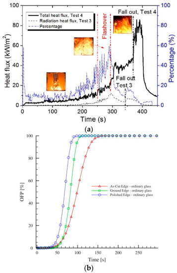
Figure 1.
Analysis of thermal breakage in glass cladding: (a) experimental analysis of boundary effects (reproduced from [15] with permission from Elsevier, license number 4996960474361, January 2021) and (b) finite element numerical prediction of the probability failure for ordinary glass under radiant heating, as a function of edge finishing (reproduced from [17] with permission from Elsevier, license number 4996960742227, January 2021).
The major (and joint) limit of those applications is that the selected vertical elements are tested in fire conditions without (self-weight excluded) other “sustained mechanical loads”. Such a definition is used in this paper to describe a dead load that is kept constant during the overall fire exposure, and thus affects further the overall mechanical performance of the elements to verify. This operational condition is typical of horizontal building components in roofs or slabs (i.e., Figure 2) that are already designed with ordinary glass, but could be even subjected to a thermo-mechanical combination of actions. In this regard, few literature studies can be found about the mechanical behaviour and load-bearing capacity of structural glass components under combined fire and sustained out-of-plane loading [3,18,19]. This paper explores further the reliability of the available failure detection methods that are expected to support the required verifications, towards the definition of standardized procedures.
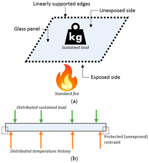
Figure 2.
Reference system: (a) schematic setup and (b) cross-section.
2. Problem Formulation
For the purpose of this research study, let us refer to the system in Figure 2. Once a load-bearing element composed of glass is subjected to sustained mechanical loads but also fire exposure, the overall performance of the element (and especially the prediction of its actual failure condition) is a well-known complex phenomenon to describe.
For a general constructional member composed of traditional materials, the conventional approach for the evaluation of the expected fire resistance follows in fact some basic steps that include:
- the selection of the relevant design fire scenarios and the determination of the corresponding design fires;
- the determination of the reference time–temperature curve;
- and the calculation of temperature evolution within the structural member to verify, as well as the analysis of, the mechanical behaviour of the structure exposed to fire.
Finite element (FE) numerical models, although challenging, can be efficiently used for predicting the fire resistance of load-bearing members composed of timber, steel, concrete (see for example [20] and Figure 3 for wooden structures).
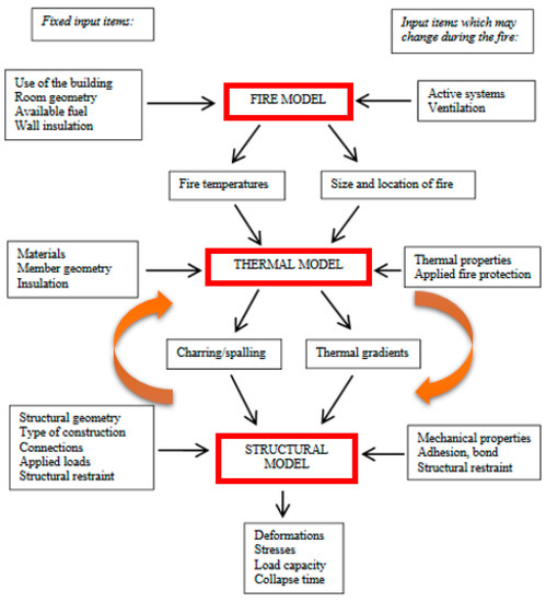
Figure 3.
Adaptation to glass structures of the conventional flow chart for the fire resistance assessment of structural members made of timber (from [20]).
For traditional load-bearing constructional members, the fire endurance is usually checked and certified experimentally in terms of deflection and deflection rate parameters (in-plane or out-of-plane) under standard fire exposure, and their comparison with conventional limits. The EN 1363-1:2012 [21], in this regard, provides specific limit values for walls or single members with ideal mechanical restraints that can be efficiently used for conventional load-bearing systems. This “deflection criterion” results from past attempts of providing a standardized approach to assess the collapse or utilization of a given structure. A given deflection or deflection rate is hence expected to support the assessment of incipient failure or residual capacity. However, the approach has well-known limits of interpretation and generalization [22]. Further, it is proved by several studies that the standardized limit values hardly apply to structural members characterized by unconventional boundaries, or setup, or materials (see for example [23]). The basic principle of this approach, moreover, is that increasing the imposed sustained loads (and this amplitude should be representative of the practical loading condition for the system/member to verify), the overall fire endurance decreases. This outcomes results from a simple combination of fire exposure effects (with mechanical degradation of materials, etc.) with the superimposed mechanical loads (and increasing deformations).
Given the sensitivity of thermal phenomena summarized in Section 1, it is rationally expected that the failure analysis of a given glass panel under combined thermal exposure and mechanical loads would be represented by the combination of the two stress fields. On the other side, the actual issues for the numerical-aided fire resistance assessment are indeed related to:
- quantification of overall load-bearing effects due to temperature dependent (TD) material properties, in place of temperature independent (TI) input parameters;
- quantification of thermal exposure vs. mechanical load effects (i.e., superimposed stress peaks) on a given glass panel variably restrained (with TD or TI material properties);
- and thus on the accuracy and efficiency of the existing calculation methods, and their applicability to structural glass elements that are expected to sustain a set of design mechanical loads.
In this paper, a detailed analysis is thus presented for square monolithic glass panels, with 5 mm in thickness, that are subjected to fire exposure and different amplitudes of sustained mechanical loads (Figure 2). With the support of original FE numerical models developed in ABAQUS [24] and validated to past studies, the sensitivity of selected failure detection strategies of literature is investigated. Discussion is thus presented for a selection of loading configurations. In doing so, major advantage is taken especially from [4], where the out-of-plane bending response of monolithic float glass elements in fire with sustained loads has been investigated with experiments and numerical models. Besides, given that the experimental setup in [4] was affected by the presence of unprotected steel restraints for glass, the current investigation is primarily focused on linearly supported elements with edge restraints that do not suffer from direct fire exposure (as it is typical of load-bearing structural glass applications, see for example [19]). Furthermore, a future extension of the results discussed herein should necessarily include also laminated glass elements composed by two or more bonded layers of glass.
3. Material Properties of Glass
The issue of failure analysis and detection for generally loaded and restrained glass panels is strictly related to the basic material properties (Figure 4). As far as a simple monolithic glass element is taken into account, the analysis is relatively “easy” and does not need to account for the actual characterization of bonding interlayers or boundaries. Otherwise, specific attention could be in any case required for “nonideal” restraints and supports, as well as for resisting sections of glass members that can be used as load-bearing elements in constructions.
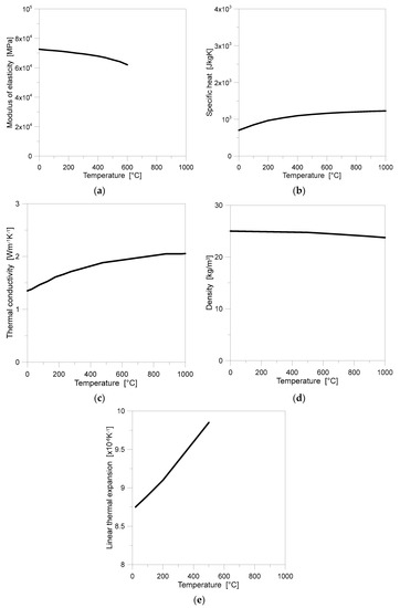
Figure 4.
Selected glass material properties, with evidence of their sensitivity to temperature variations: (a) modulus of elasticity; (b) specific heat; (c) thermal conductivity; (d) density; (e) thermal expansion coefficient.
In this context, several studies report on the experimental analysis of thermo-physical (and some mechanical) properties of glass under elevated temperature [25,26,27,28,29]. A still open question, however, is certainly related to the actual resistance of glass under high temperature. Despite the fact that strength is a critical parameter for glass, it is the least well known among other parameters, such as thermal properties, which have been extensively studied before [12]. The disproportional scope of tests regarding the thermal and mechanical properties is related to complexity of test execution of the latter. This particularly applies for the properties of glass at elevated temperature. The degradation of stiffness and strength properties of glass is caused by accelerated corrosion that is present with rising temperature [28].
Tensile strength of glass has been studied extensively at room temperature, however, information about variation of this parameter with temperature is very limited and in many cases the results they are in contradiction with each other [12]. Stanworth [29] reports the effects of temperature on the strength of sheet-glass samples. The strength decreases slightly up to 200 °C, then increases again up to 400 °C. It should be noted the values of glass strength are relatively high, which is due to the fact that the edges of glass samples were fire-finished before testing. Xie et al. [14] performed tensile tests on dog-bone shape specimens in a room temperature (25 °C) and hot environment (200 °C). It was found that at the same temperature the critical breakage stress is highly dependent on the specimen thickness. Moreover, the critical breakage stresses of 6, 8, 10, and 12 mm thick float glass are, respectively, 7%, 48%, 16%, and 19% lower in a hot environment than at room temperature for each thickness. This accounts for an average of 13.5% loss of tensile strength at the temperature of 200 °C compared to the results at room temperature. Minko et al. [27] report that glass strength decreases by 25% when heated up to 100 °C.
Further exposure at 520 °C for a 10 h period decreases the strength by 35%. The authors explain the phenomena by desorbing moisture entrapped in the capillaries within the outer (gel) layer of glass. Li et al. [26] investigated the bending fracture strength of glass in three-point bending at different temperatures ranging from a room temperature (20 °C) to 650 °C with two types of specimens: one with artificial scratch and the other intact. The results show that the bending strength of specimens without surface scratch initially increases to its peak value of 124 MPa at around 250 °C and then decreases to the value of 51 MPa at 600 °C. The bending strength of the specimens with surface scratch is rather stable, in the considered temperature range the average value is 20 MPa.
Studies reported in [12,14,26,28,29] proved experimentally that the tensile bending resistance of glass shows high sensitivity to temperature. The variations of modulus of elasticity, thermal conductivity, specific heat, density, and linear thermal expansion coefficient as a function of temperature are given in Figure 4 [3,26,30,31]. Regarding the modulus of elasticity, its value decreases significantly for temperatures above 600 °C, and thus certainly represents an influencing parameter for design.
4. Reference Approaches for Thermal Failure Detection
One of the main issues when evaluating the fire-resistance of glass components is related to the thermal failure detection. In literature, several approaches were proposed. This includes simplified methods that assume glass strength at room temperature and commonly neglect temperature-dependent material properties of glass that could affect the failure time under fire exposure.
4.1. Simplified Design Procedure of Standards
A simplified approach to detect thermal failure in a glass pane subjected to temperature load was given in a preliminary European standard [32]. It specifies allowable temperature gradient for monolithic glass depending on the edge condition (see Table 1).

Table 1.
Allowable temperature gradients for monolithic float glass, according to prEN thstr:2004 provisions [32].
4.2. Refined Analytical Modeling
Foraboschi [33] presented an analytical model to study the “thermally induced stresses” (or for simplicity, “thermal stresses”) in square glass elements that are subjected to a given thermal scenario. The cited approach is thus presented as suitable to calculate separately the thermal stresses for a general element, that must be then superimposed to mechanical stresses due to additional loads. The study points out the importance of thermal stress assessment especially for annealed glass, both with and without additional mechanical stresses. Moreover, with the support of analytical discussion, the study shows that empirical formulas of literature (linear models) are radically inaccurate, and thus drastically over-conservative.
The study in [33] represents an improved model that can support designers and practitioners since it provides a more detailed analysis of thermal induced stresses for general glass panels. The schematic model is based on Figure 5, where the edge effects due to radial thermal exposure are shown for a square panel.
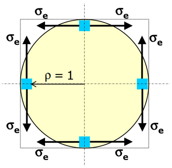
Figure 5.
Schematic representation of circumferential (hoop) stress at the edges of a glass panel under radiant thermal loading, with evidence of tensile stress at the edge which may cause thermal crack (blue dots). Figure reproduced from [33] with permission from Elsevier, license number 4996990464010, January 2021.
The stress edge σe due to temperature variations agreeing with Figure 5 is given by the sum of N stress components associated to N temperature terms. Each i-th stress term is generally defined in [33] as:
where all the known input parameters are representative of material (E, α), while the N = 2 parameters are given for thermal loading (Timax, λi) and edge temperature Tie, that is again a function of Timax and λi.
The final result is thus given by:
4.3. Simplified Numerical Tools
Over time, a number of simplified numerical tools have been developed in support of designers.
BREAK1 (Berkeley Algorithm for Breaking Window Glass in a Compartment Fire) is a program which calculates the temperature history of a glass window exposed to user described fire conditions [34]. The calculations are stopped when the glass breaks. The inputs required are the glass thermal conductivity, thermal diffusivity, absorption length, breaking stress, Young’s modulus, thermal coefficient of linear expansion, thickness, emissivity, shading thickness, half-width of window, the ambient temperature, numerical parameters and the time histories of flame radiation from the fire, hot layer temperature and emissivity, and heat transfer coefficients. The outputs are temperature history of the glass normal to the glass surface, and the window breakage time.
The basic assumption is that the difference between the integrated bulk temperature is over the central pane and the coldest temperature on the pane edge which produces the strain that leads to cracking. Under this assumption, the governing criterion for glass breakage is:
where ∆Tb is the difference between the bulk (average) temperature over the central pane and the coldest temperature on the pane edge, σb is the glass strength, E is the Young’s modulus of glass, β is the thermal coefficient of linear expansion. The right part of the equation proposed by Emmons [25] is further multiplied by a factor to account for compressive effects of the shaded region.
Moreover, for comparative purposes, the same glass panel was also analyzed with the support of BREAK1 software. To this aim, the following input parameters were taken into account for the material characterization:
- density 25 kN/m3,
- conductivity 1.06 W/(mK),
- expansion 8.3e−6 1/K,
- specific heat 870 J/(kgK),
- emissivity 0.950 [-]
- heat transfer coefficient (exposed side) 25 W/m2K
- heat transfer coefficient (unexposed side) 8.02 W/m2K
The above assumptions can thus support efficient calculations for glass panels under thermal exposure. Following [33], however, the so-collected numerical predictions are expected in severely approximated values, on the conservative side.
EASY software is an alternative option presented by Wang et al. [12] to efficiently predict the breakage time of glass panels under fire, with the inclusion of various shading systems and configurations.
5. Finite Element Numerical Investigation
The alternative approach to detect the failure of glass under fire exposure is to investigate numerically. In this manner, the approach is not limited by assumption of the existing software such as boundary conditions, loading scheme, geometrical details, and constant material properties of glass.
5.1. General Setup
As a case study, one 1 × 1 m2 monolithic glass panel with 5 mm in thickness is considered. The panel is subjected to fire (Section 5.2) and a distributed sustained load q (Section 5.3). Separate and cumulative action of thermal and mechanical loads is thus considered. The panel is simply supported along all edges by 10 mm thick × 50 mm wide pads made of semirigid material. This set-up represents a typical boundary condition for a horizontal glass element with linearly restrained edges. To investigate the temperature and stress histories a critical section at the edge of the panel is selected (see Figure 6).
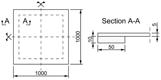
Figure 6.
Studied monolithic glass panel: front view and cross-sectional detail in the region of supports (dimensions in mm).
5.2. Thermal Load
A standard temperature loading from ISO 834-1 [35] was applied to the reference glass panel. The typical trend shown in Figure 7 was described in ABAQUS (Section 5.5) and assigned—through the whole step time—to a uniform surface of glass (bottom face in Figure 6, with the exclusion of the region of edge restraints). In other words, possible variations in the exposed surface of glass (as a direct effect of progressive out-of-plane bending deformations and sliding of the pane at the edges) were disregarded.
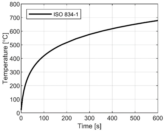
Figure 7.
Standard time–temperature curve according to ISO 834-1.
5.3. Sustained Load
There are no doubts for the mechanical analysis of variably loaded and restrained glass panels, given that the maximum tensile stress peak must be limited and compared to the material resistance in cold conditions.
In the FE models subjected to additional sustained mechanical load (in combination to the fire exposure), a uniform pressure with constant amplitude q (but different magnitude, for a selection of loading scenarios) was applied to the top surface of glass, and kept fixed through the whole fire exposure. For this purpose, the “failure pressure” qR,0 responsible of the first crack/tensile stress peak in the glass panel in out-of-plane bending, at room temperature, was first estimated. The mechanical load in use reflects a typical situation where a glass floor panel may be required to carry on a vertical (downwards) load and a fire occurs from below (bottom surface exposed).
Later on, the FE parametric study was carried out on the same glass panel under the assigned fire temperature in time and a given ratio of mechanical load, compared to the qR,0 value (Table 2). From all the implemented FE models, stress and temperature distribution and evolution in time was collected in the solid elements and mesh nodes.

Table 2.
Selected sustained load configurations for the examined glass panel.
5.4. Approaches for Detection of Failure Time
To detect the failure time for the pane subjected to separate and cumulative action of thermal and mechanical loads, two approached are defined:
- “Temperature approach” (“TEMP”, in the following)—the failure time is derived based on the difference between the bulk (average) temperature over the central pane and the coldest temperature on the pane edge;
- “Stress approach” (“STRESS”, in the following)—the failure time is derived based on the resulting stress field and comparison of extreme values of maximum principal stress compared to the allowable stress.
The herein called “STRESS” approach is taken into account in this study, and applied to glass panels under combined thermal exposure with sustained mechanical loading.
5.5. Finite Element Numerical Investigation
A 3D numerical model of a 1 × 1 m2 glass pane (5 mm in thickness) was created using the commercial software ABAQUS/Standard. The pane was simply supported along all edges on elastic pads with Ep = 10 MPa and Poisson’s ratio of 0.45. Between the glass pane and the edge pads, a surface-to-surface contact interaction allowing for edge lifting and relative sliding (with a static friction coefficient of 0.5) but preserving possible compenetration in compression was also assumed. To minimize the number of finite elements and increase the computational efficiency of the simulations, only a quarter of the pane with appropriate symmetry restraints was modelled (Figure 8).
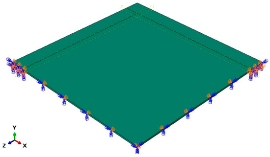
Figure 8.
General view (1/4th the nominal geometry) of the reference FE numerical model (ABAQUS/Standard).
Since the main aim of the study was to determine simultaneously the temperature and stress fields, a fully coupled thermal–stress analysis was used. All components were modelled with a set of 3D continuum elements consisting of 8-node, coupled displacement-temperature solid bricks with full integration (C3D8T type from ABAQUS element library). Following a convergence study aimed at the verification of the mesh quality, a regular mesh was used for these brick elements, with an edge length of 25 mm. For the glass pane and the pads, five and three solid elements were also defined in the thickness of each component (Figure 9). In the typical FE model, both TI and TD material properties of glass, such as Young’s modulus, conductivity, and specific heat, were taken from literature references (see Figure 4). At this stage of the study, moreover, glass material was described with a linear elastic constitutive law, deprived of any strength limit in tension or compression. To this aim, the stress evolution in the whole glass panel was continuously monitored through each simulation, at selected control points representative of critical regions for the examined setup.
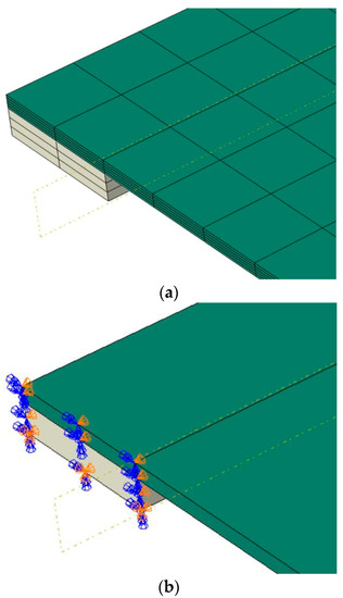
Figure 9.
FE numerical model (ABAQUS/Standard): (a) assembly detail at the edges (hidden mesh) and (b) restraints.
The fully coupled thermal–stress analysis was composed of two stages. In the first stage (with a total step time of 1 s), a mechanical load of different amplitude was applied on the top surface of glass, and kept constant. In the second stage, the same glass pane was subjected to an additional temperature distribution. The total step time for the second stage was set to 600 s of fire exposure/out-of-plane bending analysis.
In doing so, the heat transfer boundary conditions (i.e., radiation and convection) were defined as incident radiation from a black-body, with the temperature according to the ISO 834 standard. In case of the fire exposed (bottom) surface of glass, the corresponding heat transfer coefficient was set to 25 W/m2K. Regarding all unexposed surfaces (top face and region of edges), the conventional heat transfer coefficient of 8.02 W/m2K was used. A standard emissivity value of 0.95 was finally used for glass. In the case of the supporting pads, no thermal sensitivity was taken into account, as a major effect of the explored boundary condition (protected supports).
In the simulations, moreover, additional physical constants were also taken into account, such as the Stefan–Boltzmann constant (5.67 × 10⁻⁸ W/m2K4) and the absolute zero temperature −273 °C.
6. Discussion of Numerical Results
6.1. Temperature and Stress Analysis
Figure 10 presents evolution of temperature and maximum principal stress contour plots in glass due to thermal loading after 60 and 300 s. In terms of temperature, the part of the glass that is directly exposed to fire heats up much faster than the part at the edge (covered by bearing pads). After 600 s of fire exposure the exposed zone reaches about 320 °C, while the edge still remains relatively cold (in the order of 32 °C), see Figure 10b. The temperature gradient results in high tensile stress at the edges, see Figure 10c,d.
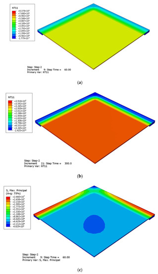
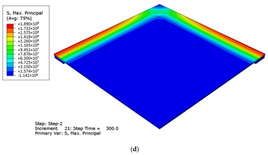
Figure 10.
Evolution of (a,b) temperature and (c,d) stress peaks in glass due to thermal loading (ABAQUS/Standard), after 60 s (a,c) and 300 s (b,d) in fire conditions. Legend in °C and Pa.
The progressive propagation of stress peaks due to thermal loading is also presented in Figure 11, in the form of vector plots of maximum principal tensile stresses. From the selected contour plots it is possible to see the combined effect deriving from the out-of-plane bending mechanical analysis of the panel, as well as from its thermal exposure that involves the modification of material properties. At the beginning of the fire exposure stage, the maximum stress is cumulated in the middle of the pane, and this is mostly in line with a traditional structural analysis of the panel at room temperature. Measured stress peaks can be observed in the order of 24 MPa after 20 s (Figure 11b). Besides, the abrupt temperature increase leads to the sudden modification of mechanical properties of glass (Young’s modulus included, as in Figure 4), and thus to the consequent flexural stiffness redistribution in the panel, with the effect of a variable stress pattern in the overall time interval of fire exposure. The example in Figure 11c shows, for example, that after 60 s the stress peak in glass is still in the order of 24 MPa, but the edge stress level can be now compared to the stress regime at the center of glass. Such a scenario derives from a temperature peak in the order of 350 °C, that roughly corresponds to a maximum 5.4% decrease of Young’s modulus from Figure 4. Accordingly, the measured stress peaks gradually move towards the edges of the examined system.
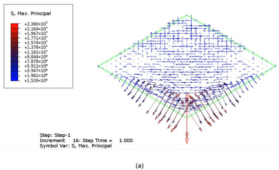
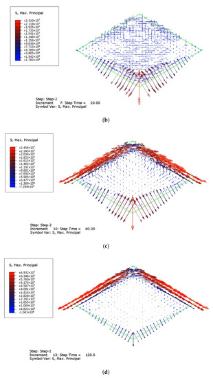
Figure 11.
Evolution of stress peaks in glass due to thermal loading (ABAQUS/Standard), after (a) 1 s, (b) 20 s, (c) 60 s, and (d) 120 s in fire conditions. Legend in Pa.
6.2. Control Point Analysis
The detailed analysis of temperature and stress peaks in glass is presented in Figure 12 and Figure 13, where the evolution in a selection of key control points is presented. While point D was set to coincide with the center of glass panel (bottom surface), the measurements for A, B, C were set in the region of the edge restraints, on the coldest and hottest portions of glass. A schematic representation can be found in Figure 12.
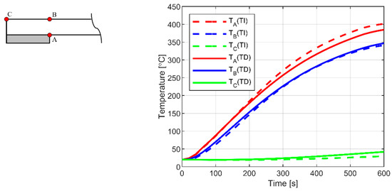
Figure 12.
Temperature history (at selected control points) for 5 mm glass pane. Notation: TI—temperature independent; TD—temperature dependent material properties (ABAQUS/Standard).
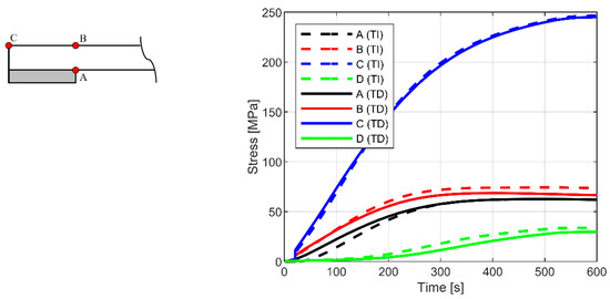
Figure 13.
Stress history (at selected control points) for 5 mm glass pane. Notation: D—point in the middle of pane; TI—temperature independent; TD—temperature dependent material properties (ABAQUS/Standard).
It is worth noting, for the proposed plots, the effect due to TI or TD thermo-physical and mechanical properties of glass, for both the exposed and unexposed portions of the panel close to the edges supports. Globally, for the explored configuration, the temperature sensitivity of material properties was estimated in a moderate % scatter, compared to the temperature and stress peak predictions at a given point, with constant (TI) input parameters, respectively (Figure 14 and Figure 15).
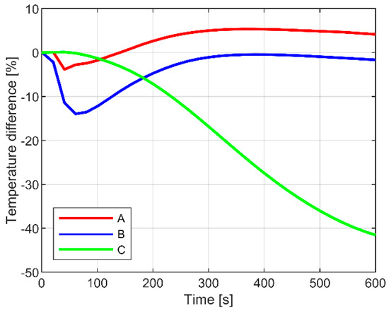
Figure 14.
Temperature sensitivity study at selected control points (ABAQUS/Standard).
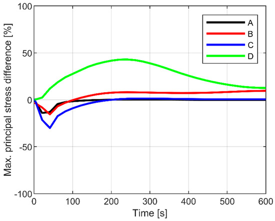
Figure 15.
Maximum principal stress sensitivity study at selected control points (ABAQUS/Standard).
7. Failure Detection
7.1. Thermal Exposure
Following the discussion of available methods (Section 4), the failure condition was first detected for the glass panel under thermal exposure only. To this aim, both the TEMP and STRESS approaches were taken into account, under the assumption of TI and TD material properties for glass.
The typical result is shown in Figure 16, in the form of failure limit condition as a function of the exposure time. The figure shows the overall trend of the failure condition prediction, where the limit value of y-axis “1” represents the nominal failure of the panel (depending on the assumed TEMP or STRESS approaches). Both the TEMP and STRESS methods are generally in line for the relatively simple case study system, but the STRESS approach clearly results in a limited failure time, compared to the TEMP methodology. The difference is measured at collapse in the order of ≈40 s. In addition, it can be also noted that the TD material properties manifest, for both the STRESS and TEMP approaches, in a further reduction of the predicted failure time, thus confirming the weakness of simplified calculation tools that are based on ideally constant material properties only.
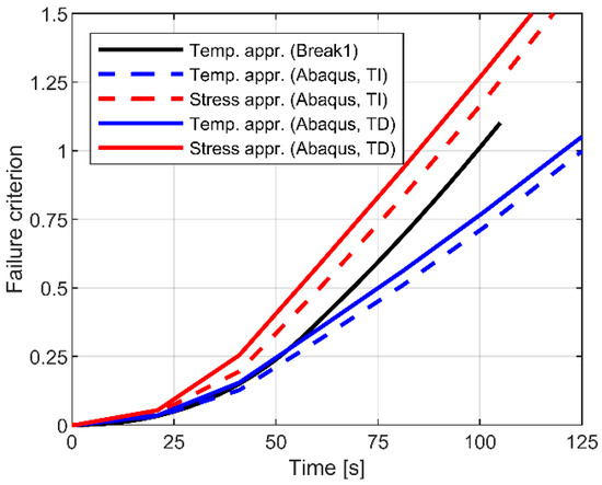
Figure 16.
Comparison of failure criteria (TEMP vs. STRESS approach) for 5 mm glass pane. Notation: TI—temperature independent; TD—temperature dependent material properties.
Finally, regarding the BREAK1 predictions, the collected results lie between the FE numerical estimates, and this finding further suggests the lack of detail refinement for the region of restraints, due to the intrinsic limits of the tool.
7.2. Superimposed Mechanical Loads
In the study, numerical superposition of thermal and mechanical stress is adopted. In such a solving approach, stresses resulting from thermal and mechanical analysis are superimposed in the integration points of each FE assembly.
Figure 17 presents a comparison of different approaches for the determination of breakage time of 5 mm thick panel made of annealed float glass exposed to ISO 834-1 fire and subjected to out-of-plane sustained load. The horizontal axis shows the expected failure time, while the vertical axis presents the amplitude of breakage load at room temperature (20 °C). This means that the loading conditions in Table 2 are compared together as a function of the calculated failure time. In presence of thermal exposure only (y = 0), it is possible to see that the collected results highly depend on the selected failure approach, as well as on the assumption of TI and TD material properties for glass. As such, they are spread over large range of breakage time scenarios (from 74 to 125 s). This finding results in an average failure time of ≈99.5 s that can represent certainly a severe influencing parameter for verification and design considerations. The most conservative approach for the examined system, as shown in Figure 17, is the method presented in prEN thstr:2004 (with minimum effects due to TI or TD material properties). At the same time, the least conservative solution in Figure 17 results from the FE simulations herein performed (with “TEMP” method and TI properties). Modifications in the amplitude of sustained loads from Table 2 can be appreciated for plots with y > 0, and thus necessarily referred to the “STRESS” method.
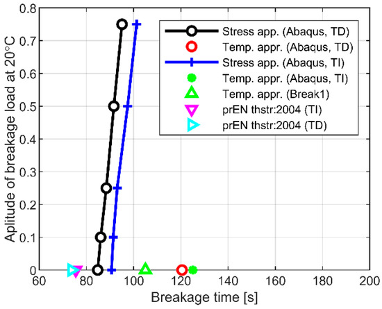
Figure 17.
Comparison of different approaches for determination of breakage time of 5 mm pane made of annealed float glass exposed to ISO 834-1 fire.
Surprisingly, the FE study shows that applying mechanical load to the pane increases the failure time and allows the pane itself to withstand longer the fire exposure. Almost the same trend and failure time increase can be observed in presence of TI or TD material properties.
This finding can be explained by the fact that the stress peaks at edges are reduced by compression forces due to the out-of-plane large-deflection behaviour of the pane subjected to the imposed mechanical load. A fundamental condition to overcome these results, however, is that the region of edge restraints is not directly exposed to fire. Figure 18, in this regard, presents some additional FE results for the pane subjected to mechanical loads only at room temperature (20 °C). The graph shows the magnitude of principal compression stress at the edge of glass, as a function of the amplitude of the imposed sustained load (as a ratio of the failure load qR,0). Even limited in magnitude, the collected stress values progressively increase with the amplitude of the pressure load and the corresponding out-of-plane bending deflection.
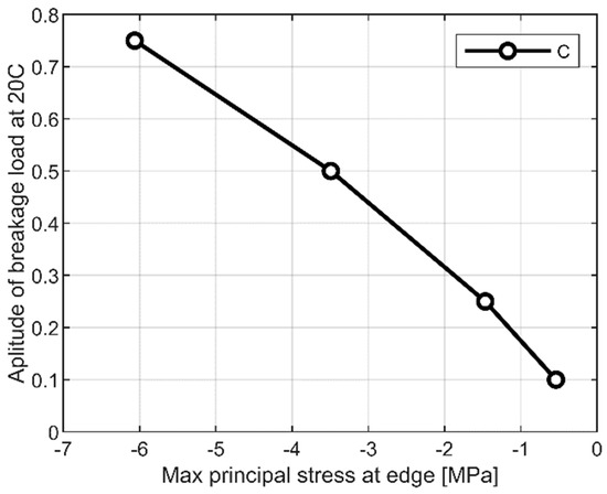
Figure 18.
Principal compressive stress at the edge (control point C), as a result of second order effects (ABAQUS/Standard).
Moving back to Figure 17, it is thus easy to recognize how the compressive stress peaks from FE simulations superimpose with the principal tensile stresses due to the thermal exposure. In conclusion, the final result is a reduced peak that governs the “STRESS” approach response and suggests an improved fire resistance capacity of the same panel. It should be however emphasized that this finding is valid for the considered case with its intrinsic limitations, such as protected boundary restraints, loading scheme and geometrical details (such as edge finishing, size, thickness, etc.). As far as the loading and boundary conditions can fit with the study herein presented, the comparative results can represent a feedback for further calculations. Moreover, the same verification concepts can be easily extended to laminated glass panels where the resisting section is still composed of ordinary glass, but multiple bonded layers can ensure even more residual capacity than the current case study system.
8. Conclusions
The paper investigated the phenomena of glass failure due to exposure to thermal scenario (standard fire) and sustained mechanical loads. To this aim, Finite Element (FE) numerical simulations aimed at supporting the research and sensitivity analysis were discussed in terms of input parameters and failure detection methods for out-of-plane loaded glass panels in fire. To this aim, numerical predictions from the BREAK1 tool were also taken into account. The attention was hence focused on the failure detection of out-of-plane loaded glass panels in terms of “temperature approach” (“TEMP”) or “stress approach” (“STRESS”) fracture mechanisms, where:
- For “TEMP”, the expected failure time is derived based on the difference between the average temperature over the central pane and the coldest temperature on the edge;
- For “STRESS”, the failure time is calculated from the cumulative stress field due to the imposed thermal and mechanical loads, and the comparison of extreme values of maximum principal stress are compared to the allowable material strength.
It should be emphasized that the presented outcomes are valid for the considered case with its limitations, such as boundary conditions, loading scheme and geometrical details. From the performed parametric studies, in any case, the following conclusions can be drawn:
- Existing conventional methods for the detection of failure time in load-bearing members and systems due to fire exposure are well-known to be simplified, and thus require more sophisticated analyses in support of refined design;
- Major limits are associated to their application to structural glass elements that are expected to sustain accidental thermal loads but also (as it is in many cases of load-bearing applications in buildings) superimposed design mechanical loads;
- Both the “TEMP” and “STRESS” approaches should be necessarily taken into account, in order to represent a more realistic temperature and stress scenario for the glass member to verify;
- The use of temperature-dependent material properties for glass in place of their actual degradation with high temperatures may considerably affect the predicted failure time;
- The Young’s modulus of glass, in particular, largely affects the deflection and stress evolution in glass, and thus the expected failure time for a given element;
- For the examined loading and boundary condition, differing from expectations, the superimposed effect of fire (on the bottom side) and mechanical loads (vertical, downward) was found to result in a beneficial cumulative effect of tensile and compressive stress peaks at the edges. As a final observation, the failure time can increase with increasing mechanical load amplitudes;
- Besides, a strategic role derives from boundaries and restraints, that should be kept protected from fire exposure to avoid premature breakage;
- Finally, the current numerical outcomes are necessarily expected to be further extended to laminated glass sections composed of multiple layers, as well as to different scale ratios.
Author Contributions
This research paper results from a joint collaboration of both the involved authors. In particular, M.K. took care of the FE numerical simulations, while both M.K. and C.B. supported the post-processing stage, the discussion of results and the paper drafting. All authors have read and agreed to the published version of the manuscript.
Funding
This research received no external funding. Moreover, the APC was funded by MDPI (invited submission for the corresponding author).
Data Availability Statement
Data supporting this research study will be shared upon request.
Acknowledgments
MDPI is gratefully acknowledged for this invited submission.
Conflicts of Interest
The authors declare no conflict of interest.
References
- CEN/TC 250. prCEN/TS xxxx-1: 2019-In-Plane Loaded Glass Components; European Committee for Standardization (CEN): Brussels, Belgium, 2019. [Google Scholar]
- CEN/TC 250. prCEN/TS xxxx-2: 2019-Out of-Plane Loaded Glass Components; European Committee for Standardization (CEN): Brussels, Belgium, 2019. [Google Scholar]
- Bedon, C. Structural Glass Systems under Fire: Overview of Design Issues, Experimental Research, and Developments. Adv. Civ. Eng. 2017, 2017, 1–18. [Google Scholar] [CrossRef]
- Bedon, C.; Louter, C. Thermo-mechanical numerical modelling of structural glass under fire-Preliminary considerations and comparisons. Challenging Glass Conf. Proc. 2018, 6, 513–524. [Google Scholar]
- Bedon, C.; Kozlowski, M.; Honfi, D. Thermal assessment of glass facade panels under radiant heating-Experimental and preliminary numerical studies. J. Facade Design Eng. 2018, 6, 49–64. [Google Scholar]
- Kozłowski, M.; Bedon, C.; Honfi, D. Numerical Analysis and 1D/2D Sensitivity Study for Monolithic and Laminated Structural Glass Elements under Thermal Exposure. Materials 2018, 11, 1447. [Google Scholar] [CrossRef] [PubMed]
- Tedim, F.; Leone, V.; Amraoui, M.; Bouillon, C.; Coughlan, M.R.; Delogu, G.M.; Fernandes, P.; Ferreira, C.; McCaffrey, S.M.; McGee, T.K.; et al. Defining Extreme Wildfire Events: Difficulties, Challenges, and Impacts. Fire 2018, 1, 9. [Google Scholar] [CrossRef]
- Maranghides, A.; Mell, W. A Case Study of a Community Affected by the Witch and Guejito Wildland Fires. Fire Technol. 2011, 47, 379–420. [Google Scholar] [CrossRef]
- Koo, E.; Pagni, P.J.; Weise, D.R.; Woycheese, J.P. Firebrands and spotting ignition in large-scale fires. Int. J. Wildland Fire 2010, 19, 818–843. [Google Scholar] [CrossRef]
- Ott, C.W.; Adhikari, B.; Alexander, S.P.; Hodza, P.; Xu, C.; Minckley, T.A. Predicting Fire Propagation across Heterogeneous Landscapes Using WyoFire: A Monte Carlo-Driven Wildfire Model. Fire 2020, 3, 71. [Google Scholar] [CrossRef]
- Wang, Y.; Wang, Q.; Fan, X.; Sun, J. Simulating the Thermal Response of Glass Under Various Shading Conditions in a Fire. Procedia Eng. 2013, 62, 702–709. [Google Scholar] [CrossRef]
- Wang, Y.; Wang, Q.; Shao, G.; Chen, H.; Sun, J.; He, L.; Liew, K. Experimental study on critical breaking stress of float glass under elevated temperature. Mater. Des. 2014, 60, 41–49. [Google Scholar] [CrossRef]
- Wang, Y.; Wang, Q.; Wen, J.X.; Sun, J.; Liew, K. Investigation of thermal breakage and heat transfer in single, insulated and laminated glazing under fire conditions. Appl. Therm. Eng. 2017, 125, 662–672. [Google Scholar] [CrossRef]
- Xie, Q.; Cheng, X.; Si, D. Experimental study on critical breakage stress of float glass with different thicknesses under conditions with temperatures of 25 and 200 °C. Fire Mater. 2010, 35, 275–283. [Google Scholar] [CrossRef]
- Wang, Y.; Sun, J.; He, L.; Wang, Q.; Rush, D. Experimental study on fallout behaviour of tempered glass façades with different frame insulation conditions in an enclosure fire. Proc. Combust. Inst. 2019, 37, 3889–3898. [Google Scholar] [CrossRef]
- Hietaniemi, J. Probabilistic Simulation of Glass Fracture and Fallout in Fire; VTT Working Paper 41; VTT Technical Research Centre of Finland: Espoo, Finland, 2005; ISBN 951-38-6593-2. [Google Scholar]
- Dembele, S.; Rosario, R.A.; Wen, J.X. Thermal breakage of window glass in room fires conditions—Analysis of some important parameters. Build. Environ. 2012, 54, 61–70. [Google Scholar] [CrossRef]
- Vedrtnam, A.; Bedon, C.; Youssef, M.; Wamiq, M.; Sabsabi, A.; Chaturvedi, S. Experimental and numerical structural assessment of transparent and tinted glass during fire exposure. Constr. Build. Mater. 2020, 250, 118918. [Google Scholar] [CrossRef]
- Sjöström, J.; Kozłowski, M.; Honfi, D.; Lange, D.; Albrektsson, J.; Lenk, P.; Eriksson, J. Fire Resistance Testing of a Timber-Glass Composite Beam. Int. J. Struct. Glas. Adv. Mater. Res. 2020, 4, 24–40. [Google Scholar] [CrossRef]
- Buchanan, A. The Challenges of Predicting Structural Performance in Fires. Fire Saf. Sci. 2008, 9, 79–90. [Google Scholar] [CrossRef]
- EN 1363-1: 2012. Fire Resistance Tests – Part 1: General Requirements; European Committee for Standardization (CEN): Brussels, Belgium, 2012. [Google Scholar]
- Rackauskaite, E.; Kotsovinos, P.; Jeffers, A.; Rein, G. Computational analysis of thermal and structural failure criteria of a multi-storey steel frame exposed to fire. Eng. Struct. 2019, 180, 524–543. [Google Scholar] [CrossRef]
- Bedon, C.; Fragiacomo, M. Experimental and numerical analysis of in-plane compressed unprotected log-haus timber walls in fire conditions. Fire Saf. J. 2019, 107, 89–103. [Google Scholar] [CrossRef]
- Simulia. ABAQUS Computer Software; Dassault Systemes: Providence, RI, USA, 2020. [Google Scholar]
- Emmons, H.W. The Needed Fire Science. Fire Saf. Sci. 1986, 1, 33–53. [Google Scholar] [CrossRef]
- Li, D.; Li, W.; Wang, R.; Shen, X. Temperature dependence of the three-point bending fracture behavior of soda–lime–silica glass with surface scratch. J. Non-Crystalline Solids 2015, 409, 126–130. [Google Scholar] [CrossRef]
- Minko, N.I.; Nartsev, V.M. Factors affecting the strength of the glass (review). Middle-East J. Sci. Res. 2013, 18, 1616–1624. [Google Scholar] [CrossRef]
- Scholze, H. Glass—Nature, Structure, and Properties; Springer: Berlin, Germany, 1991. [Google Scholar]
- Stanworth, J.E. Physical Properties of Glass; Clarendon Press: Oxford, UK, 1950. [Google Scholar]
- de Sa, J.C. Numerical modelling of glass forming processes. Eng. Comput. 1986, 3, 266–275. [Google Scholar] [CrossRef]
- Fluegel, A.; Earl, D.A.; Varshneya, A.K.; Seward, T.P. Density and thermal expansion calculation of silicate glass melts from 1000c to 1400c. Phys. Chem. Glasses 2008, 49, 245–257. [Google Scholar]
- prEN Thstr: 2004. Glass in Building: Thermal Stress Calculation Method; European Committee for Standardization (CEN): Brussels, Belgium, 2014.
- Foraboschi, P. Analytical modeling to predict thermal shock failure and maximum temperature gradients of a glass panel. Mater. Des. 2017, 134, 301–319. [Google Scholar] [CrossRef]
- BREAK1 Software. National Institute of Standards and Technology (NIST)—Fire Research Division. Available online: https://www.nist.gov/document/break1zip (accessed on 2 February 2021).
- ISO 834-1. Fire-Resistance Tests—Elements of Building Construction—Part 1: General Requirements; International Organization for Standardization (ISO): Geneve, Switzerland, 1999. [Google Scholar]
Publisher’s Note: MDPI stays neutral with regard to jurisdictional claims in published maps and institutional affiliations. |
© 2021 by the authors. Licensee MDPI, Basel, Switzerland. This article is an open access article distributed under the terms and conditions of the Creative Commons Attribution (CC BY) license (http://creativecommons.org/licenses/by/4.0/).