Article

Silicon-Based Solar Brick for Textile Ceramic Technology

1
Department of Architecture, Universitat Internacional de Catalunya (UIC), 08017 Barcelona, Spain
2
Energy & Engineering Business Unit, Leitat, Tecbnological Center, 08225 Terrasa, Spain
3
Tecnalia, Basque Research and Technology Alliance (BRTA), 20730 Azpeitia, Spain
4
Department of Architecture, University of the Basque Country UPV/EHU, 20018 Donostia-San Sebastian, Spain
*
Author to whom correspondence should be addressed.
Ceramics 2025, 8(3), 106; https://doi.org/10.3390/ceramics8030106
Submission received: 8 June 2025 / Revised: 27 July 2025 / Accepted: 12 August 2025 / Published: 15 August 2025

Abstract

Recent advances in prefabricated construction have enabled modular systems offering structural performance, rapid assembly, and design flexibility. Textile Ceramic Technology (TCT) integrates ceramic elements within a stainless-steel mesh, creating versatile architectural envelopes for façades, roofs, and pavements. This study investigates the integration of silicon photovoltaic (PV) modules into TCT to develop an industrialized Building-Integrated Photovoltaics (BIPV) system that maintains energy efficiency and visual coherence. Three full-scale solar brick prototypes are presented, detailing design objectives, experimental results, and conclusions. The first prototype demonstrated the feasibility of scaling small silicon PV units with good efficiency but limited aesthetic integration. The second embedded PV cells within ceramic bricks, improving aesthetics while maintaining electrical performance. Durability tests—including humidity, temperature cycling, wind, and hail impact—confirmed system stability, though structural reinforcement is needed for impact resistance. The third prototype outlines future work focusing on modularity and industrial scalability. Results confirm the technical viability of silicon PV integration in TCT, enabling active façades that generate renewable energy without compromising architectural freedom or aesthetics. This research advances industrialized, sustainable building envelopes that reduce environmental impact through distributed energy generation.

1. Introduction

Recent advancements in construction technology have led to the development of modular systems that combine structural performance, rapid assembly, and design flexibility. Among these, Textile Ceramic Technology (TCT) stands out as a prefabricated dry solution that integrates ceramic elements within a stainless-steel mesh, offering a versatile method for the construction of architectural envelopes. Originally patented in 2011 [1], TCT has proven effective in a wide range of applications, including façades, pavements, and roofing systems. Prefabricated in factory conditions, TCT units are folded (Figure 1a), transported to the site, suspended by means of a steel ‘L’ profile, and fixed to the main structure (Figure 1b) [2].
In contrast to conventional brick wall construction, which involves the time-consuming placement of individual bricks with mortar, TCT enables dry assembly of large ceramic shells ranging from 0.6 to 2 m in width (Figure 1b). This prefabricated approach significantly accelerates construction timelines while ensuring consistency in finish. The continuity of TCT shells across different surfaces (façades, roofs, and grounds [3]) (Figure 1d) minimizes design disruptions at joints and corners, as evidenced in architectural projects such as the TR House [4] (Figure 1c) or the Sant Pau Research Institute [5].
TCT’s adaptability extends to complex geometries. By adding mortar between ceramic joints, the system can be used to construct curved vaults and thin shells, as demonstrated in Casa Mingo [6,7] and House CDS [8]. Both experimental and numerical studies support the structural integrity and mechanical performance of these applications [9,10].
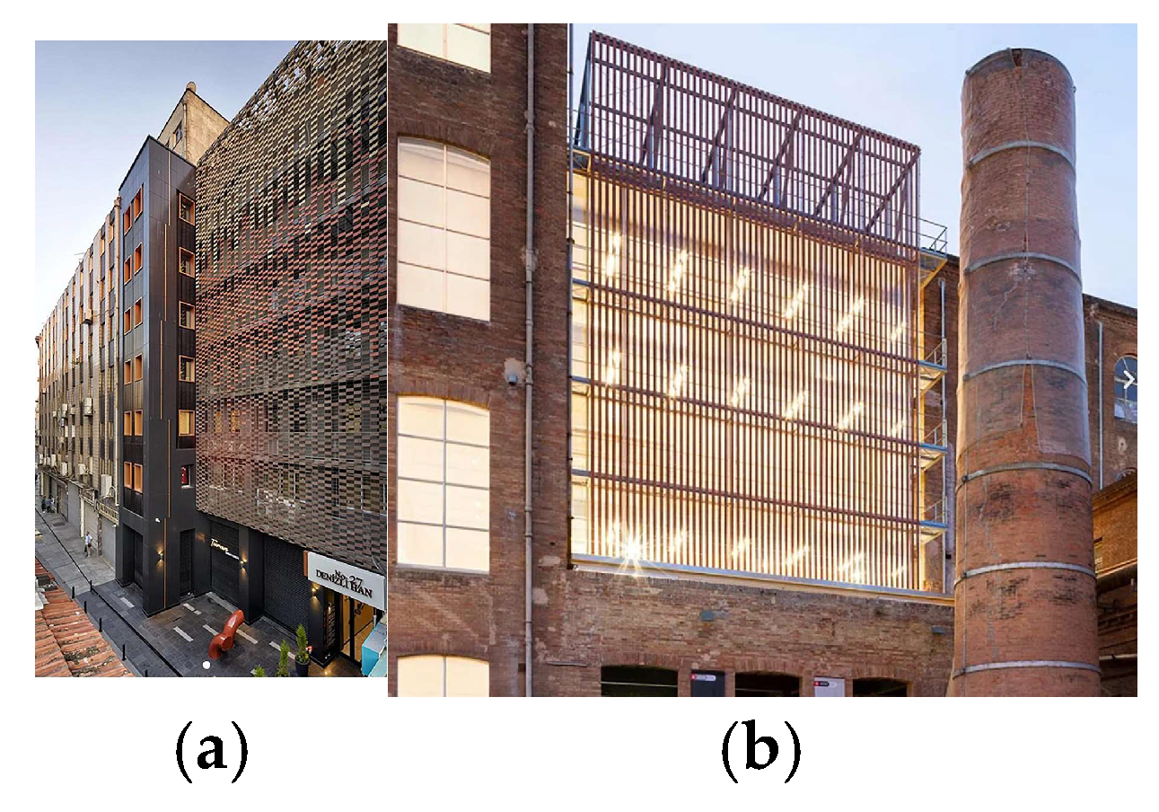
In addition to its functional benefits, TCT allows for diverse architectural expressions. Ceramic components can vary in color, form, and orientation, enabling configurations ranging from uniform layouts to randomized patterns (Figure 2). This flexibility supports not only aesthetic innovation but also functional applications such as latticed screens that offer solar shading.
Ongoing research aims to expand TCT’s capabilities by integrating silicon-based PhotoVoltaic (PV) technology into ceramic components.
The principal challenge lies in integrating silicon PV cells into building façades in a manner that is both aesthetically pleasing and versatile, allowing architects to design varied façades and ensuring full architectural integration, rather than appearing as an applied or superimposed element.
Traditionally, silicon solar cells dominate the photovoltaic sector but are primarily used in rooftop installations (Building-Attached Photovoltaics, BAPV), where aesthetic considerations are less critical due to their characteristic black appearance and rigidity [11,12,13].
In façade applications, second-generation thin-film solar cells—such as amorphous silicon, copper indium gallium diselenide (CIGS), and cadmium telluride (CdTe)—are gaining market share (currently 56%) owing to advantages such as a broader color range, uniform transparency, and reduced weight [14].
Related to the third-generation thin-film solar cells, it is relevant to make note that recent studies [15] have demonstrated that advanced photonic microstructures allow perovskite solar cells to achieve virtually any desired color, offering a promising path for enhancing BIPV aesthetics.
Although crystalline silicon PV cells involve higher manufacturing costs per unit, their superior energy conversion efficiency compensates in large-scale implementations, ultimately resulting in a lower cost per watt installed in utility-scale systems [16].
Another key issue is determining whether numerous small black silicon units, approximately the size of a brick or smaller, can collectively generate an energy output comparable to that of conventional silicon photovoltaic panels.
In this context, it is worth mentioning the work presented in [17], which demonstrates the integration of nanostructured thin-film amorphous silicon solar cells into ceramic tiles. The use of plasma-enhanced chemical vapor deposition (PECVD) in this approach highlights its compatibility with industrial ceramic manufacturing processes.
In line with these advances, the study presented in [18] enhances thin-film silicon solar cells through the application of front coatings that enable long-term self-cleaning properties for outdoor use. By employing low-cost colloidal lithography, microscopic structures are created on a transparent parylene-C layer, generating a superhydrophobic surface that minimizes dirt and water adhesion—thus improving the durability and sustained performance of the device.
Interested readers can find a comprehensive scientometric review of global BIPV research in [19], outlining key trends in commercial product development and implementation challenges, including the emergence of ceramic-based photovoltaics and flexible laminate technologies such as CIGS and OPV. Complementary studies on green building materials further underscore the increasing relevance of innovation clusters—particularly those related to renewable energy integration and thin-film ceramic applications—that align with broader sustainable construction goals [20].
The primary objective of this research is to evolve TCT into a multifunctional system integrating industrial construction methods with renewable energy technologies. By developing silicon PV-compatible ceramic elements, TCT presents a promising approach for creating active, adaptable building envelopes suitable for both new constructions and energy-efficient retrofits.
This article presents research on the design of a silicon solar brick through the development of three full-scale prototypes. The first explores the feasibility of scaling up small, brick-sized silicon modules to building-scale applications; the second refines the design with a focus on construction and potential market implementation; and the third represents a conceptual proposal indicating future research directions. The first two designs have been evaluated experimentally, while the third outlines forthcoming development. Some tests employ alternative methods to better reflect real-world conditions or enable more agile feasibility assessments, given the absence of specific standards for photovoltaic-integrated façade elements, which poses challenges for standardization and validation. Existing patents cover PV roof applications [21,22,23,24,25,26,27], prefabricated solar panels [28], and photovoltaic protection systems [29].
A common challenge is achieving architectural design freedom and versatility, as many components are unique pieces that have not thoroughly considered aesthetics or full integration, limiting the broader application of Building-Integrated Photovoltaics (BIPV).
The development of the Solar Brick (SB) prototype aligns with the fundamental principles of the TCT system, which is conceived as a dry-construction solution based on modularity, reversibility, and ease of maintenance. Each unit (i.e., brick) is designed to be easily removed from the stainless-steel mesh using a simple tool, such as a spatula, allowing for its replacement or repair without requiring specialized labor. This dry assembly approach eliminates the use of adhesives, enabling the separate recovery, reuse, or recycling of both ceramic and photovoltaic components. From the early stages of the design process, the SB has been developed to follow this philosophy, ensuring that the photovoltaic cell can also be removed and replaced with minimal intervention, for example, to address degradation in the edge sealing or to upgrade the cell.
This strategy supports a circular economy model and promotes longevity by allowing damaged or obsolete elements to be replaced individually, without dismantling large sections of the TCT system. Furthermore, the SB integrates photovoltaic elements in accordance with Building Integrated Photovoltaics (BIPV) principles [30,31,32], combining energy generation with architectural coherence.
The embedded PV module has been optimized to balance high energy efficiency with the constraints of construction integration. The overall system is also designed for rapid and standardized installation [33], allowing for uniform assembly by non-specialized personnel.

2. First Prototype

2.1. First Silicon-Based Solar Brick Prototype

The initial design of the solar brick (SB) aims to evaluate whether distributing photovoltaic modules across individual plates leads to significant energy losses. At the same time, it provides an initial opportunity to engage with key aspects of the system, such as physical dimensions, aesthetic compatibility, BIPV, functional performance, and potential design constraints, laying the groundwork for further development and refinement.
The SB integrates a Silicon Photovoltaic Module (SPM) into a 3D-printed ABS (Acrylonitrile Butadiene Styrene) frame, which is affixed to a conventional ceramic brick (193 mm × 96 mm × 30 mm) using four galvanized steel clips. The SPM consists of a 4 mm glass front, a 2 mm monocrystalline silicon cell, and a 0.5 mm backsheet, resulting in a total thickness of 6.5 mm and dimensions of 96 mm × 96 mm × 17 mm. A graphite rear finish enhances visual quality.
The PV cell delivers approximately 1081 mW of maximum power, with an energy conversion efficiency of 22%, an open-circuit voltage (Voc) of 7.56 V, and a short-circuit current (Isc) of around 200 mA. Electrical interfacing uses high-voltage-rated cable grommets and outdoor-grade locking connectors to ensure sealing and mechanical robustness.
The design allows for either partial (Figure 3a) or full surface (Figure 3b) coverage of the brick, optimizing architectural integration by combining ceramic textures and colors with the dark silicon surface. A prototype assembly embeds six identical SPMs into a TCT mesh (Figure 3c), forming three fully covered solar bricks, which are electrically interconnected to create a functional photovoltaic unit.
The primary objective is to compare, through experimental testing, the energy conversion efficiency and electrical behavior of a single SPM with that of an interconnected configuration comprising three SPM units—referred to here as the SPM-Mesh. This comparison aims to determine whether the integration and parallel connection of multiple modules result in significant performance losses.
To minimize efficiency degradation under non-uniform irradiance, the photovoltaic cells are connected in parallel. configuration permits each cell to operate independently, thereby reducing performance losses and preventing damage to the remainder of the array under partial shading conditions commonly encountered in real-world scenarios.

2.2. Experimental Tests

This section presents the electrical performance evaluation of a single Silicon Photovoltaic Module (SPM), hereafter referred to as SPM-1 (Figure 3b), and a mesh assembly comprising three ceramic pieces fully covered by SPM units, referred to as SPM-Mesh (Figure 3c).
Electrical characterization is performed by recording the current-voltage (I-V) curves of both the SPM-1 and the SPM-Mesh under two different conditions: controlled indoor testing in a climatic chamber and outdoor testing under natural sunlight (Figure 4).
The experimental tests conducted constitute a preliminary and coarse evaluation intended to provide a first-order estimation of energy conversion efficiency and electrical performance. While not exhaustive, these tests offer an initial indication of potential efficiency losses resulting from the integration and interconnection of multiple photovoltaic modules.

2.2.1. Climatic Chamber

Measurements are conducted in a climatic chamber at 25 °C using a halide lamp perpendicular to the cell surfaces (Figure 4a). Although the standard incident radiation for solar cell efficiency tests is 1000 W/m2, these measurements use 800 W/m2 to better simulate typical high outdoor illumination during the testing period, allowing for more accurate result comparisons. Table 1 summarizes the electrical parameters obtained.
The results indicate that the SPM-Mesh exhibits a reduction of approximately 22% in energy conversion efficiency compared to the single SPM-1 module. This decrease is mainly due to increased series resistance (Rs) and reduced shunt resistance (Rsh) in the mesh configuration, attributed to the additional electrical interconnections and leakage currents, respectively.

2.2.2. Outdoor Performance

Outdoor measurements are conducted on a rooftop solar platform under two irradiance conditions: high irradiance (RA ≈ 700 W/m2, sunny) and low irradiance (RB ≈ 100 W/m2, cloudy). Tests are carried out using both a solar tracker and a fixed vertical mounting configuration (Figure 4b). The corresponding electrical parameters are summarized in Table 2.
Under outdoor conditions, both SPM-1 and SPM-Mesh show reduced current output and efficiency relative to indoor testing, mainly due to the lower incident irradiance (~60 W/m2 less). Notably, the efficiency loss between the single module and the mesh under natural illumination decreases to approximately 10%, likely because outdoor ventilation reduces thermal stress and related losses.
Additionally, Table 3 compares electrical parameters for the SPM-Mesh prototype tested with a solar tracker and in a static vertical position, relevant for typical façade installations.
No significant performance differences are observed between the tracking and static vertical conditions, confirming the prototype’s suitability for façade applications.

2.3. Prototype 1: Conclusions

Comparative tests between the individual photovoltaic module (SPM-1) and the photovoltaic mesh assembly (SPM-Mesh) reveal an efficiency loss of approximately 22% under controlled laboratory conditions. This reduction is attributed to increased series resistance and reduced shunt resistance, both associated with the electrical interconnection and assembly of the system.
Under real outdoor conditions, this loss is reduced to around 10%, likely due to improved ventilation and lower thermal accumulation. Additionally, no significant differences are observed between the static vertical configuration and the use of a solar tracker, confirming the suitability of the design for façade applications.
Notably, the prototype achieves an efficiency of 17.5% under controlled conditions, which is relatively high and comparable to that of commercial crystalline silicon modules.
These results indicate that, despite moderate performance losses, the mesh integration approach is technically viable and functionally appropriate for architectural photovoltaic systems.
Nevertheless, despite its promising electrical performance, the prototype is ultimately deemed unsuitable for full architectural integration (BIPV) due to aesthetic and physical limitations. The dominant black appearance of crystalline silicon and the module’s thickness—nearly half that of the brick—undermine its visual integration. Therefore, although technically feasible, the current design requires further refinement to meet the formal and visual requirements of architectural applications.

3. Second Prototype

3.1. Second Silicon-Based Solar Brick Prototype

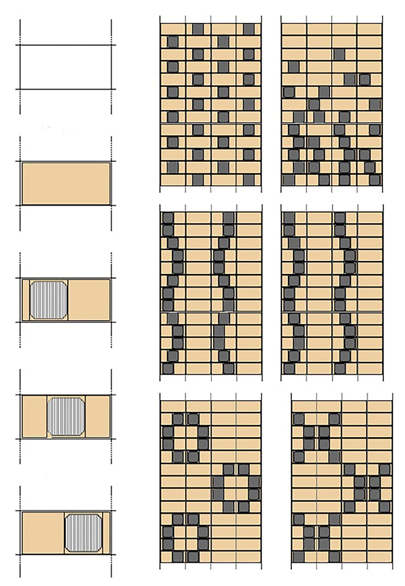
One of the main issues with the first prototype is that the solar photovoltaic module (SPM) is merely attached to the surface of the brick rather than being fully integrated. To address this, the current design incorporates a groove within the ceramic brick to fully embed the PV cell, ensuring its surface is flush with the brick and both elements lie on the same finished plane (Figure 5a). This groove may be positioned centrally or offset to the left or right, enabling greater compositional flexibility and enhanced design possibilities through the use of varying ceramic colors, as illustrated in Figure 6.
The extrusion manufacturing process facilitates rapid and cost-effective production of these ceramic units with integrated grooves, balancing mechanical strength and functional needs. Specifically, the groove includes a recessed central section designed to accommodate the PV wiring, which is coated with silicone to protect the soldered connections and ensure durability under outdoor conditions (Figure 5b).
The PV module is fixed within the groove through compression and friction, assisted by the perimetral sealing frame of the module (Figure 5c).
The retaining lips of the groove feature a rounded (blunt) profile with dimensions carefully balanced to avoid shading the active PV surface while ensuring proper clay flow during extrusion. This geometry also reduces stress concentration points, thereby minimizing the risk of fractures from minor impacts or handling. Rounded retaining lips not only minimize shading but also improve structural integrity, facilitating ease of assembly and maintenance within the BIPV system.
The PV cell dimensions are 140 mm × 140 mm × 4.5 mm, making it larger than in the initial design. The aim is to increase the active area while maintaining a square shape. Accordingly, the ceramic tile dimensions are also increased to 243 mm × 140 mm × 30 mm. It is a monocrystalline silicon solar cell. The photovoltaic cell is characterized under Standard Test Conditions (STC), which include an AM1.5 solar spectrum, an irradiance of 1000 W/m2, and a cell temperature of 25 °C (Table 4).
To assess the durability, electrical performance, and mechanical integrity of the photovoltaic panels integrated into the TCT system, a series of accelerated tests based on the IEC 61215-2 standard [34] is conducted.

3.2. Experimental Tests

Standard testing methodologies habitually evaluate the behavior of individual specimens under isolated environmental or mechanical conditions. In contrast, the present study applies a sequential series of tests to each specimen, simulating the cumulative degradation that the solar brick may experience over its service life. This approach enables a more representative assessment of the prototype’s performance and reliability under real-world conditions.
The experimental sequence comprises the following tests:
  • Damp-Heat Test (DH1000)
  • Dynamic Wind Load Test (WIND)
  • Hail Impact Test
  • Thermal Cycling Test (TC50)
  • Humidity Freeze Test (HF10)
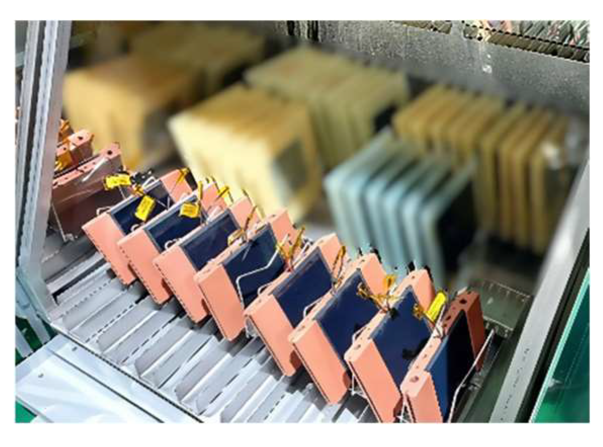
A total of eight specimens are tested: four incorporating a rubber-based (RB) perimetral sealing frame and four a textile-based (TB) frame (Figure 7). These sealing frames are designed to act as a protective barrier between the PV element and the external environment, mitigating the ingress of moisture, water, or ice and thereby reducing the risk of degradation. The experimental comparison focuses on the effectiveness of each sealing solution in maintaining PV performance under combined environmental stressors.
Tests 1, 4, and 5 are conducted in accordance with the IEC 61215-2 standard [34]. For wind loading, a dynamic wind load test is employed instead of the conventional static pressure test, as described in UNE-EN 12179 [35] or ASTM E330 [36]. This decision reflects the greater relevance of fluctuating aerodynamic loads and potential resonance effects in lightweight, ventilated façade systems.
In the case of hail impact, the procedure outlined in IEC 61215-2 entails significant technical and logistical limitations related to projectile generation, control of velocity, and safety considerations. Therefore, a simplified impact method is adopted, calibrated to approximate the energy levels and impact characteristics specified by the standard, while ensuring experimental feasibility.
Electroluminescence (EL) inspections are performed both before and after the testing sequence to detect microcracks or latent defects potentially induced by environmental stresses. Electrical parameters are likewise measured pre- and post-testing. The complete set of results is presented and analyzed in Section 3.3, allowing for the assessment of performance degradation due to cumulative exposure.
Table 5 summarizes the testing sequence applied to each specimen. “SB” denotes Solar Brick, while “TB” and “RB” indicate Textile-Based and Rubber-Based sealing frames, respectively, followed by the specimen identifier.
It must be pointed out here that the instability observed during testing in the maximum power point (Pmax) measurements is attributed to partial oxidation of the cable conductors, resulting in variations in series resistance within the circuit. However, the available data do not allow determination of whether this oxidation occurred prior to or during the testing procedures. Importantly, this issue is related to insufficient protection of the cable terminals after cutting, despite the use of insulating tape, and is not inherent to the solar brick itself. Consequently, short-circuit current (Isc) is adopted as the primary performance metric, as it is less susceptible to variations in series resistance and thus provides more reliable evaluation results.

3.2.1. Damp Heat Test

The objective of this test is to check if the module can withstand long periods of heat and humidity without losing performance or being damaged.
The module is exposed to 85 °C and 85% relative humidity for 1000 h in a controlled climatic chamber (Figure 8), simulating aging due to moisture in accordance with IEC 61215-2 [34]. This accelerated aging test evaluates the long-term resistance of the module to moisture ingress and potential degradation of materials, particularly encapsulants, adhesives, and electrical insulation. Current and power are measured before and after to detect degradation.
No significant defects are observed on the modules, except for sample SB_RB_01, where a photovoltaic (PV) cell detaches from the brick due to degradation of the silicone adhesive sealant. All modules pass the electrical insulation test, with the acceptance criterion being a variation in short-circuit current (ΔIsc) of less than 5%, which all samples meet. The maximum power (Pmax) exhibits minor variations, with some slight losses noted in certain modules (see Section 3.3).

3.2.2. Dynamic Wind Load Test

This study evaluates the behavior of SB specimens under dynamic wind loads replicating real-world conditions. Unlike standard static tests, which apply uniform pressure to assess deformation and failure, dynamic testing generates variable, turbulent airflow to capture vibrations, resonance, detachments, and fatigue resulting from cyclic loading.
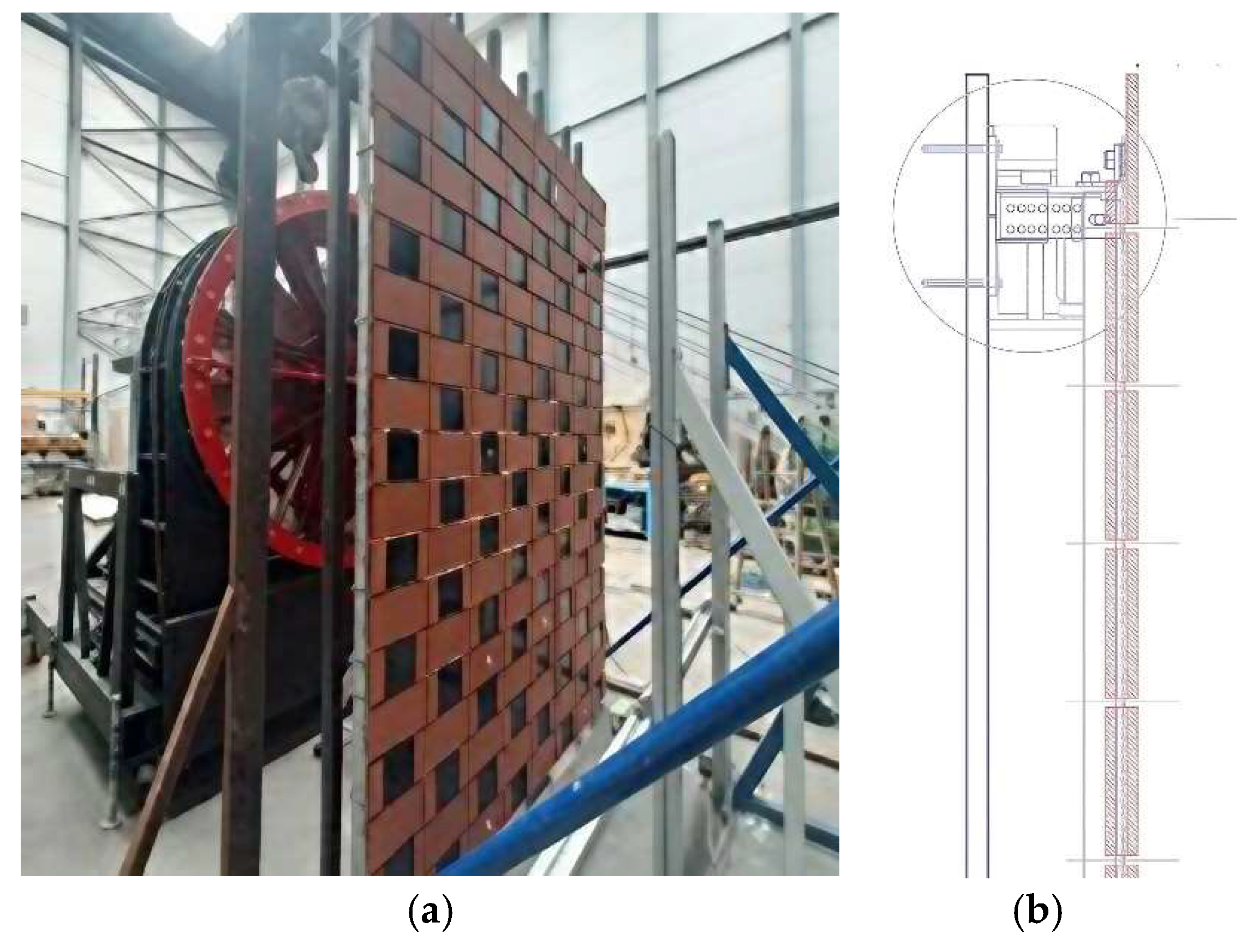
Four SB specimens (SB_RB_01, SB_RB_02, SB_TB_01, SB_TB_02) are integrated into a full-scale TCT mesh (2.00 m × 2.98 m, Figure 9a), positioned near to the stiffest areas reinforced by stainless-steel anchors, as these represent the most critical points for deformation (Figure 9b).
A calibrated 2 m diameter fan (Figure 9a) produces wind speeds from 16.7 to 100 km/h over six levels (Table 6), following EAD 090062 [37] and AAMA 501.1-17 [38] standards. Each stage involves five minutes of wind exposure and one minute of unloading; ambient conditions are controlled at 20 ± 10 °C and 60 ± 20% RH.
No voltage drops or damage were observed during or after testing, and electrical characterization confirmed stable photovoltaic performance under dynamic loading. Despite the fan’s limited power relative to the system scale, the mesh showed substantial robustness, withstanding 100 km/h winds without damage, suggesting capacity for greater deformation before failure.

3.2.3. Hail Impact Test

This study examines the behavior of SB modules under hail-like impacts, following the IEC 61215-2 [34] standard with adaptations due to technical and logistical constraints.
The hail impact test outlined in IEC 61215-2 poses notable technical and logistical challenges [39,40]. The standard test requires near-perfect ice spheres, precisely stored and handled to prevent cracking, which must be launched at controlled velocities. This procedure is complex, costly, and challenging for small modules such as those studied (140 mm × 140 mm), as the standard specifies 11 impact points that do not fit the module dimensions.
To overcome these challenges, a free-falling steel ball with kinetic energy equivalent to the specified hail impacts is employed. This alternative, supported by previous research [41,42] and standards such as UNE-EN 13583 [43] and UNE-EN 9806 [44], enables a rigorous yet efficient testing approach.
Table 7 shows the correspondence between the masses and diameters of the ice spheres and steel balls, as well as the hail ball speed and the steel ball drop heights required for the latter to produce an impact energy comparable to that of the ice on the SB.
During testing, each SB specimen is firmly clamped by its ceramic edges, leaving the photovoltaic cell area unobstructed for assessment. Steel balls are dropped from calibrated heights to simulate various impact energy levels (2 to 7.7 joules). A total of four specimens are tested: two framed with RB and two with TB.
Results demonstrate that specimens withstand impacts up to 2 joules without visible damage (Figure 10a). However, at 7.7 joules, brittle fractures occur in ceramic plates and photovoltaic glass, causing structural failure (Figure 10b,c). Table 8 summarizes the results obtained and the specimens tested.

3.2.4. Thermal Cycling Test

The thermal cycling test, performed in the same programmable climatic chamber used for the Damp Heat and Humidity Freeze tests, simulates extreme environmental conditions for accelerated aging evaluation. Following IEC 61215-2 procedures, it assesses the impact of repeated temperature fluctuations on PV module performance, which can cause material expansion and contraction leading to microcracking, delamination, and fatigue.
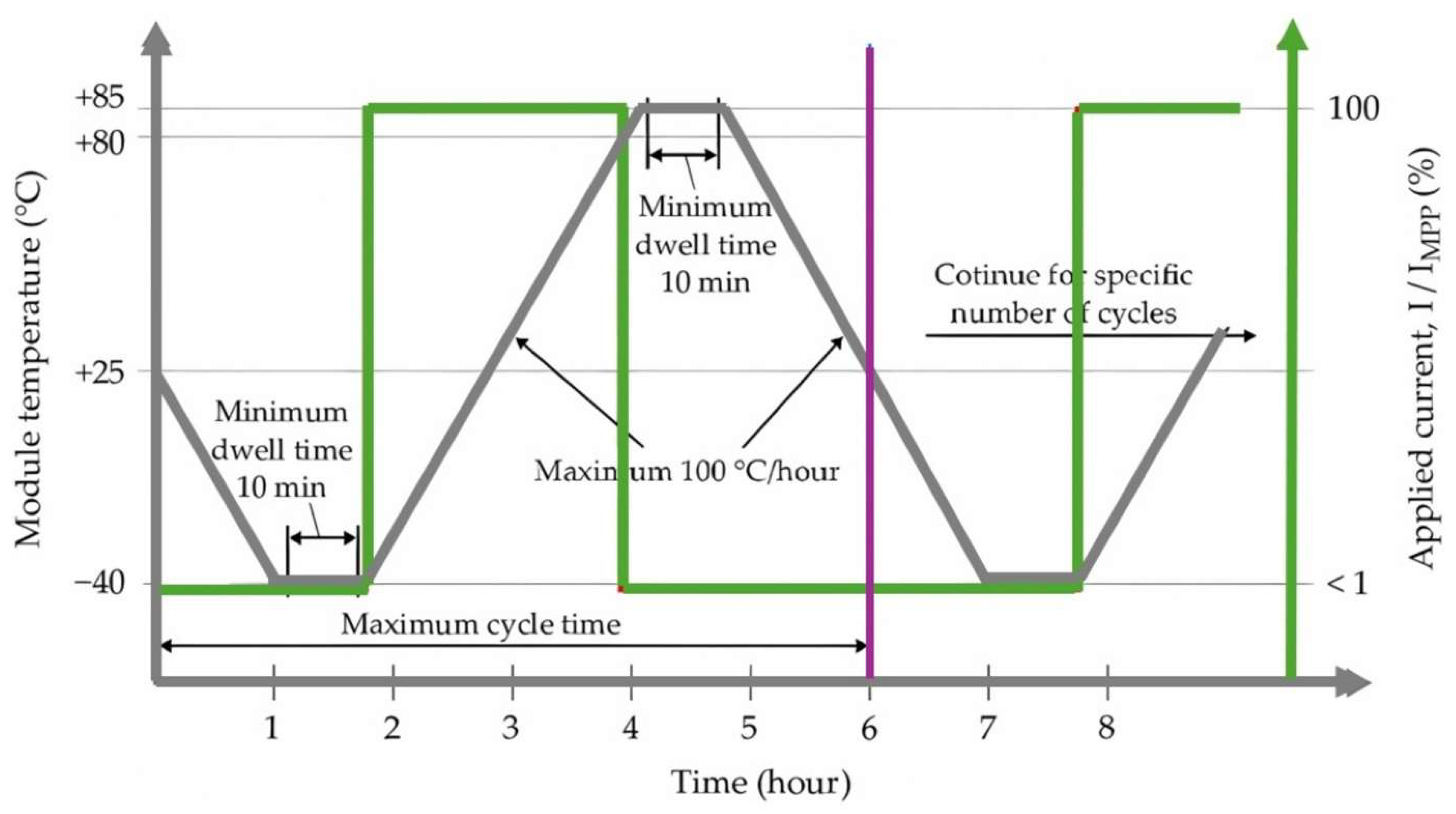
The test consists of 50 thermal cycles between −40 ± 2 °C and +85 ± 2 °C, with a maximum ramp rate of 100 °C/h and minimum 10-min dwell times at each extreme (Figure 11). A continuous current specific to the PV technology is applied during heating and reduced during cooling (≤1% of the STC peak power) and temperature extremes. Temperature sensors monitor each module’s thermal response. After cycling, modules stabilize for at least one hour under controlled ambient conditions (23 ± 5 °C; relative humidity < 75%) before electrical characterization.
The results indicate that all tested modules meet the acceptance criteria defined in IEC 61215-2. The short-circuit current (Isc) remains highly stable, with all deviations (ΔIsc) falling well within the ±5% tolerance, demonstrating electrical durability under thermal stress. All modules are deemed to have passed the IEC 61215-2 thermal cycling qualification test (Table 9, Section 3.3).

3.2.5. Humidity Freeze Test

The humidity-freeze test, conducted in accordance with IEC 61215-2, evaluates the durability of PV modules under prolonged heat and humidity followed by freezing, simulating realistic environmental stress from moisture ingress and thermal contraction. Unlike thermal shock tests, it applies gradual temperature changes. Modules are placed on thermally non-conductive supports to ensure proper airflow and isolation. Temperature sensors are affixed near the center of each module, and a low-level direct current (≤0.5% of STC Isc or a minimum of 100 mA) is applied to monitor continuity.
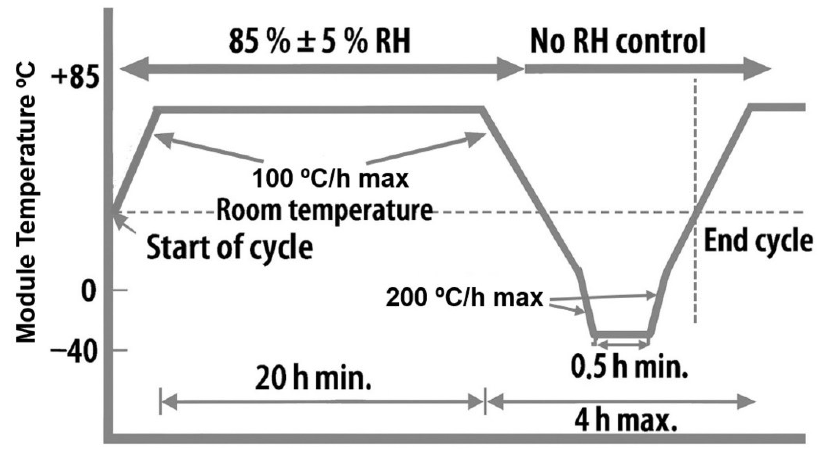
The test consists of ten cycles alternating between 85 °C high Relative Humidity (RH) followed by sub-zero temperatures, strictly adhering to standard-defined tolerances (Figure 12). Module temperature, current, and voltage are continuously monitored throughout. After testing, modules stabilize under ambient conditions (23 ± 5 °C, RH < 75%) for 2–4 h, followed by I-V measurements. These results are compared to pre-test values, obtained after the modules have undergone prior damp heat, wind, hail, and thermal cycling exposures.
According to IEC 61215, the humidity-freeze test is passed if key electrical parameters (Isc and Pmax) do not vary by more than −5% from their initial values. All tested modules remain within this threshold. No visual defects or insulation failures are observed, confirming compliance with safety and performance standards. Despite prior mechanical and thermal stress, the modules maintain stable performance and structural integrity under cyclic environmental loading (Table 9, Section 3.3).

3.3. Prototype 2: Results and Conclusions

3.3.1. Electroluminescence Inspection

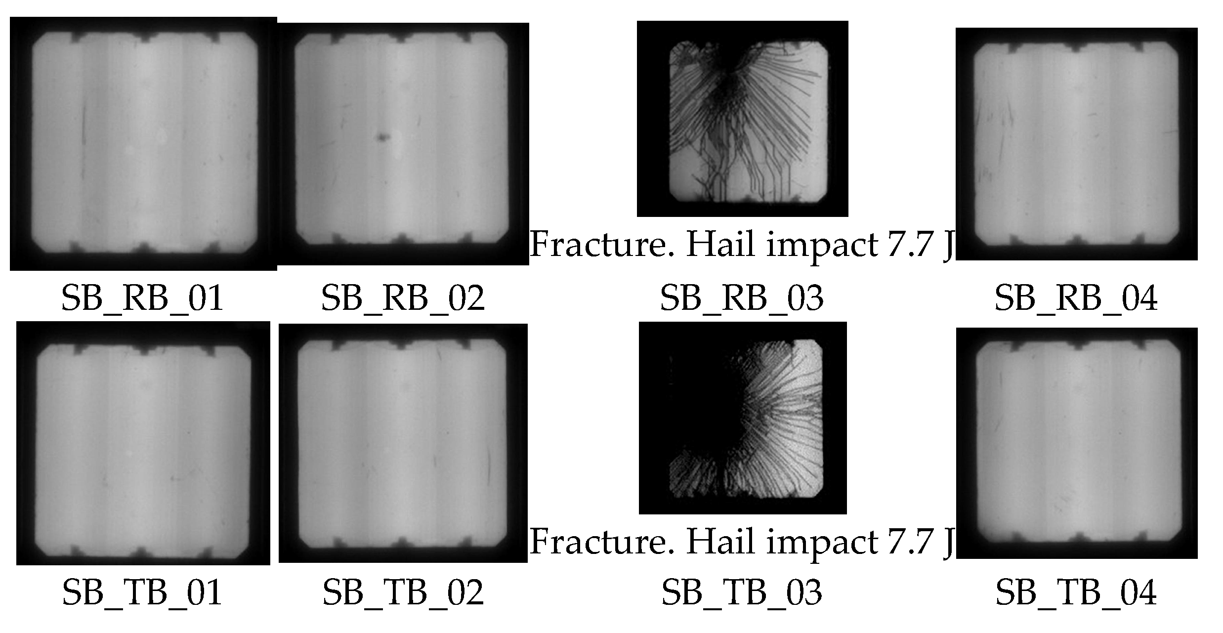
As can be observed (Figure 13), electroluminescence (EL) imaging conducted after the sequence of experimental tests reveals no significant microcracks or cell degradation in any of the tested modules, thereby corroborating the electrical findings. The only exception is observed in those modules that suffer structural damage under hail impacts with an energy of 7.7 J, where localized dark areas indicate fractured or inactive regions.
The I-V curves measured before (Figure 14a) and after (Figure 14b) the tests retain the characteristic shape of silicon solar cells, with a constant current in the linear region and a sharp drop near the open-circuit voltage. This behavior indicates that the cells preserve their electrical performance after the testing process. The short-circuit current values remain close to 6 A in both cases, suggesting that the current generation capability under standard illumination conditions is not significantly affected. A slight decrease in the open-circuit voltage is observed after the tests, possibly associated with minor increases in recombination effects. However, this variation is moderate and does not compromise the overall operation of the cells.
Furthermore, the post-test curves exhibit a slightly more rounded shape in the maximum power region, indicating a small reduction in the fill factor. This change may be related to minor variations in series resistance or contact quality, without resulting in a substantial loss of efficiency. Regarding uniformity among devices, the curves show high consistency before the tests, and although a slight dispersion appears afterward, especially near the open-circuit region, a good level of homogeneity is still maintained. This difference likely reflects natural variability in the response of each cell to the applied stress.
Overall, the results indicate that the cells maintain stable performance after the test sequence, with only minor variations in some electrical parameters. These changes, typical of moderate aging processes, do not significantly impact the functionality of the devices, highlighting their robustness under the evaluated conditions.

3.3.2. Electrical Parameters Before and After Testing

Table 9 summarizes the performance of SB modules with RB and TB frames across sequential environmental stress tests (damp heat, wind, hail, thermal cycling, and humidity freeze). Most samples complete the full sequence, although SB_RB_03 and SB_TB_03 were excluded after the damp heat test, likely due to hail-induced fractures, highlighting hail impact as the most critical mechanical stress.
Focusing on the electrical parameters:
  • Short-circuit current (Isc) remains exceptionally stable across all tests. Almost all ΔIsc values are below ±1%, and none exceed the ±5% tolerance established by IEC 61215-2. The maximum observed deviation is just −0.2%, indicating that the photoactive layers and encapsulant maintain electrical continuity even under thermal and mechanical cycling.
  • In contrast, maximum power output (Pmax) exhibits greater variability. While several samples show slight performance gains, others experience drops beyond 5%—particularly during thermal cycling:
    • SB_RB_04: −7.3%
    • SB_TB_01: −5.6%
    • SB_TB_04: −6.7%
These reductions suggest possible contact fatigue, encapsulant degradation, or thermomechanical mismatch within the laminated structure. However, no visible damage was observed in these cases, and the modules still passed the acceptance criteria.
Regarding specific tests:
3
Damp Heat (DH1000): All specimens passed this test, showing very limited electrical degradation. Isc typically increased slightly (0.2–0.9%), and Pmax fluctuations remained within acceptable limits, suggesting good moisture resistance.
4
Thermal Cycling (TC50): This test revealed the greatest Pmax variation. Even though Isc remained stable, the loss in Pmax for some samples exceeded 5%, hinting at internal mechanical stress effects not always visible externally.
5
Humidity Freeze (HF10): All modules tested passed with minor or even positive Pmax variations (e.g., +6.1% in SB_RB_01), reinforcing the structural integrity and thermal compatibility of materials under freeze–thaw conditions.
6
Wind Test: Although performed at 100 km/h, all samples tested resisted without signs of mechanical or electrical degradation, validating their basic aerodynamic and structural robustness. However, more extreme wind scenarios would be necessary for complete validation in high-exposure regions.
7
Hail Test (7.7 J): Two samples fractured and could not complete further tests (SB_RB_03, SB_TB_03), evidencing a clear limitation in impact resistance. Nevertheless, other modules (e.g., SB_RB_01 and SB_TB_01) showed negligible variation in Isc and moderate changes in Pmax (−6.6% to +6.6%), indicating that while fracture may occur, it does not necessarily compromise functionality unless it reaches critical internal components.
In conclusion, the SB modules exhibit robust performance under combined environmental stresses, with particular emphasis on electrical stability. The short-circuit current (Isc) parameter confirms excellent retention of photovoltaic functionality following prolonged thermal and mechanical exposure. Although variability in maximum power output (Pmax) is observed in some cases, it remains within the expected range and is indicative of early-stage material interactions under stress.
The primary limitation identified is the sensitivity to hail impact, which not only caused fractures in some modules but also halted their participation in subsequent tests. This underscores the need to strengthen the ceramic substrate and optimize encapsulation strategies if these modules are to be deployed in regions prone to severe hail events.

4. Conclusions

The first prototype demonstrates the potential for upscaling small modules (e.g., the SPM-Mesh) to achieve an efficiency of 17.5% under STC, comparable to commercial modules. However, a 10–20% efficiency loss is observed when transitioning from a single cell (SPM-1) to the integrated system. While this reduction does not invalidate the overall approach, it highlights the necessity for design optimization to minimize performance penalties. Despite favorable energy performance, the first prototype is ultimately discarded due to limited aesthetic integration.
The second prototype builds upon these findings, featuring new photovoltaic cells (140 mm × 140 mm × 4.5 mm) and ceramic tiles (243 mm × 140 mm × 30 mm), which exhibit satisfactory electrical performance with a maximum power output (Pmax) of 3.46 W under STC. Durability is assessed through an innovative testing sequence designed for integrated PV products, combining traditional IEC 61215 protocols applied consecutively to impose greater environmental stress than standard tests. Additionally, the mechanical test is replaced with a more realistic large-scale wind test, aiming to ensure long-term durability for architectural integration.
Results demonstrate that modules with both rubber-based and textile-based frame configurations maintain robust resistance to humidity and temperature stresses, with minimal electrical losses (<1%) in short-circuit current (Isc). Nonetheless, a hail impact test at 7.7 J reveals structural vulnerabilities, indicating the need for enhanced mechanical reinforcement.
In summary, the research conducted with both prototypes demonstrates the feasibility of integrating numerous small silicon photovoltaic units within the TCT system to collectively generate an energy output comparable to that of conventional silicon panels. This work advances the TCT system as a multifunctional platform that combines industrial construction techniques with renewable energy technologies. By developing ceramic elements compatible with silicon PV modules, the study presents a promising approach for creating active, adaptable building envelopes suitable for both new constructions and energy-efficient retrofits. The system’s modularity and aesthetic versatility facilitate its deployment in visually appealing, adaptable active façades, paving the way for a new generation of industrially manufactured BIPV envelopes.
From a comparative standpoint, the TCT-based BIPV system demonstrates strong potential when evaluated against existing technologies, particularly in terms of energy performance, architectural adaptability, circularity, and long-term durability. This aligns with the broader understanding that BIPV systems merge solar technology and building envelope functions, offering multifunctionality, aesthetic integration, and energy production in a single solution [45,46].
The use of monocrystalline silicon cells ensures high photovoltaic efficiency, while the prefabricated ceramic structure provides robust mechanical integrity and extended service life [47].
Unlike conventional glass-based or flexible film solutions, the TCT approach enables dry modular assembly, compatibility with curved surfaces, and aesthetic customization without compromising energy output [48].
Furthermore, its selective disassembly capability supports circular design strategies by allowing targeted maintenance and end-of-life material separation, aligning with emerging sustainability principles in architectural envelopes [49].
Taken together, these attributes position the TCT system as a high-value and viable alternative for building-integrated solar façades, particularly in contexts that demand both technical performance and design flexibility.

5. Future Research

Building on the conclusions drawn from the previous prototypes, particularly the demonstrated feasibility, integration potential, and the system’s architectural versatility, a third prototype has been developed using the “eave brick,” a dual-plane ceramic element traditionally employed in the TCT system for solar shading due to its inclined surface. This geometry not only enhances passive shading performance but also optimizes solar exposure for the integrated PV module, aligning with the goal of achieving both functional and aesthetic integration within adaptable building envelopes.
The design incorporates a dedicated cable-routing channel along the ceramic body, ensuring both technical functionality and aesthetic integration by concealing electrical wiring within the tile geometry (Figure 15c). The PV module is secured by a structural upper lip and recessed lower channel, produced via ceramic extrusion, which houses custom metallic straps that fix the module mechanically. These straps also increase the exposed photovoltaic surface and contribute to the overall solar protection function (Figure 15b).
Due to its geometric complexity, a 3D-printed prototype is initially fabricated to validate the design and assembly process (Figure 15c). Following successful testing, an extrusion die is manufactured, enabling the first ceramic PV-integrated tiles to be produced (Figure 15b).
Future research will focus on enhancing the architectural integration and functional versatility of the TCT system through strategies such as colour variation in ceramic units, alternative PV slot positioning (Figure 6), and new brick geometries like the “eave brick” (Figure 15). Silicon remains the baseline technology due to its maturity and reliability, though future work may explore advanced thin-film photovoltaics for their potential in enabling lighter, semi-transparent, or functionally enhanced BIPV solutions. A guiding priority is to preserve the system’s dry-construction design, which enables easy disassembly and recyclability.

Author Contributions

Conceptualization, P.C. and V.S.; Formal analysis, P.C., S.S.-F. and R.B.; Investigation, P.C., S.S.-F. and R.B.; Writing—original draft preparation, P.C.; Writing—review and editing, P.C.; Visualization, P.C., S.S.-F. and R.B.; Supervision, V.S. All authors have read and agreed to the published version of the manuscript.

Funding

This work was supported by the European Commission through the Horizon 2020 Research and Innovation Programme under the MezeroE project (H2020-NMBP-TO-IND-2018-2020), Grant Agreement No. 953157. This publication reflects only the author’s views, and the European Union is not liable for any use that may be made of the information contained therein.

Data Availability Statement

The original contributions presented in this study are included in the article. Further inquiries can be directed to the corresponding author.

Acknowledgments

The authors wish to acknowledge Rafael Pardo from Flexbrick SL for providing essential support in the architectural solar brick design, and Olaia Aurrekoetxea, Werther Cambarau, Xabier Olano, Joseba Miren Ormaetxea, Nerea Otaño and Daniel Valencia from Tecnalia in the support of experimental tests of Section 3.

Conflicts of Interest

Susana Santamaría-Fernández is employed by Tecnalia and is also a PhD student at the University of the Basque Country (UPV/EHU). As a co-author, she contributed to the execution of the experimental work, preparation of technical reports, and actively participated in the development of this article, as detailed in the Author Contributions. The other Tecnalia team members mentioned in the Acknowledgements were involved exclusively in the execution of the experimental tests. They did not participate in the scientific conclusions, manuscript writing, or the decision to publish. Rafael Pardo is affiliated with Flexbrick SL and provided occasional practical advice during prototyping. He was consulted on technical questions but did not participate in experiments, data analysis, writing, or publication decisions. Ruben Barrientos is employed by Leitat. As a co-author, he contributed to the execution of the experimental work, preparation of technical reports, and actively participated in the development of this article, as detailed in the Author Contributions.

References

  1. Sarrablo-Moreno, V. Flexible Sheet of Bricks for Construction of Architectural Elements, and Method for Manufacture of Said Sheet. Spain Patent ES 2011/0047914A1, 4 September 2012. [Google Scholar]
  2. Bernat-Maso, E.; Gil, L.; Roca, P.; Sarrablo, V.; Escrig, C. Structural characterisation of textile ceramic technology used. Eng. Struct. 2013, 57, 277–288. [Google Scholar] [CrossRef]
  3. Bernat-Maso, E.; Gil, L.; Roca, P.; Sarrablo, V.; Puigvert, F. Mechanical characterisation of Textile Ceramic plates. Testing on elastic foundations. Eng. Struct. 2014, 74, 193–204. [Google Scholar] [CrossRef]
  4. PMMT. Available online: https://www.pmmtarquitectura.es/proyectos/vivienda-unifamiliar-en-barcelona (accessed on 5 June 2025).
  5. Pich-Architects. Picharchitectes. Available online: https://www.picharchitects.com/portfolio-items/sant-pau-research-institute/?lang=en (accessed on 1 June 2025).
  6. Sarrablo, V. Casa Mingo. ConArquitectura 2011, 40, 45–52. [Google Scholar]
  7. Sarrablo, V.; Colom, J. Los tejidos cerámicos y la casa Mingo. Detail 2011, 6, 640–645. [Google Scholar]
  8. Trias de Bes, J.; Casariego, P. De la técnica a la tecnología: Construcción de forjados de cerámica abovedada mediante sistemas industrializados. Inf. Constr. 2016, 68, e169. [Google Scholar] [CrossRef]
  9. Roca, P.; López-Almansa, F.; Miquel, J.; Hanganu, A. Limit analysis of reinforced masonry vaults. Eng. Struct. 2007, 29, 431–439. [Google Scholar] [CrossRef]
  10. López-Almansa, F.; Sarrablo, V.; Lourenço, P.; Barros, J.; Roca, P.; da Porto, F.; Modena, C. Reinforced brick masonry light vaults: Semi-prefabrication, construction, testing and numerical modeling. Constr. Build. Mater. 2010, 24, 1799–1814. [Google Scholar] [CrossRef]
  11. Ghosh, A. Potential of building integrated and attached/applied photovoltaic (BIPV/BAPV) for adaptive less energy-hungry building’s skin: A comprehensive review. J. Clean. Prod. 2020, 276, 123343. [Google Scholar] [CrossRef]
  12. Singh, D.; Chaudhary, R.; Karthick, A. Review on the progress of building-applied/integrated photovoltaic system. Environ. Sci. Pollut. Res. 2021, 28, 47689–47724. [Google Scholar] [CrossRef]
  13. Joseph, B.; Pogrebnaya, T.; Kichonge, B. Semitransparent Building-Integrated Photovoltaic: Review on Energy Performance, Challenges, and Future Potential. Int. J. Photoenergy 2019, 17, 5214150. [Google Scholar] [CrossRef]
  14. European Commission. Update on BIPV Market and Stakeholder Analysis, BIPVBoost, Grant Agreement No: 817991; European Commission: Bruxelles/Brussel, Belgium, 2019. [Google Scholar]
  15. Almeida, E.; Alexandre, M.; Santos, I.M.; Martins, R.; Águas, H.; Mendes, M.J. Photonic-enhanced perovskite solar cells: Tailoring color and light capture. ACS Omega 2024, 9, 42839–42849. [Google Scholar] [CrossRef]
  16. Liu, Z.; Sofia, S.E.; Laine, H.S.; Woodhouse, M.; Wieghold, S.; Peters, I.M.; Buonassisi, T. Revisiting thin silicon for photovoltaics: A technoeconomic perspective. Energy Environ. Sci. 2020, 13, 12–23. [Google Scholar] [CrossRef]
  17. Águas, H.; Ram, S.K.; Araújo, A.; Gaspar, D.; Vicente, A.; Filonovich, S.A.; Fortunato, E.; Martins, R.; Ferreira, I. Silicon thin film solar cells on commercial tiles. Energy Environ. Sci. 2011, 4, 4476–4480. [Google Scholar] [CrossRef]
  18. Wang, X. Can Photovoltaic Power Generation Provides Hydrothermal Difunctional Green Building Material Tile. China Patent CN205857541U, 9 August 2016. [Google Scholar]
  19. Shu, X.; Zhu, J.J.; Jiang, H.; Chen, S.Y. Scientometric analysis of building integrated photovoltaics research: Development, themes, and main trends. J. Asian Archit. Build. Eng. 2024, 1–33. [Google Scholar] [CrossRef]
  20. Li, X.; Xu, J.; Su, Y. Research status and emerging trends in green building materials based on bibliometric network analysis. Buildings 2025, 15, 884. [Google Scholar] [CrossRef]
  21. Liang, J. Lap Joint Type Solar Photovoltaic Tile. China Patent CN218323539U, 23 August 2022. [Google Scholar]
  22. Melchior, B. Roofing Tile Assembly. U.S. Patent US5112408A, 12 May 1992. [Google Scholar]
  23. Metten, E.C.; Roddick, T.J.; Scultety, J.L. Photovoltaic Solar Roof Tile Assembly System. International Patent WO 2007/079584 A2, 19 July 2007. [Google Scholar]
  24. Pilliod, M.; Gougoussis, C.; Lefevre, O.; Laurin, M.; Liu, J. Tesla Solar Roof. U.S. Patent US2018/0122973A1, 3 May 2018. [Google Scholar]
  25. Dai, Y. Photovoltaic Panel Bearing Tile, Photovoltaic Tile and Roof System. China Patent CN217759664U, 8 November 2022. [Google Scholar]
  26. Melchior, B. Roofing Tile. Germany Patent DE4411458A1, 30 March 1995. [Google Scholar]
  27. Liang, W. Solar Photovoltaic Tile. China Patent CN113872502A, 31 December 2021. [Google Scholar]
  28. Keller, A.F. Solar Power Unit and System. U.S. Patent US2014007528A1, 9 January 2014. [Google Scholar]
  29. Wang, Z.; Ma, J.; Yang, H.; Lei, G.; Chu, H.; Shu, B.; Lu, J. Solar Cell Circuit High-Voltage Protection Design Structure and Preparation Method Thereof. China Patent CN111416010A, 26 November 2021. [Google Scholar]
  30. Jelle, B.P.; Breivik, C. State-of-the-art Building Integrated Photovoltaics. Energy Procedia 2012, 20, 68–77. [Google Scholar] [CrossRef]
  31. Shukla, A.; Sudhakar, K.; Baredar, P. A comprehensive review on design of building integrated photovoltaic system. Energy Build. 2016, 128, 99–110. [Google Scholar] [CrossRef]
  32. Norton, B.; Eames, P.; Mallick, T.; Huang, M.; McCormack, S.; Mondol, J.; Yohanis, Y. Enhancing the performance of building integrated photovoltaics. Sol. Energy 2011, 85, 1629–1664. [Google Scholar] [CrossRef]
  33. Chen, T.; Tai, K.F.; Raharjo, G.P.; Heng, C.K.; Leow, S.W. A novel design approach to prefabricated BIPV walls for multi-storey buildings. J. Build. Eng. 2023, 63 Pt A, 105469. [Google Scholar] [CrossRef]
  34. UNE-EN IEC 61215-2:2021; Módulos Fotovoltaicos (FV) Para Uso Terrestre. Cualificación del Diseño y Homologación. Parte 2: Procedimientos de Ensayo. UNE: Madrid, Spain, 2021.
  35. UNE-EN 12179; Fachadas Ligeras. Resistencia a la Carga de Viento. Método de Ensayo. UNE: Madrid, Spain, 2000.
  36. ASTM E330/E330M-14 (2021); Standard Test Method for Structural Performance of Exterior Windows, Doors, Skylights and Curtain Walls by Uniform Static Air Pressure Difference. ASTM International: West Conshohocken, PA, USA, 2021.
  37. EAD 090062-00-0404; Kits for External Wall Claddings Mechanically Fixed. European Organisation for Technical Assessment: Bruxelles, Belgium, 2018.
  38. AAMA 501.1-17; Standard Test Method for Water Penetration of Windows, Curtain Walls and Doors Using Dynamic Pressure. AAMA: Chicago, IL, USA, 2017.
  39. Friesen, T. Hail testing of PV modules: Results of a round robin for hail grain quality determination and testing results of different module designs. In Proceedings of the 28th European Photovoltaic Solar Energy Conference, Paris, France, 30 September 2013. [Google Scholar]
  40. Jenkins, D.R.; Mathey, R.G. Hail Impact Test Procedure for Solar Collector Covers; U.S. Department of Commerce, National Bureau of Standards: Washington, DC, USA, 1982. [Google Scholar]
  41. QAIST-Quality Assurance in Solar Thermal Heating and Cooling Technology; European project supported by IEE—Intelligent Energy Europe. Impact resistance testing. Deliverable D2.2–R2.16; ESTIF: Brussels, Belgium, 2012.
  42. Moore, D.; Wilson, A. Photovoltaic Solar Panel Resistance to Simulated Hail; Department of Energy: Washington, DC, USA, 1978. [Google Scholar]
  43. UNE-EN 13583:2013; Flexible Sheets for Waterproofing–Bitumen, Plastic and Rubber Sheets for Roof Waterproofing–Determination of Hail Resistance. UNE: Madrid, Spain, 2013.
  44. UNE-EN ISO 9806:2020; Solar Energy–Solar Thermal Collectors–Test Methods (ISO 9806:2017). UNE: Madrid, Spain, 2020.
  45. Alassaf, Y. Comprehensive Review of the Advancements, Benefits, Challenges, and Design Integration of Energy-Efficient Materials for Sustainable Buildings. Buildings 2024, 14, 2994. [Google Scholar] [CrossRef]
  46. Zhang, T.; Wang, M.; Yang, H. A Review of the Energy Performance and Life-Cycle Assessment of Building-Integrated Photovoltaic (BIPV) Systems. Energies 2018, 11, 3175. [Google Scholar] [CrossRef]
  47. Celadyn, W.; Filipek, P. Investigation of the Effective Use of Photovoltaic Modules in Architecture. Buildings 2020, 10, 145. [Google Scholar] [CrossRef]
  48. Constantinou, S.; Al-naemi, F.; Alrashidi, H.; Mallick, T.; Issa, W. A review on technological and urban sustainability perspectives of advanced building-integrated photovoltaics. Energy Sci. Eng. 2024, 12, 1265–1293. [Google Scholar] [CrossRef]
  49. Tripathy, M.; Sadhu, P.K.; Panda, S.K. A critical review on building integrated photovoltaic products and their applications. Renew. Sustain. Energy Rev. 2016, 61, 451–465. [Google Scholar] [CrossRef]
Figure 1. Textile Ceramic Technology. (a) TCT packaged on pallets; (b) Hanged and fixed TCT; (c) TR House. PMMT architects; (d) TCT continuous envelope.
Ceramics 08 00106 g001
Figure 2. TCT diverse patterns. (a) Denizli Han office building. Buun Motto; (b) Fabra & coats/Manuel Ruisánchez & Francesc Bacardit architects.
Ceramics 08 00106 g002
Figure 3. CAD drawings. Crystalline silicon Solar Brick Prototype. (a) Half covered brick; (b) Full covered brick. (SPM-1); (c) Mesh assembly of 3 full covered bricks (SPM-Mesh).
Ceramics 08 00106 g003
Figure 4. Electrical characterization. Climatic chamber and outdoor measurements. (a) Measurements in climatic chamber; (b) Outdoor measurements.
Ceramics 08 00106 g004
Figure 5. Groove for housing the PV cell and cables. (a) Photovoltaic cell housed in the groove; (b) Solder joint protection at the cable–PV cell interface; (c) Placement of the PV module in the brick groove.
Ceramics 08 00106 g005
Figure 6. Different configurations for PV TCT mesh.
Ceramics 08 00106 g006
Figure 7. Specimens for experimental tests are labelled according to Table 5.
Ceramics 08 00106 g007
Figure 8. Results of experimental tests-Specimen SB_RB_01.
Ceramics 08 00106 g008
Figure 9. Dynamic wind test. Specimen’s locations and test set-up. (a) TCT mesh. Test set-up; (b) Cross-section.
Ceramics 08 00106 g009
Figure 10. Specimens after test: (a) SB_RB_01. Energy: 2 J; (b) SB_RB_03. Energy: 7.7 J; (c) SB_TB_03. Brittle failure.
Ceramics 08 00106 g010
Figure 11. Thermal cycling test based on IEC 61215. Temperature and applied current profile.
Ceramics 08 00106 g011
Figure 12. Humidity-freeze cycle based on IEC 61215.
Ceramics 08 00106 g012
Figure 13. Specimen SB_TB_03 after test. Energy: 7.7 J.
Ceramics 08 00106 g013
Figure 14. Specimens I-V graph. Initial–Final state comparison. (a) Initial state; (b) Final state.
Ceramics 08 00106 g014
Figure 15. Photovoltaic “Eave brick” design. (a) “Eave brick”; (b) Detail and metal strap; (c) 3D prototype. Cable routing; (d) First produced model.
Ceramics 08 00106 g015
Table 1. Climate chamber. Characteristic electrical parameters of SPM-1 and SPM-Mesh.
SampleVoc
(V)
Isc
(mA/cm2)
Pmax
(W)
FF
(%)
η
(%)
Rs
(Ω·cm2)
Rsh
(kΩ·cm2)
SPM-17.73.21.172.822.435.5119.3
SPM-Mesh7.32.95.167.917.5297.289.4
Table 2. Outdoor performance. Characteristics of electrical parameters of SPM-1 and SPM-Mesh.
ConditionPIN (W/m2)Voc (V)Isc (mA/cm2)Pmax (W)FF (%)η (%)Rs (Ω·cm2)Rsh (kΩ·cm2)
SPM-1 (RA)7407.42.07.172.116.338.5298.2
SPM-Mesh (RA)7408.02.03.967.714.7335.6119.3
SPM-Mesh (RB)1407.00.23.963.37.4318.9577.1
Table 3. SPM-Mesh measured outdoors under solar tracker and static vertical positions.
ConditionPIN (W/m2)Voc (V)Isc (mA/cm2)Pmax (W)FF (%)η (%)Rs (Ω·cm2)Rsh (kΩ·cm2)
Prototype Tracker (RA)7008.02.03.967.714.7335.6119.3
Prototype Vertical (RA)7007.92.14.067.515.3234.1357.8
Table 4. Electrical parameters of the SB.
SamplePmax
(W)
Vmp
(V)
Imp
(A)
Voc
(V)
Isc
(A)
SBSB3.460.56.920.67.26
Table 5. Test protocol. Aging sequence applied to each specimen.
Specimen CodeDH1000WINDHAILTC50HF10
SB_RB_01
SB_RB_02
SB_RB_03
SB_RB_04
SB_TB_01
SB_TB_02
SB_TB_03
SB_TB_04
Table 6. Wind and fan speed levels.
LevelWind Speed [km/h]Fan Speed [RPM]
116.67129
233.33252
350.00374
466.67496
583.33618
6100.00740
Table 7. Adaptation of Hail test. Correspondence between hail and steel balls.
Standard ICE 61215. Hail BallEnergy (J)Adapted. Stell Ball
Speed (m/s)Mass (g)Diameter (mm)Mass (g)Diameter (mm)Height (m)
237.53252.095.928.5752.117
27.220.7357.7200.136.5123.902
30.743.94520.7767.257.152.749
33.980.25546.11600.673.0252.935
Table 8. Hail impact test results.
Sample ReferenceEnergy (J)ObservationsResult
SB_RB_012.0PASSED
SB_RB_037.7Ceramic piece and PV module brokenNOT PASSED
SB_TB_012.0PASSED
SB_TB_037.7Ceramic piece and PV module brokenNOT PASSED
Table 9. Summary of sequence tests per specimen.
SampleTestIsc BeforePmax BeforeIsc AfterPmax AfterΔIsc (%)ΔPmax (%)Result
SB_RB_01Damp Heat6.153.136.183.15+0.6+0.7PASSED
WindN.P *
Hail6.183.156.172.94−0.16−6.6PASSED
Thermal Cyc6.172.946.163.02−0.2+2.8PASSED
Humidity Frz6.163.026.183.21+0.3+6.1PASSED
SB_RB_02Damp Heat6.133.246.183.10+0.5−1.0PASSED
WindN.P *
Thermal Cyc6.173.216.153.01−0.2−5.3PASSED
Humidity Frz6.153.016.183.15+0.4+4.9PASSED
SB_RB_03Damp Heat6.123.086.173.08+0.8−0.1PASSED
SB_RB_04Damp Heat6.143.226.203.05+0.9−5.4PASSED
Thermal Cyc6.193.166.182.93−0.1−7.3PASSED
Humidity Frz6.182.936.192.94+0.1−0.1PASSED
SB_TB_01Damp Heat6.083.206.103.05+0.4−4.7PASSED
WindN.P *
Hail6.103.056.113.25+0.16+6.6PASSED
Thermal Cyc6.113.256.113.040.0−5.6PASSED
Humidity Frz6.113.046.122.96+0.1−2.5PASSED
SB_TB_02Damp Heat6.003.166.043.08+0.6−2.4PASSED
WindN.P *
Thermal Cyc6.033.146.022.990.0−4.7PASSED
Humidity Frz6.022.996.032.96+0.1−0.9PASSED
SB_TB_03Damp Heat6.003.106.012.98+0.2−3.9PASSED
SB_TB_04Damp Heat6.143.206.162.90+0.5−9.2PASSED
Thermal Cyc6.192.986.172.77−0.2−6.7PASSED
Humidity Frz6.172.776.182.91+0.2+4.5PASSED
* N.P: Not performed.
Disclaimer/Publisher’s Note: The statements, opinions and data contained in all publications are solely those of the individual author(s) and contributor(s) and not of MDPI and/or the editor(s). MDPI and/or the editor(s) disclaim responsibility for any injury to people or property resulting from any ideas, methods, instructions or products referred to in the content.