Abstract
This study investigates the design and mechanical evaluation of hydroxyapatite (HAp) scaffolds for bone tissue engineering, using stereolithography (SLA) to fabricate homogeneous and hollow elongated Voronoi structures. HAp, known for its biocompatibility and biodegradability, was selected to create scaffolds with a structure that supports cell growth. Both scaffold designs were tested under compression to measure key properties, including compressive strength, Young’s modulus, stiffness, and energy absorption. The homogeneous design demonstrated superior mechanical properties, achieving a maximum load of 913.6 N at a displacement of 0.166 mm and a stiffness of 5162.8 N/mm, indicating a higher load-bearing capacity and energy absorption compared to the hollow design. Despite these strengths, failure analysis revealed early fractures at strut junctions, particularly in slender areas, leading to fluctuations in the load–displacement curve and suggesting a risk to neighboring tissues in practical applications. These findings underscore the potential of Voronoi-based scaffolds for orthopedic use, while also highlighting the need for structural refinements to improve scaffold durability and clinical effectiveness.
1. Introduction
Bone grafting is the second most popular tissue transplantation procedure after blood grafting. Nevertheless, bone tissue regeneration is a significant challenge in orthopedics because osteoporosis and osteogenesis imperfecta can undermine bone function, leading to the distortion and improper healing of bone fractures [1,2]. Therefore, several approaches have been developed to address bone defects, including autografts, allografts, and synthetic substitutes, such as metals, polymers, and ceramics. However, each option presents several problems and obstacles [3]. An ideal bone-substitute material should possess a three-dimensional structure that encourages bone growth, has sufficient mechanical strength, and promotes vascularization. Nonetheless, most current artificial bone materials lack adequate mechanical strength, which hinders their widespread application and results in less-than-optimal outcomes, including non-healing and fractures. To overcome these challenges, the current focus is on developing biodegradable 3D porous scaffolds that possess high porosity, interconnectivity, and uniform pore distribution [4].
The effectiveness of these scaffolds in imitating real bone depends heavily on the following parameters: (1) proper material; (2) appropriate geometric configuration; and (3) suitable 3D printing method [5].
The literature has indicated that both polymer and metallic implants can potentially release ions that are proven to be harmful and toxic to living tissues [6]. Bioceramics such as alumina (Al2O3), zirconia (ZrO2), and (HAp) can create interfacial bonds with the human body. These ceramics possess compressive strengths comparable to those of trabecular bones, enabling them to be fashioned into highly interconnected macroporous structures. This structural characteristic enhances nutrient supply and facilitates bone growth. Nevertheless, the brittleness of bioceramics is a major obstacle to their commercialization for load-bearing applications [7].
(HAp) is a bioceramic material than possibly obtained either naturally through agricultural wastes and marine processing or synthetically through techniques such as mechanochemical or hydrothermal techniques [8,9]. Recently, HAp bioceramics have gained widespread use in the biomedical sector, particularly for scaffold production, owing to their exceptional chemical biocompatibility [10] and biodegradability [11]. They are the major inorganic components of natural bone. Furthermore, a study by Panseri et al. [12] demonstrated its ability to enhance cell proliferation in early stages, highlighting its potential to promote bone generation in humans [13].
In addition to selecting appropriate materials for bone scaffolds, numerous researchers have focused on enhancing mechanical properties through innovative structural designs. For example, Lu et al. [14] opted for Ca-silicate bioceramic materials and explored three pore structure variations: cylindrical, hexagonal, and cubic. Their findings indicated that, overall, bioceramic scaffolds with a cylindrical structure exhibited superior compressive and flexural resistance compared to other scaffolds. Jang et al. [15] developed a novel porous scaffold with a hollow cylindrical HAp scaffold that showed mechanical stability and created an optimal environment for grafting onto the scaffold without triggering inflammation. Xu et al. [16] designed two types of regular lattice structures: uniform lattice structures (ULSs) and functionally graded lattice structures (FGLSs). Both types exhibited good energy absorption. Lu et al. [17] also studied the different structures. Their research involved the transformation of conventional (Dodeca and Octa) cells into Voronoi cells with irregular shapes by manipulating the x–y–z axes. Their findings demonstrated that altering the axes led to modification of the unit cell geometry, resulting in enhanced stiffness and various other mechanical properties. Currently, the application of irregular Voronoi geometry has become widespread in the design of numerous structures, particularly in the realm of creating biological scaffolds, owing to its proven strength, hardness, and light weight. In another numerical study, Piros and Trautmann [18] adjusted the mechanical properties of a Voronoi scaffold using the porosity of lattice structure and irregularity.
However, it is difficult to produce Voronoi structures using conventional methods. Although conventional techniques offer some control over the pore size within a specific range, achieving precise control is challenging owing to inherent limitations [19,20,21]. Considering these constraints, additive manufacturing (AM) is a novel approach for the design and manufacture of Voronoi structures [22]. By using AM, it is possible to design and fabricate intricate structures with precision, thereby overcoming the limitations of traditional methods. Extensive research has been conducted on the AM techniques for metals and polymers [23,24]. However, the adoption of AM technologies in the ceramic sector is less widespread than that in the polymer and metal industries. This is attributed to the challenges related to the resolution, surface quality, mechanical properties, and scalability of additively manufactured ceramic components compared to conventional ceramic manufacturing processes [25,26,27,28]. Ceramic printing employs various additive manufacturing (AM) techniques, each with distinct benefits and drawbacks depending on the intended use. The ASTM standards recognize several primary AM methods for creating ceramic components, including material extrusion, powder bed fusion, material jetting, binder jetting, vat photopolymerization, directed energy deposition, and sheet lamination [29,30]. These approaches have their respective strengths and weaknesses [31]. While material extrusion and powder bed fusion can produce dense ceramic parts, they may face challenges in achieving intricate details and complex shapes. Binder jetting excels in rapid production of large ceramic items but often necessitates extensive post-processing, such as sintering and infiltration, to improve mechanical characteristics [32]. Material jetting offers accurate droplet placement but has limitations in scaling up for intricate structures. Directed energy deposition and sheet lamination, although suitable for certain applications, are generally not preferred for ceramics due to difficulties in handling fragile materials [33,34].
Among these methods, vat photopolymerization techniques, particularly stereolithography (SLA), stand out as the most appropriate for applications demanding high precision, intricate geometries, and exceptional surface quality, especially in biomedical contexts like hydroxyapatite (HAp) ceramics. SLA boasts superior resolution (up to 25 µm), ensuring accurate replication of complex microporous structures crucial for osteoconductivity and bone integration [34,35,36]. This technique utilizes a photosensitive resin mixed with ceramic particles, enabling layer-by-layer solidification through UV light exposure, which reduces material waste and ensures excellent interlayer bonding. In comparison to other photopolymerization methods such as digital light processing (DLP), SLA provides smoother surface finishes and better consistency in feature detail [34]. Furthermore, SLA enables the creation of complex internal architectures, like interconnected porosity of lattice structures, with minimal need for support structures—a significant advantage for tissue engineering and bone scaffold applications [33,35].
The dimensional stability of SLA during sintering and its compatibility with hydroxyapatite compositions underscore its appropriateness for this research. This method overcomes the limitations of conventional techniques such as freeze-drying or gel casting, which typically yield inconsistent porosity in lattice structures and lack precise control over structural elements [35,36]. SLA’s capacity to produce bioactive, mechanically strong ceramic scaffolds makes it a cost-effective and efficient approach for enhancing bone tissue engineering and regenerative medicine applications. These attributes establish vat photopolymerization as an unrivaled option for manufacturing high-performance HAp ceramics in this investigation.
The 3D SLA technology is considered one of the best technologies that are compatible with the manufacture of these complex structures for ceramics [37]. Numerous ceramic HAp scaffolds with the required porosity of lattice structure have been developed using different geometries, porosities, and fabrication techniques. For instance, Kang et al. [38] achieved the highest compressive and bending strengths when 3D HAp scaffolds were manufactured using SLA technology. Furthermore, in a study by Liu et al. [39], a 3D SLA-printed HAp scaffold exhibited superior compressive strength and reduced stress concentration. Additionally, the favorable outcomes observed by Liu et al. [13] suggested that scaffolds with complex shapes should be manufactured using the 3D SLA technique.
Despite these advancements, to the best of our knowledge, the stress–strain curve, load–displacement curve, and failure behavior have not been extensively explored. It is evident that in the context of real bone applications, understanding the various stages of failure is as critical as studying their overall mechanical properties. Consequently, the objective of the current study is to discuss the effects of utilizing two different HAp-based cylindrical scaffolds produced through the SLA technique, focusing on compression testing. We analyzed the specifics of the curves and failure stages and discussed their effectiveness in biomedical applications.
2. Materials and Methods
2.1. Voronoi Design
In the current research, elongated Voronoi cells were designed. Rhinoceros 7 and Grasshopper software (version 8.14.24345.15001) were utilized to create topological patterns for the two elongated Voronoi structure designs. In Appendix A, Random point seeding was used to generate both homogeneous and gradient scaffolds while maintaining a consistent volume and density. The design methodology has been detailed in our previous work [40].
The struts of elongated Voronoi cells were stretched to more than their length in the previous work [40]. Two types of elongated cylindrical Voronoi cylinders were designed: homogeneous and hollow cylinders; their details are listed in Table 1.

Table 1.
Details of designed samples.
2.2. Material and Fabrication
The scaffold structures illustrated in Figure 1a,b were produced using stereolithography (SLA) additive manufacturing with hydroxyapatite (HAp) powder. The 3D Voronoi samples were created at Shandong University using a 3D SLA ceramic printer (3D CERAM, Bonnac-la-Côte, France), based on the designed models and predetermined printing parameters. The HAp ceramic paste for printing was formulated according to methods outlined in previous studies [35,36,41], combining polyester acrylate resin, 1,6-hexanediol diacrylate (HDDA) as a reactive diluent, and 2,2-dimethoxy-1,2-phenylacetophenone (DMPA) as a photo-initiator with HAp powder. The HAp powder, consisting of rod-shaped or spherical particles ranging from 20 nm to 15 µm in size, underwent vacuum drying, alcohol dispersion with surfactants, and 12 h ball milling to ensure uniform distribution and appropriate viscosity.
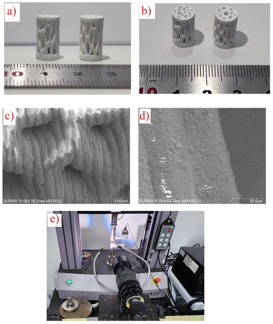
Figure 1.
(a,b) Three-dimensional printed samples after sintering. (c,d) SEM images of samples at different magnifications. (e) Compressive test setup with a microscopic lens.
Printing parameters were fine-tuned based on earlier research [35,36,41], employing a laser power of 100 mW, scanning speed of 5 m/s, hatch spacing of 0.5 mm, and layer thickness of 50 µm. Following the printing process, thermal treatments involving debinding and sintering were applied to eliminate the photosensitive resin and consolidate the HAp scaffolds. The debinding process, carried out at 1050 °C in a muffle furnace, facilitated resin pyrolysis, with the majority of weight loss occurring during this stage, as verified through thermogravimetric analysis [35].
Following the debinding stage, the sintering process was optimized to improve the mechanical characteristics and structural integrity of the hydroxyapatite (HAp) scaffolds while maintaining their crystalline structure. The sintering was performed in air at a carefully regulated temperature of 1250 °C, which was determined to be ideal for enhancing densification and creating strong bonds between particles without compromising HAp’s chemical stability. To avoid structural issues like cracking or warping, the heating rate during sintering was precisely controlled at 5 °C/min, ensuring a gradual temperature increase. The cooling rate was similarly maintained at 5 °C/min to reduce the risk of thermal shock, which could potentially cause microcracks and negatively affect the scaffolds’ mechanical properties. These controlled thermal treatments preserved the intended geometry and porosity of the scaffolds’ lattice structure.
X-ray diffraction (XRD) analysis from previous studies [35,36,41] verified that the optimized sintering parameters successfully maintained the characteristic crystalline peaks of HAp, without any signs of decomposition into tricalcium phosphate (TCP) or other secondary phases. Preserving this phase stability is crucial, as HAp’s bioactivity and mechanical properties are directly related to its crystalline structure. By following these sintering protocols, the resulting scaffolds exhibited a combination of high mechanical performance and biofunctional properties, making them suitable for bone tissue engineering applications.
Figure 1c,d display SEM images of the samples at various magnifications after sintering. The analysis revealed that the layers were well-bonded, with a consistent printing layer thickness of about 50 µm. The sintering process effectively densified the scaffolds, ensuring structural integrity and enhancing mechanical performance.
A high-magnification SEM image (Figure 2) was examined to explore how heat treatment influences the sintering process and particle dimensions of hydroxyapatite (HAp). This image offers a comprehensive view of the scaffold’s microscopic structure, highlighting surface features and particle attributes following the sintering procedure.
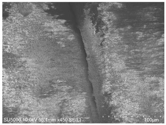
Figure 2.
High-magnification SEM image of the HAp scaffold after sintering, showing well-bonded layers and smooth interparticle connections.
The SEM examination shows well-fused layers with seamless interparticle connections, demonstrating the effectiveness of the sintering process. A minor enlargement in HAp particle size is noted, which is in line with the applied thermal treatment parameters. Importantly, there is no evidence of substantial particle clumping or phase changes, confirming that the sintering conditions successfully promote densification while maintaining HAp’s crystal structure. These observations are consistent with earlier research emphasizing the significance of optimized sintering in enhancing mechanical characteristics and structural integrity [35,36,41].
2.3. Mechanical Testing
Bone scaffolds require an adequate compressive strength. Therefore, compression tests were performed to evaluate the mechanical properties of the two elongated Voronoi scaffolds. The compressive test was repeated ten times for each sample. The compression test was performed using an ETM104B (Shenzhen Wance Testing Machine), as shown in Figure 1e. The results of the compressive tests were plotted as a stress–strain curve. The apparent Young’s modulus (E*), stiffness (S*), and ultimate compressive strength (US) of the scaffolds were calculated from the stress–strain curve using Equation (1) and Equation (2), respectively:
where is the apparent stress of the scaffolds in MPa calculated from Equation (3), is the apparent strain of the scaffolds which is determined using Equation (4), is the applied load in N, and represents the compressive displacement in mm.
where r is the radius of the scaffolds in mm, Li is the initial length of the porous scaffold in mm, Lf is the length of the scaffold after the deformation in mm, and A is the cross-section area in mm2. Based on the concept that stress is constant over the cross-section area and throughout the gauge length.
Energy absorption is an important characteristic in biomedical engineering, particularly for designing scaffolds in the event of a bone crash. Energy absorption was calculated for both homogeneous and gradient scaffolds to compare their ability to absorb energy. It can be obtained from the area under the load–displacement curve using Equation (5) below:
where is the mean crushing force, is the initial crushing distance, and is the final crushing distance.
Because our samples were intended to be employed in the fabrication of biological scaffolds, they needed to be lightweight. As a result, the SEA of the models had to be calculated. SEA is defined as total energy absorbed divided by sample mass. It can be calculated from the following Equation (6):
The microstructures of natural bone are diverse, and the mechanical properties are greatly influenced by porosity of lattice structure. Li et al. [42], recommended that the porosity of lattice structure of the bone scaffold be at least 50% and the pore size be 100–400 µm. In the current study, the gravimetric approach [43] was used to determine porosity of lattice structure as shown in Equation (7):
where is the density of the material, and is the apparent density of the scaffold.
2.4. Digital Image Correlation (DIC) Analysis
Strain distribution during compressive loading of the manufactured hydroxyapatite (HAp) scaffolds was examined using the Digital Image Correlation (DIC) technique. This optical method, which does not require physical contact, allows for comprehensive strain measurement by monitoring the deformation of a speckled pattern applied to the samples’ surfaces. The DIC apparatus consisted of a high-resolution camera (Canon EOS 6D Mark II, 26 MP) positioned at a right angle to the sample, capturing images at set intervals during the loading process. These images were then analyzed using Vic-2D software, version 4.4 (Correlated Solutions, Columbia, SC, USA) to calculate strain fields.
Before testing, the samples were prepared by applying a fine speckle pattern using white and black paints, creating high-contrast features essential for precise DIC analysis. A testing machine (ETM104B, Shenzhen Wance Testing Machine) was used to apply compressive loads to the scaffolds while the camera recorded deformation sequences. The resulting DIC analysis produced strain maps at various stages of loading, revealing areas of stress concentration and the initiation of failure.
3. Results and Discussions
3.1. Mechanical Properties
Figure 3a displays the load–displacement curve of the two samples. It indicates that the homogeneous cylinder is somewhat stiffer than the hollow one. It reveals that the homogeneous cylinder withstood a maximum load of 913.6 N at a displacement of about 0.166 mm with the stiffness of 5162.8 N/mm. Whilst the hollow cylinder reached the highest load of 659.8 N at a displacement of about 0.156 mm with the stiffness of about 3636.3 N/mm. This is attributed to the fact that when homogeneous cylinder is subjected to a load, the load is distributed roughly evenly throughout all portions of the structure, absorbing the most energy, and it can provide a better biological environment for cell proliferation [44].
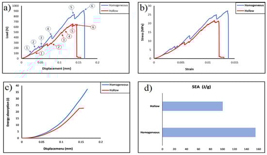
Figure 3.
(a) Load–displacement curve (numbers 1 through 6 represent the same corresponding failure stages in Figure 4); (b) stress–strain curve; (c) energy–displacement curve; (d) the specific energy of the two printed samples.
Figure 3b presents the apparent stress–strain curve of the two designed elongated Voronoi scaffolds. The data show that strain rises with increasing load, and both designs show a linear rise in the apparent stress up to a certain strain value, beyond which the relationship between these two parameters changed to be more moderate. In both structures, there is a linear correlation between apparent stress and strain until they reach a similar apparent strain of approximately 0.003. Nonetheless, the homogeneous structure has an apparent stress of 5.5 MPa which is higher than the apparent stress of the hollow structure of about 3.8 MPa. Then, the apparent stress begins to rise as the strain is increased until both structures reach a maximum deformation and are broken at a strain of 0.014 and 0.013, for the homogeneous structure and for the hollow structure, respectively. It is worth mentioning that these results are higher than those obtained from the samples designed with the standard Voronoi cells, this is due to the fact that cell geometry with a larger pore size can carry a larger amount of stress concentration and loading which leads to an improving the mechanical properties [45]. In addition, the microstructures of the sample could be enhanced through the extension of cell struts [46] and the moderate spacing of the cells from each other. Furthermore, designing a structure with a larger pore size leads to distributing fewer seeds of Voronoi cells [47], where, with the decrease in the number of seed points, the total surface area decreases; hence, the average shear stress of the Voronoi cells’ walls decreases [48].
Table 2 shows the mechanical properties of both designs (homogeneous and hollow cylinder). It can be highlighted that the homogeneous cylinder displayed higher Young’s modulus (1.85 GPa) and ultimate strength (about 27.2 MPa), and the hollow cylinder sample exhibited lower Young’s modulus (1.43 GPa) and ultimate strength 21.7 MPa. It turns out that these results outperformed the results obtained in our previous study for the standard elongated Voronoi structure [40], and they are higher than for the human trabecular bone (0.70–15.0 MPa) [1]. Furthermore, the gained values increased by about 93% when the biopolymer was replaced with the HAp bioceramic material [49]. This is attributed to the HAp’s elevated hardness and excellent compressive strength, and it possesses greater biocompatibility in comparison to the biopolymers [50]. In addition, these values are superior when compared to the work conducted by Abdian et al. [51], where they incorporated HAp into chitosan (CS); and the values are also higher than those of He et al. [52], where they coated scaffolds. Moreover, the improvement in the architectural configuration of the individual Voronoi cell affects the mechanical properties of the Voronoi scaffold [53].
Table 2.
The mechanical properties of the samples.
Figure 3c displays the comparison between energy absorption and displacement for 3D elongated Voronoi scaffolds. It is evident that there is a rising tendency in the relationship between energy and displacement for both samples (homogeneous and hollow). It is noteworthy that the improvements come slowly in the beginning; then, the absorbed energy increases rapidly as the displacement increases, reaching the plateau of about 0.166 mm for homogeneous and 0.149 mm for hollow sample. These findings imply that both structures can benefit from more displacement in order to increase their energy absorption, and this also suggests that the two designs behave similarly as their energy absorption increases. The results indicated that the greater amount of energy was absorbed compared with that absorbed from using the standard elongated Voronoi in our previous work [40]. The total energy absorbed is 69.777 J and 45.254 J for the homogeneous and hollow cylinders, respectively. These results are greater than those obtained in the study for PLA/HAp/YSZ scaffold [54]. Inevitably, changing the pore size could be achieved by adjusting the height characteristics of the structure, which, in turn, leads to the struts of the scaffold becoming thicker and the pore size larger while the number of pores decreases [44], which causes the structure to withstand a higher load per displacement and absorb greater energy. The optimal absorption materials should have a lengthy platform to absorb more energy when crushed [55]. It is noticeable that comparing the two types of designs as illustrated in Figure 3d, the homogeneous cylinder achieved a higher rate of specific energy absorption, as they outperformed the hollow cylinder with the same relative density under a constant loading rate, this is consistent with the results obtained in the previous study [40]. The homogeneous cylinder design features are the best performance with a specific energy absorption of 155.062 J/g. On the contrary, the hollow cylinder achieved a lower performance with a specific energy absorption of about 100.565 J/g. However, this result indicates an overwhelming performance—compared to what was obtained in the previous study [40]—of both cylinders (90%) before making a modification to the Voronoi cell. Additionally, the performance surpasses that reported by Liu et al. in their study on the hierarchical microstructure of bioceramic scaffolds [56].
The 3D porous structures of the scaffolds play an important role in the treatment of bone defects in cases the damage is significant. In such cases, the porosity of the scaffold’s lattice structure during the design phase should closely align with the natural bone’s lattice structure porosity range of 52% to 90%. Additionally, the pore size influences tissue regeneration [57]. It is recommended to design macroporous scaffolding that helps bone growth [58], particularly exceeding 200 µm [59]. Consequently, we designed our scaffolds with approximately 64% and 60% lattice structure porosity for the homogeneous and hollow cylinders, respectively. The lattice structure porosity and the density of the scaffolds were calculated using Equation (7). The density distribution of the scaffolds was regulated by the volume of the structures, which was, in turn, influenced by the number of Voronoi cells. Additionally, both designs were maintained at a consistent volume of about 95 mm3, a density of 0.0005 g/mm3, and a thickness of 0.1 mm.
3.2. Failure Structure
Figure 4 shows the failure of the samples during the compressive loading. The stages numbered from 1 to 6 correspond to specific points on the stress–strain curve shown in Figure 3a, where the discussion of failure mechanisms took place. As shown in Figure 3a and Figure 4, cell failures initiate at low strain. As strain continues to rise, an increasing number of struts fail as they approach their maximum strength. This occurrence leads to heightened fluctuations in the load–displacement curve. With each strut breakage, a sharp decline is observed in the load–displacement curve. Nonetheless, the entire structure remains capable of bearing the load, allowing for load augmentation as displacement increases until reaching point 6 (maximum load). It is worth mentioning that in real applications, these early-stage failures could be harmful to nearby tissue [38].
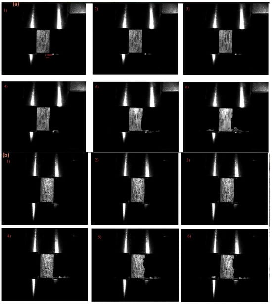
Figure 4.
(a) Failure stages of the homogeneous sample. (b) Failure stages of the hollow sample. The numbers 1–6 refer to points 1–6 on the stress–strain curve in Figure 3.
It can clearly be seen from the load–displacement curve and stress–strain curve at Figure 3a,b that load humps become less sharp and stress valleys become more complanate in the hollow sample. In these printed structures, failure is governed by the fracture of the struts. Due to this, the properties of the parent materials and the quality of the printing could have a direct effect on the failure of the structure. Figure 4 shows that for the homogeneous samples, the failure of the struts starts from the outside surface of the structure, and for the hollow sample, the failure of the sample begins from the inside of the sample. Therefore, identifying the initial failure for hollow samples is difficult.
Figure 5 shows the Digital Image Correlation (DIC) analysis of the homogeneous sample. Initially, as the load is applied, strain is evenly distributed throughout the entire structure. However, as the load continues to increase, the highest strain becomes evident at the junction of the struts, as depicted in Figure 5b. It is from this point that structural failure starts, as illustrated in Figure 5c.
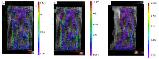
Figure 5.
(a–c) Stages of load distribution through DIC analysis of the von Mises’ strain of the homogeneous sample.
By using the microscopic lens (Figure 6a,b), specific struts that failed during loading were observed. Most of the failure of the lattice initiates at the outer surface of the junction of the struts (shown by red arrow), and then these cracks propagate towards the junction as shown in Figure 6a. Two other failure mechanisms were also observed in the structure. The strength degradation is attributed to the onset of failure at the weakest domain within the structure. This corresponds to the slender struts in the structure (Figure 6b). The critical load in this case corresponds to the maximum bending stress at a strut. Another weak point in the structure is a printing fault. As evident in the last image of Figure 6b, the strut breaks at the printing layer.
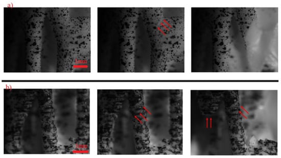
Figure 6.
High magnification image of structures during loading: (a) homogeneous sample; (b) hollow sample.
Figure 7a,b presents the SEM analysis revealing the crack propagation and failure mechanism of the hollow sample at a strain of (0.005). The cracks initiated parallel to the loading direction until reaching the weak bonding interface of the printing layers, which changes its direction and propagates between layers. This observation underscores the significant impact of printing defects in the mechanical properties [35].
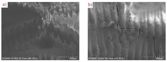
Figure 7.
(a,b): SEM analysis of crack propagation in hollow sample at strain of 0.005.
Despite the mechanical benefits, further refinement is needed to address these failure points and enhance the long-term durability of the scaffolds, highlighting the need for structural improvements to optimize the clinical efficacy of Voronoi-based scaffolds.
4. Conclusions
This research examining two SLA-fabricated HAp Voronoi designs revealed that the uniform cylinder demonstrated enhanced mechanical characteristics, including rigidity, resistance to compression, and specific energy absorption, outperforming traditional Voronoi structures and the human trabecular bone. However, analysis of failure modes uncovered early fractures at strut intersections during stress application, indicating weaknesses in slender struts and printed layers that could potentially damage adjacent tissues. Although the mechanical benefits are evident, additional improvements are necessary to address these weak points and enhance the long-term resilience of the scaffolds. This underscores the importance of structural modifications to maximize the clinical effectiveness of Voronoi-based scaffolds.
Author Contributions
A.A., formal analysis, investigation, methodology, writing—original draft, conceptualization, project administration, validation; Z.D.I.S., formal analysis, methodology, conceptualization, writing—review and editing, project administration, investigation; Z.A., software, visualization, formal analysis, investigation, writing—original draft. C.Z., Writing—review & editing. All authors have read and agreed to the published version of the manuscript.
Funding
This research received no external funding.
Institutional Review Board Statement
Not applicable.
Informed Consent Statement
Not applicable.
Data Availability Statement
The original contributions presented in this study are included in the article. Further inquiries can be directed to the corresponding authors.
Conflicts of Interest
The authors declare that they have no known competing financial interests or personal relationships that could have appeared to influence the work reported in this paper.
Appendix A
Rhinoceros 7 and Grasshopper were employed to generate the homogeneous elongated Voronoi structure (Figure A1). The process began with the creation of a cylindrical form using Circle and Extrude plugins. Random points were then distributed within this cylinder using the Populate 3D Geometry plugin, which were subsequently connected to the 3D Voronoi plugin to create Voronoi cells. To ensure the cells remained within the cylinder’s boundaries, the Solid Intersection plugin was utilized, followed by the Deconstruct Brep plugin for surface extraction and refinement. The Voronoi cells were elongated in the Z-direction using the Scale NU plugin, transforming the standard Voronoi into an elongated version. The final step involved using the Pipe plugin to adjust the thickness of the cell struts, after which the design was baked to produce the completed homogeneous structure.
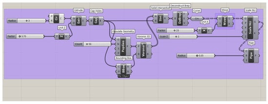
Figure A1.
Grasshopper script for the homogeneous elongated Voronoi structure, showing the use of the Scale NU plugin to elongate Voronoi cells uniformly along the Z-direction with controlled thickness.
The hollow elongated Voronoi structure (Figure A2) was created through a similar process, with additional steps for hollowing the cells. As before, the cylindrical geometry was created and populated with points using the Populate 3D Geometry and 3D Voronoi plugins. A Bounding Box plugin was introduced to aid in aligning the Voronoi structure within the cylinder. The Solid Intersection and Deconstruct Brep plugins were used to confine the cells to the desired volume. The hollowing effect was achieved by applying the Pipe plugin with specific radius parameters. The Scale NU plugin was again employed to elongate the cells in the Z-direction. Both structures maintained consistent volume and density while achieving their respective topological patterns.
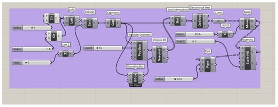
Figure A2.
Grasshopper script for the hollow elongated Voronoi structure, demonstrating the hollowing of cell struts using the Pipe plugin while maintaining Z-direction elongation and consistent volume.
References
- Woodard, J.R.; Hilldore, A.J.; Lan, S.K.; Park, C.J.; Morgan, A.W.; Eurell, J.A.C.; Clark, S.G.; Wheeler, M.B.; Jamison, R.D.; Wagoner Johnson, A.J. The Mechanical Properties and Osteoconductivity of Hydroxyapatite Bone Scaffolds with Multi-Scale Porosity. Biomaterials 2007, 28, 45–54. [Google Scholar] [CrossRef] [PubMed]
- Hutmacher, D.W. Scaffolds In Tissue Engineering Bone and Cartilage. Biomater. Silver Jubil. Compend. 2000, 21, 175–189. [Google Scholar] [CrossRef]
- Bhattacharjee, A.; Bose, S. 3D Printed Hydroxyapatite—Zn2+ Functionalized Starch Composite Bone Grafts for Orthopedic and Dental Applications. Mater. Des. 2022, 221, 110903. [Google Scholar] [CrossRef] [PubMed]
- Wang, Z.; Wang, K.; Lu, X.; Li, M.; Liu, H.; Xie, C.; Meng, F.; Jiang, O.; Li, C.; Zhi, W. BMP-2 Encapsulated Polysaccharide Nanoparticle Modified Biphasic Calcium Phosphate Scaffolds for Bone Tissue Regeneration. J. Biomed. Mater. Res. Part A 2015, 103, 1520–1532. [Google Scholar] [CrossRef]
- Tamo, A.K.; Djouonkep, L.D.W.; Selabi, N.B.S. 3D Printing of Polysa/Ccharide-Based Hydrogel Scaffolds for Tissue Engineering Applications: A Review. Int. J. Biol. Macromol. 2024, 270, 132123. [Google Scholar] [CrossRef]
- Shekhawat, D.; Singh, A.; Banerjee, M.K.; Singh, T.; Patnaik, A. Bioceramic Composites for Orthopaedic Applications: A Comprehensive Review of Mechanical, Biological, and Microstructural Properties. Ceram. Int. 2021, 47, 3013–3030. [Google Scholar] [CrossRef]
- Wang, B.; Arab, A.; Xie, J.; Chen, P. The Influence of Microstructure on the Flexural Properties of 3D Printed Zirconia Part via Digital Light Processing Technology. Materials 2022, 15, 1602. [Google Scholar] [CrossRef]
- Cursaru, L.M.; Iota, M.; Piticescu, R.M.; Tarnita, D.; Savu, S.V.; Savu, I.D.; Dumitrescu, G.; Popescu, D.; Hertzog, R.G.; Calin, M. Hydroxyapatite from Natural Sources for Medical Applications. Materials 2022, 15, 5091. [Google Scholar] [CrossRef]
- Arokiasamy, P.; Abdullah, M.M.A.B.; Abd Rahim, S.Z.; Luhar, S.; Sandu, A.V.; Jamil, N.H.; Nabiałek, M. Synthesis Methods of Hydroxyapatite from Natural Sources: A Review. Ceram. Int. 2022, 48, 14959–14979. [Google Scholar] [CrossRef]
- Kallol, K.M.Z.; Motalab, M.; Parvej, M.S.; Konari, P.R.; Barghouthi, H. Differences of Curing Effects Between a Human and Veterinary Bone Cement. Materials 2019, 12, 470. [Google Scholar] [CrossRef]
- Roseti, L.; Parisi, V.; Petretta, M.; Cavallo, C.; Desando, G.; Bartolotti, I.; Grigolo, B. Scaffolds for Bone Tissue Engineering: State of the Art and New Perspectives. Mater. Sci. Eng. C 2017, 78, 1246–1262. [Google Scholar] [CrossRef] [PubMed]
- Panseri, S.; Cunha, C.; Alessandro, T.D.; Sandri, M.; Russo, A.; Giavaresi, G.; Marcacci, M.; Hung, C.T.; Tampieri, A. Magnetic Hydroxyapatite Bone Substitutes to Enhance Tissue Regeneration: Evaluation In Vitro Using Osteoblast-Like Cells and In Vivo in a Bone Defect. PLoS ONE 2012, 7, 4–11. [Google Scholar] [CrossRef] [PubMed]
- Liu, Z.; Liang, H.; Shi, T.; Xie, D.; Chen, R.; Han, X.; Shen, L.; Wang, C.; Tian, Z. Additive Manufacturing of Hydroxyapatite Bone Scaffolds via Digital Light Processing and In Vitro Compatibility. Ceram. Int. 2019, 45, 11079–11086. [Google Scholar] [CrossRef]
- Lu, F.; Wu, R.; Shen, M.; Xie, L.; Liu, M.; Li, Y.; Xu, S.; Wan, L.; Yang, X.; Gao, C.; et al. Rational Design of Bioceramic Scaffolds with Tuning Pore Geometry by Stereolithography: Microstructure Evaluation and Mechanical Evolution. J. Eur. Ceram. Soc. 2021, 41, 1672–1682. [Google Scholar] [CrossRef]
- Jang, D.W.; Franco, R.A.; Sarkar, S.K.; Lee, B.T. Fabrication of Porous Hydroxyapatite Scaffolds as Artificial Bone Preform and Its Biocompatibility Evaluation. ASAIO J. 2014, 60, 216–223. [Google Scholar] [CrossRef]
- Xu, Y.; Han, G.; Huang, G.; Li, T.; Xia, J.; Guo, D. Properties Evaluations of Topology Optimized Functionally. Materials 2023, 16, 1700. [Google Scholar] [CrossRef]
- Lu, S.; Zhang, M.; Guo, S.; Hur, B.; Yue, X. Numerical Investigation of Impact Behavior of Strut-Based Cellular Structures Designed by Spatial Voronoi Tessellation. Metals 2022, 12, 1189. [Google Scholar] [CrossRef]
- Piros, A.; Trautmann, L. Creating Interior Support Structures with Lightweight Voronoi Scaffold. Int. J. Interact. Des. Manuf. 2023, 17, 93–101. [Google Scholar] [CrossRef]
- George, S.M.; Nayak, C.; Singh, I.; Balani, K. Multifunctional Hydroxyapatite Composites for Orthopedic Applications: A Review. ACS Biomater. Sci. Eng. 2022, 8, 3162–3186. [Google Scholar] [CrossRef]
- Sun, H.; Zou, B.; Wang, X.; Chen, W.; Zhang, G. Advancements in Multi-Material Additive Manufacturing of Advanced Ceramics: A Review of Strategies, Techniques and Equipment. Mater. Chem. Phys. 2024, 319, 129337. [Google Scholar] [CrossRef]
- Cramer, C.L.; Ionescu, E.; Graczyk-zajac, M.; Nelson, A.T.; Katoh, Y.; Haslam, J.J.; Wondraczek, L.; Aguirre, T.G.; Leblanc, S.; Wang, H.; et al. Additive Manufacturing of Ceramic Materials for Energy Applications: Road Map and Opportunities. J. Eur. Ceram. Soc. 2022, 42, 3049–3088. [Google Scholar] [CrossRef]
- Li, Z.; Chu, S.; Wu, Z. A Novel Bio-Inspired Design Method for Porous Structures: Variable-Periodic Voronoi Tessellation. Mater. Des. 2024, 243, 113055. [Google Scholar] [CrossRef]
- Bogala, M.R. Bioprinting Three-Dimensional (3D) Printing of Hydroxyapatite-Based Scaffolds: A Review. Bioprinting 2022, 28, e00244. [Google Scholar] [CrossRef]
- Li, J.; Li, J.; Yang, Y.; He, X.; Wei, X.; Tan, Q.; Wang, Y.; Xu, S. Biocompatibility and Osteointegration Capability of β-TCP Manufactured by Stereolithography 3D Printing: In Vitro Study. Open Life Sci. 2023, 18, 20220530. [Google Scholar] [CrossRef]
- Shao, H.; Zhu, J.; Zhao, X.; Xia, P.; Wang, Y.; Zhang, T.; Gong, Y.; He, Y.; Yao, Q. Additive Manufacturing of Magnesium-Doped Calcium Silicate/Zirconia Ceramic Scaffolds with Projection-Based 3D Printing: Sintering, Mechanical and Biological Behavior. Ceram. Int. 2024, 50, 9280–9292. [Google Scholar] [CrossRef]
- Xu, Z.; Zhang, H.; Yao, B.; Liu, J.; Yang, L.; Shang, J.; Fan, J.; Ouyang, L.; Fan, H.S. Optimizing the Ceramic Slurry Formulation and Process Conditions for DSW Printing. Am. J. Sci. Eng. Technol. 2023, 8, 71–80. [Google Scholar] [CrossRef]
- Zhang, L.; Zeng, Y.; Yao, H.; Shi, Z.; Chen, J. Fabrication and Characterization of ZrO2(3Y)/Al2O3 Micro-Ceramic Gears with High Performance by Vat Photopolymerization 3D Printing. Ceram. Int. 2024, 50, 5187–5197. [Google Scholar] [CrossRef]
- Wu, H.; Liu, W.; Huang, R.; He, R.; Huang, M.; An, D.; Li, H.; Jiang, Q.; Tian, Z.; Ji, X.; et al. Fabrication of High-Performance Al2O3-ZrO2 Composite by a Novel Approach That Integrates Stereolithography-Based 3D Printing and Liquid Precursor in Fi Ltration. Mater. Chem. Phys. 2018, 209, 31–37. [Google Scholar] [CrossRef]
- Ng, W.L.; An, J.; Chua, C.K. Process, Material, and Regulatory Considerations for 3D Printed Medical Devices and Tissue Constructs. Engineering 2024, 36, 146–166. [Google Scholar] [CrossRef]
- Ly, M.; Spinelli, S.; Hays, S.; Zhu, D. 3D Printing of Ceramic Biomaterials. Eng. Regen. 2022, 3, 41–52. [Google Scholar] [CrossRef]
- De Camargo, I.L.; Fortulan, C.A.; Colorado, H.A. A Review on the Ceramic Additive Manufacturing Technologies and Availability of Equipment and Materials. Ceramica 2022, 68, 329–347. [Google Scholar] [CrossRef]
- Bose, S.; Akdogan, E.K.; Balla, V.K.; Ciliveri, S.; Colombo, P.; Franchin, G.; Iu, F.; Franchin, G.; Ku, N.; Kushram, P.; et al. 3D Printing of Ceramics: Advantages, Challenges, Applications, and Perspectives. J. Am. Ceram. Soc. 2024, 107, 7879–7920. [Google Scholar] [CrossRef]
- Prem Ananth, K.; Jayram, N.D. A Comprehensive Review of 3D Printing Techniques for Biomaterial-Based Scaffold Fabrication in Bone Tissue Engineering. Ann. 3D Print. Med. 2024, 13, 100141. [Google Scholar] [CrossRef]
- Dong, D.; Su, H.; Li, X.; Fan, G.; Zhao, D.; Shen, Z.; Liu, Y.; Guo, Y.; Yang, C.; Liu, L.; et al. Microstructures and Mechanical Properties of Biphasic Calcium Phosphate Bioceramics Fabricated by SLA 3D Printing. J. Manuf. Process. 2022, 81, 433–443. [Google Scholar] [CrossRef]
- Chen, Q.; Zou, B.; Lai, Q.; Wang, Y.; Xue, R.; Xing, H. A Study on Biosafety of HAP Ceramic Prepared by SLA-3D Printing Technology Directly. J. Mech. Behav. Biomed. Mater. 2019, 98, 327–335. [Google Scholar] [CrossRef]
- Chen, Q.; Zou, B.; Lai, Q.; Zhao, Y.; Zhu, K. Influence of Irradiation Parameters on the Curing and Interfacial Tensile Strength of HAP Printed Part Fabricated by SLA-3D Printing. J. Eur. Ceram. Soc. 2022, 42, 6721–6732. [Google Scholar] [CrossRef]
- Liu, X.; Zou, B.; Xing, H.; Huang, C. The Preparation of ZrO2-Al2O3 Composite Ceramic by SLA-3D Printing and Sintering Processing. Ceram. Int. 2020, 46, 937–944. [Google Scholar] [CrossRef]
- Kang, J.; Sakthiabirami, K.; Jang, K.; Jang, J.; Oh, G.; Park, C.; Fisher, J.G.; Park, S. Mechanical and Biological Evaluation of Lattice Structured Hydroxyapatite Scaffolds Produced via Stereolithography Additive Manufacturing. Mater. Des. 2022, 214, 110372. [Google Scholar] [CrossRef]
- Liu, R.; Ma, L.; Liu, H.; Xu, B.; Feng, C.; He, R. Effects of Pore Size on the Mechanical and Biological Properties of Stereolithographic 3D Printed HAp Bioceramic Scaffold. Ceram. Int. 2021, 47, 28924–28931. [Google Scholar] [CrossRef]
- Alknery, Z.; Sktani, Z.D.I.; Arab, A. Effect of Cell Geometry on the Mechanical Properties of 3D Voronoi Tessellation. J. Funct. Biomater. 2022, 13, 302. [Google Scholar] [CrossRef]
- Chen, Q.; Zou, B.; Lai, Q.; Wang, Y.; Zhu, K.; Deng, Y.; Huang, C. 3D Printing and Osteogenesis of Loofah-Like Hydroxyapatite Bone Scaffolds. Ceram. Int. 2021, 47, 20352–20361. [Google Scholar] [CrossRef]
- Li, G.; Wang, L.; Pan, W.; Yang, F.; Jiang, W.; Wu, X. In Vitro and In Vivo Study of Additive Manufactured Porous Ti6Al4V Scaffolds for Repairing Bone Defects. Sci. Rep. 2016, 6, 34072. [Google Scholar] [CrossRef] [PubMed]
- Guarino, V.; Causa, F.; Taddei, P.; di Foggia, M.; Ciapetti, G.; Martini, D.; Fagnano, C.; Baldini, N.; Ambrosio, L. Polylactic Acid Fibre-Reinforced Polycaprolactone Scaffolds for Bone Tissue Engineering. Biomaterials 2008, 29, 3662–3670. [Google Scholar] [CrossRef]
- Zhang, J.; Chen, X.; Sun, Y.; Yang, J.; Chen, R.; Xiong, Y.; Hou, W.; Bai, L. Design of a Biomimetic Graded TPMS Scaffold with Quantitatively Adjustable Pore Size. Mater. Des. 2022, 218, 110665. [Google Scholar] [CrossRef]
- Chao, L.; Jiao, C.; Liang, H.; Xie, D.; Shen, L.; Liu, Z. Analysis of Mechanical Properties and Permeability of Trabecular-Like Porous Scaffold by Additive Manufacturing. Front. Bioeng. Biotechnol. 2021, 9, 779854. [Google Scholar] [CrossRef]
- van Nuland, T.F.; van Dommelen, J.A.; Geers, M.G.D. An Anisotropic Voronoi Algorithm for Generating Polycrystalline Microstructures with Preferred Growth Directions. Comput. Mater. Sci. 2021, 186, 109947. [Google Scholar] [CrossRef]
- Li, J.; Guo, D.; Li, J.; Wei, X.; Sun, Z.; Yang, B.; Lu, T.; Ouyang, P.; Chang, S.; Liu, W.; et al. Irregular Pore Size of Degradable Bioceramic Voronoi Scaffolds Prepared by Stereolithography: Osteogenesis and Computational Fluid Dynamics Analysis. Mater. Des. 2022, 224, 111414. [Google Scholar] [CrossRef]
- Paz, C.; Suárez, E.; Gil, C.; Parga, O. Numerical Modelling of Osteocyte Growth on Different Bone Tissue Scaffolds. Comput. Methods Biomech. Biomed. Engin. 2022, 25, 641–655. [Google Scholar] [CrossRef]
- Boodaghi, R.; Akkurt, I.; Boodaghi, P. Investigation and ANN-Based Prediction of the Radiation Shielding, Structural and Mechanical Properties of the Hydroxyapatite (HAP) Bio-Composite as Artificial Bone. Radiat. Phys. Chem. 2022, 197, 110208. [Google Scholar] [CrossRef]
- Adamu, M.A.; Sumaila, M.; Dauda, M.; Ause, T. Production and Optimization of Novel Rice Husk Ash Reinforced Polycaprolactone/Hydroxyapatite Composite for Bone Regeneration Using Grey Relational Analysis. Sci. Afr. 2023, 19, e01563. [Google Scholar] [CrossRef]
- Abdian, N.; Etminanfar, M.; Omid, S.; Sheykholeslami, R.; Hamishehkar, H.; Khalil-allafi, J. Preparation and Characterization of Chitosan/Hydroxyapatite Scaffolds Containing Mesoporous SiO2-HA for Drug Delivery Applications. Mater. Chem. Phys. 2023, 301, 127672. [Google Scholar] [CrossRef]
- He, Z.; Jiao, C.; Wu, J.; Gu, J.; Liang, H. Zn-Doped Chitosan/Alginate Multilayer Coatings on Porous Hydroxyapatite Scaffold with Osteogenic and Antibacterial Properties. Int. J. Bioprinting 2023, 9, 668. [Google Scholar] [CrossRef] [PubMed]
- Wang, X.; Xu, S.; Zhou, S.; Xu, W.; Leary, M.; Choong, P.; Qian, M.; Brandt, M.; Min, Y. Topological Design and Additive Manufacturing of Porous Metals for Bone Scaffolds and Orthopaedic Implants: A Review. Biomaterials 2016, 83, 127–141. [Google Scholar] [CrossRef] [PubMed]
- Ziaee, F.; Zebarjad, S.M.; Javadpour, S. Compressive and Flexural Properties of Novel Polylactic Acid/Hydroxyapatite/Yttria-Stabilized Zirconia Hybrid Nanocomposite Scaffold. Int. J. Polym. Mater. Polym. Biomater. 2018, 67, 229–238. [Google Scholar] [CrossRef]
- Zhang, L.; Feih, S.; Daynes, S.; Chang, S.; Yu, M.; Wei, J.; Feng, W. Energy Absorption Characteristics of Metallic Triply Periodic Minimal Surface Sheet Structures Under Compressive Loading. Addit. Manuf. 2018, 23, 505–515. [Google Scholar] [CrossRef]
- Liu, Q.; Li, T.; Wah, S.; Yee, S.; Chiuan, C.; Zhai, W. Controlling the Hierarchical Microstructure of Bioceramic Scaffolds by 3D Printing of Emulsion Inks. Addit. Manuf. 2023, 61, 103332. [Google Scholar] [CrossRef]
- Yu, Y.; Orlov, E.D.; Klimashina, E.S.; Evdokimov, P.V.; Safronova, T. V Colloidal Forming of Macroporous Calcium Pyrophosphate Bioceramics in 3D-Printed Molds. Bioact. Mater. 2020, 5, 309–317. [Google Scholar] [CrossRef]
- Wang, W.; Yeung, K.W.K. Bone Grafts and Biomaterials Substitutes for Bone Defect Repair: A Review. Bioact. Mater. 2017, 2, 224–247. [Google Scholar] [CrossRef]
- Choi, S.W.; Zhang, Y.; MacEwan, M.R.; Xia, Y. Neovascularization in Biodegradable Inverse Opal Scaffolds with Uniform and Precisely Controlled Pore Sizes. Adv. Healthc. Mater. 2014, 2, 145–154. [Google Scholar] [CrossRef]
Disclaimer/Publisher’s Note: The statements, opinions and data contained in all publications are solely those of the individual author(s) and contributor(s) and not of MDPI and/or the editor(s). MDPI and/or the editor(s) disclaim responsibility for any injury to people or property resulting from any ideas, methods, instructions or products referred to in the content. |
© 2025 by the authors. Licensee MDPI, Basel, Switzerland. This article is an open access article distributed under the terms and conditions of the Creative Commons Attribution (CC BY) license (https://creativecommons.org/licenses/by/4.0/).