Article

Hot Corrosion Behavior of Plasma-Sprayed Gd2Zr2O7/YSZ Functionally Graded Thermal Barrier Coatings

by
Rajasekaramoorthy Manogaran
1,2,
Karthikeyan Alagu
1,*,
Anderson Arul
1,
Anandh Jesuraj
2,
Dinesh Kumar Devarajan
2,
Govindhasamy Murugadoss
2 and
Kamalan Kirubaharan Amirtharaj Mosas
3,*
1
School of Mechanical Engineering, Sathyabama Institute of Science and Technology, Chennai 600119, India
2
Centre for Nanoscience and Nanotechnology, Sathyabama Institute of Science and Technology, Chennai 600119, India
3
Coating Department, FunGlass—Centre for Functional and Surface Functionalised Glass, Alexander Dubcek University of Trencin, 91150 Trencin, Slovakia
*
Authors to whom correspondence should be addressed.
Ceramics 2024, 7(2), 579-595; https://doi.org/10.3390/ceramics7020038
Submission received: 22 March 2024 / Revised: 18 April 2024 / Accepted: 27 April 2024 / Published: 29 April 2024
(This article belongs to the Special Issue Research Progress in Ceramic Coatings)

Abstract

:
The development of advanced thermal barrier coating (TBC) materials with better hot corrosion resistance, phase stability, and residual stresses is an emerging research area in the aerospace industry. In the present study, four kinds of TBCs, namely, single-layer yttria-stabilized zirconia (YSZ), single-layer gadolinium zirconate (GZ), bilayer gadolinium zirconate/yttria-stabilized zirconia (YSZ/GZ), and a multilayer functionally graded coating (FGC) of YSZ and GZ, were deposited on NiCrAlY bond-coated nickel-based superalloy (Inconel 718) substrates using the atmospheric plasma spray technique. The hot corrosion behavior of the coatings was tested by applying a mixture of Na2SO4 and V2O5 onto the surface of TBC, followed by isothermal heat treatment at 1273 K for 50 h. The characterization of the corroded samples was performed by X-ray diffraction (XRD), scanning electron microscopy (SEM), and energy dispersive spectroscopy (EDS) to identify physical and chemical changes in the coatings. GIXRD was used to analyze the residual stresses of the coatings. Residual stress in the FGC coating was found to be −15.2 ± 10.6 MPa. The wear resistance of TBCs is studied using a linear reciprocating tribometer, and the results indicate that gadolinium zirconate-based TBCs showed better performance when deposited in bilayer and multilayered functionally graded TBC systems. The wear rate of as-coated FGC coatings was determined to be 2.90 × 10⁻⁴ mm3/Nm, which is lower than the conventional YSZ coating.

1. Introduction

Thermal barrier coatings (TBCs) for gas turbine engine components have the potential advantage of increasing operating temperature and thereby improving efficiency [1]. The main function of the TBC system is to protect turbine components from extremely harmful hot gaseous environments such as oxidation and hot corrosion. For example, 7–8 wt.% yttria-stabilized zirconia (YSZ) is commonly used as a conventional ceramic topcoat material that provides excellent performance up to 1473 K for prolonged durations. When used at temperatures above 1473 K, it has unfavorable phase change, sintering, and poor hot corrosion. The demand for increasing operating temperatures and efficiency must be met in order to find a suitable alternative TBC material for ceramic topcoats. High-entropy rare-earth zirconates are a class of advanced ceramic materials that are composed of multiple elements in nearly equimolar ratios, which results in a high degree of configurational entropy. Gadolinium zirconate (Gd2Zr2O7) is not typically classified as a high-entropy rare-earth zirconate. However, gadolinium zirconate does belong to the family of rare-earth zirconates and shares some similarities with high-entropy materials in terms of its structure and properties. Gadolinium zirconate (GZ) is one of the most promising materials considered for replacing the conventionally used YSZ in TBC because of its lower thermal conductivity (0.7–1.1 W m−1K−1 than YSZ (1.1–1.8 W m−1K−1), comparable thermal expansion coefficient (~10.5 ×10⁻⁶ K−1) to YSZ (~11 ×10−6 K−1), high phase stability (up to 1823 K), lower sinterability, better chemical resistance, etc. [2,3]. However, single-layer GZ TBCs do not have improved performance compared with YSZ because of their poor chemical inertness to the TGO layer and lower mechanical properties than that of YSZ, such as hardness, wear resistance, and fracture toughness [4]. Therefore, bilayered YSZ/GZ TBC has been introduced as a potential TBC to improve the mechanical properties and avoid chemical incompatibility with the TGO layer. Numerous studies have reported that bilayered YSZ/GZ performed better than single-layer YSZ and single-layer GZ [5,6,7,8,9,10,11,12]. Few studies [13,14,15,16,17,18,19,20,21] have supported the idea that the development of functionally graded coatings can improve lifetime performance. Here, gradual compositional variation along the thickness of the coating was achieved by feeding both YSZ and GZ using an independent spray gun and feeder. It is understood that the authors controlled the flow of YSZ and GZ to obtain graded regions. The YSZ composition was 100% on top of the bond coat, and the subsequent layer composition of GZ was increased. Eventually, the top layer consisted of 100 percent GZ. Previously, this was achieved by using multiple plasma spray guns preloaded with feedstocks such as YSZ and GZ. In this way, FGC is developed by gradually varying the flow of the feedstocks, which requires complex programming. It is more efficient and cost-effective to prepare composite powders of a desirable ratio when synthesized using solid-state reaction and deposited conventionally. When industrial gas turbine engines are operated in a high-corrosion environment with low-quality fuel containing impurities such as Na, V, and S, the formation of Na2SO4 and V2O5 salt on TBC-coated turbine engine components can occur. Such impurities react with the surface of the topcoat and cause chemical and mechanical degradation, followed by failure of the coatings. Habibi et al. [22] examined the hot corrosion performance of Gd2Zr2O7, YSZ, and YSZ + Gd2Zr2O7 composite coatings at 1050 °C in the presence of a molten mixture of Na2SO4 + V2O5. The authors concluded that the Gd2Zr2O7 + YSZ composite coating was more stable than YSZ. This was attributed to the delayed formation of YVO4 crystals, which was caused by the major consumption of V2O5 during the formation of GdVO4. Additionally, there was a reduction in the formation of monoclinic ZrO2 and YVO4 crystals. Hossein et al. [23] reported that the chemical reaction between a corrosive salt and a YSZ ceramic topcoat produced YVO4, where yttria leached from YSZ and caused a phase transformation from stable prime tetragonal to monoclinic followed by detrimental failure of the coatings. Anandh et al. [8] investigated the hot corrosive behavior of single-layer YSZ and bilayer YSZ/GZ TBCs using EB-PVD (Plassys MEB 600). They reported that GdVO4 was found as a result of a chemical reaction between GZ and a hot corrosive mixture and showed improved hot corrosion resistance performance compared with YSZ coatings.
Mahade et al. [24] developed composite GZ and YSZ coatings using the suspension plasma spray coating technique and studied the hot corrosion behavior. The results revealed that the composite of GZ and YSZ coatings showed improved hot corrosion performance compared with GZ coatings. However, the suspension plasma spray technique is much more complex, and the preparation of feedstock in suspension form increases the production duration significantly compared with the APS process. As mentioned earlier, YSZ has superior mechanical properties, such as fracture toughness, hardness, and wear resistance, compared with GZ. Although wear resistance is not an issue in gas turbine industries, studying the wear resistance of the coating using a simple wear test, such as a pin-on-disc or linear reciprocating tribometer, can be highly efficient in understanding the coating’s wear behavior and associated mechanical properties.
Wang et al. [25] reported the tribological properties of plasma-sprayed YSZ-PTFE composite coatings and revealed that the composite coatings showed a lower coefficient of friction and lower wear rate than conventional plasma-sprayed coatings. A few more studies [26,27] have found improvements in tribological behavior, where composite coatings were developed with YSZ and suitable materials such as Al2O3, SiC, etc., and the results revealed improved wear resistance and a lower coefficient of friction. However, there are very limited studies on the tribological behavior of functionally graded coatings under various environmental conditions, such as RT and high temperatures.
The present work aims to investigate a suitable TBC architecture to provide durable and high-performance TBCs for industrial/aerospace gas turbine engine applications. Here, 33 wt.% GZ/67 wt.% YSZ and 67 wt.% GZ/33 wt.% YSZ composite ceramic powders were synthesized using a solid-state reaction with the help of a high-velocity ball mill. Prior to improving the mechanical properties and retaining the physical and chemical properties of GZ, bilayer and functionally graded coatings were developed using the plasma spray coating technique. The mechanical and hot corrosion behaviors of functionally graded YSZ/GZ coatings were investigated and compared with those of single-layer YSZ, GZ, and bilayer YSZ/GZ TBCs. The structural and microstructural behaviors of the samples exposed to hot corrosion were investigated.

2. Materials and Methods

2.1. Substrate Preparation

The substrate used for wear testing was a 15 mm × 15 mm × 5 mm nickel-based superalloy (Inconel 718). For the hot corrosion test, a 20 mm diameter and 5 mm thickness substrate was used. Both substrates were cut using wire-cut electrical discharge machining (EDM). To produce a uniform coating, Inconel 718 substrates were metallographically ground and polished by various silicon carbide emery sheets. Before applying the bond coat, the substrates were prepared by sandblasting them using alumina particles (16 mesh). This process was performed to enhance the adhesion of the metallic bond coating material to the surface of the substrate.

2.2. Development of TBC by the APS Technique

NiCrAlY, Amdry 962 (Oerlikon Metco, Aargau, Switzerland) (Figure 1a) metallic bond coat powder (21.33Cr-10.50Al-1.05Y-bal. Ni) with a particle size of 40–60 µm was deposited using APS by feeding the powder into plasma and depositing it on the substrate. The APS processing parameters are given in Table 1. The plasma spray gun (Metco 3MB) (Oerlikon Metco, Aargau, Switzerland) was operated at a high power of 40 kW. The arc current and arc voltage were ~500 amps and 70 volts, respectively. Argon gas was used as the primary gas with a flow rate of 80–90 LPM, and hydrogen was used as the secondary gas with a flow rate of 15–18 LPM [28]. The distance between the substrate and nozzle was kept at approximately 80 mm. The obtained coating thickness of the bond coat was ~80 µm to 100 µm.
YSZ (Oerlikon Metco, Switzerland) (Figure 1b) was deposited onto the bond coat to a thickness of ~230 µm. Similarly, a single-layer GZ (Shanghai Xinglu Chemical Technology, Shanghai) (Figure 1c) coating was produced by depositing ~230 µm of GZ on the bond-coated substrate. In the YSZ/GZ bilayer coating, YSZ was deposited as an intermediate layer with a coating thickness of ~120 µm, whereas GZ was deposited on top of YSZ to a thickness of ~120 µm.
For the functionally graded coating (FGC), ~60 µm thick YSZ was deposited on top of the bond coat. Then, 33 wt.% GZ/67 wt.% YSZ composite, followed by 67 wt.% GZ/33 wt.% YSZ composite coating, was deposited. Finally, a dense GZ layer of ~60–75 µm thickness was deposited on top of the 67 wt.% GZ/33 wt.% YSZ composite coating.

2.3. Characterization

X-ray diffraction analysis was performed using an X’Pert Pro MRD XRD system (M/s Panalytical, Overijssel, The Netherlands) with Cu Kα (1.5406 Å) radiation generated at 40 kV and 30 mA to study the hot corrosion-tested samples to determine crystal structure and phase changes. The scan was performed over the 2θ range of 20° to 90° at a scan rate of 3° per min. A Thermo Scientific Apreo S (Thermo Fisher Scientific, Waltham, MA, USA) high-resolution scanning electron microscope coupled with an energy-dispersive spectrometer (EDS) was used to analyze the microstructure and complete elemental analysis. YSZ, GZ powder feedstocks, and coated samples were sputter-coated with a thin layer of gold–palladium for analysis by FE-SEM to reduce the charging effect.

2.4. Hot Corrosion Test

A corrosion test was performed on the TBC-coated samples of 20 mm in diameter, where 55 wt.% vanadium pentoxide (V2O5) and 45 wt.% sodium sulfate (Na2SO4) mixtures were used as a corrosive medium to accelerate the corrosion reaction. These corrosive molten mixtures chemically interact with the topcoat material, causing degradation of the coatings. Prior to depositing the corrosive mixtures, V2O5 and Na2SO4 were dispersed in distilled water, followed by the application of approximately 4 mg/cm2 in the form of paste on the surface of the center of the disc within 3 mm of the edges to avoid edge failure [24]. Several studies have carried out hot corrosion tests at 1223 K [29,30]; however, in this work, the test was conducted at 1273 K using a programmable muffle furnace for 50 h.

2.5. Residual Stress Measurement

A “d vs. sin2ψ” method was used to evaluate the stress in the coatings, where “d” is the lattice spacing in the polycrystalline material and “ψ” is the angle of incidence of the (hkl) plane of the materials with different grain orientations. Parallel beam geometry that comprises an X-ray lens in the incident beam and a parallel plate collimator in the diffracted beam has been employed in the XRD system compared with classical Bragg–Brenteno geometry, which allows for stress measurements without any height or measurement errors associated with low angle peaks.
The analysis was carried out in an X’Pert Pro MRD XRD system (M/s Panalytical, The Netherlands) employing Cu Kα radiation with a wavelength of 1.5406 Å, a target power of 45 kV and 40 mA, and a scanning speed of 0.01°/s. The slope obtained from the linear fit of the “d vs. sin2ψ” plot indicates the residual stresses present in the coatings. The values of E and ν for YSZ are 228 GPa and 0.20, respectively. Similarly, for GZ, the values are 175 and 0.23 [31,32]. The residual stress values obtained in the coatings at different peaks were identified during XRD analysis.

2.6. Vickers Hardness Test

The hardness of the TBCs was tested using a Shimadzu HMV-G Series micro Vicker hardness tester. A diamond tip indenter was used to produce plastic deformation of the surface of the TBCs. The hardness of the material was derived from the indentation caused by the diamond tip corresponding to the load applied. The hardness test was conducted with a 100 g load. The hardness value HV0.1 was derived from the mean of five indentations. The hardness of the as-coated TBCs and a set of TBCs heat-treated at 1273 K were determined and analyzed [33].

2.7. Tribology Studies

A wear test was carried out under dry sliding conditions at room temperature (300 K) and 673 K with a relative humidity of approximately 40% using a linear reciprocating tribometer (Ducom Instruments, Bangalore, India). The friction curves were obtained as a function of sliding distance at a sliding velocity of 3 cm/s and an applied load of 5 N. An Al2O3 ball with a diameter of 6 mm was used as a sliding counter body. A contact stylus profilometer (DektakXT, Bruker, Billerica, MA, USA) was used to obtain the wear profile of the samples after the friction test.

3. Results and Discussion

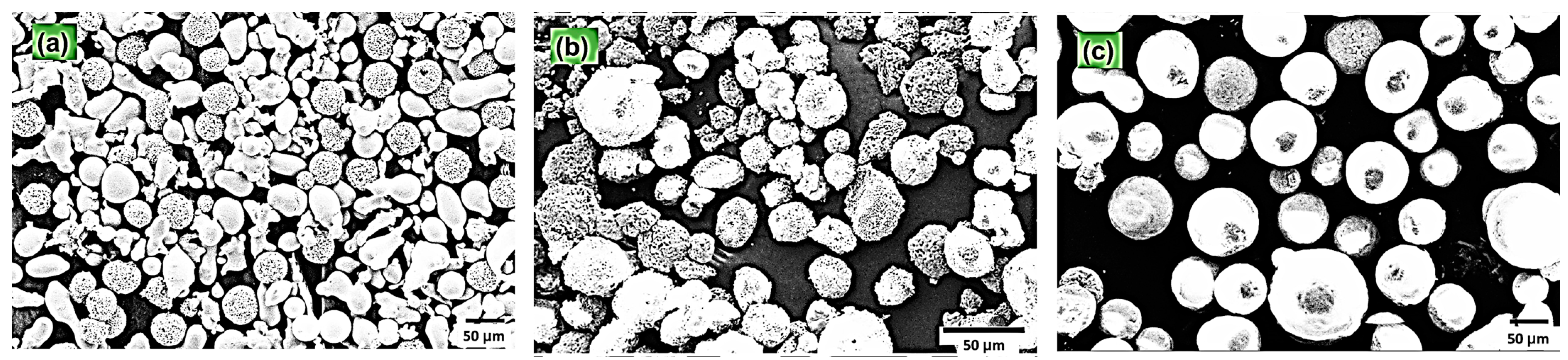
3.1. SEM Analysis of Powder Feedstock

SEM images of the powder feedstock used for developing TBC using APS are shown in Figure 2. YSZ and GZ powder feedstocks were sputter-coated with a thin layer of gold–palladium for analysis by FE-SEM, while NiCrAlY did not require such a conductive coating for SEM analysis. In Figure 2a, the SEM image of the NiCrAlY metallic bond coat material shows a powder with a wide range of particle sizes, ranging from submicron to several microns (10 μm to 100 μm). The particles are generally irregular in shape, with some sharp edges and corners. The surface of the particles is rough and textured, with a number of small pores and defects. In Figure 2b, the SEM image of the YSZ powder shows a powder with a more uniform particle size (10 μm to 100 μm) than the NiCrAlY powder. The particles are generally spherical in shape, with a smooth surface texture. The particles are also relatively dense, with few pores and defects. In Figure 2c, the SEM image of the GZ powder shows a powder with a particle size (40 μm to 100 μm) distribution similar to that of the YSZ powder. The particles are also generally spherical in shape, with a smooth surface texture. However, the YSZ particles are slightly less dense than the GZ particles, with a few more pores and defects. The average particle size of all three feedstock powders can be observed to be in the range of 40 μm to 60 μm, which is suitable for plasma spray coating processes.
Overall, the SEM images of the NiCrAlY, YSZ, and GZ powders show that the powders have different particle sizes, shapes, and surface textures. The NiCrAlY powder has a wide range of particle sizes and a rough surface texture, while the YSZ and GZ powders have a more uniform particle size and a smooth surface texture.

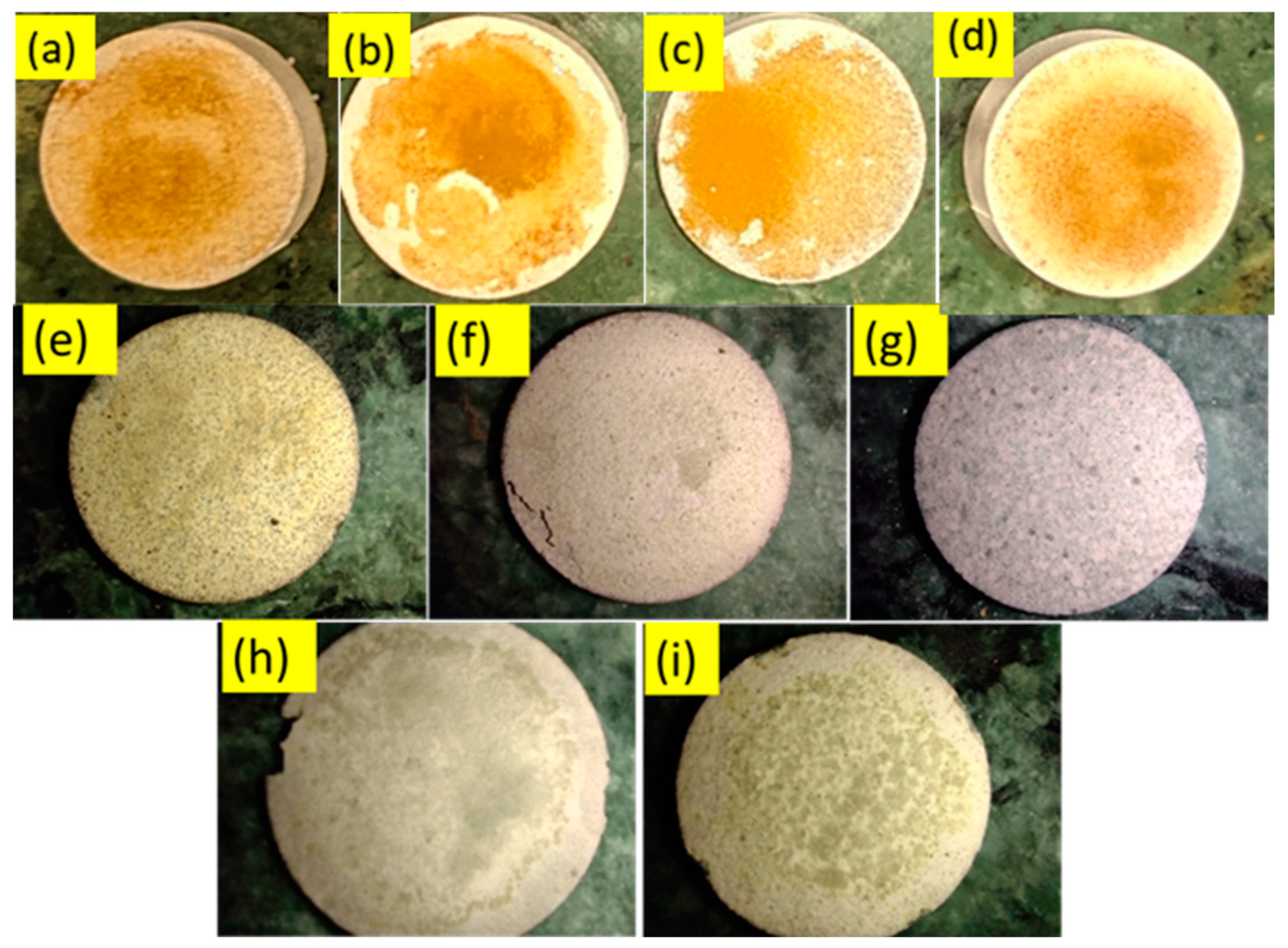
3.2. Hot Corrosion Test

The TBC-coated samples with applied corrosive salt paste shown in Figure 3a–d were heated at 1273 K for 5 h and inspected for failure of the coating. This process was repeated for a total of 50 h. Figure 3e–i show the TBCs after the test. YSZ/GZ bilayer coating spallation occurred after 15 h, and complete failure occurred after 30 h. Figure 3g shows the YSZ/GZ bilayer coating after the test, where the top layer is completely peeled off. After 40 h, GZ developed cracks, while YSZ and FGC did not develop any physical damage because of hot corrosion, although the corrosion of the surface was significant and visible to the naked eye. The structural and elemental analysis of the coating was performed using XRD, SEM, and EDS.

3.2.1. Structural Analysis

This undesirable phase transformation causes volumetric expansion, resulting in the failure of the coatings. Bilayer and functionally graded coatings of GZ have a cubic phase (JCPDS card no. 80-0469) structure. Generally, rare-earth zirconates of the A2B2O7 compound can form either defective fluorite or pyrochlore structures. The pyrochlore structure occurs when the cation and oxygen vacancies occupy precise positions in the cubic crystal structure, whereas the defect fluorite structure occurs because of the random position of cation and oxygen vacancies [34]. However, the thermal conductivities of the defect fluorite and pyrochlore crystal structures are very similar. According to this study, the crystal structure of fluorite or pyrochlore is based on temperature. If the materials are treated at temperatures from 973 K to 1473 K, the structure corresponds to the defective fluorite structure. If the material is heat treated at temperatures from 1300 K to 1400 K, the obtained crystal structure can be a pyrochlore structure. The pyrochlore crystal structure has 2θ peak positions of 14.54°, 23.90°, and 37.22°, which are not observed in Figure 4 and Figure 5. Thus, this confirms the formation of a defect fluorite structure in bilayered and functionally graded GZ coatings. The cubic phase in GZ provides better phase stability and exhibits no volumetric phase transformation up to 1823 K. The lattice parameters of the YSZ and GZ coatings are calculated and found to be a = 3.626 Å and c = 5.151 Å for YSZ and a = 10.564 Å, a = 10.555 Å, and a = 10.507 Å for GZ and GZ layers in the YSZ/GZ bilayer and FGCs, respectively. The calculated lattice parameter value for GZ in FGC is in close agreement with the standard JCPDS value a = 10.52 Å, which reveals the formation of a more stress-free coating than single-layer GZ and YSZ/GZ bilayers [35]. Obtaining a stress-free coating is a greater advantage of the use of the FGC design.

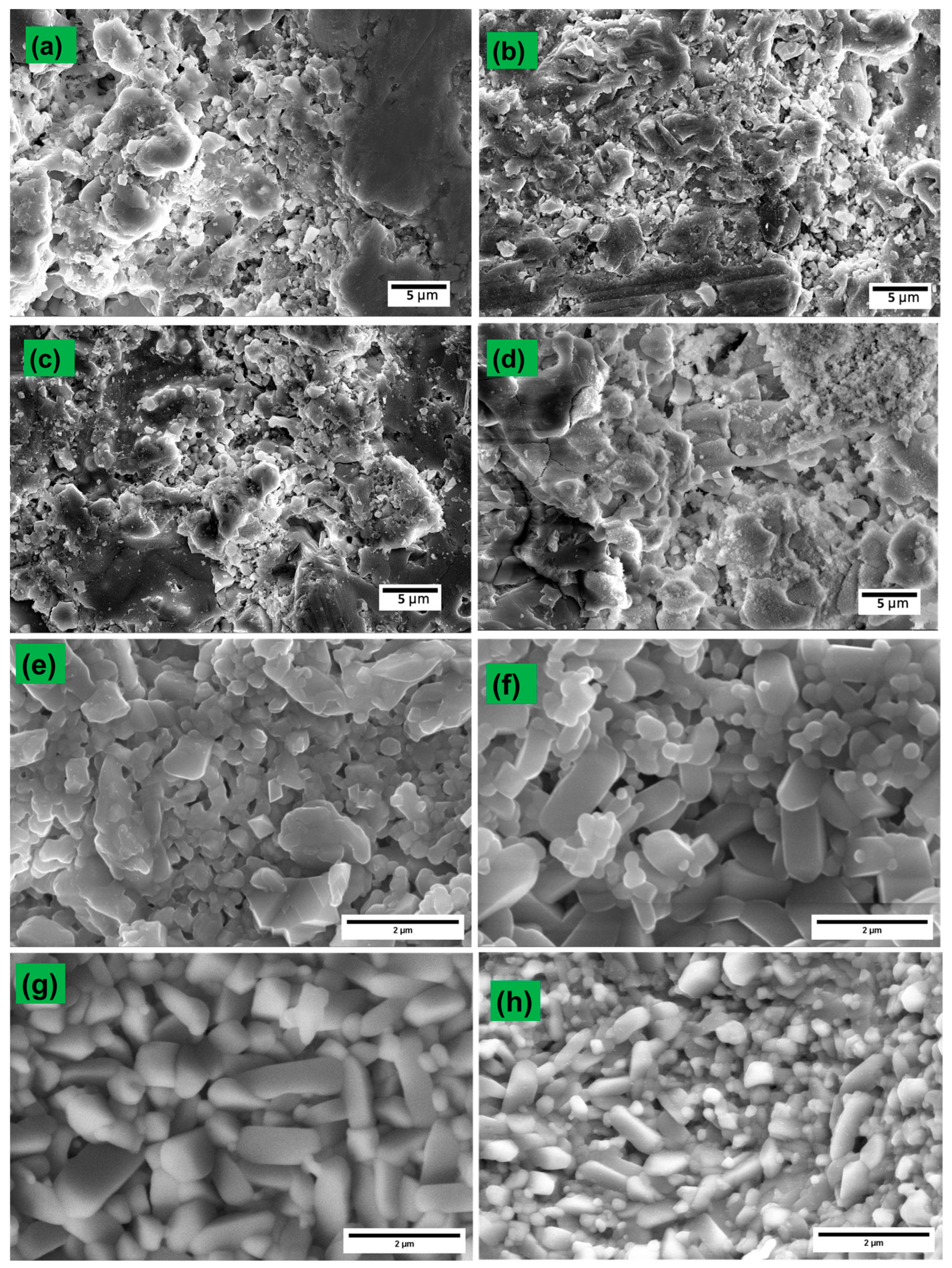
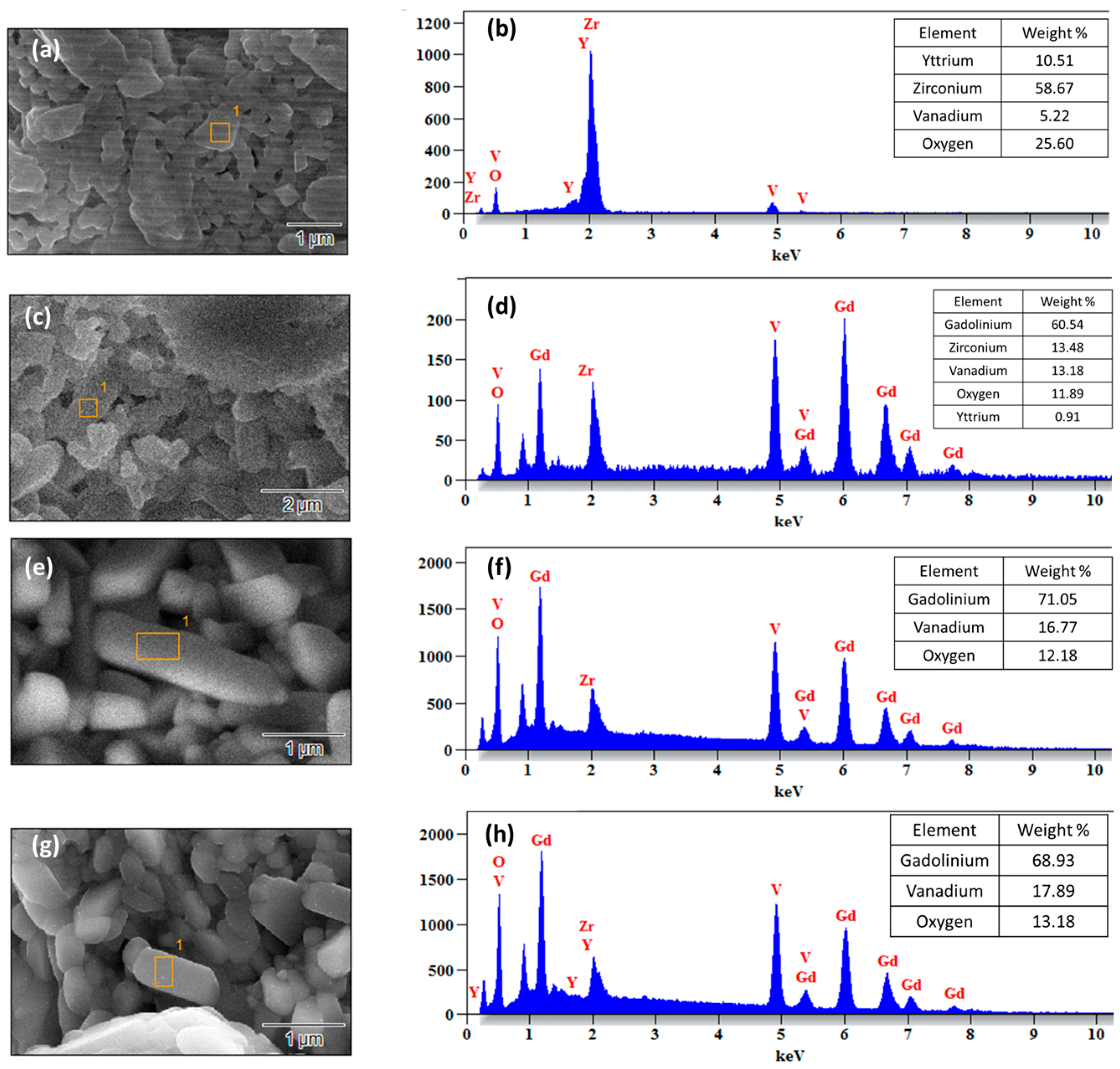
3.2.2. Microstructure and Elemental Analysis

Figure 6a–d show the HR SEM micrographs of the surface for the as-coated TBCs. The surface morphology of the TBCs resembles the typical morphology of plasma-sprayed coatings [34,36]. The salt paste applied onto the TBC melts and flows on the surface of the TBC. Molten salt reacts with the topcoat material of the TBC and produces the resultant product. Figure 6 and Figure 7 show a high-magnification HR SEM micrograph of the surface of the TBCs after the hot corrosion test and the EDS spectrum of the selected area on the surface of the TBC. In the case of the YSZ coating, YVO4 is formed, which was confirmed by the EDS spectrum shown in Figure 7b along with its high magnification SEM image, as shown in Figure 6e and Figure 7a. Here, yttria from YSZ is leached out, and monoclinic ZrO2 is formed, which is not as stable as YSZ and is also accompanied by a volume change.
Since the percentage of yttria in YSZ is very small, the reaction is quite detrimental. Generally, molten salts react on the surface and further flow through microcavities in the TBC and penetrate deeper into the TBC until they reach the underlying alloy. In the case of GZ, GdVO4 is formed after the reaction of the TBC with the molten salt. Equation (1) shows the chemical reaction that occurs between Na2SO4 + V2O5 at high temperatures as follows:
V2O5 + Na2SO4 → 2(NaVO3) + SO3
Equation (2) shows the reaction between NaVO3 and YSZ on the surface of the coating at high temperatures, where monoclinic ZrO2 and YVO4 are produced as follows:
ZrO2-Y2O3 + 2(NaVO3) → ZrO2 + 2(YVO4) + Na2O
Similarly, in cases of GZ top-coated TBCs, the following chemical reaction occurs, as shown in Equation (3), where GdVO4 is formed [22]:
Gd2Zr2O7 + 2NaVO3 → 2GdVO4 + 2ZrO2 + Na2O
GdVO4 is much more stable than YVO4, and it forms a dense layer above the TBC, preventing further reactions on the surface. Additionally, the percentage of gadolinium in GZ is very high, and the formation of GdVO4 does not affect the overall composition of GZ. However, sometimes, when the protective layer is formed, which does not allow for a further reaction, the molten salts flow through the microcavities forcibly, which results in instant degradation of TBC [37], while the usual reaction with molten salt occurs on the surface of the TBC, where small amounts of materials are leached to the surface and resultant products are obtained.
EDS spectra were recorded for all the TBC samples after the hot corrosion test. The composition of the product formed after the Na2SO4 and V2O5 molten salt hot corrosion test can be identified and confirmed from the EDS spectrum and X-ray diffraction pattern. EDS was recorded on the resultant products formed during and after the reaction marked in the rectangles in the HR SEM micrographs, and their elemental compositions were identified, which conformed with the findings from XRD analysis [38].

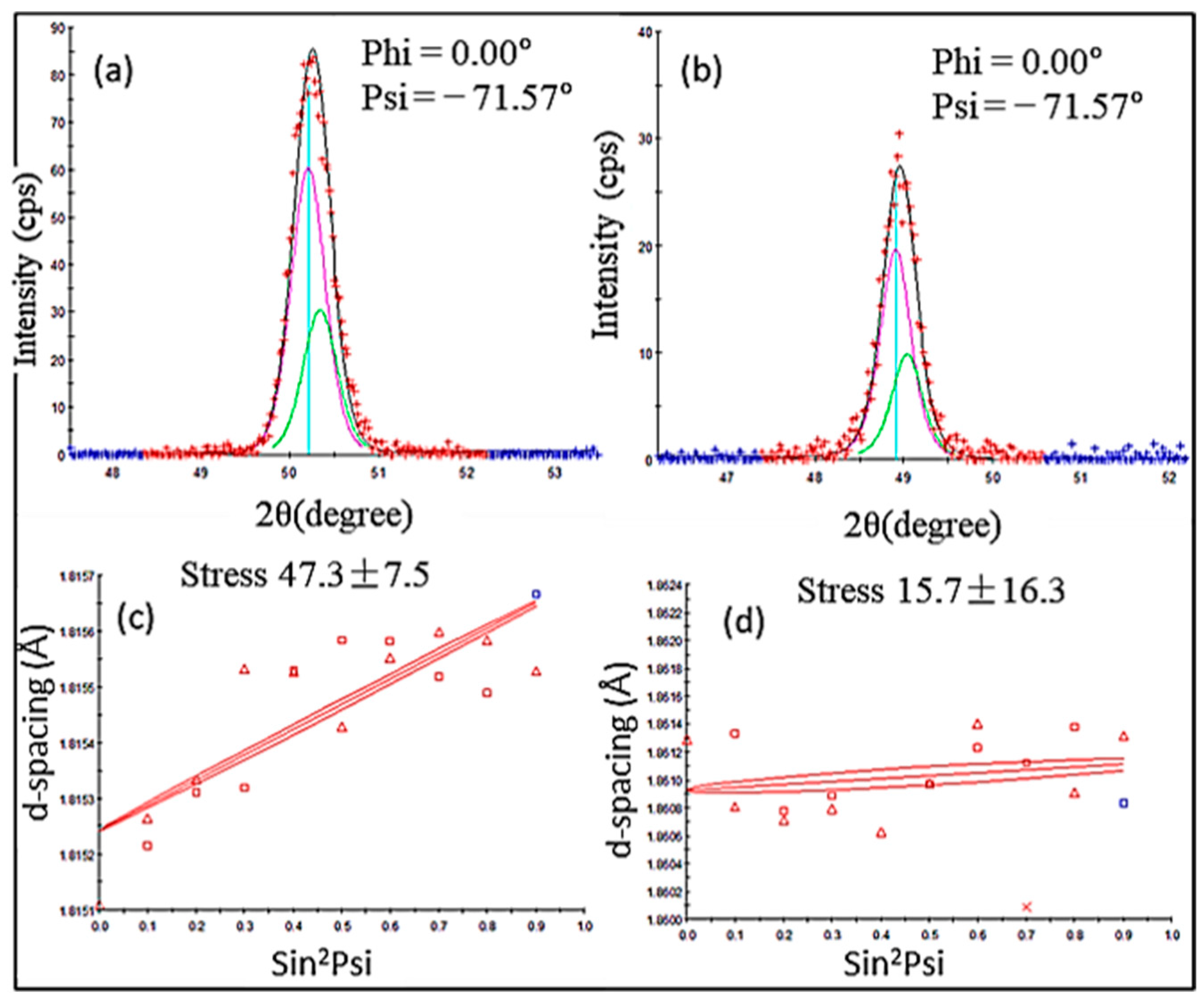
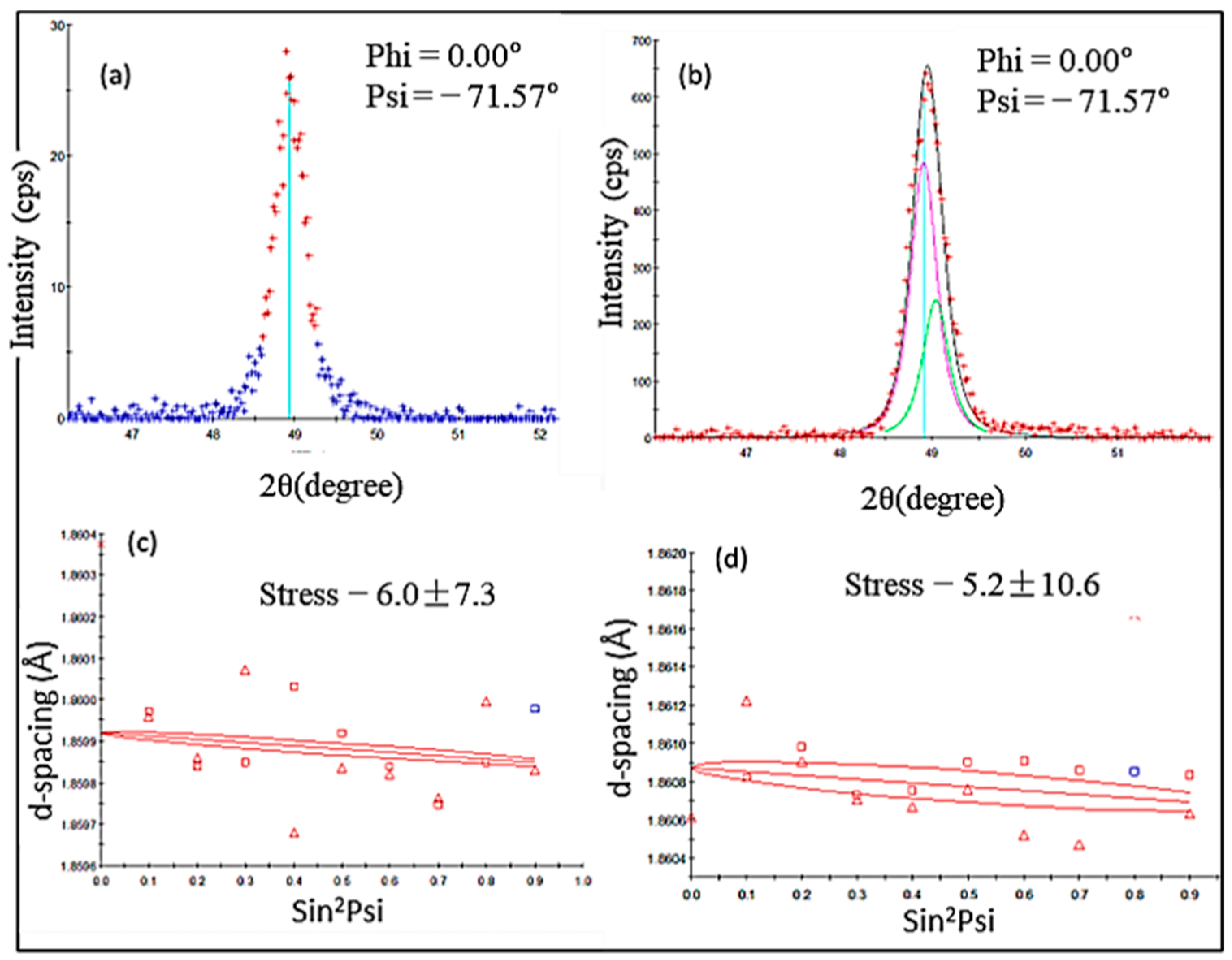
3.3. Residual Stress Measurement

Residual stresses present in the various components are considered a major factor that might impact the life of a component. Usually, metal alloys induce residual stress during the manufacturing process, mostly during the casting process, where the molten alloy metal flows into the casting chamber and cools down from a solid object undergoing phase changes. Similarly, during the thermal spray coating process, the ceramic material coated over the surface of the alloys also develops internal residual stress as they are heated, melted, and accelerated towards the substrate and cooled rapidly.
The XRD pattern indicates the presence of the tetragonal phase of YSZ from the theta position 50.53° JCPDS card no. 48-0224 in the YSZ coating, and the face-centered cubic phase of GZ and GZ DL from the 49.20° two theta position, JCPDS card no 80-0469.
The slopes obtained from the linear fit of the “d vs. sin2ψ” plots are shown in Figure 8 and Figure 9. The residual stress values are identified from the plot from the corresponding peak position in Table 2, and the results are tabulated in Table 3.
Residual stresses of plasma-sprayed YSZ ranging from 20 MPa to 90 MPa have been reported [39,40,41,42]. The calculated value of YSZ falls in this range. The residual stress values of GZ and its bilayer and multilayer coatings have not been calculated in any research articles previously for comparison. However, the Gd2O3-doped YSZ coating residual stress was calculated in previous research work, and it was reported that the residual stress of as-coated YSZ was reduced from ~38 MPa to ~28 MPa for 25% Gd2O3-doped YSZ. Lower compressive stresses in FGC and YSZ/GZ bilayer coatings are considered optimum and reliable compared with the higher tensile stresses present in the single-layer YSZ and GZ coatings. Although few studies are available to compare the stress values of the GZ coating, it is safe to say that the stress values of YSZ calculated using d vs. sin2ψ were comparable with the values found in the literature, and the value calculated for GZ can also be considered to be accurate and reliable.

3.4. Hardness

The hardness of a coating is an important property that determines the ability of the coating to withstand erosion and fracture due to thermal mismatch stresses. Vicker hardness was measured for the TBCs at a 100 g load. Table 4 shows the hardness of the as-coated and heat-treated TBCs. The hardness of plasma-sprayed YSZ improves after heat treatment from 4.4 GPa to 5.04 GPa. This is attributed to the excellent sintering properties of YSZ. However, the hardness of gadolinium zirconate coatings suffers from reduced hardness because of their poor sintering properties. The hardness of the plasma sprayed GZ decreases from 7.74 GPa to 4.36 after heat treatment. The decrease in hardness after heat treatment is due to the softening of the material caused by the increase in surface roughness and porosity. The pores and roughness create weak points that allow for more deformation under applied stress. Plasma-sprayed GZ/YSZ bilayer and FGC TBCs have identical as-coated hardness of 5.84 GPa, which decreases to 4.10 and 4.19 GPa after heat treatment, which is comparable to the hardness value of graded coatings reported in the literature [13].

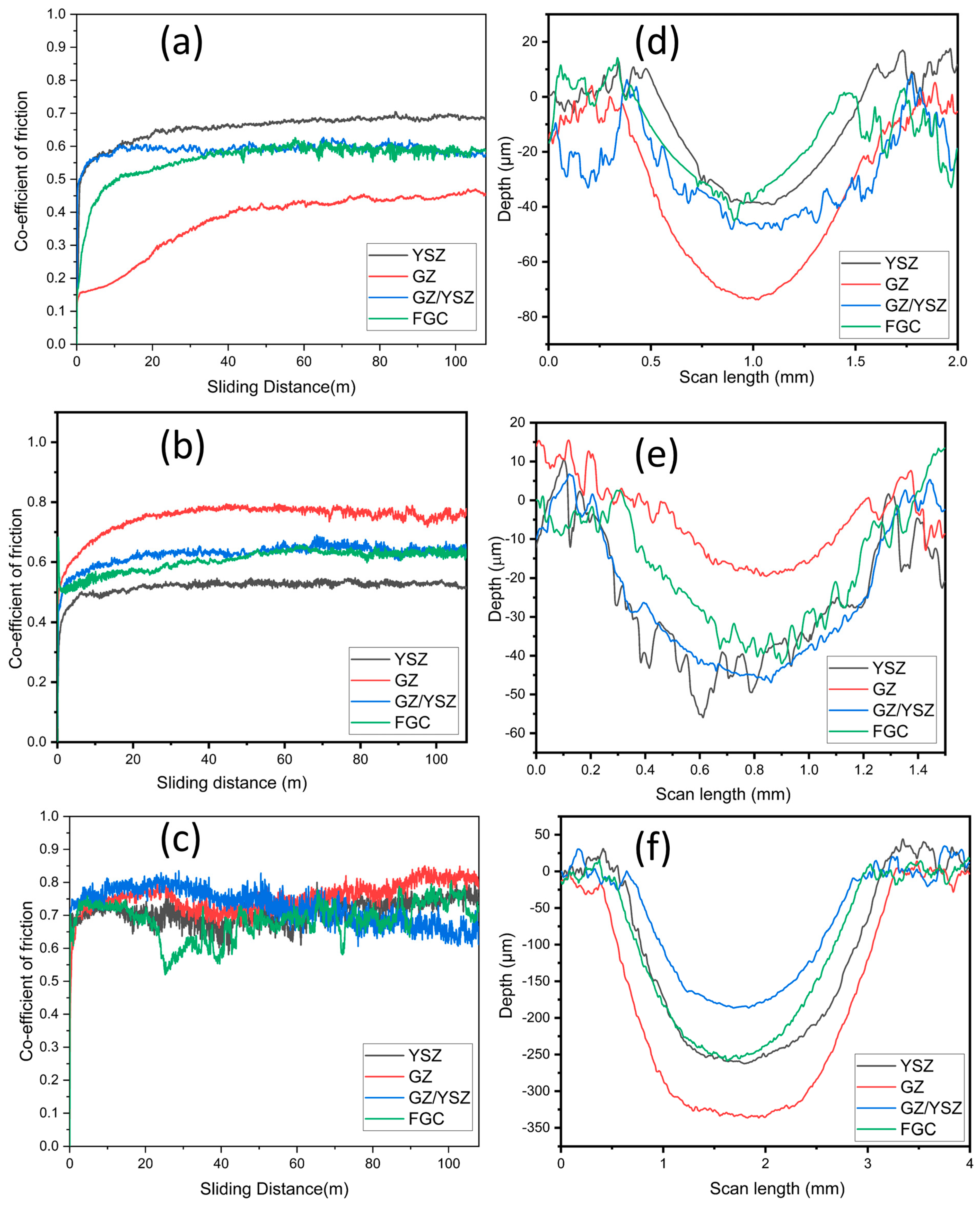
3.5. Tribological Properties

To evaluate the wear resistance of coated and heat-treated TBCs, a sliding wear test was conducted using a linear reciprocating tribometer at room temperature (300 K) and high temperature (673 K). The coefficient of friction (CoF) curves of the as-deposited and heat-treated TBCs with respect to sliding distance are shown in Figure 10a–c. The average CoF values of all the coatings after a 100 m sliding distance are presented in Table 5. A stylus profilometer was used to obtain the depth vs. scan length wear profile, which is depicted in Figure 10d–f. The depth and width of the wear profile provide an indication of the amount of wear.
The wear rate value was calculated using the following formula:
k = V F × S   m m 3 / N m
where k is the wear rate, V is the wear volume, F is the applied load, and S is the total sliding distance. Wear volume can be quantified using the Origin Software 2021 Version 9.8 “area under the curve”. Table 6 shows the wear rate of the coating calculated under different conditions.
Abrasive wear is the primary wear mechanism of all coatings and is primarily governed by the microstructure and mechanical properties of the coatings. Moreover, the wear increases further with a higher sliding temperature (673 K). As-coated GZ exhibits the lowest coefficient of friction. GZ exhibits the highest CoF after heat treatment and during the high-temperature wear test. Gadolinium zirconate (GZ) plasma-sprayed coatings display a unique microstructure involving fine and dense splats composed of abnormal clusters with inter-splat porosity across the surface, as observed through scanning electron microscopy. These clusters aggregate in various sizes. The surface roughness of cubic GZ after heat treatment increases, and hence, the CoF increases.
The CoF of all the TBCs generally increased after heat treatment and during high-temperature wear tests compared with the as-coated coating wear tests. This can be attributed to the fact that the heat treatment increases the surface roughness and reduces porosity, which in turn induces higher frictional energy. However, the wear rate of the GZ coating does not follow this pattern. The wear rate of the as-coated GZ coating reduces significantly, despite the reduced hardness. This can be explained by the softening effect of the cubic GZ after heat treatment. This softer material on the wear path further reduces wear by acting as a lubricant. This is also in line with the fact that the GZ coating has a high as-coated hardness and significantly reduced hardness after heat treatment.
In the case of YSZ, the wear rate increases after heat treatment. Plasma spraying YSZ creates pores and microcracks, leading to nanostructured grains and intricate grain boundaries. Here, the loose debris of plasma-sprayed tetragonal YSZ is hardened and brittle, which facilitates accelerated abrasive wear [43,44,45,46]. For the YSZ/GZ bilayer and FGC, similar coefficients of friction and wear rates were observed. The YSZ/GZ coating observes a reduced wear rate that improves after heat treatment. There was a very small increase in the wear rate in the case of FGC after heat treatment. This can be attributed to the annealing process, which improves the internal stress between YSZ and GZ, resulting in improved wear resistance of the coating. The hardening of YSZ and softening of GZ compensate for each other, which explains the extremely similar wear rate of FGC before and after heat treatment. The calculated wear rate was significantly higher for all coatings tested under 673 K, owing to the increase in abrasive wear nature at elevated temperatures.

4. Conclusions

The YSZ, GZ, YSZ/GZ bilayer, and FGCs of YSZ/GZ were coated through the APS technique. The coatings were analyzed using various characterization techniques and subjected to hot corrosion and wear tests. The XRD analysis of as-coated TBCs revealed that the coating produced matched the expected crystal structure. The YSZ and FGC coatings showed better hot corrosion resistance. The hot corrosion reaction is well arrested to the surface of the coating in the case of FGC because of the formation of GdVO4. However, the mechanical properties of the FGC require improvement. Clearly, gadolinium zirconate has the potential to be used as a suitable replacement for YSZ provided a compatible and optimized TBC system is designed, and future work on this can provide more significant insight into its application in the coating and aerospace industries.

Author Contributions

Conceptualization, R.M. and K.A.; methodology, A.A. and D.K.D.; validation, K.K.A.M., A.A., and G.M.; formal analysis, A.J.; investigation, R.M. and A.J.; data curation, R.M.; writing—original draft preparation, R.M. and A.J.; writing—review and editing, K.K.A.M., G.M., and K.A.; supervision, K.A. and K.K.A.M. All authors have read and agreed to the published version of the manuscript.

Funding

This research was funded by the Indian space research organization (ISRO), Govt. of India (Sanction order no. ISRO/RES/3/811/10-20).

Institutional Review Board Statement

Not applicable.

Informed Consent Statement

Not applicable.

Data Availability Statement

The data are contained within this article.

Acknowledgments

The authors acknowledge the Chancellor, President, and Vice-Chancellor of Sathyabama Institute of Science and Technology, Chennai, for providing the necessary facilities to carry out this research work. We acknowledge the XRD FACILITY at SRMIST set up with support from MNRE (Project No. 31/03/2014-15/PVSE-R&D), Government of India. We also acknowledge SRMIST for the high-resolution scanning electron microscope (HR-SEM) facility.

Conflicts of Interest

The authors declare no conflicts of interest.

References

  1. Clarke, D.R.; Oechsner, M.; Padture, N.P. Thermal-Barrier Coatings for More Efficient Gas-Turbine Engines. MRS Bull. 2012, 37, 891–898. [Google Scholar] [CrossRef]
  2. Deng, W.; Fergus, J.W. Effect of CMAS Composition on Hot Corrosion Behavior of Gadolinium Zirconate Thermal Barrier Coating Materials. J. Electrochem. Soc. 2017, 164, C526–C531. [Google Scholar] [CrossRef]
  3. Kumar, R.; Cietek, D.; Jiang, C.; Roth, J.; Gell, M.; Jordan, E.H. Influence of Microstructure on the Durability of Gadolinium Zirconate Thermal Barrier Coatings Using APS & SPPS Processes. Surf. Coat. Technol. 2018, 337, 117–125. [Google Scholar] [CrossRef]
  4. Frommherz, M.; Scholz, A.; Oechsner, M.; Bakan, E.; Vaßen, R. Gadolinium Zirconate/YSZ Thermal Barrier Coatings: Mixed-Mode Interfacial Fracture Toughness and Sintering Behavior. Surf. Coat. Technol. 2016, 286, 119–128. [Google Scholar] [CrossRef]
  5. Ozgurluk, Y.; Karaoglanli, A.C.; Ahlatci, H. Comparison of Calcium–Magnesium-Alumina-Silicate (CMAS) Resistance Behavior of Produced with Electron Beam Physical Vapor Deposition (EB-PVD) Method YSZ and Gd2Zr2O7/YSZ Thermal Barrier Coatings Systems. Vacuum 2021, 194, 110576. [Google Scholar] [CrossRef]
  6. Sadri, E.; Ashrafizadeh, F.; Eslami, A.; Jazi, H.S.; Ehsaei, H. Thermal Shock Performance and Microstructure of Advanced Multilayer Thermal Barrier Coatings with Gd2Zr2O7 Topcoat. Surf. Coat. Technol. 2022, 448, 128892. [Google Scholar] [CrossRef]
  7. Mahade, S.; Jahagirdar, A.; Li, X.H.; Kjellman, B.; Björklund, S.; Markocsan, N. Tailoring Microstructure of Double-Layered Thermal Barrier Coatings Deposited by Suspension Plasma Spray for Enhanced Durability. Surf. Coat. Technol. 2021, 425, 127704. [Google Scholar] [CrossRef]
  8. Jesuraj, S.A.; Kuppusami, P.; Ch, J.R. Evaluation of Microstructure and Coating Integrity of EB-PVD Deposited Bi-Layers of 7YSZ/Gd2Zr2O7 and 7YSZ/Y2O3-Gd2Zr2O7 Top Coats on Bond Coated Superalloys. Surf. Coat. Technol. 2022, 440, 128488. [Google Scholar] [CrossRef]
  9. Vaßen, R.; Bakan, E.; Mack, D.; Schwartz-Lückge, S.; Sebold, D.; Jung Sohn, Y.; Zhou, D.; Guillon, O. Performance of YSZ and Gd2Zr2O7/YSZ Double Layer Thermal Barrier Coatings in Burner Rig Tests. J. Eur. Ceram. Soc. 2020, 40, 480–490. [Google Scholar] [CrossRef]
  10. Mahade, S.; Curry, N.; Björklund, S.; Markocsan, N.; Nylén, P. Thermal Conductivity and Thermal Cyclic Fatigue of Multilayered Gd2Zr2O7/YSZ Thermal Barrier Coatings Processed by Suspension Plasma Spray. Surf. Coat. Technol. 2015, 283, 329–336. [Google Scholar] [CrossRef]
  11. Schulz, U.; Nowotnik, A.; Kunkel, S.; Reiter, G. Effect of Processing and Interface on the Durability of Single and Bilayer 7YSZ/Gadolinium Zirconate EB-PVD Thermal Barrier Coatings. Surf. Coat. Technol. 2020, 381, 125107. [Google Scholar] [CrossRef]
  12. Mahade, S.; Zhou, D.; Curry, N.; Markocsan, N.; Nylén, P.; Vaßen, R. Tailored Microstructures of Gadolinium Zirconate/YSZ Multi-Layered Thermal Barrier Coatings Produced by Suspension Plasma Spray: Durability and Erosion Testing. J. Mater. Process. Technol. 2019, 264, 283–294. [Google Scholar] [CrossRef]
  13. Carpio, P.; Bannier, E.; Salvador, M.D.; Benavente, R.; Sánchez, E. Multilayer and Particle Size-Graded YSZ Coatings Obtained by Plasma Spraying of Micro- and Nanostructured Feedstocks. J. Therm. Spray Technol. 2014, 23, 1362–1372. [Google Scholar] [CrossRef]
  14. Carpio, P.; Salvador, M.D.; Borrell, A.; Sánchez, E. Thermal Behaviour of Multilayer and Functionally-Graded YSZ/Gd2Zr2O7 Coatings. Ceram. Int. 2017, 43, 4048–4054. [Google Scholar] [CrossRef]
  15. Carpio, P.; Rayón, E.; Salvador, M.D.; Lusvarghi, L.; Sánchez, E. Mechanical Properties of Double-Layer and Graded Composite Coatings of YSZ Obtained by Atmospheric Plasma Spraying. J. Therm. Spray Technol. 2016, 25, 778–787. [Google Scholar] [CrossRef]
  16. Khan, M.A.; Anand, A.V.; Duraiselvam, M.; Rao, K.S.; Singh, R.A.; Jayalakshmi, S. Thermal Shock Resistance and Thermal Insulation Capability of Laser-Glazed Functionally Graded Lanthanum Magnesium Hexaluminate/Yttria-Stabilised Zirconia Thermal Barrier Coating. Materials 2021, 14, 3865. [Google Scholar] [CrossRef] [PubMed]
  17. Mohammadzaki Goudarzi, Z.; Valefi, Z.; Zamani, P. Effect of Functionally Graded Structure Design on Durability and Thermal Insulation Capacity of Plasma-Sprayed Thick Thermal Barrier Coating. Ceram. Int. 2021, 47, 34361–34379. [Google Scholar] [CrossRef]
  18. Sathish, M.; Radhika, N.; Saleh, B. A Critical Review on Functionally Graded Coatings: Methods, Properties, and Challenges. Compos. Part B Eng. 2021, 225, 109278. [Google Scholar] [CrossRef]
  19. Amer, M.; Curry, N.; Hayat, Q.; Sharma, R.; Janik, V.; Zhang, X.; Nottingham, J.; Bai, M. Cracking Behavior of Gd2Zr2O7/YSZ Multi-Layered Thermal Barrier Coatings Deposited by Suspension Plasma Spray. Coatings 2023, 13, 107. [Google Scholar] [CrossRef]
  20. Guven Gok, M.; Goller, G. Production and Characterisation of GZ/CYSZ Alternative Thermal Barrier Coatings with Multilayered and Functionally Graded Designs. J. Eur. Ceram. Soc. 2016, 36, 1755–1764. [Google Scholar] [CrossRef]
  21. Vakilifard, H.; Ghasemi, R.; Rahimipour, M. Hot Corrosion Behaviour of Plasma-Sprayed Functionally Graded Thermal Barrier Coatings in the Presence of Na2SO4+V2O5 Molten Salt. Surf. Coat. Technol. 2017, 326, 238–246. [Google Scholar] [CrossRef]
  22. Habibi, M.H.; Wang, L.; Guo, S.M. Evolution of Hot Corrosion Resistance of YSZ, Gd2Zr2O7, and Gd2Zr2O7+YSZ Composite Thermal Barrier Coatings in Na 2SO4+V2O5 at 1050 °C. J. Eur. Ceram. Soc. 2012, 32, 1635–1642. [Google Scholar] [CrossRef]
  23. Khajezadeh, M.H.; Mohammadi, M.; Ghatee, M. Hot Corrosion Performance and Electrochemical Study of CoNiCrAlY/YSZ/YSZ-La2O3 Multilayer Thermal Barrier Coatings in the Presence of Molten Salt. Mater. Chem. Phys. 2018, 220, 23–34. [Google Scholar] [CrossRef]
  24. Mahade, S.; Jonnalagadda, K.P.; Curry, N.; Li, X.H.; Björklund, S.; Markocsan, N.; Nylén, P.; Peng, R.L. Engineered Architectures of Gadolinium Zirconate Based Thermal Barrier Coatings Subjected to Hot Corrosion Test. Surf. Coat. Technol. 2017, 328, 361–370. [Google Scholar] [CrossRef]
  25. Wang, Y.; Zhao, Y.; Darut, G.; Poirier, T.; Stella, J.; Wang, K.; Liao, H.; Planche, M.P. A Novel Structured Suspension Plasma Sprayed YSZ-PTFE Composite Coating with Tribological Performance Improvement. Surf. Coat. Technol. 2019, 358, 108–113. [Google Scholar] [CrossRef]
  26. Darut, G.; Ageorges, H.; Denoirjean, A.; Fauchais, P. Tribological Performances of YSZ Composite Coatings Manufactured by Suspension Plasma Spraying. Surf. Coat. Technol. 2013, 217, 172–180. [Google Scholar] [CrossRef]
  27. Azhar, A.Z.A.; Ratnam, M.M.; Ahmad, Z.A. Effect of Al2O3/YSZ Microstructures on Wear and Mechanical Properties of Cutting Inserts. J. Alloy. Compd. 2009, 478, 608–614. [Google Scholar] [CrossRef]
  28. Rajasekaramoorthy, M.; Karthikeyan, A.; Anderson, A.; KamalanKirubaharan, A.M. Thermal Shock Resistance Behaviour of Multilayered Gd2O3 Doped YSZ on Inconel-718 Substrate. Mater. Today Proc. 2020, 33, 1011–1014. [Google Scholar] [CrossRef]
  29. Ejaz, N.; Ali, L.; Ahmed, A.; Rafiq, A.; Awan, G.H.; Mehmood, K. Sulfate-Vanadate Hot Corrosion of Neodymium Cerate/Yttria Stabilized Zirconia Composite Coating. Int. J. Appl. Ceram. Technol. 2019, 16, 931–942. [Google Scholar] [CrossRef]
  30. Palareti, G.; Legnani, C.; Cosmi, B.; Antonucci, E.; Erba, N.; Poli, D.; Testa, S.; Tosetto, A. Comparison between Different D-Dimer Cutoff Values to Assess the Individual Risk of Recurrent Venous Thromboembolism: Analysis of Results Obtained in the DULCIS Study. Int. J. Lab. Hematol. 2016, 38, 42–49. [Google Scholar] [CrossRef]
  31. Kamalan Kirubaharan, A.M.; Kuppusami, P.; Dharini, T. Thermal Expansion Studies of Electron Beam Evaporated Yttria Films on Inconel-718 Substrates. Surf. Coat. Technol. 2018, 354, 297–305. [Google Scholar] [CrossRef]
  32. Kamalan Kirubaharan, A.M.; Kuppusami, P.; Chakravarty, S.; Ramachandran, D.; Singh, A. Thermal Expansion and Residual Stress Behaviour of Electron Beam Evaporated Yttria Stabilized Zirconia Films on Inconel-690 Substrates. J. Alloys Compd. 2017, 722, 585–592. [Google Scholar] [CrossRef]
  33. Pakseresht, A.H.; Javadi, A.H.; Bahrami, M.; Khodabakhshi, F.; Simchi, A. Spark Plasma Sintering of a Multilayer Thermal Barrier Coating on Inconel 738 Superalloy: Microstructural Development and Hot Corrosion Behavior. Ceram. Int. 2016, 42, 2770–2779. [Google Scholar] [CrossRef]
  34. Thirumalaikumarasamy, D.; Shanmugam, K.; Balasubramanian, V. Influences of Atmospheric Plasma Spraying Parameters on the Porosity Level of Alumina Coating on AZ31B Magnesium Alloy Using Response Surface Methodology. Prog. Nat. Sci. Mater. Int. 2012, 22, 468–479. [Google Scholar] [CrossRef]
  35. Jesuraj, S.A.; Kuppusami, P.; Dharini, T.; Panda, P.; Devapal, D. Effect of Substrate Temperature on Microstructure and Nanomechanical Properties of Gd2Zr2O7 Coatings Prepared by EB-PVD Technique. Ceramics International 2018, 44, 18164–18172. [Google Scholar] [CrossRef]
  36. Kaushal, S.; Singh, S. Slurry Erosion Behavior of Plasma Sprayed Coating on Turbine Steel. Ind. Lubr. Tribol. 2019, 71, 1–9. [Google Scholar] [CrossRef]
  37. Jonnalagadda, K.P.; Mahade, S.; Curry, N.; Li, X.H.; Markocsan, N.; Nylén, P.; Björklund, S.; Peng, R.L. Hot Corrosion Mechanism in Multi-Layer Suspension Plasma Sprayed Gd2Zr2O7/YSZ Thermal Barrier Coatings in the Presence of V2O5+Na2SO4. J. Therm. Spray Technol. 2017, 26, 140–149. [Google Scholar] [CrossRef]
  38. Hao, J.K.C.; Azhar, A.Z.A.; Ratnam, M.M.; Ahmad, Z.A. Wear Performance and Mechanical Properties of 80 Wt-%Al2O3/20 Wt-%YSZ Cutting Inserts at Different Sintering Rates and Soaking Times. Mater. Sci. Technol. 2010, 26, 95–103. [Google Scholar] [CrossRef]
  39. Chen, Q.; Mao, W.G.; Zhou, Y.C.; Lu, C. Effect of Young’s Modulus Evolution on Residual Stress Measurement of Thermal Barrier Coatings by X-ray Diffraction. Appl. Surf. Sci. 2010, 256, 7311–7315. [Google Scholar] [CrossRef]
  40. Kamalan Kirubaharan, A.M.; Anderson, A.; Thykattusserry, N.J.; Rajasekaramoorthy, M.; Surya Saketh, M.; Bhargav, P. Measurement of Residual Stress in Thermal Barrier Coating Using GIXRD. Mater. Today Proc. 2021, 44, 3575–3577. [Google Scholar] [CrossRef]
  41. Li, C.; Jacques, S.D.M.; Chen, Y.; Daisenberger, D.; Xiao, P.; Markocsan, N.; Nylen, P.; Cernik, R.J. A Synchrotron X-ray Diffraction Deconvolution Method for the Measurement of Residual Stress in Thermal Barrier Coatings as a Function of Depth. J. Appl. Crystallogr. 2016, 49, 1904–1911. [Google Scholar] [CrossRef] [PubMed]
  42. Mao, W.G.; Chen, Q.; Dai, C.Y.; Yang, L.; Zhou, Y.C.; Lu, C. Effects of Piezo-Spectroscopic Coefficients of 8 wt.% Y2O3 Stabilized ZrO2 on Residual Stress Measurement of Thermal Barrier Coatings by Raman Spectroscopy. Surf. Coat. Technol. 2010, 204, 3573–3577. [Google Scholar] [CrossRef]
  43. Dharini, T.; Kuppusami, P.; Kumar, N.; Kumar, D.D.; Soman, A.K.; Kirubaharan, A.M.K. Tribological Properties of YSZ and YSZ/Ni-YSZ Nanocomposite Coatings Prepared by Electron Beam Physical Vapour Deposition. Ceram. Int. 2021, 47, 26010–26018. [Google Scholar] [CrossRef]
  44. Pakseresht, A.H.; Saremi, M.; Omidvar, H.; Alizadeh, M. Micro-Structural Study and Wear Resistance of Thermal Barrier Coating Reinforced by Alumina Whisker. Surf. Coat. Technol. 2019, 366, 338–348. [Google Scholar] [CrossRef]
  45. Murray, J.W.; Leva, A.; Joshi, S.; Hussain, T. Microstructure and Wear Behaviour of Powder and Suspension Hybrid Al2O3–YSZ Coatings. Ceram. Int. 2018, 44, 8498–8504. [Google Scholar] [CrossRef]
  46. Ramachandran, C.S.; Balasubramanian, V.; Ananthapadmanabhan, P.V.; Viswabaskaran, V. Understanding the Dry Sliding Wear Behaviour of Atmospheric Plasma-Sprayed Rare Earth Oxide Coatings. Mater. Des. 2012, 39, 234–252. [Google Scholar] [CrossRef]
Figure 1. Schematic representation of TBCs: (a) YSZ, (b) GZ, (c) YSZ/GZ bilayer, and (d) FGC of YSZ/GZ.
Ceramics 07 00038 g001
Figure 2. High magnification FE-SEM images of (a) NiCrAlY bond coat powder, (b) YSZ and, (c) GZ.
Ceramics 07 00038 g002
Figure 3. Corrosive salt paste was applied to samples on (a) YSZ, (b) GZ, (c) YSZ/GZ bilayer, and (d) FGC TBCs. Images after hot corrosion tests of (e) YSZ (f) GZ (g) YSZ/GZ, (h) delaminated top layer of YSZ/GZ, and (i) FGC.
Ceramics 07 00038 g003
Figure 4. XRD pattern of (a) as-coated YSZ and (b) YSZ after the hot corrosion test and (c) as-coated GZ and (d) GZ after the hot corrosion test.
Ceramics 07 00038 g004
Figure 5. XRD pattern of the (a) as-coated YSZ/GZ bilayer and (b) YSZ/GZ bilayer after the hot corrosion test and (c) as-coated FGC and (d) FGC after the hot corrosion test.
Ceramics 07 00038 g005
Figure 6. High-magnification HR-SEM images of as-coated TBCs (a) YSZ, (b) GZ, (c) YSZ/GZ, and (d) FGC and high-magnification HR SEM images of hot corrosion-tested samples (e) YSZ, (f) GZ, (g) the YSZ/GZ bilayer, and (h) FGC.
Ceramics 07 00038 g006
Figure 7. SEM micrographs and EDS spectra of TBCs after the hot corrosion test: (a) SEM micrograph of YSZ and (b) EDS spectrum of YSZ. (c) SEM micrograph of GZ, (d) EDS spectrum of GZ, (e) SEM micrograph of the YSZ/GZ bilayer, (f) EDS spectrum of the YSZ/GZ bilayer, (g) SEM micrograph of FGC TBC, and (h) EDS spectrum of FGC TBC.
Ceramics 07 00038 g007
Figure 8. Residual stress measurement plots: (a) YSZ XRD pattern, (b) GZ XRD pattern, (c) YSZ d vs. sin2ψ plot, and (d) GZ d vs. sin2ψ plot.
Ceramics 07 00038 g008
Figure 9. Residual stress measurement plots: (a) DL XRD pattern, (b) FGC XRD pattern, (c) YSZ/GZ bilayer, d vs. sin2ψ plot, and (d) FGC d vs. sin2ψ plot.
Ceramics 07 00038 g009
Figure 10. Coefficient of friction vs. sliding distance of coatings (a) as-coated TBC, (b) heat-treated TBC, and (c) wear at high temperature (673 K) and depth vs. scan length wear profile of (d) as-coated TBC, (e) heat-treated TBC, and (f) wear profile at high temperature.
Ceramics 07 00038 g010
Table 1. Process parameters for the deposition of the bond coat and ceramic topcoat.
ParametersValue
Power (KW)40
Current (A)500
Voltage (V)65–70
Primary gas (argon) flow rate (LPM)80–90
Secondary gas (hydrogen) flow rate (LPM)15–18
Distance (mm)80
Spray angle (degrees)90
Table 2. Details for residual stress measurement.
S. No.CoatingJCPDS Card No.Peak Position (2θ)(hkl)Elastic Modulus, E (GPa)Poisson’s Ratio, ν
1YSZ48-022450.53(112)2280.20
2GZ80-046949.20(440)1750.23
3DL80-046949.20(440)1750.23
4FGC80-046949.20(440)1750.23
Table 3. Residual stress values in the coatings.
S. No.CoatingPeak Angle (2θ°)(hkl)Stress, MPaTensile/Compressive
1YSZ50.5311247.3 ± 7.5Tensile
2GZ49.2044015.7 ± 16.3Tensile
3YSZ/GZ49.20440−6.0 ± 7.3Compressive
4FGC49.20440−15.2 ± 10.6Compressive
Table 4. Vicker’s hardness of the TBC coatings.
CoatingAs-Coated TBCHeat-Treated TBC
HV 0.1Equivalent, GPaHV 0.1Equivalent, GPa
YSZ449 ± (10)4.40514 ± (26)5.04
GZ789 ± (38)7.74445 ± (9)4.36
YSZ/GZ595 ± (11)5.84418 ± (11)4.10
FGC595 ± (20)5.84427 ± (12)4.19
Table 5. Coefficient of friction at a 100 m sliding distance.
CoatingCoefficient of Friction of As-Coated TBCsCoefficient of Friction of Heat-Treated TBCsCoefficient of Friction of As-Coated TBCs at 673 K
YSZ0.690.540.76
GZ0.450.740.81
YSZ/GZ0.580.630.63
FGC0.590.620.74
Table 6. Wear rate values of TBCs.
CoatingWear Rate of As-Coated TBCs (×10−4 mm3/Nm)Wear Rate of Heat-Treated TBCs (×10−4 mm3/Nm)Wear Rate of As-Coated TBCs at 673 K (×10−2 mm3/Nm)
YSZ3.074.315.61
GZ7.911.188.52
YSZ/GZ5.424.343.43
FGC2.903.045.10
Disclaimer/Publisher’s Note: The statements, opinions and data contained in all publications are solely those of the individual author(s) and contributor(s) and not of MDPI and/or the editor(s). MDPI and/or the editor(s) disclaim responsibility for any injury to people or property resulting from any ideas, methods, instructions or products referred to in the content.

