Properties of 2 mol% Yttria Stabilized Zirconia–Alumina–Cerium Hexaaluminate Composites


Abstract
1. Introduction
2. Materials and Methods
3. Results
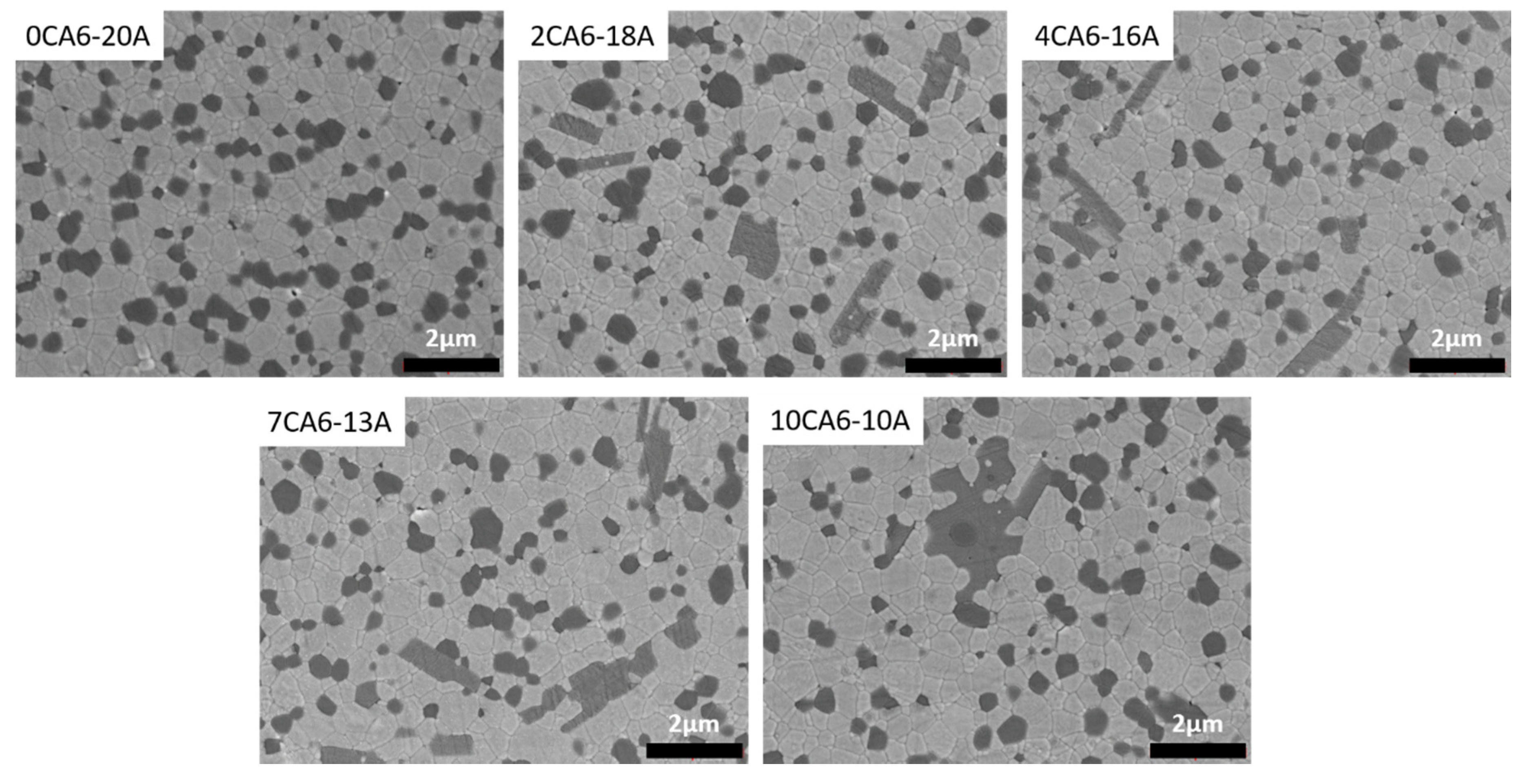
3.1. Microstructure
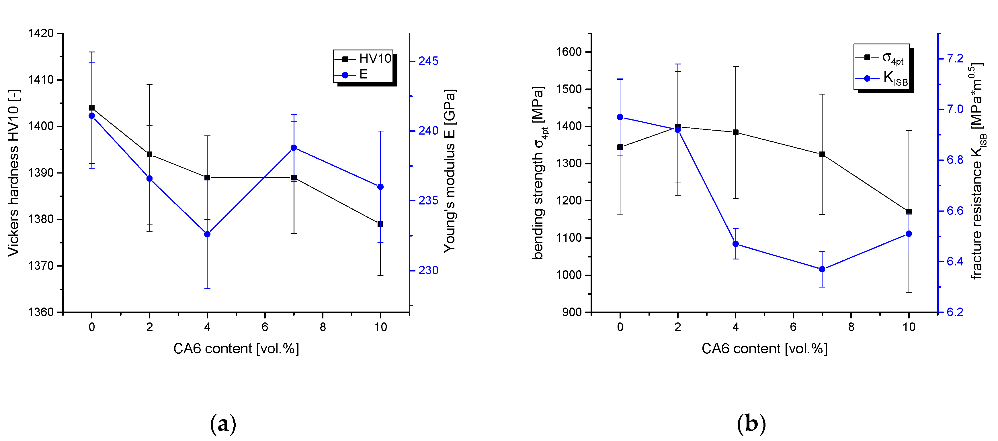
3.2. Mechanical Properties
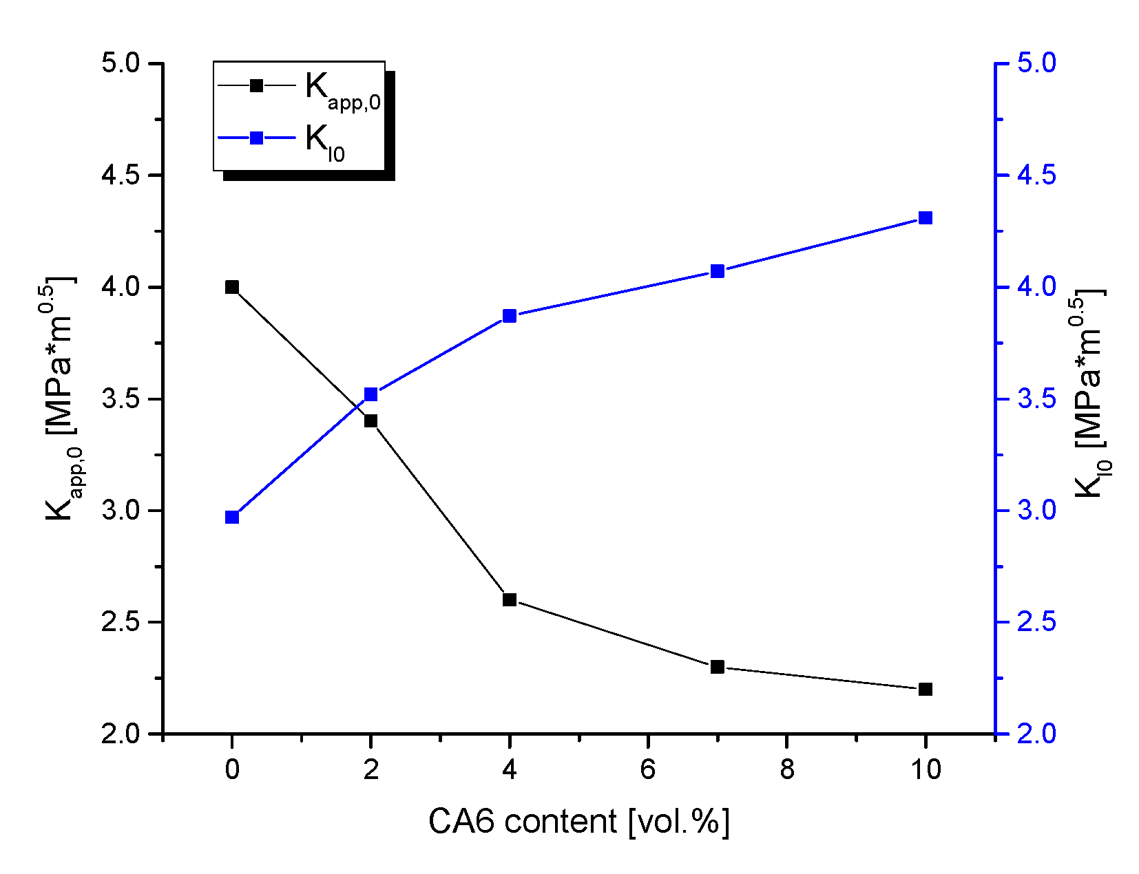
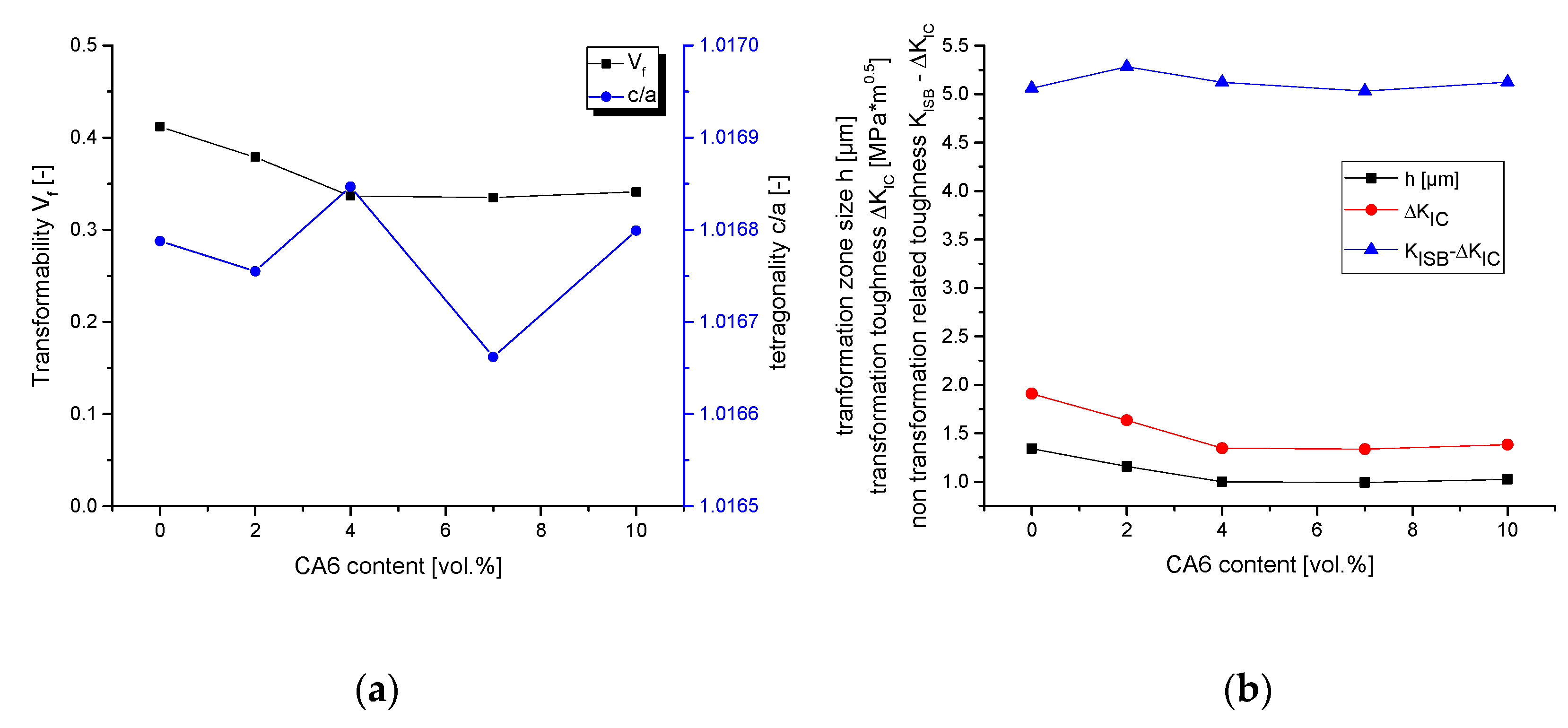
3.3. Phase Composition and Calculation of Transformation Toughness
4. Discussion
5. Conclusions
Funding
Acknowledgments
Conflicts of Interest
References
- Garvie, R.C.; Hannink, R.H.; Pascoe, R.T. Ceramic steel? Nature 1975, 258, 703–704. [Google Scholar] [CrossRef]
- Hannink, R.H.J.; Kelly, P.M.; Muddle, B.C. Transformation Toughening in Zirconia-Containing Ceramics. J. Am. Ceram. Soc. 2000, 83, 461–487. [Google Scholar] [CrossRef]
- Kelly, P.M.; Francis Rose, L.R. The martensitic transformation in ceramics—Its role in transformation toughening. Prog. Mater. Sci. 2002, 47, 463–557. [Google Scholar] [CrossRef]
- Swain, M.V.; Rose, L.R.F. Strength Limitations of Transformation-Toughened Zirconia Alloys. J. Am. Ceram. Soc. 1986, 69, 511–518. [Google Scholar] [CrossRef]
- Ross, I.M.; Rainforth, W.M.; McComb, D.W.; Scott, A.J.; Brydson, R. The role of trace additions of alumina to yttria partially stabilized zirconia (Y-TZP). Scripta Materialia. 2001, 45, 653–660. [Google Scholar] [CrossRef]
- Tsukuma, K.; Ueda, K.; Shimada, K. Strength and Fracture Toughness of Isostatically Hot-Pressed Composites of Al2O3 and Y2O3-Partially-Stabilized ZrO2. J. Am. Ceram. Soc. 1985, 68, C4–C5. [Google Scholar] [CrossRef]
- Cutler, R.A.; Mayhew, R.J.; Prettiman, K.M.; Virkar, A. High-Toughness Ce-TZP/Al2O3 Ceramics with Improved Hardness and Strength. J. Am. Ceram. Soc. 1991, 74, 179–186. [Google Scholar] [CrossRef]
- Nawa, M.; Nakamoto, S.; Sekino, T.; Niihara, K. Tough and Strong Ce-TZP/Alumina Nanocomposites Doped with Titania. Ceram. Int. 1998, 24, 497–506. [Google Scholar] [CrossRef]
- Benzaid, R.; Chevalier, J.; Saâdaoui, M.; Fantozzi, G.; Nawa, M.; Diaz, L.A.; Torrecillas, R. Fracture toughness, strength and slow crack growth in a ceria stabilized zirconia–alumina nanocomposite for medical applications. Biomaterials 2008, 29, 3636–3641. [Google Scholar] [CrossRef]
- Miura, M.; Hongoh, H.; Yogo, T.; Hirano, S.; Fujii, T. Formation of plate-like lanthanum-13-Aluminate crystal in Ce-TZP matrix. J. Mat. Sci. 1994, 29, 262–268. [Google Scholar] [CrossRef]
- Yamaguchi, T.; Sakamoto, W.; Yogo, T.; Fujii, T.; Hirano, S. In situ formation of Ce-TZP/Ba-Hexaaluminate composites. J. Ceram. Soc. Jpn. 1999, 107, 814–819. [Google Scholar] [CrossRef]
- Tsai, J.F.; Chon, U.; Ramachandran, N.; Shetty, D.K. Transformation Plasticity and Toughening in CeO2-Partially-Stabilized Zirconia–Alumina (Ce-TZP/Al2O3) Composites Doped with MnO. J. Am. Ceram. Soc. 1992, 75, 1219–1238. [Google Scholar] [CrossRef]
- Kern, F.; Gadow, R. Influence of In-Situ Platelet Reinforcement on the Properties of Injection Moulded Alumina-Toughened Zirconia. J. Ceram. Sci. Technol. 2011, 2, 47–54. [Google Scholar]
- Kern, F. A comparison of microstructure and mechanical properties of 12Ce-TZP reinforced with alumina and in situ formed strontium- or lanthanum hexaaluminate precipitates. J. Eur. Ceram. Soc. 2014, 34, 413–423. [Google Scholar] [CrossRef]
- Gottwik, L.; Wippermann, A.; Kuntz, M.; Denkena, B. Effect of strontium hexaaluminate addition on the damage-tolerance of yttria-stabilized zirconia. Ceram. Int. 2017, 43, 15891–15898. [Google Scholar] [CrossRef]
- Tsukuma, K. Conversion from β-Ce2O3∙11 Al2O3 to α-Al2O3 in Tetragonal ZrO2 Matrix. J. Am. Ceram. Soc. 2000, 83, 3219–3221. [Google Scholar] [CrossRef]
- Evans, A.G.; He, M.Y.; Hutchinson, J.W. Interface Debonding and Fiber Cracking in Brittle Matrix Composites. J. Am. Ceram. Soc. 1989, 72, 2300–2303. [Google Scholar] [CrossRef]
- Schmid, C.; Lucchini, E.; Sbaizero, O.; Maschio, S. The Synthesis of Calcium or Strontium Hexaluminate Added ZTA Composite Ceramics. J. Eur. Ceram. Soc. 1999, 19, 1741–1746. [Google Scholar] [CrossRef]
- Lange, F.F. Transformation toughening—Part 3: Experimental Observations in the ZrO2-Y2O3-System. J. Mater. Sci. 1982, 17, 240–246. [Google Scholar] [CrossRef]
- Chen, P.L.; Chen, I.W. In-Situ Alumina/Aluminate Platelet Composites. J. Am. Ceram. Soc. 1992, 75, 2610–2612. [Google Scholar] [CrossRef]
- Kingery, D.; Bowen, H.K.; Uhlmann, R. Introduction to Ceramics; Wiley: New York, NY, USA, 1976; p. 785. [Google Scholar]
- Becher, P.F.; Hsueh, C.-H.; Angelini, P.; Tiegs, T.N. Toughening Behavior in Whisker-Reinforced Ceramic Matrix Composites. J. Am. Ceram. Soc. 1988, 71, 1050–1061. [Google Scholar] [CrossRef]
- Kern, F.; Reveron, H.; Chevalier, J.; Gadow, R. Mechanical behaviour of extremely tough TZP bioceramics. J. Mech. Behav. Biomater. 2018, 90, 395–403. [Google Scholar] [CrossRef] [PubMed]
- Calado, J. Ceramic powder production with emulsion detonation synthesis. CFI/Ber. DKG 2016, 93, E32–E34. [Google Scholar]
- Kern, F. Effect of In Situ-Formed Cerium Hexaaluminate Precipitates on Properties of Alumina -24 Vol% Zirconia (1.4Y) Composites. J. Ceram. Sci. Technol. 2013, 4, 177–186. [Google Scholar]
- Chantikul, P.; Anstis, G.R.; Lawn, B.R.; Marshall, D.B. A Critical Evaluation of Indentation Techniques for Measuring Fracture Toughness: II, Strength method. J. Am. Ceram. Soc. 1981, 64, 539–543. [Google Scholar] [CrossRef]
- Dransmann, G.W.; Steinbrech, R.W.; Pajares, A.; Guiberteau, F.; Dominguez-Rodriguez, A.; Heuer, A. Indentation Studies on Y2O3-Stabilized ZrO2: II, Toughness Determination from Stable Growth of Indentation-Induced Cracks. J. Am. Ceram. Soc. 1994, 77, 1194–1201. [Google Scholar] [CrossRef]
- De Aza, A.H.; Chevalier, J.; Fantozzi, G.; Schehl, M.; Torrecillas, R. Slow-Crack-Growth Behavior of Zirconia-Toughened Alumina Ceramics Processed by Different Methods. J. Am. Ceram. Soc. 2003, 86, 115–120. [Google Scholar] [CrossRef]
- Toraya, H.; Yoshimura, M.; Somiya, S. Calibration Curve for Quantitative Analysis of the Monoclinic-Tetragonal ZrO2 System by X-Ray Diffraction. J. Am. Ceram. Soc. 1984, 67, C119–C121. [Google Scholar]
- Nakayama, S.; Maekawa, S.; Sato, T.; Masuda, Y.; Imai, S.; Sakamoto, M. Mechanical properties of ytterbia stabilized zirconia ceramics (Yb-TZP) fabricated from powders prepared by co-precipitation method. Ceram. Int. 2000, 26, 207–211. [Google Scholar] [CrossRef]
- Scott, H.G. Phase relationships in the zirconia-yttria system. J. Mater. Sci. 1975, 10, 1527–1535. [Google Scholar] [CrossRef]
- Kosmac, T.; Wagner, R.; Claussen, N. X-ray Determination of Transformation Depths in Ceramics Containing Tetragonal ZrO2. J. Am. Ceram. Soc. 1981, 64, C72–C73. [Google Scholar] [CrossRef]
- McMeeking, R.M.; Evans, A.G. Mechanics of Transformation-Toughening in Brittle Materials. J. Am. Ceram. Soc. 1982, 65, 242–246. [Google Scholar] [CrossRef]
- Kao, H.C.; Ho, F.Y.; Yang, C.C.; Wei, W.J. Surface machining of Fine-grain Y-TZP. J. Eur. Ceram. Soc. 2000, 20, 2447–2455. [Google Scholar] [CrossRef]
- Zhang, F.; Vanmeensel, K.; Inokoshi, M.; Batuk, M.; Hadermann, J.; van Meerbeek, B.; Naert, I.; Vleugels, J. 3Y-TZP ceramics with improved hydrothermal degradation resistance and fracture toughness. J. Eur. Ceram. Soc. 2014, 34, 2453–2463. [Google Scholar] [CrossRef]


© 2020 by the author. Licensee MDPI, Basel, Switzerland. This article is an open access article distributed under the terms and conditions of the Creative Commons Attribution (CC BY) license (http://creativecommons.org/licenses/by/4.0/).
Share and Cite
Kern, F. Properties of 2 mol% Yttria Stabilized Zirconia–Alumina–Cerium Hexaaluminate Composites. Ceramics 2020, 3, 190-198. https://doi.org/10.3390/ceramics3020017
Kern F. Properties of 2 mol% Yttria Stabilized Zirconia–Alumina–Cerium Hexaaluminate Composites. Ceramics. 2020; 3(2):190-198. https://doi.org/10.3390/ceramics3020017
Chicago/Turabian StyleKern, Frank. 2020. "Properties of 2 mol% Yttria Stabilized Zirconia–Alumina–Cerium Hexaaluminate Composites" Ceramics 3, no. 2: 190-198. https://doi.org/10.3390/ceramics3020017
APA StyleKern, F. (2020). Properties of 2 mol% Yttria Stabilized Zirconia–Alumina–Cerium Hexaaluminate Composites. Ceramics, 3(2), 190-198. https://doi.org/10.3390/ceramics3020017