Article

Thermomechanical Characterisation of Mullite Zirconia Composites Sintered from Andalusite for High Temperature Applications

by
Thierry Chotard
1,*,
Lizeth Arbelaez Morales
1,
Marie-Laure Bouchetou
2 and
Jacques Poirier
2
1
Institut de R echerche sur les Ceramiques IRCER UMR 7315 CNRS, Université de Limoges, 12 rue Atlantis 87068 Limoges cedex, France
2
Conditions Extrêmes et Matériaux: Haute Température et Irradiation CEMHTI UPR 3079 CNRS, Université d’Orléans, 1 Avenue de la Recherche Scientifique, 45100 Orléans, France
*
Author to whom correspondence should be addressed.
Ceramics 2019, 2(4), 587-601; https://doi.org/10.3390/ceramics2040046
Submission received: 10 November 2019 / Revised: 27 November 2019 / Accepted: 2 December 2019 / Published: 6 December 2019
(This article belongs to the Special Issue Design, Properties, Damage and Lifetime of Refractory Ceramics)

Abstract

:
Mullite-Zirconia refractories are well known for their good resistance to corrosion and thermal shock. In this study, several mullite-zirconia composites were developed from andalusite, alumina and zircon sintered at 1600 °C for 10 hours. The samples were subjected to thermal shock carried out after heating at 1200 °C, in order to study the mechanical and thermomechanical behaviour as a function of the amount of zirconia dispersed in the mullite matrix. It appears that that the amorphous phase (SiO2), determined by X-ray diffraction, produced by the decomposition of andalusite, increases considerably with the amount of final zirconia in the composite and has a very important influence on the porosity. This amorphous phase seems also to have an important influence on the mechanical properties of the material. The characterisation of the thermomechanical behaviour (elastic properties and damage monitoring) was carried out thanks to ultrasonic techniques (US echography and Acoustic Emission). The “surprising” evolution (increase) of the Young’s modulus E of the material after being submitted to repeated thermal shocks is highlighted and explained. The acoustic emission technique carried out at high temperature and also coupled to 4-points bending tests (at room temperature) demonstrates its effectiveness for providing a better understanding of the chronology of the involved mechanisms involved at microstructural scale.

1. Introduction

Mullite-zirconia refractories are frequently used in the steel and glass industry due to their excellent properties. Zirconia has a high refractoriness (Tmelting = 2715 °C) and has an exceptional corrosion resistance against slags [1]. Many authors have studied zirconia mullite composites [2,3,4] and have observed a high toughness, high strength and an interesting thermal shock resistance [5,6,7,8]. It is thought that the zirconia grains distributed throughout the refractory material are responsible for the improved mechanical properties.
The classic way to make mullite zirconia composites is by electrofusion of alumina with zircon, which is carried out at a very high temperature due to the high thermodynamic stability of the zircon. The yields of these refractories manufactured by electrofusion are not satisfactory especially in terms of effective lifetime, to replace the use of chromium oxide and alumina-based refractories that give rise to serious environmental problems [9].
In this article, andalusite is presented as a new source for the production of this type of refractory materials. The benefit of using andalusite as raw material for the manufacture of industrial refractory ceramics is mainly due to their transformation into mullite at high temperature (>1100 °C).
3Al2O3 : SiO2→3Al2O3 2SiO2 + SiO2
The properties of mullite make this type of material suitable for high-temperature applications [10,11]. Other characteristics of andalusite, such as its reduced cost and the possibility of using it in its raw state for ceramic mixtures, make its use striking [12]. Previous studies have shown that mullite formed from andalusite has specific microstructural characteristics that are beneficial in terms of thermal shock resistance [12].
During the mullitisation process of andalusite, a rich silica (SiO2) liquid phase is formed, which plays a very important role because it promotes atomic diffusion and allows mullitisation through a dissolution-precipitation mechanism [11]. Furthermore, during sintering, the alumina used in the elaboration of these refractories can react with the liquid phase forming secondary mullite phase [13].
3Al2O3 + 2SiO2 (Liquid phase)→3Al2O3 2SiO2 (Secondary mullite)
It has been reported that incorporation of zirconia particles into mullite matrix can improve the composite strength, not only in terms of corrosion, but also in terms of high-temperature performance [9]. The improvement of the mechanical properties is attributed to the martensitic phase transformation of the zirconia particles from the tetragonal to the monoclinic phase, which is generated at temperatures between 750 °C and 500 °C with a volume change that causes an expansion of zirconia crystals that hinders the propagation of cracks [9].
The purpose of this paper is to present and investigate an improved thermal shock-resistant composite developed on the basis of andalusite SiO2.Al2O3, alumina Al2O3 and ZrSiO4 as raw materials.
Firstly, a microstructural analysis was conducted in order to better understand the mechanisms involved in the andalusite to mullite transformation. Then, the thermomechanical characterisation of composites with different Mullite-Zirconia proportions was carried out without having been subjected to thermal shock, taking them from room temperature to high temperatures to understand and explain the influence of the amount of zirconia in the evolution of mechanical properties. Afterward, a similar characterisation was carried out on these same samples after submitting them to repeated thermal shocks. The physico-chemical mechanisms generated by these treatments and their consequences on the thermomechanical behaviour of the composites were analysed and discussed.
Different characterisation techniques for microstructural analysis (XRD, SEM, etc.) and more macroscopic methods (Archimedes push, ultrasonic, bending test) were used. The application of specific techniques such as Acoustic Emission (AE) at high temperature and for bending tests, makes it possible to obtain valuable pieces of information about the evolution of internal changes (damage, etc.) of these materials after thermal shock and therefore, contributing to the discussion about the phenomena that occurs with the incorporation of zirconia in a mullite matrix by proposing some hypothesis based on the results obtained.

2. Materials and Methods

2.1. Raw Materials and Elaboration of Composites

Three types of materials containing different amounts of andalusite, alumina and zircon were prepared for the evaluation of the effect of zirconia amount in the thermomechanical properties of mullite-zirconia refractories. The composition of each suspension was chosen looking for a zirconia weight concentration approximately M1 (0%), M2 (22%) and M3 (34%) after sintering. The composition of each sample is presented in Table 1.
The refractory samples were made using the slip casting technique in plaster moulds. For this purpose, the powders of raw materials are suspended in water. To obtain a homogeneous and stable suspension the addition of Darvan© deflocculating agent was used.
The sintering of the samples was carried out for 10 hours at a temperature of 1600 °C in an electric oven at a heating rate of 15 °C/min.
For thermal shock testing, the sintered samples (100 × 50 × 40 mm3) were subjected to heating in an electric oven under air. The heating rate was 6 °C/min up to 1200 °C for 2 hours. Afterwards, the samples were rapidly cooled on a copper plate to increase the thermal diffusion. Using a thermocouple placed in contact with the upper side of the sample, it was determined that the temperature after 30 seconds reached 700 °C (Figure 1). The samples were subjected to five consecutive thermal shocks at the same conditions.

2.2. Microstructural Analysis

Scanning Electron Microscopy (SEM) observations (MEB-FEG reference LEO 1530VP) were carried out on polished samples with diamond paste up to 1 μm diameter.
Phase analysis of sintered samples was conducted by XRD measurements using a Bruker D8 Advance diffractometer with CuKα1 radiation. The intensity data were collected with a step size of 0.013° and a step time of 0.72 s. Phase identification was carried out using the High Score Plus software and its quantification was done using Rietvel method. The internal standard used was boron nitride BN. The XRD data refinement range was 10–70° and satisfactory refinements with Rwp < 13 were obtained for all samples.
The apparent density and open porosity of the material were determined using the Archimedes method.

2.3. Mechanical Characterisation and Acoustic Emission (AE) Recording

The mechanical performances of the sample before and after thermal shocks were evaluated using different experimental means:
  • Ultrasonic contact pulse echography in transmission and reflection mode for elastic constants,
  • Four points bending test for mechanical behaviour,
  • Acoustic Emission (AE) technique for damage monitoring at room temperature (coupled with bending tests) and at high temperature during thermal cycles.
Elastic properties such as Young’s modulus (E), Coulomb’s shear modulus (G) and Poisson‘s ratio (ν) were determined using Ultrasonic pulse echography technique in infinite mode from in the measurement of longitudinal wave velocity (VL), transverse (shear) wave velocity (VT) and material density (ρ) (Equations (3), (4)) of a sample of 10 mm thickness with perfectly parallel faces. Five MHz Ultran® ultrasonic transducers were used, WC37-5 for longitudinal waves and SWC37-5 for shear waves.
E = ρ × 3 V L 2 4 V T 2 V L 2 V T 2 1
G = ρ × V T 2
Four points bending tests were carried out using an Instron® tensile test Machine (Instron®5969, France). For this experiment, prismatic samples were prepared with standard machining tools and had dimensions of 45 × 3.5 × 3.5 mm3. All edges and surfaces being under tensile and compressive stresses were polished to avoid the presence of critical size defects that can disturb the test results. The deformation of the samples was measured with strain gages (HBM, type 6/350 CLY41) stuck on the opposite sides of the samples. All bending tests were carried out with the same cross-head speed (0.2 mm.min−1). The AE activity was recorded at room temperature during the bending test. Two wideband sensors were used—a PAC Pico S/N 2346 bonded to the sample and a PAC Micro-80 SN AB21 stuck to the device—having a frequency response range of 200 to 900 kHz. These differential sensors configuration help to ensure that the main acoustic activity comes from the sample (deletion of hits resulting from environmental noise). Additionally, two external preamplifiers were installed to obtain a sufficient level of signals. All data were recorded by an AE Express-8 system (Mistras group SA, France). NOESIS software (Mistras group SA, France) was used to analyse the recorded acoustic signals. Figure 2 presents the experimental configuration.

2.4. AE Recording

2.4.1. Background on Acoustic Emission Technique

The Acoustic Emission (EA) method is a non-destructive technique (NDT) which provides useful information on changes and microstructural evolutions induced by different types of solicitations, e.g., mechanical, thermal, etc. It is a part of the implemented industrial Structural Health Monitoring (SHM) systems. A variety of damage mechanisms can be detected with this passive technique, such as phase transformation, realignment of magnetic domains, slip and movement of dislocation, intragranular and intergranular cracking, etc., and on numerous materials [14]. The principle of the AE technique is based on the phenomenon of a sudden energy release in the form of acoustic waves when material undergoes changes in its structure or microstructure. The signals recorded are in the range of 1 kHz to 1 MHz [15]. The main advantages of the AE technique are [16,17]:
  • A high sensitivity to all damages mentioned above and the possibility of an early-stage detection;
  • The possibility to detect defects in hard-to-reach areas;
  • A real-time monitoring of phenomena in order to provide continuous information (also on the nature of AE source);
  • AE monitoring is possible without interfering the normal functioning of material;
  • The possibility of determining by triangulation of signal the location of the AE source and consequently of investigating changes occurring locally but also globally with respect to the complete structure.

2.4.2. High-Temperature AE

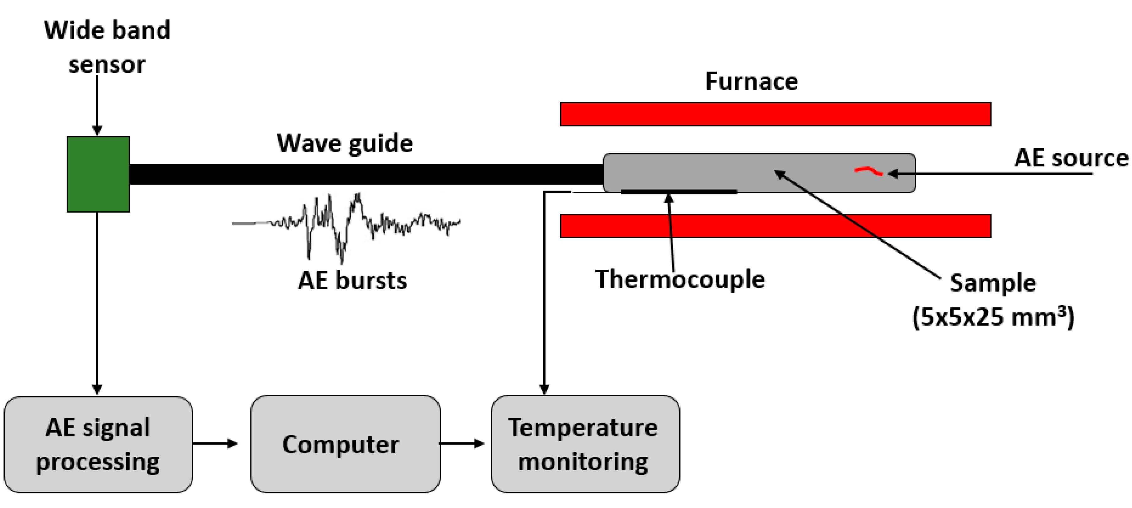
High-temperature acoustic emissions were recorded before and after thermal shocks during three consecutive thermal cycles (from room temperature up to 1300 °C and return, heat and cooling slope: 5 °C.min−1, HT 30 min dwell, RT 60 min dwell between cycle) in order to follow the evolution of the microstructure submitted to severe thermal strain. Figure 3 shows a scheme of the experimental AE testing device.
A broadband piezoelectric sensor µ80 (Mistras group SA, France) receives signals from the sample (3.5 × 3.5 × 25 mm3) via an alumina waveguide. The signals amplified were then processed using a MISTRAS 2001 (Mistras group SA, France) acquisition device and treated thanks to the NOESIS software.
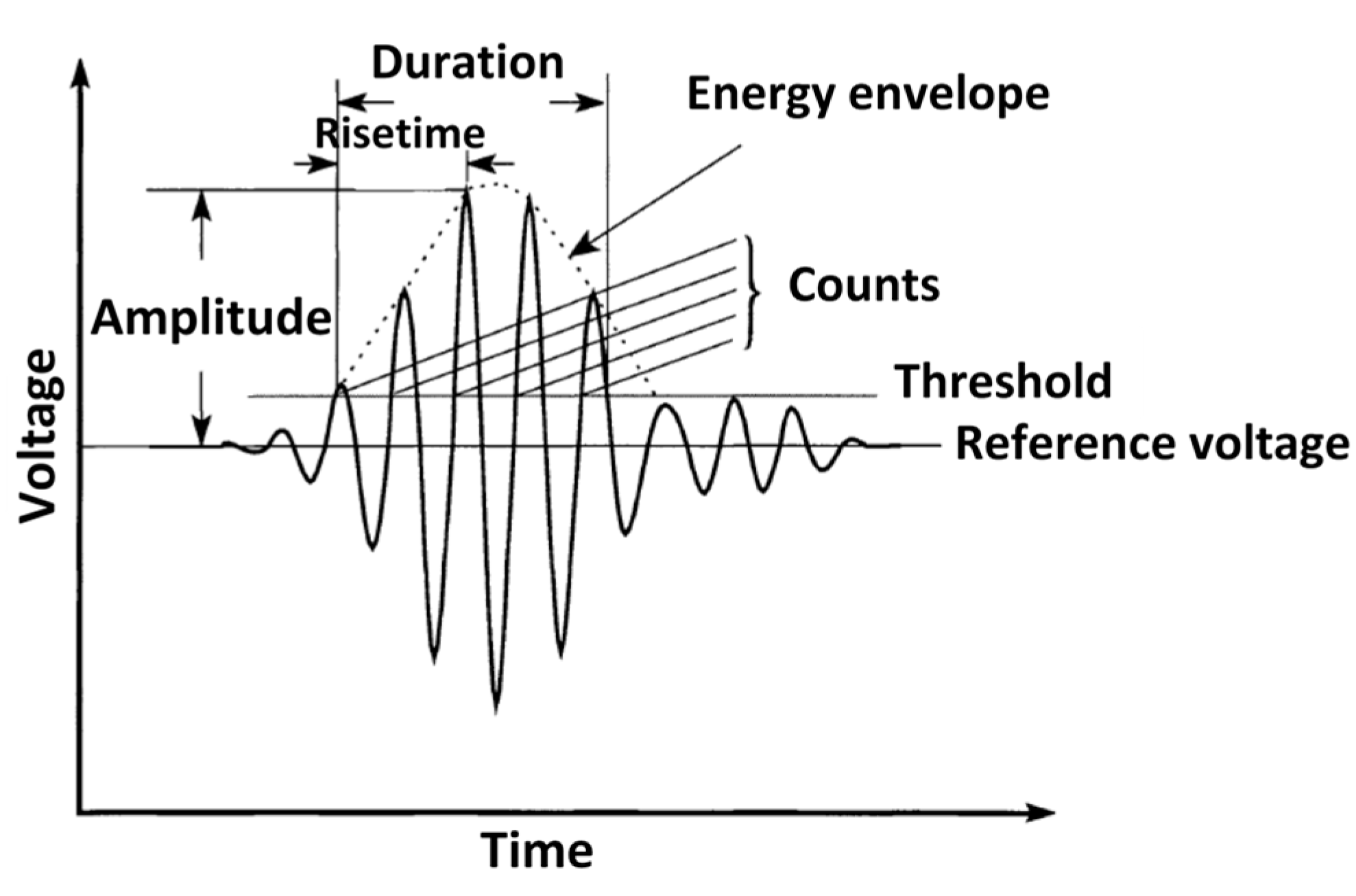
The elastic waves emitted are initially volume ones that can be longitudinal (pressure) or transverse (shear) waves but are subjected to mode conversions according to the geometry of the sample. The combination of these different modes at a given time provides a transient vibration in the form of a set of signals. The characteristics of each wave (hit shape parameters; Figure 4), such as amplitude, duration, number of counts, the absolute energy and the time, make it possible to obtain the information necessary to identify and characterise the phenomena that occur in the material during testing.

3. Results and Discussion

3.1. Microstructural Study

SEM micrographs of etched samples before thermal shock are presented in Figure 5. It is possible to observe that the sample without the addition of zircon (M1) presents a microstructure composed of mullite and also exhibits a high porosity. Microscopic observations revealed that in the samples M2 and M3, there are an enrichment in zirconia crystals distributed in the mullite matrix. It is obvious in the micrographies that the porosity of the composite decreases when the alumina and zircon proportions used in the preparation of the material increase.
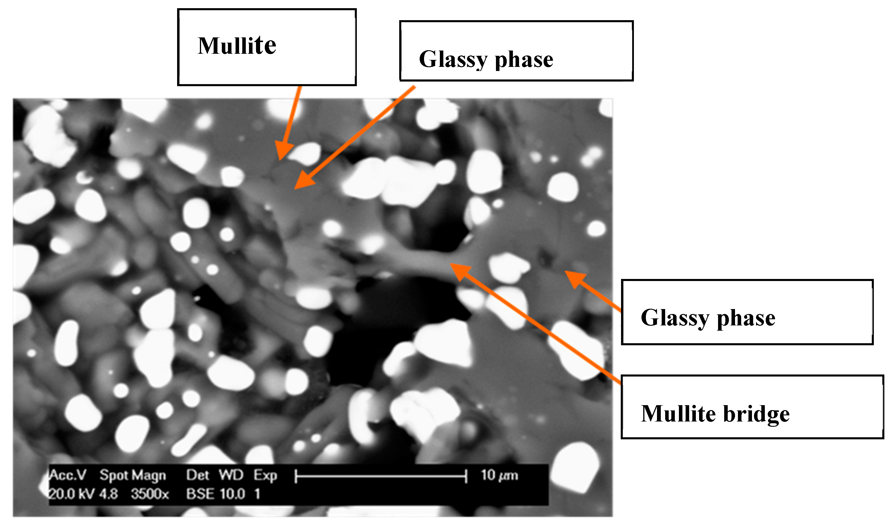
Samples M2 and M3 present some areas where the zirconia crystals are limited and very small compared to the other crystals distributed in the composite (red circle in Figure 5c). These zones consist of a crystalline network of mullite with conglomerates of small granular crystals of alumina. The presence of these alumina crystals shows an incomplete reaction with the vitreous phase derived from the reaction between the andalusite and the zircon to form secondary mullite. However, some authors [12,18,19] report that these small crystals of alumina tend to combine closely with mullite at high temperatures, giving the material a better mechanical performance. The presence of SiO2 (vitreous phase) was also identified in the microstructure of the mullite-zirconia composites, as shown in Figure 6. It is possible to observe the binding mechanism like a bridge between the crystals. This phenomenon can be very useful for enhancing the mechanical behaviour of these composites
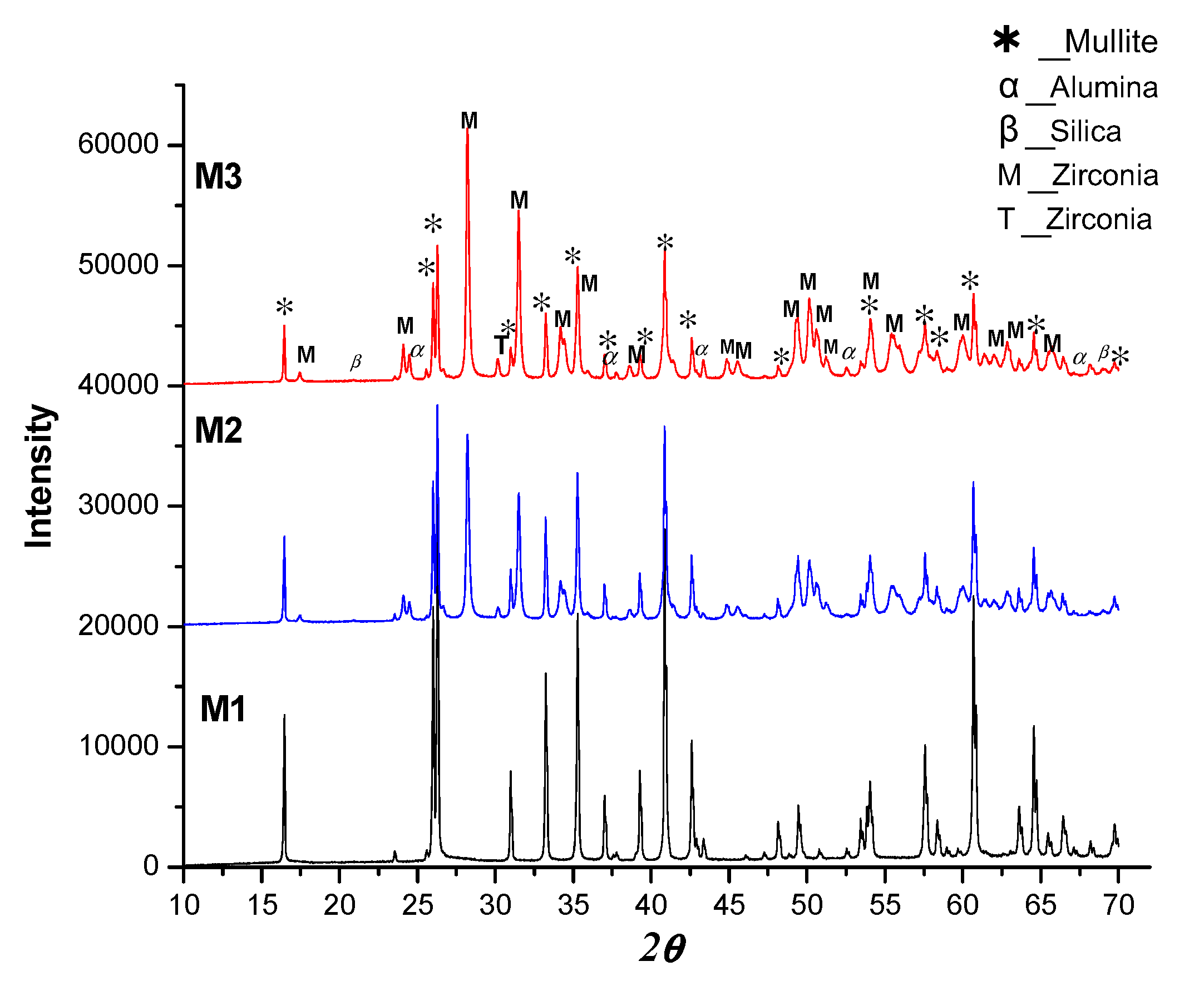
XRD analysis allowed the identification of the phase distribution in the M1, M2 and M3 samples. Table 2 presents the results obtained from XRD measurements and Rietveld refinements using boron nitride BN as an internal standard.
Mullite is the predominant phase in all samples (Figure 7, Table 2). According to the different compositions, the formation of primary mullite was attributed to the mullitisation of andalusite and the formation of secondary mullite to the reaction of alumina with the liquid phase rich in silica or vitreous phase. The results indicate that the conditions of preparation and sintering of the samples allow a complete mullitisation of andalusite.
For M2 and M3 samples, one can see that the zirconia is mainly in its monoclinic phase. However, small amounts of quadratic phase zirconia can be observed, indicating that the martensitic transformation of zirconia was not complete. This effect may be due to the presence of impurities. The amount of amorphous phase present in the structure of the sample increases considerably in M3, which is attributable to the use of a greater proportion of zircon during its fabrication. We’ll see later that this fact plays an important role in the mechanical properties. Additionally, the results obtained from Archimedes’ density technique show that the open porosity change almost linearly with the zirconia content (Figure 8). A decrease in porosity is observed as the amount of zirconia in the samples increases.
This decrease in porosity may be due to the amorphous phase generated during the decomposition of zircon. The formation of this vitreous phase can improve the densification by sintering in liquid phase [10,13,19,20,21]. It is also likely that the zirconia particles fill the gaps in the microstructure of the material. Another hypothesis to explain the reduction of porosity refers to the amount of alumina used to make the material. In fact, when the amount of alumina in the starting mixture is greater, the probability of having a reaction between it and the liquid phase to form a secondary mullite increase, which makes it possible to obtain a denser material [12]. After thermal shock, the porosity of the samples tends to increase. This may be due to the formation of cracks in the material after thermal shock. However, the difference in porosity after three and five thermal shocks is not significant (Figure 8). On the contrary, the porosity after the thermal shock for M1 mullite tends to decrease, but also after three and 5 shocks, the change in porosity is not very significant either. In this case, it is possible that during the holding of temperature at 1200 °C before making the thermal shock, the formation of secondary mullite occurred (Figure 6). For refractory applications, it is important to control the open porosity of the material, since penetration of corrosive agents can occur; however, the absence of porosity reduces the thermal shock performance since the material would not be able to adapt easily to the deformations generated by the severity of the thermal shock.

3.2. Mechanical and Thermomechanical Behaviour

3.2.1. Elastic properties

In Table 3, one can notice that the addition of zirconia into the microstructure of a mullite refractory significantly increases the Young’s modulus (E) of the material after sintering. The Young’s modulus of M2 sample is significantly larger (136.4 GPa) than in the sample without zirconia (M1) (91.5 GPa). This illustrates the fact that the presence of zirconia contributes to improve mechanical properties. This increase in value could also be attributed to the formation of secondary mullite that acts as a bridge between phases in the microstructure, as can be seen in the SEM images (Figure 6).
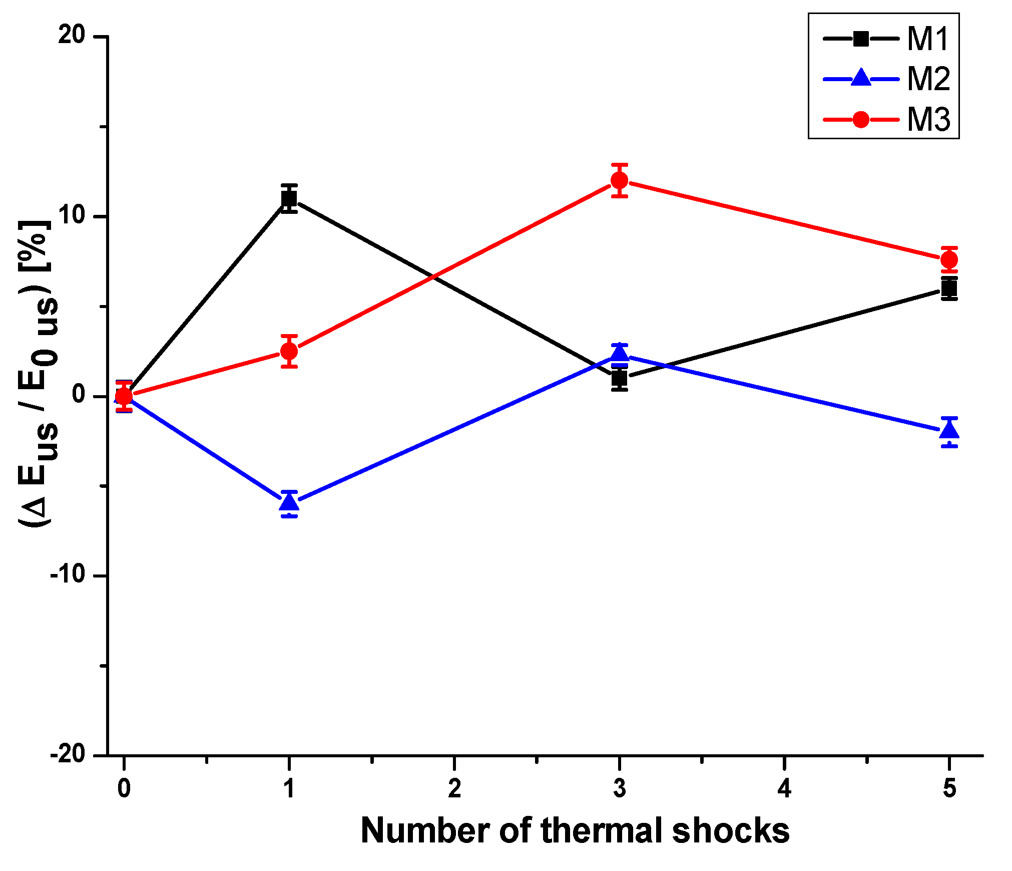
Another observation can be made. Although the M3 sample has the lowest porosity (Figure 8), E is smaller than M2. This decrease can be attributed to M3 having a greater proportion of amorphous phase (Table 2) in its structure, logically reducing the value of E. However, the Young’s moduli of M2 and M3 are superior to that of M1 one, even after having been submitted to three thermal shocks (Table 3, Figure 9). It is likely that this is associated with the repetition of the martensitic transformation Q-M (quadratic in monoclinic) which could occur during thermal shocks between temperatures of 750 °C and 500 °C [10,13]. As these samples have a considerable amount of zirconia in their structure, they can more easily block the propagation of the diffuse microcracks network and, therefore, improve their thermal shock performances.

3.2.2. Damage Behaviour (before Thermal Shock)

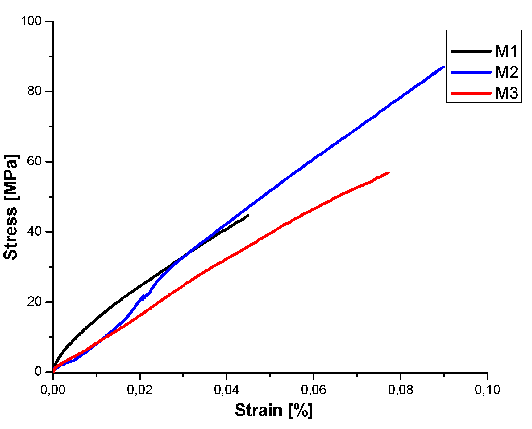
Four points bending tests coupled with AE monitoring were carried out to investigate the mechanical behaviour of the samples (5 tests for each) (Figure 10). The AE technique makes it possible here to follow the evolution of the microstructural changes, in this case the damage within the material, during the test.
The observation of this figure clearly shows how the addition of zirconia modifies and improves the bending behaviour or M2 and M3 composites compared to M1 mullite sample. If one focuses on M1 bending curve evolution (Figure 11a), we can notice that after a limited non-linear domain (from 0 to 0.01% strain) (Figure 10), the behaviour is linear elastic like illustrating the fragile characteristic of this sample.
For M2 and M3 samples (Figure 11b,c), the behaviour is significantly different. One can observe that the strain-to-rupture values of these two composites are strongly increased (+100% for M2 and +77% for M3). In the same way, a notable increase in maximal strength values are noticed (+100% for M2 and +43% for M3). These facts illustrated the ability of the zirconia grains to play a major role in the evolution of the microcracks network. As already noticed, the content of alumina in the samples favours the formation of secondary mullite that improves the interconnection between the grains. This could induce that the fracture mechanism for the material changes from intergranular to a combination of two mechanisms, transgranular and intergranular ones [9] significantly improves the flexural properties (strength and strain-to-rupture) of the samples. The glassy phase can also contribute to this interconnection between grains and therefore improve the mechanical performances. However, an excess of this amorphous phase can reduce the global mechanical performance (maximal strength and strain-to-rupture) [9], as one can see here for the M3 composite (Figure 11c).
If one looks at the AE results recorded during the bending tests, some interesting remarks can be made:
  • Firstly, the AE activity (number of hits) increases with the amount of zirconia grains,
  • The chronology of AE events occurrence is different between mullite sample (M1) and zirconia composites (M2 and M3).
To support these observations, some remarks can be made. Regarding the M1 sample in Figure 11a, a slight AE activity begins at an early stage of the limited non-linear domain (from 0 to 0.01% strain). This fact is most probably related to the onset of notable damage due to microcracking propagation between porosity. After that, the stress-strain evolution remains linear up until the occurrence of a new episode of AE activity (between 40 and 50 dB of amplitude) of the material (0.04% strain). This stage is related to a new damage propagation in the material, leading to the global ruin of the sample confirmed by high amplitude AE hits (between 60 and 100 dB) at the end of the test.
For the M2 sample (Figure 11b), no AE activity is recorded before 0.045% of strain (blue vertical line in Figure 11b). After this value (corresponding to a stress of 40 MPa), a slight decrease of E (green slope lines in Figure 11b) associated with the beginning of a noticeable AE activity (in number and in amplitude) is observed. This fact traduces the propagation of microcracking affecting the solidity of the secondary mullite bridges within the material.
In the M3 composite (Figure 11c), AE activity is recorded at the very beginning of the test (ε = 0.005%) and that for a relative low stress level (σ = 30 MPa). This could be explained by the onset and propagation of diffuse microcracking with the glassy phase (highest amount for this composite: 27.5%) which filled the initial porosity of the composite. This also explains the lower value of E compared with that of M2 (116.9 and 136.4 GPa, respectively, see Table 3). After this, No AE is recording up to 0.055% of strain. For this strain level, also corresponding again to a stress level of 40 MPa, a significant fall in the sample rigidity is noticed, which is associated with a restart of the AE activity and most probably related, once more, to the propagation of microcracking affecting the integrity of secondary mullite bridges.

3.2.3. Damage Behaviour (after Thermal Shock)

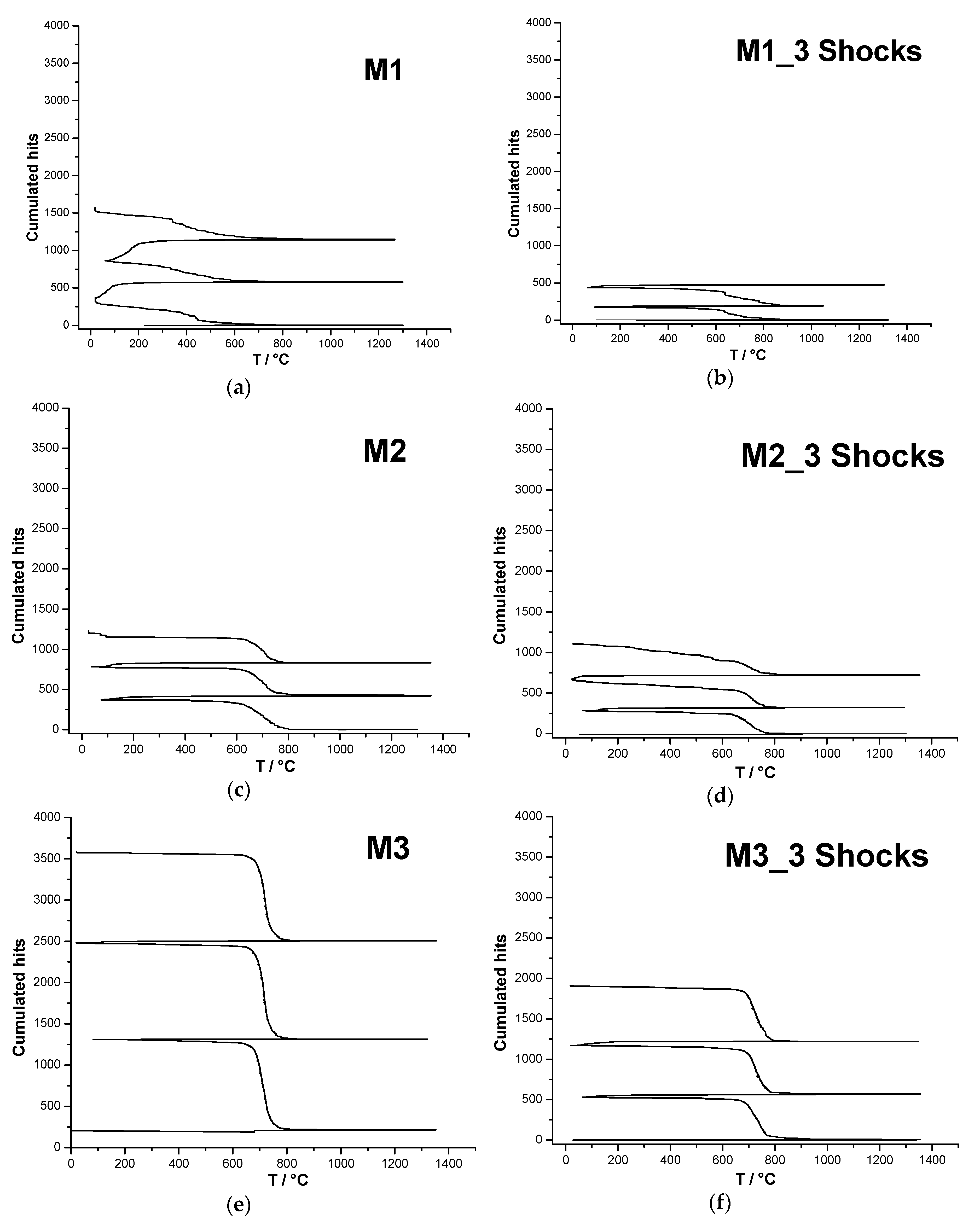
Damage behaviour after thermal shock was evaluated thanks to AE testing during thermal cycling. Figure 12 presents the results for the M1, M2 and M3 samples tested before thermal shock and after 3 consecutive thermal shocks. In these graphs, a significant difference between the test profile of the M1 sample (mullite) and those of the mullite zirconia composites (M2, M3) can be observed.
For the M1 sample without thermal shock, during the heating of the first cycle, no AE was recorded. The AE activity begins during the cooling stage in this same cycle, showing a significant increase in the hit rate, (number of hit/°C) below 600 °C. At the beginning of the second cycle, there is a significant increase in AE activity up to 100 °C, which is repeated in the third cycle. This type of behaviour could correspond, in a porous material like M1, to the opening (cooling) and closing (heating) of the diffuse microcracking network present in the microstructure. The absence of recorded AE during the first heating confirms that the materials is undamaged before the first thermal cycle. After 3 consecutive thermal shocks (Figure 12b), the sample exhibits a lower cumulated number of hits, demonstrating that the material has already endured a non-evolutive damage.
For M2 and M3 composite samples, either before and after thermal shocks (Figure 12c–f;), and contrary to the M1(mullite) sample, there is no significant AE during heating in any thermal cycle. However, an increase, both in the accumulated hits and in the hit rate, is observed, which is related to the amount of zirconia in the composite. In addition, it can be noticed that this sudden evolution of hit rate systematically occurs around 800 °C up to 600 °C (at lower temperature for the M1 (mullite) sample; 500 °C to 100 °C). Several hypotheses can be proposed to interpret these observations:
  • The temperature range in the mullite-zirconia composites, where a sudden increase in acoustic activity is observed, could correspond to the temperature range of the martensitic transformation of zirconia during cooling. A previous study on high zirconia content refractories [22] showed that this activity could be related to the possible movement of the crystallographic variants present in zirconia grain at the time of transformation. The author also showed that this expansive transformation generates significant microcracking episodes, especially in the vitreous phase present at the ZrO2 dendrite interface. However, since this transformation is reversible, an acoustic activity during heating should have been recorded. The absence of signals during heating is explained by the low viscosity of the glassy phase at high temperature that acts as a low pass filter of the emitted signals, in this case high frequency signals.
  • The higher value of accumulated hits (both before and after three thermal shocks) for M3 is most probably related to the higher amount of glassy phase present in the material. Unfortunately, we could not quantify the amount of secondary mullite after thermal shocks for the M3 samples, which would have most probably reinforced the above argumentation. However, a higher amount of zirconia particles is also noticed.
  • The explanation for the difference in accumulated hit level (especially for M3; Figure 12e,f) before and after thermal shocks, could be associated with the following. The consecutive aspect of thermal shock in a composite containing the highest silica glassy phase amount leads to the possibility of the multiplication of secondary mullite bridges, consequently opposing the propagation of the microcracking induced by the thermal expansion and, in fact, generating less acoustic emission.
To summarise, and considering the previous hypotheses, the recorded AE during tests are very likely generated by a combination of phenomena. In chronological order, the signals detected initially during cooling could correspond to the early movement of the crystallographic variants in zirconia grain, and then the following recorded signals could be generated by the microcracking of the glassy phase induced by the expansion of zirconia particles during the martensitic transformation.

4. Conclusions

In this study, it has been shown that the elaborated mullite zirconia composites have higher mechanical properties than the mullite material either before or after consecutive thermal shocks. Moreover, a systematic (and quite surprising the first time) increase of the Young’s modulus (E) values for the composites after several thermal shocks has been reported. After a rigorous and deep analysis supported by microstructural techniques, it appears that this increase could be closely related to the formation of secondary mullite resulting from the reaction between the alumina and the high silica glassy phase amount present in material that acts as a bridge between the phases and thus improves the mechanical properties of the composites. This vitreous phase also has a very important effect on the densification of the material by decreasing the porosity. However, the results of the four points bending tests indicate that an excessive amount of glassy phase can significantly affect the mechanical properties. That is why the quantity of raw materials proposed for the manufacture of these refractories, and above all the amount of zircon, should be carefully considered. It is obvious that the coupling of the Acoustic Emission technique to bending tests or to thermal cycling testing is of great interest for the interpretation of test results.
For bending tests performed on non-thermal shocked samples, AE clearly indicated (chronologically speaking) that the acoustic activity could be related to several sources:
  • Microcracking onset and propagation in mullite material for low stress-low strain level,
  • Microcracking onset and propagation in zirconia-mullite composites for a higher level of stress and strain (increase of mechanical properties).
  • Detection at an early stress-strain level of microcracking in glass rich composite sample (M3), where a greater amount of amorphous phase generated an increase in AE.
AE recorded at high temperature, during successive thermal cycles and on samples either thermal shocked or not, made it possible to propose a more accurate interpretation of the chronology of the microstructural changes that take place during the thermal cycles. The results indicate that the acoustic activity during repeated cycles at high temperature could be generated by two consecutive phenomena:
  • The movement of crystallographic variants due to the martensitic transformation (M-T) to the cooling of zirconia particles.
  • Cracks induced by expansion in the amorphous phase surrounding the zirconia particles.
High-temperature acoustic emission tests for samples before thermal shocks show that this microcracking increases when the zirconia content increases. On the other hand, this activity is reduced in composite samples (especially silica glassy phase rich one) subjected to several consecutive thermal shocks, which demonstrates the major role played by the secondary mullite bridging phenomenon in the improvement of thermal shock performances of such refractory composites.

Author Contributions

Investigation, L.A.M. and M.-L.B.; Project administration, T.C.; Supervision, T.C. and J.P.; Writing—original draft, T.C. and L.A.M.; Writing—review & editing, T.C.

Funding

This research received no external funding.

Conflicts of Interest

The authors declare no conflict of interest.

References

  1. Salmang, H.; Scholze, H.; Telle, R. Keramik, 7th ed.; Telle, R., Ed.; Springer: Berlin/Heideberg, Germany, 2007. [Google Scholar]
  2. Boch, P.; Giry, J.P. Preparation and properties of reaction-sintered mullite-ZrO2 ceramics. Mat. Sci. Eng. 1985, 71, 39–48. [Google Scholar] [CrossRef]
  3. Cambier, F.; Baudin, C.; La Lastra, D.; Pilate, P.; Leriche, A. Formation of microstructural defects in mullite-zirconia and mullite-alumina-zirconia composites obtained by reaction-sintering of mixed powders. Br. Ceram. Trans. J. 1984, 83, 196–200. [Google Scholar]
  4. Di Rupo, E.; Anseau, M.R. Solid state reactions in the ZrO2–SiO2–αAl2O3 system. J. Mater. Sci. 1980, 15, 114–118. [Google Scholar] [CrossRef]
  5. Rendtorff, N.; Garrido, L.; Aglietti, E. Mullite–zirconia–zircon composites: Properties and thermal shock resistance. Ceram. Int. 2009, 35, 779–786. [Google Scholar] [CrossRef]
  6. Rendtorff, N.; Garrido, L.; Aglietti, E. Thermal shock behaviour of dense mullite-zirconia composites obtained by two processing routes. Ceram. Int. 2008, 34, 2017–2024. [Google Scholar] [CrossRef]
  7. Hamidouche, M.; Bouaouadja, N.; Osmani, H.; Torrecillias, R.; Fantozzi, G. Thermomechanical behaviour of mullite-zirconia composite. J. Eur. Ceram. Soc. 1996, 16, 441–445. [Google Scholar] [CrossRef]
  8. Rendtorff, N.; Garrido, L.; Aglietti, E. Effect of the addition of mullite-zirconia to the thermal shock behavior of zircon materials. Mater. Sci. Eng. A 2008, 498, 208–215. [Google Scholar] [CrossRef]
  9. Chan, C.F.; Ko, Y.C. Effect of Cr2O3 on slag resistance of Al2O3-SiO2 refractories. J. Am. Ceram. Soc. 1992, 75, 2857–2861. [Google Scholar] [CrossRef]
  10. Bouchetou, M.L.; Poirier, J.; Joubert, O.; Weissenbacher, M. A new raw material: A sintered zirconia-mullite refractory composite. In Proceedings of the 60th International colloquium on refractories, Aachen, Germany, 18 October 2017; 2017; pp. 162–165. [Google Scholar]
  11. Walaan, T.; Psiuka, B.; Kubackib, J.; Steca, K.; Podwórnya, J. Mullitisation process of andalusite concentrates—role of natural inclusions. Ceram. Int. 2014, 40, 5129–5136. [Google Scholar]
  12. Xu, X.; Li, J.; Wu, J.; Tang, Z.; Chen, L.; Li, Y.; Lu, C. Preparation and thermal shock resistance of corundum-mullite composite ceramics from andalusite. Ceram. Int. 2017, 43, 1762–1767. [Google Scholar] [CrossRef]
  13. Bouchetou, M.L.; Poirier, J.; Morales, L.A.; Chotard, T.; Joubert, O.; Weissenbacher, M. Synthesis of an innovative zirconia-mullite raw material sintered from andalusite and zircon precursors and an evaluation of its corrosion and thermal shock performance. Ceram. Int. 2019, 45, 12832–12844. [Google Scholar] [CrossRef]
  14. Shull, P.J. Nondestructive Evaluation: Theory, Techniques, and Applications; CRC press: Boca Raton, FL, USA, 2002. [Google Scholar]
  15. Integrity Diagnostics. Introduction to Acoustic Emission. Available online: http://www.idinspections.com/acoustic-emission-phenomenon/ (accessed on 31 March 2019).
  16. Kaphle, M.R. Analysis of Acoustic Emission Data for Accurate Damage Assessment for Structural Health Monitoring Applications. Ph.D. Thesis, Queensland University of Technology, Brisbane City, Australia, 2012. Available online: https://eprints.qut.edu.au/53201/ (accessed on 20 November 2018).
  17. Finlayson, R.D.; Friesel, M.; Carlos, M.; Cole, P.; Lenain, J.C. Health monitoring of aerospace structures with acoustic emission and acousto-ultrasonics. Insight-Wigston then Northampton 2001, 43, 155–158. [Google Scholar]
  18. Pannhorst, W.; Schneider, H. The high-temperature transformation of andalusite (A12SiO5) into 3/2-mullite (3A12O32SiO2) and vitreous silica (SiO2). Miner. Mag. 1978, 42, 195–198. [Google Scholar] [CrossRef]
  19. Aksel, C. Mechanical Properties of Alumina-Mullite-Zircon Refractories. In Key Engineering Materials; Trans Tech Publications: Stafa-Zurich, Switzerland, 2004; Volume 264–268, pp. 1791–1794. [Google Scholar] [CrossRef]
  20. Pooladvand, H.; Mirhadi, B.; Baghshahi, S.; Souri, A.R.; Arzani, K. Effects of alumina and zirconia addition on transformation of andalusite to mullite. Adv. Appl. Ceram. 2009, 108, 389–395. [Google Scholar] [CrossRef]
  21. Aksel, C.; Riley, F.L.; Konieczny, F. The Corrosion Resistance of Alumina-Mullite-Zircon Refractories in Molten Glass. In Key Engineering Materials; Trans Tech Publications: Stafa-Zurich, Switzerland, 2004; Volume 264–268, pp. 1803–1806. [Google Scholar] [CrossRef]
  22. Patapy, C. Comportement thermomécanique et transformations de phase de matériaux réfractaires électrofondus à très haute teneur en zircone. Ph.D. Thesis, Université de Limoges, Limoges, France, 2010. [Google Scholar]
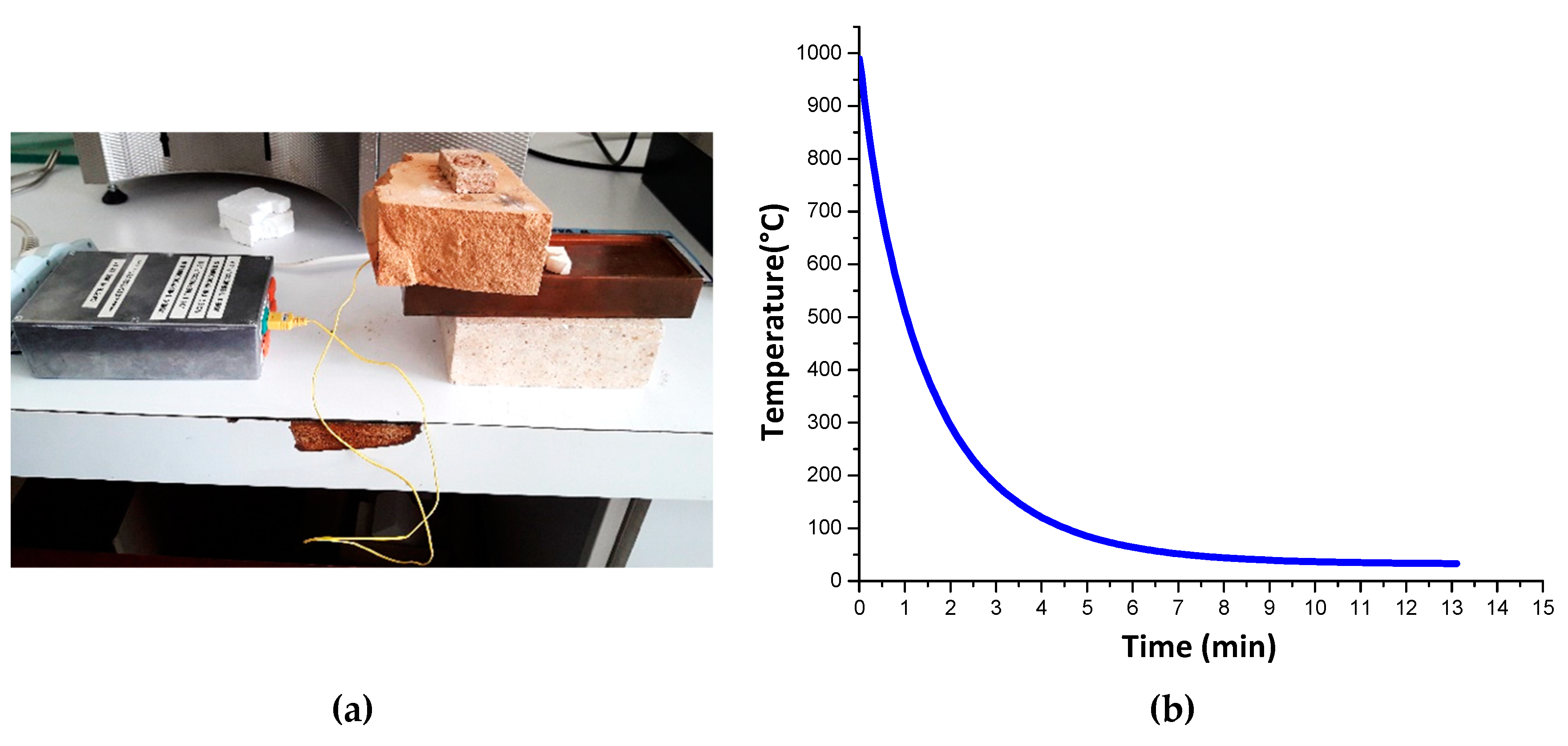
Figure 1. Measurement method of the cooling rate during thermal shock: (a) device for measuring the temperature with a thermocouple; (b) cooling curve.
Ceramics 02 00046 g001
Figure 2. Experimental configuration for AE damage monitoring during bending test.
Ceramics 02 00046 g002
Figure 3. Experimental HT AE monitoring device and configuration.
Ceramics 02 00046 g003
Figure 4. Hit shape characteristics.
Ceramics 02 00046 g004
Figure 5. Microstructure of the samples before thermal shock: (a) M1; (b) M2; (c) M3.
Ceramics 02 00046 g005
Figure 6. Bonding between secondary mullite and the crystals of M2 microstructure.
Ceramics 02 00046 g006
Figure 7. XRD spectra of the composite samples.
Ceramics 02 00046 g007
Figure 8. Evolution of open porosity before and after successive thermal shocks for M1, M2 and M3 samples.
Ceramics 02 00046 g008
Figure 9. Normalized evolution of ultrasonic measured Young’s modulus of samples before and after thermal shocks.
Ceramics 02 00046 g009
Figure 10. Four points bending stress-strain evolution for sample before thermal shock.
Ceramics 02 00046 g010
Figure 11. Details for bending test and coupled AE results: (a) M1; (b) M2; (c) M3.
Ceramics 02 00046 g011
Figure 12. AE testing during thermal cycling of samples: (a) M1 without thermal shock, (b) M1 after 3 thermal shocks, (c) M2 without thermal shock, (d) M2 after 3 thermal shocks, (e) M3 without thermal shock, (f) M3 after 3 thermal shocks.
Ceramics 02 00046 g012
Table 1. Composition of samples.
Component/SampleD50 (µm)M1M2M3
Andalusite (% weight)569.4928.465.05
Alumina (% weight)0.830.5139.3544.40
Zircon (% weight)1.3032.1950.55
Solid fraction (Ø)NANANANA
Table 2. Phase distribution in M1, M2 and M3 samples.
Phase Quantification (Rietveld)M1M2M3
Mullite (%)96.763.742.5
Alumina (α) (%)3.31.95.5
Monoclinic Zirconia (M) (%)-16.723.4
Tetragonal Zirconia (T) (%)-0.51.1
Quartz (%)-0.9-
Amorphous phase (%)-16.327.5
Table 3. Young’s moduli for samples before (Mx) and after (y) thermal shocks (Mx_yS), measured by ultrasonic pulse echography.
SampleM1M1_1SM1_3SM1_5S
E (GPa)91.5103.092.497.9
SampleM2M2_1SM2_3SM2_5S
E (GPa)136.4127.8139.6133.5
SampleM3M3_1SM3_3SM3_5S
E (GPa)116.9120.0132.5126.6