Article

Optimization of Water Tank Shape in Terms of Firefighting Vehicle Stability

by
Jaroslav Matej
* and
Michaela Hnilicová
Department of Mechanics, Mechanical Engineering and Design, Faculty of Technology, Technical University in Zvolen, T.G. Masaryka 24, 96001 Zvolen, Slovakia
*
Author to whom correspondence should be addressed.
Appl. Syst. Innov. 2025, 8(4), 112; https://doi.org/10.3390/asi8040112
Submission received: 25 June 2025 / Revised: 28 July 2025 / Accepted: 1 August 2025 / Published: 11 August 2025

Abstract

In this work we present the shape optimization of a 2000 L water tank placed behind the rear axle of a forestry skidder. The main criterion is the static stability of the vehicle. The purpose of the research is to decrease the impact of the tank on stability of the vehicle. The stability is determined in the form of distances of vectors of a stability triangle and a gravity vector. The tank is divided into small elements and their impact on stability is evaluated independently. Then, the gravity vector, placed in the center of gravity of the vehicle with the tank, combines the gravities of the vehicle and the tank composed of as many elements as required for the desired volume. The Python 3.13 programming language is used to implement the solution. The results for various shapes of the tank are displayed in the form of heatmaps. A slope angle of 20 degrees is used for the analysis. The results show that the longitudinal or lateral stability can be improved by shape modifications of the tank. The most interesting output is the final shape of the tank that improves terrain accessibility of the vehicle. The optimization method is universal and can also be used for different vehicles, tank placements and also auxiliary devices added in general positions.

1. Introduction

Rising temperatures and prolonged periods of dryness caused by climate change significantly increase the likelihood of forest fires [1]. Addressing these fires requires intensified efforts and the adoption of new, or at least additional, solutions. Two critical prerequisites for effective wildfire suppression are accessibility to the affected area and the availability of sufficient water resources. Machine design and construction processes should ideally be part of a broader system aimed at achieving defined operational goals. Designers, who are tasked with determining technical and operational parameters, must strive to ensure maximum machine efficiency [2]. Today, a variety of vehicles exist that are either purpose-built or adapted for wildfire management. Most of these are single-purpose machines [3,4,5,6,7]. A fundamental aspect of effective intervention is the rapid delivery of water as close as possible to the operational area of the fire brigade. In this context, conventional forestry machinery, particularly forestry skidders, present a practical solution. Skidders offer strong capabilities in steep and rugged terrain. When fitted with firefighting accessories, especially those requiring no structural modifications, they can dramatically reduce fire response time due to their immediate availability. The firefighting adapter shown in Figure 1, when connected to a skidder, allows the transportation of water directly into wildfire zones. Introduced in 2020, this adapter was designed specifically to support firefighting in challenging forest environments [8]. Its key characteristic is a large water tank mounted significantly behind the rear axle on the skidder’s rear shield.
The stability research presented here is motivated by the novel adapter design [8] and expands upon previous investigations into its static stability [9]. The adapter, which features a 2000 L tank (Figure 1), is mounted on the LKT-81T skidder. Once positioned in an accessible area near the fire site, the tank can be refilled repeatedly via helicopter using a Bambi bucket. From an operational standpoint, a larger tank is preferable for firefighting; however, placing a large mass behind the rear axle significantly affects the stability of the machine. In earlier work [9], we examined whether placing a counterweight ahead of the front axle could compensate for the rear-mounted weight or tank. The results were not convincing enough to consider this matter resolved. Therefore, the present study focuses on analyzing how modifications to the tank’s shape influence the static stability of the machine.
Numerous methods have been developed to assess static stability in vehicles. These include designs with pivoting front or rear axles, articulated frames, and computational techniques such as the stability triangle model. The original research describing the firefighting adapter [8] does not include any form of stability analysis, despite the adapter’s unique characteristics. Nonetheless, the fundamental principles and methods used to assess vehicle stability remain broadly applicable. Gibson [10] studied the lateral stability of articulated logging tractors on sloped terrain and introduced the concept of the stability triangle and approximated center of gravity locations. Franceschetti [11] analyzed the lateral stability of narrow-track articulated tractors using an inclined plane test method. Similarly, Sierzputowski [12] employed an inclined plane platform to evaluate rollover stability in articulated vehicles, noting that a full stability assessment requires measuring critical slope angles across all platform orientations. Bołoz [13] developed a mathematical model for the stability of articulated drilling rigs using a global coordinate system fixed to the front frame. Tomašić [14] investigated force distribution during timber skidding uphill and downhill at varying slope angles. Bietresato and Mazzetto [15,16,17] constructed a large tiltable platform (15 × 15 m) capable of simulating different slope conditions, allowing vehicles to move along circular paths in a controlled environment. A turntable installed on the lower half of the platform allowed for static testing of a vehicle’s stability in all orientations. Majdan [18] measured the center of gravity in a small agricultural tractor and calculated static tipping angles according to ISO 16231-2 [19]. Mazzetto [20] examined the kinematics of an articulated tractor with a central joint using custom software developed in MATLAB. Demšar [21] created a mathematical model and simulation to analyze the static stability of an agricultural tractor. Bołoz, Kozłowski and Horak [22] created a computational model for analyzing the stability of the BEV LHD loader. To verify the theoretical model they carried out dynamic simulation tests using Autodesk Inventor Professional Dynamic Simulation module. Tianlong, Jixin and Zongwei [23] created a nonlinear dynamic model of articulated vehicles and a model of hydraulic steering system. Tota, Galvagno and Velardocchia [24] focused on analyzing the cornering behavior of articulated tracked vehicles, composed of two rigid bodies connected by a hinge and steered via articulation. They developed an 8-degree-of-freedom nonlinear mathematical model to describe the dynamic behavior during turning maneuvers. Reński [25] studied rollover crashes. He described method of calculation of the course of rollover in time domain and investigated the influence of the height the centre of gravity on the increase of the rollover angle velocity.
These studies all rely on similar physical principles for assessing vehicle stability on slopes. However, in scenarios where a vehicle must carry multiple loads positioned in different locations, these conventional methods often prove inadequate. For this reason, the methodology introduced in [9] was adopted in this study in a simplified form. This method models all possible ranges of frame articulation and vehicle positions/rotations on an inclined plane using two independent variables and presents the results in the form of heatmaps.

2. Materials and Methods

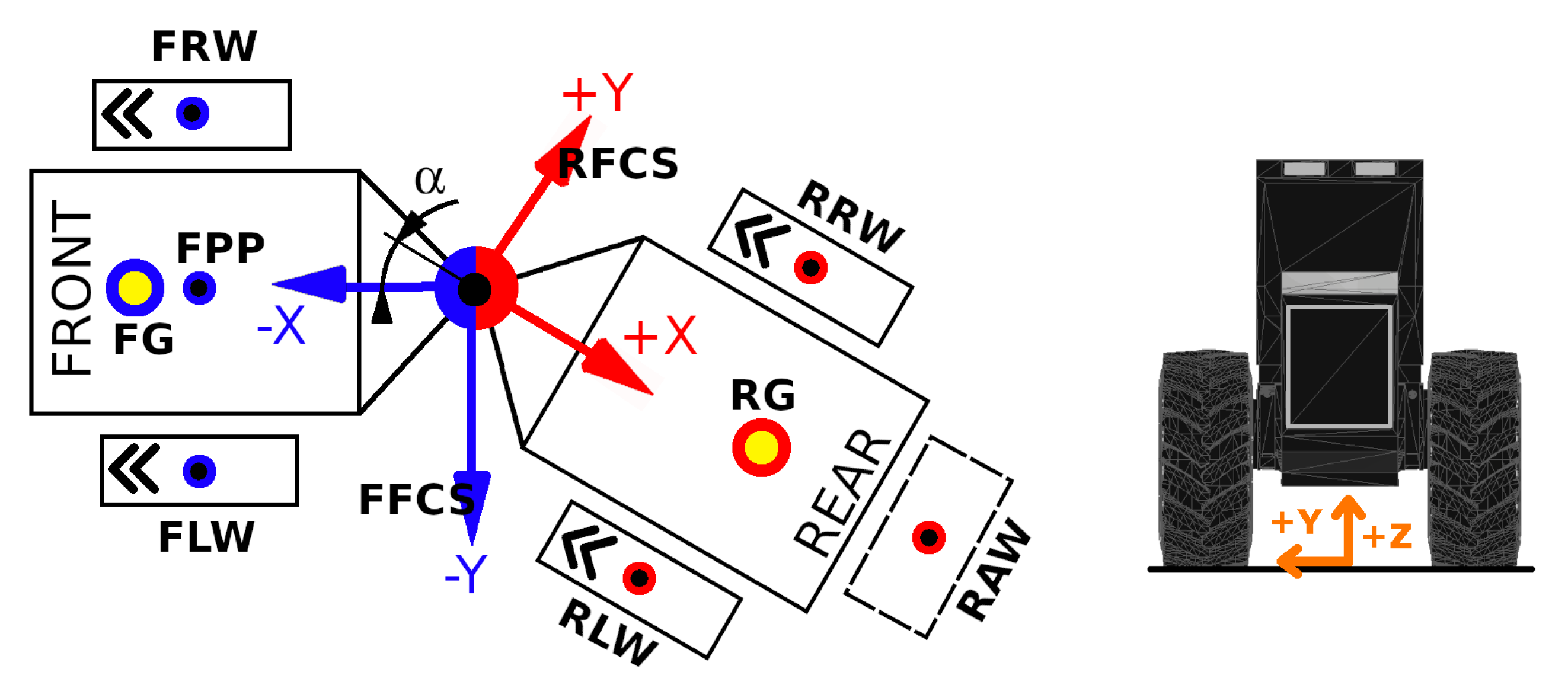
The stability evaluation method, used in this article, and introduced in [9] is grounded in the physical principle that a vehicle is statically stable if the gravity vector, originating from its center of gravity, remains within the boundaries of its stability polygon (or triangle). The stability triangle is defined by the tipping lines around which the vehicle may overturn when it loses stability. In this method, the tipping lines and the gravity vector are represented as spatial line equations. The shortest distances from the gravity vector to each side of the stability triangle are then used to determine the vehicle’s stability in its most fundamental form. To identify unstable positions, it is necessary to verify whether the gravity vector lies within the area of the stability triangle. This method calculates and visualizes these distances for all machine positions on a slope, generating plots for each of the triangle’s three sides. By employing vector-based computation and a general-purpose programming language, the method is designed to be adaptable and extensible. As such, it can be modified for future applications to other types of machinery. The entire solution has been implemented using the Python programming language, operating in a three-dimensional coordinate system. Key points on the skidder are defined by their coordinates in a local coordinate system (Figure 2). These points correspond to a simplified skidder model that approximates the geometry and parameters of the LKT-81 skidder, which is no longer in production (Table 1). This simplification includes estimated positions for the front and rear centers of gravity (FG and RG, respectively). Such an approximation is justified by the primary objective of the study, which is to analyze and compare the effects of various modifications of the water tank shape on the static stability of the machine.
The stability triangle is created by lines ( l 1 _ z , l 2 _ z , l 3 _ z ) as shown in Figure 3. The gravity vector is placed in the center of gravity labeled T. It is also represented as a line that we used to compute distances to the lines of the stability triangle.
Lines in standard vector form were used as follows:
( x , y , z ) = ( x 0 , y 0 , z 0 ) + t ( a , b , c )
where
( x 0 , y 0 , z 0 ) —a point on a line (e.g., start point),
( x , y , z ) —another point on a line (e.g., end point),
t—a parameter describing a particular point on a line,
( a , b , c ) —directional vector of a line.
Distances between lines, mainly between the gravity vector and tipping lines of the stability triangle (Figure 3) were determined using equation [26]:
d = ( V 1 x V 2 ) P 1 P 2 V 1 x V 2 = ( q 1 r 2 q 2 r 1 ) a 12 + ( r 1 p 2 r 2 p 1 ) b 12 + ( p 1 q 2 p 2 q 1 ) c 12 ( q 1 r 2 q 2 r 1 ) 2 + ( r 1 p 2 r 2 p 1 ) 2 + ( p 1 q 2 p 2 q 1 ) 2
where
p 1 = x 1 x 1 0 ; q 1 = y 1 y 1 0 ; r 1 = z 1 z 1 0
p 2 = x 2 x 2 0 ; q 2 = y 2 y 2 0 ; r 2 = z 2 z 2 0
a 12 = x 1 0 x 2 0 ; b 12 = y 1 0 y 2 0 ; c 12 = z 1 0 z 2 0
and
x 1 , y 1 , z 1 —are x , y , z coordinates of an end point of the first line (see Equation (1))
x 2 , y 2 , z 2 —are x , y , z coordinates of an end point of the second line
x 1 0 , y 1 0 , z 1 0 —are x , y , z coordinates of a start point of the first line
x 2 0 , y 2 0 , z 2 0 —are x , y , z coordinates of a start point of the second line
All the distances are always positive (Equation (2)). To detect whether the gravity vector remains within the boundaries of its stability polygon, we used the crossing number algorithm. Its essence is that if a point is on the outside of the polygon, the ray from the point in any fixed direction will intersect its edge an even number of times. An odd result means the point is on the inside of the polygon [9].
As mentioned above, the center of gravity T (Figure 3) is composed of the center of gravity of the machine and the tank, or other components. All the gravity vectors create a list. The final gravity vector position T was computed in successive steps where any two vectors were removed from the list, and their center of gravity was inserted back to the list [9]. This way, the last vector in the list represents the final gravity vector T.
Using Equation (2), stability is obtained for only one tractor position on the slope. To obtain comprehensive information about static stability, the calculations were solved for a range of input parameters, where
  • Slope angle β was a constant,
  • Frame’s articulation α was variable in interval of 45 ; 45 ,
  • Skidder’s rotation γ on a slope was variable in interval of 0 ; 359 [9].
This approach enables the assessment of the static stability of the firefighting equipment configuration on a predefined slope, taking into account different positions/rotations on the inclined surface. It allows for the evaluation of how the combination of frame articulation angle α and rotational orientation γ affects stability, quantified by the distance from the gravity vector to the tipping lines. In general, wheeled skidders are not recommended to operate on slopes steeper than 40%, although this threshold varies depending on the load. For example, a skidder carrying a 3-tonne load is typically limited to slopes ranging from −34% (descending) to +39% (ascending). For a 4-tonne load, the safe range narrows to between −35% and +30% and for a 5-tonne load, it is further reduced to between −41% and +11% [27]. Based on these considerations, a slope angle of 20 (equivalent to 36.4 % ) was selected for the simulations. To visualize the results, the Python libraries matplotlib.pyplot and pyvista were utilized. The contourf function was employed to generate contour plots representing stability, while pyvista was used for three-dimensional visualization of the optimized tank shapes.
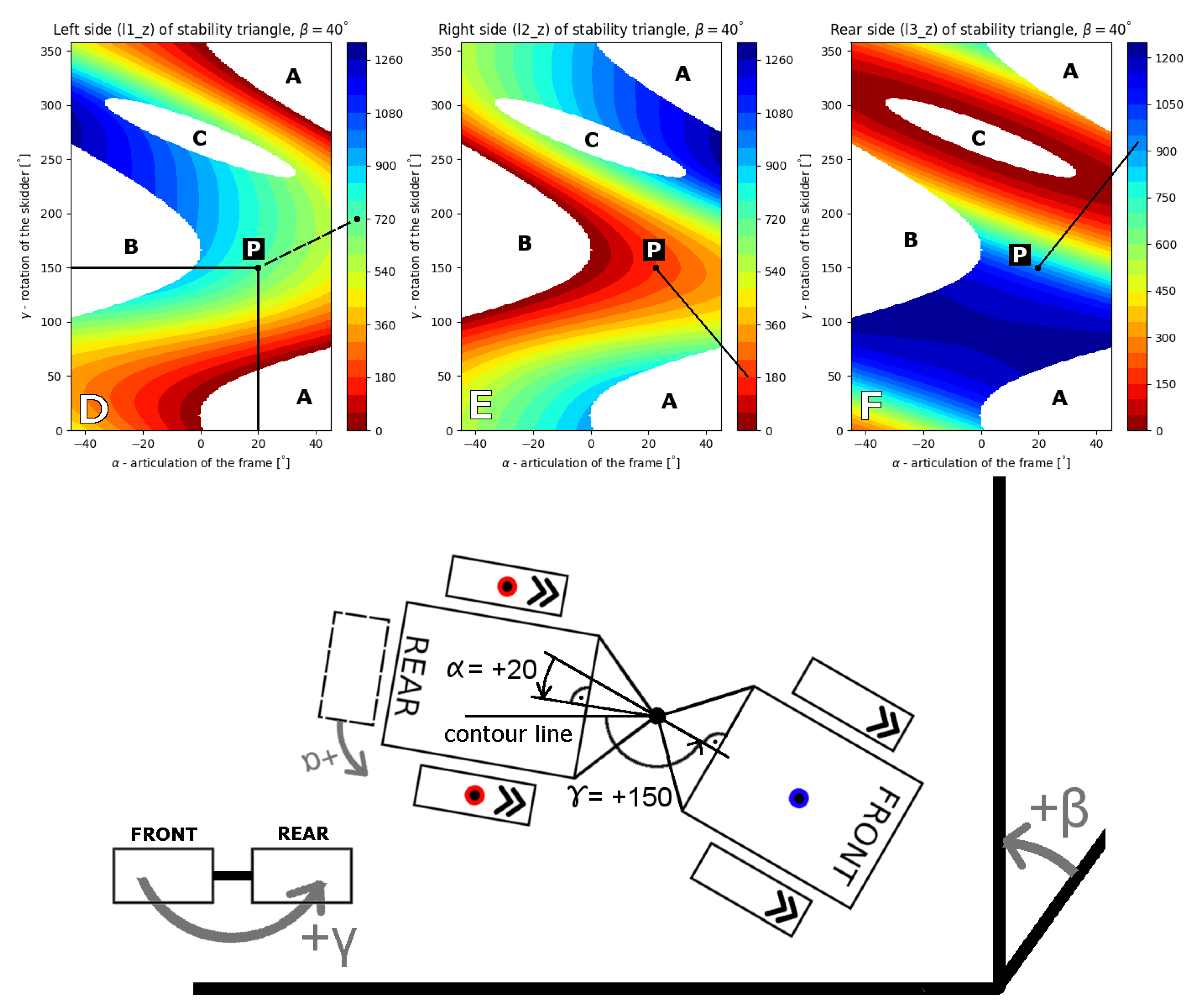
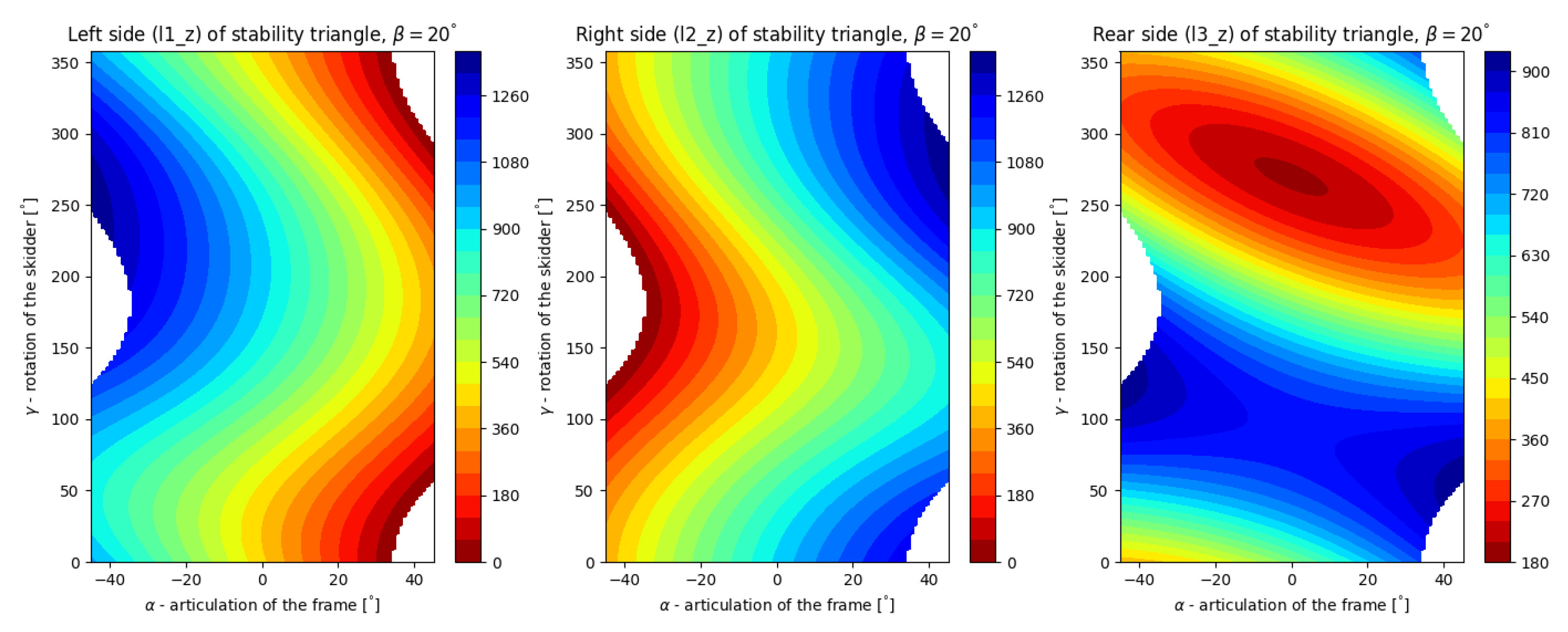
An example of the plot is shown in Figure 4. A point on a plot displays just one position of the machine. Its actual position, illustrated below the plot, may be expressed by the point P in Figure 4. To obtain this position, the skidder was placed at the default position (front part facing toward 9 o’clock, on a contour line, as shown in Figure 3, α = 0), then rotated by the angle of 150 , then the rear frame was articulated by the angle of 20 .
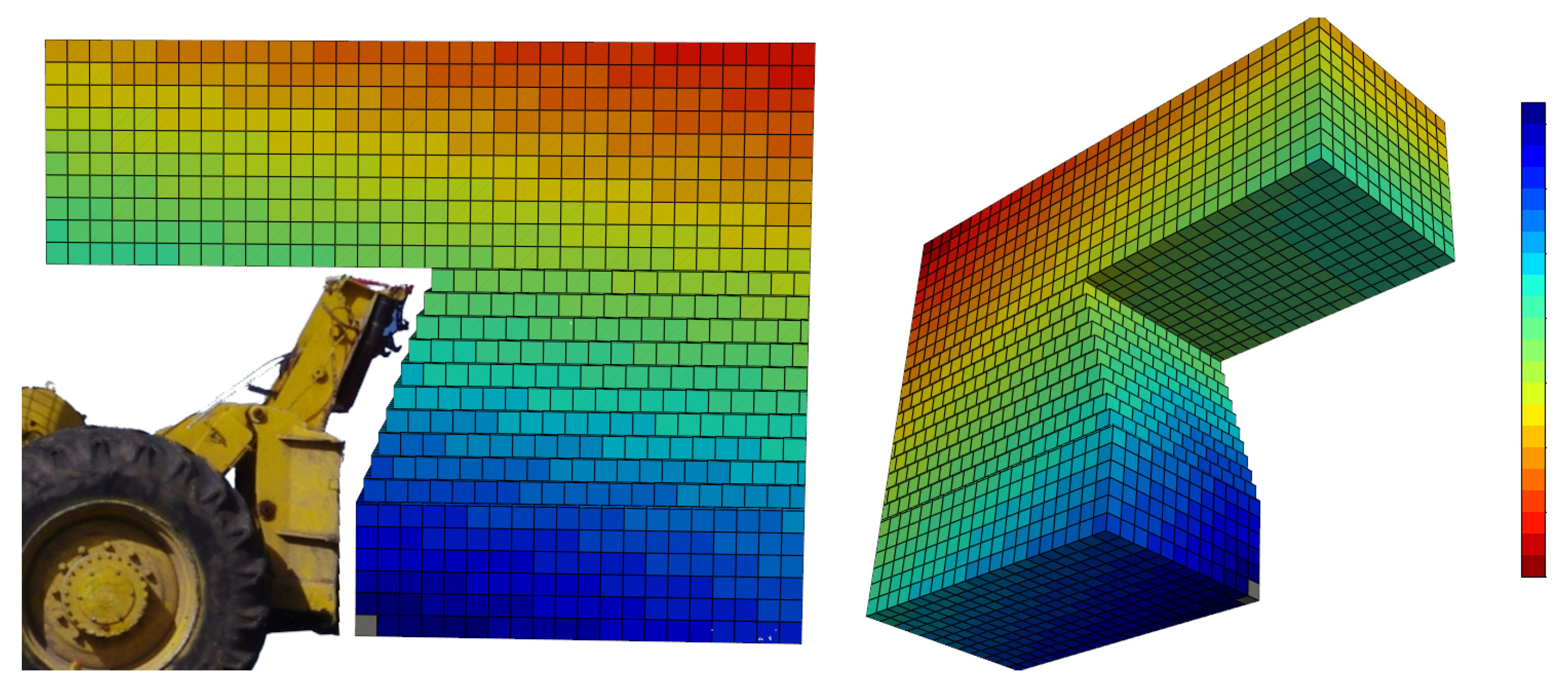
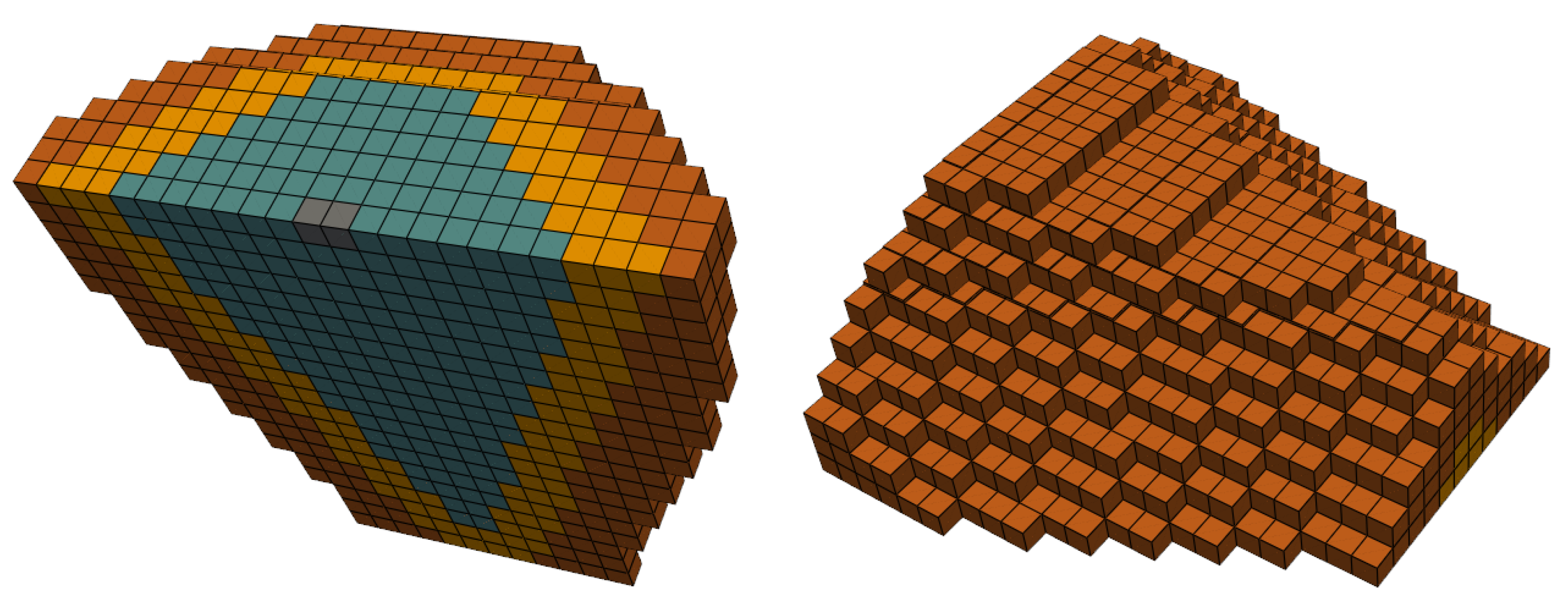
The shape of the tank is based on optimization, where all the available space, behind the rear shield, suitable for the tank is specified in the python code using prisms. The prisms copied the shape of the rear shield. The algorithm subsequently divided the prisms into a group of 1 L (or smaller) prisms of 10 cm × 10 cm × 10 cm size. Then, the influence of all the prisms of the group on vehicle stability was evaluated independently. The result of each evaluation was determined as the minimal value of distances of the gravity vector to the three sides of the stability triangle (as shown in Figure 3 and Figure 4), for maximal articulation of the skidder’s frame ( α = 45 ), excluding non-stable positions (white areas in Figure 4). When the whole group was processed, the results were reordered as shown in Table 2 and saved into a file. Then, an element in a higher row is more suitable to be used in the optimized shape of the tank from a stability point of view. These results can also be shown graphically (Figure 5). Thus, the figure shows the suitability of all the considered space, usable for a new tank shape, from the point of view of static stability. Then, a new tank can be created by reading the file row-by-row, and filtering the rows based on these criteria:
  • Overall volume of the tank, using elements’ volumes in the first column,
  • Position of the element, columns 2, 3 and 4.
This way we were able to create new tanks and analyze their static stability for all the ranges of the frame’s articulation and rotation of the skidder on a specified slope. An example of a result of such an analysis is shown in Figure 4. All the optimized tanks have a volume of 2000 L.

3. Results

To evaluate shape modifications of the tank, we created tanks that were wider, narrow, lower and higher, and allowed or banned the overhang part of the tank. All the shapes were compared with the basic manufactured water tank (Figure 1) with dimensions W × L × H = 1890 mm × 1073 mm × 1252 mm. Its stability is shown in Figure 6. The corner of all the tanks start in the point zero (see the gray point in all the following figures of the tanks) with coordinates [mm] X, Y, Z = [2385, 0, 300].
All the shapes of the tanks require different supporting structures. Their shapes and spatial distributions are unknown at this stage of research. We resolved this by increasing the weight of 1 L element of the tank from 1 kg (as corresponds to water) to 1.344 kg. We calculated this as 2000 L (=kg) times 1.344, which is equal to 2688 kg, which is the weight of the manufactured firefighting adapter (2000 L, Figure 1), which consisted from the water, the tank and the supporting structure.

3.1. Shape No. 1

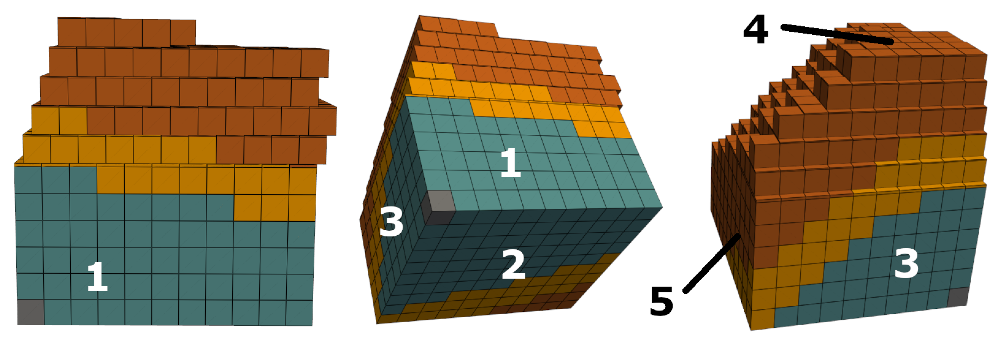
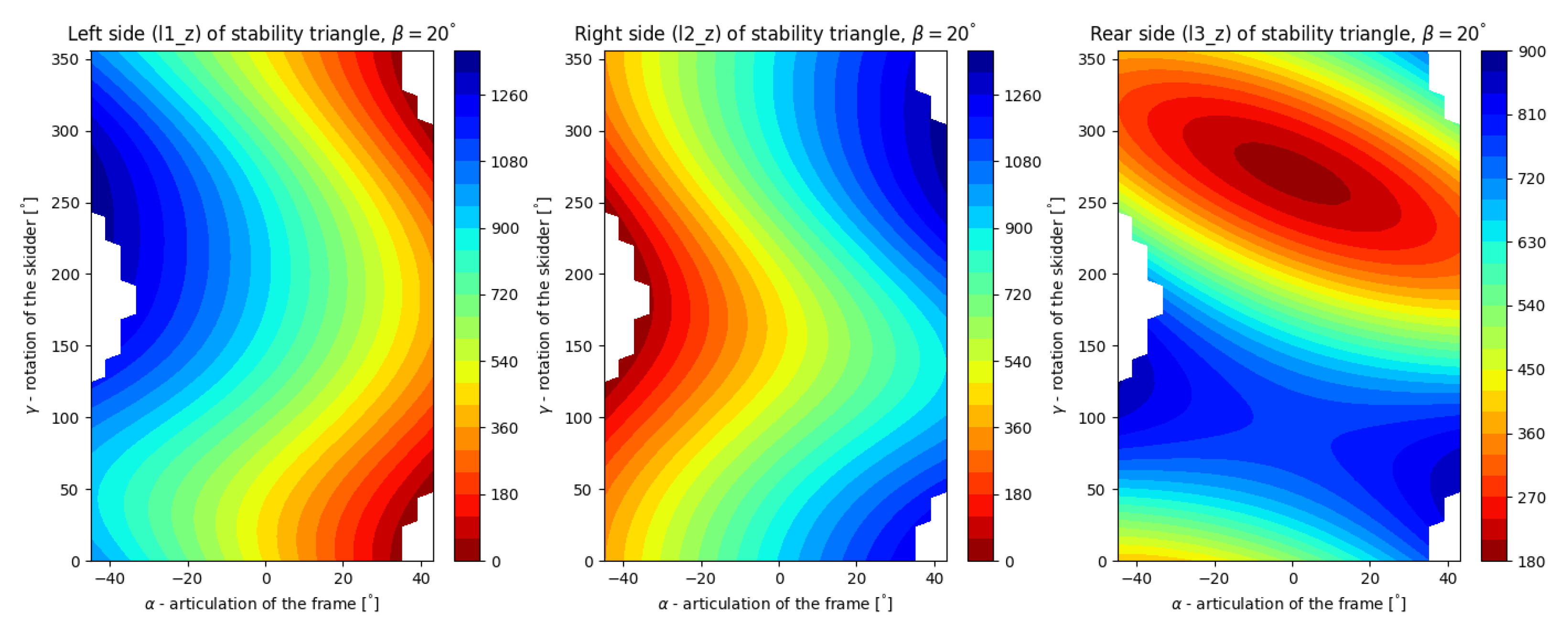
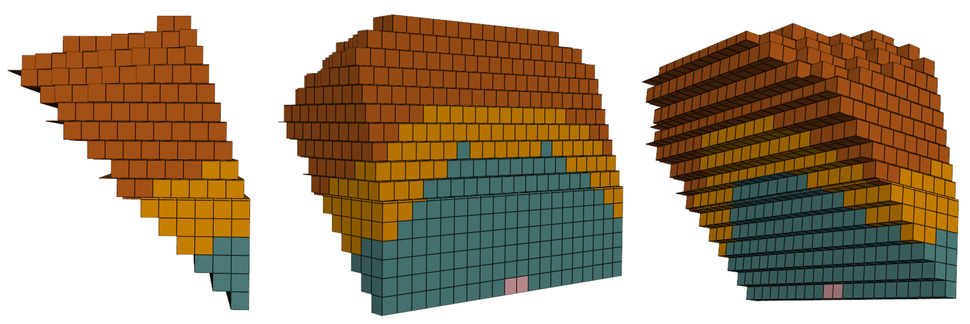
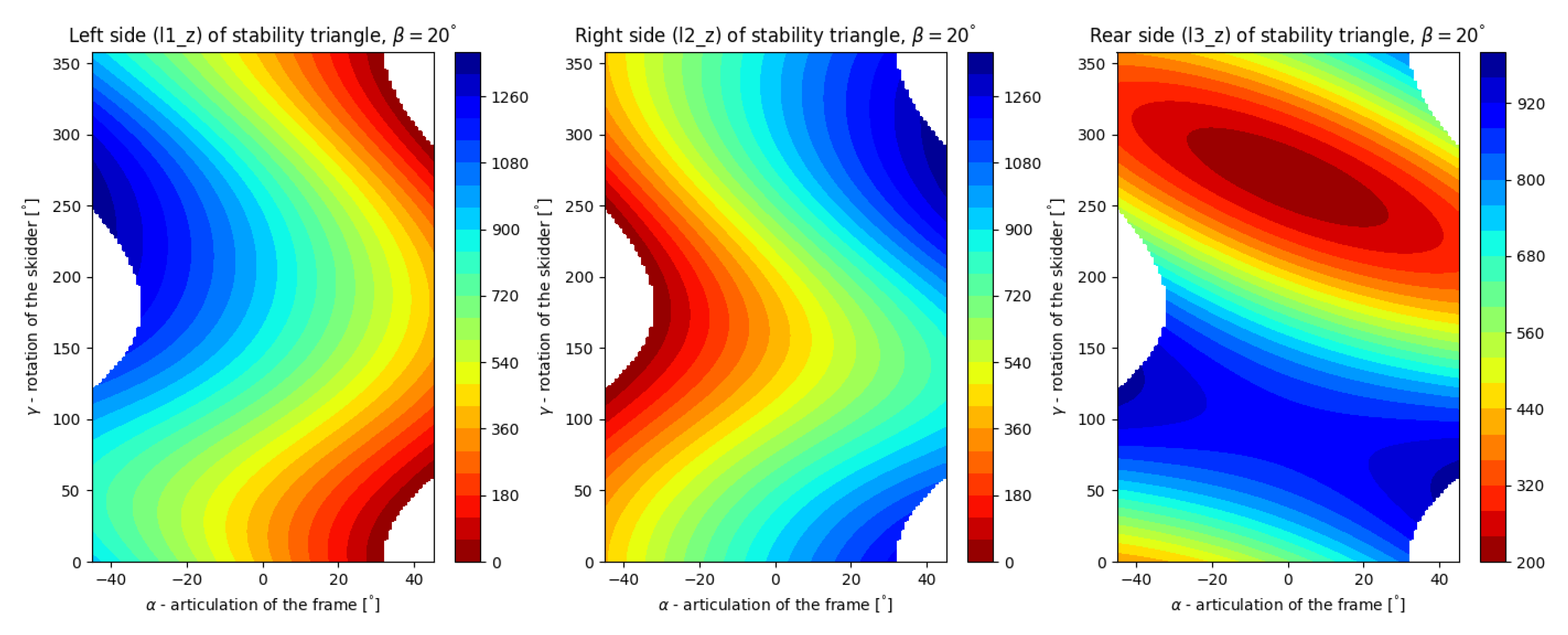
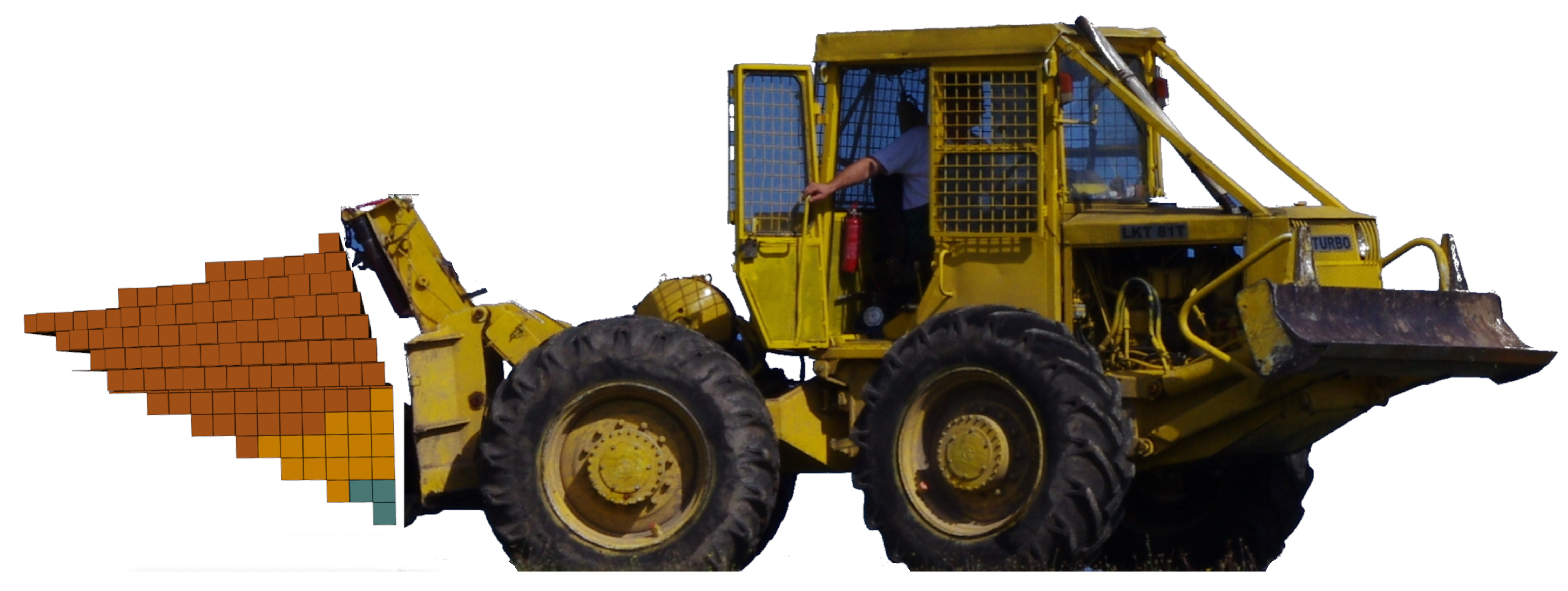
This shape (Figure 7) is similar to the fabricated tank, which means that it has a width of 1890 mm and a length of 1073 mm. The height of the tank is not limited (up to 2000 L). Stability of the tank, as shown in Figure 8, is the same as stability of the non-optimized tank, as shown in Figure 6.

3.2. Shape No. 2

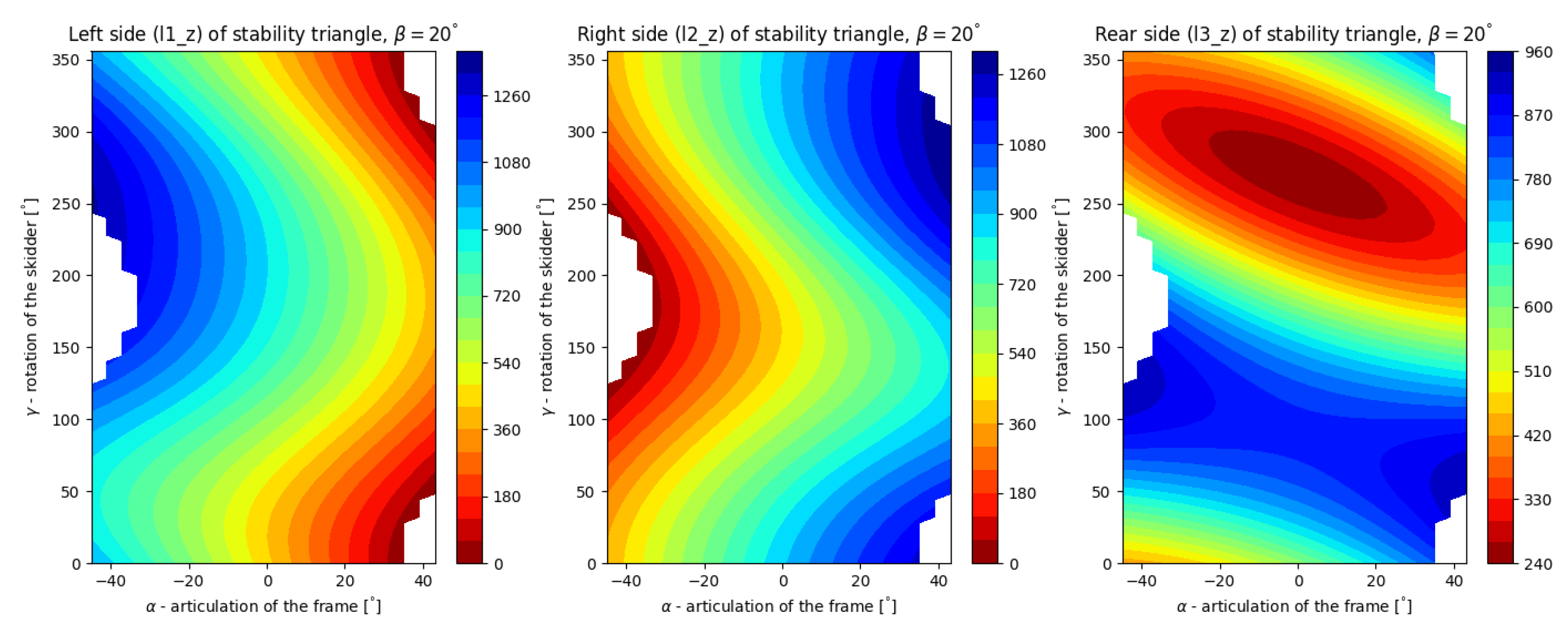
The shape (Figure 9) of this tank is limited by a width of 1890 mm only. This allows the tank to optimize its height and length. The result is the tank with a length of approximately 2000 mm and decreased height. As shown in Figure 10, its lateral stability is slightly better and its longitudinal stability is slightly worse.

3.3. Shape No. 3

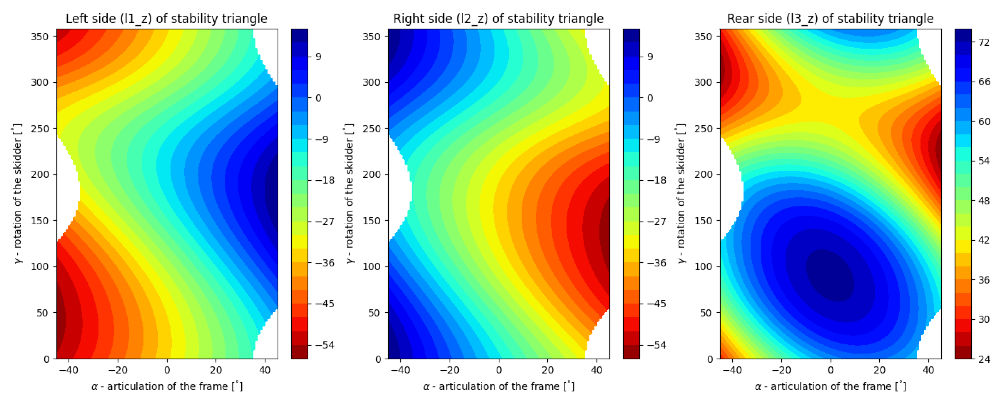
This shape is similar to the previous one, but the width is not limited either. The shape is then limited by overall optimized space as shown in Figure 5. The tank (Figure 11) has a maximal width of 2400 mm and a maximal length of 2000 mm. Its stability is visually the same as the stability of the previous tank. Figure 12 shows a comparison of stability values of the non-optimized tank minus the optimized tank in the shape of No. 3. The positive values on the color bars mean that the stability of the non-optimized tank is better. The comparison shows that the longitudinal stability of the non-optimized tank is better (third plot), and the lateral stability is mostly worse (first and second plot). That means that the lateral stability of the optimized tank is mostly better. Due to the large length of this and the previous shape, they are not suitable for difficult forest terrain.

3.4. Shape No. 4

The shapes mentioned above are not expressly better than the non-optimized tank in terms of stability. In this shape, we tried a sloping tank bottom, which can improve the machine’s terrain accessibility. As a first attempt, we designed a tank with a bottom slope of 45 , as shown in Figure 13, and width of 1890 mm. The longitudinal stability (Figure 14) of such a solution is slightly worse, the lateral stability is the same; however, the machine can lose lateral stability sooner if the angle of articulation ( α ) is higher.

3.5. Shape No. 5

This shape is derived from the previous shape, but it tries to utilize the overhanging part of the potential tank (as shown in Figure 5). Then, if suitable, elements can occupy that space, as shown in Figure 15. The lateral stability (Figure 16) of this solution is the same in comparison with shape No.4 and the longitudinal stability is better. The machine can lose lateral stability sooner, from the point of view of angle of the frame’s articulation. The construction of such a tank with supporting structure is complicated and probably not worth it in terms of stability.

3.6. Shape No. 6

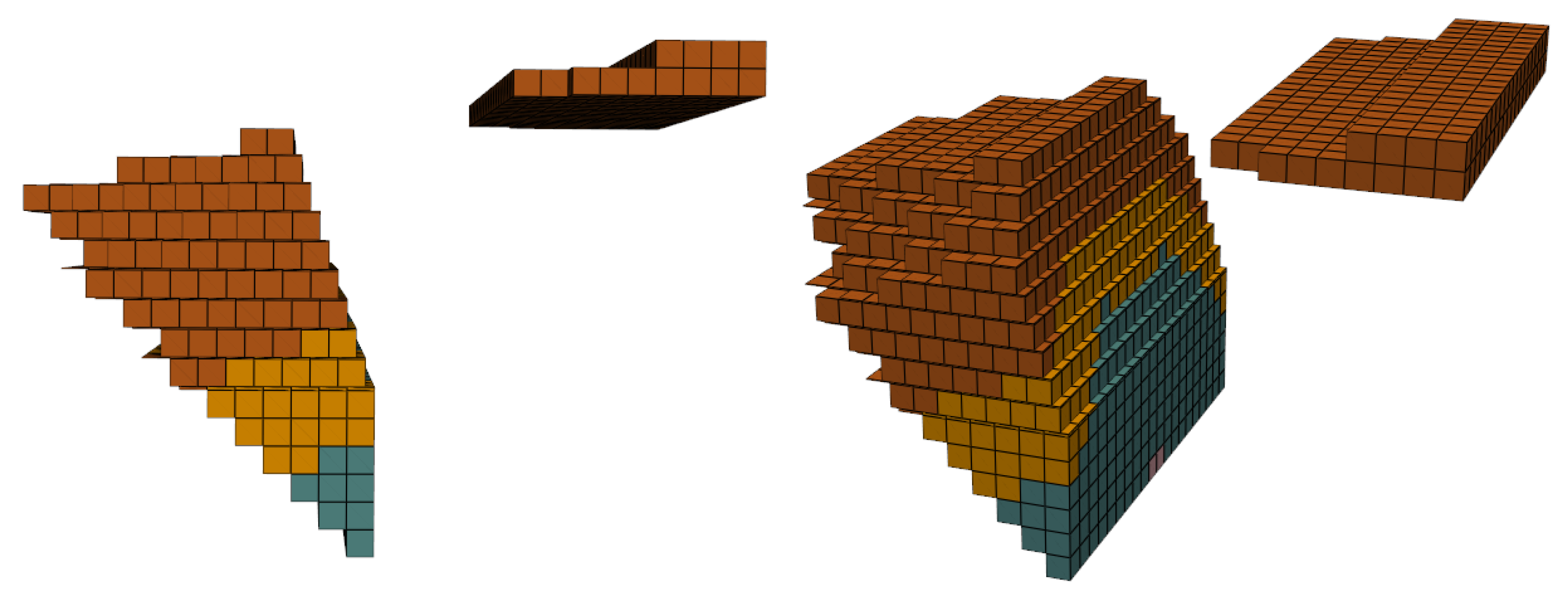
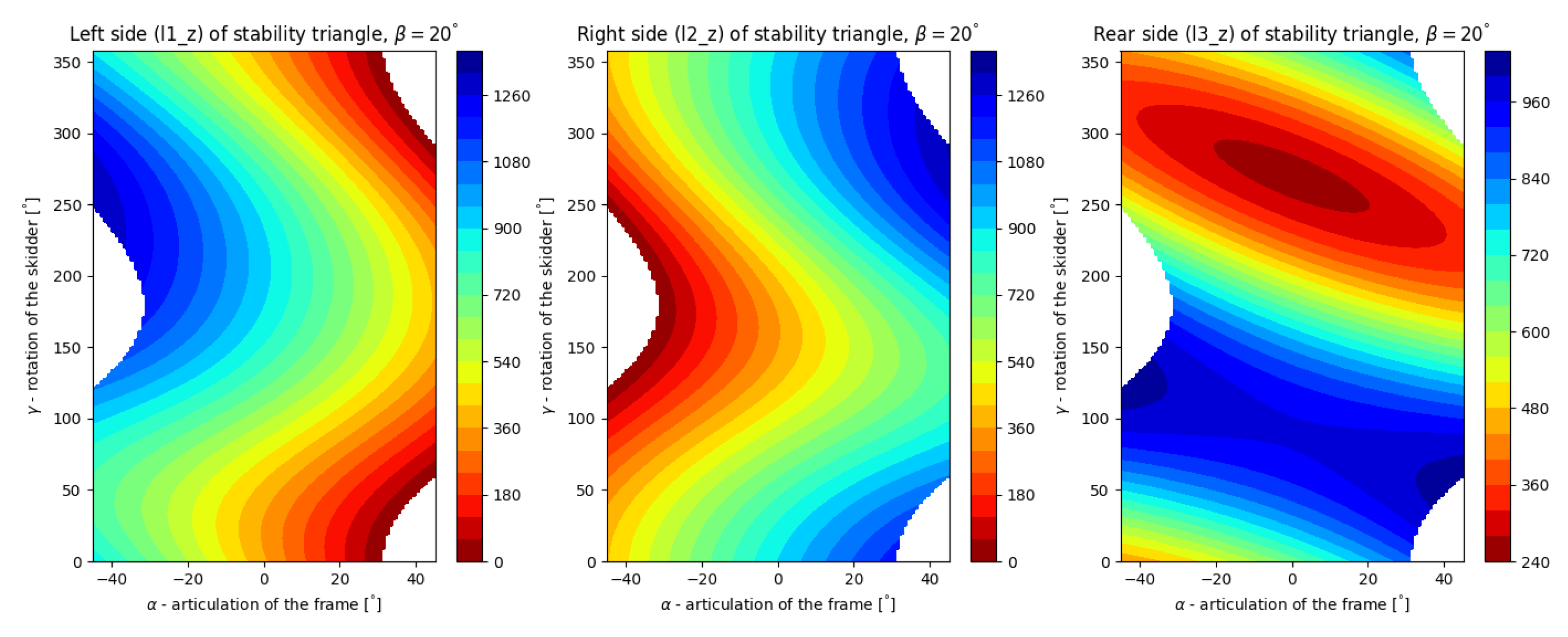
This shape (Figure 17) is a logical continuation of the shape No. 4. The tank does not contain elements in overhanging space and the bottom slope is 26 . 5 . This provides good terrain accessibility of the machine and enough space for growth of the tank up to required 2000 L. Stability of the tank (Figure 18), in comparison with shape No. 4, is better. The machine will lose its lateral stability later, and the longitudinal stability is also better.

3.7. Shape No. 7

This shape (Figure 19) continues in decreasing of bottom slope of the tank to 18 . 4 . The only limited parameter of the tank is the width, up to 1890 mm. The longitudinal stability (Figure 20) of the machine, in comparison with shape No. 6, is worse, while lateral stability is the same. The comparison with the non-optimized shape leads to the same conclusion.

3.8. Evaluation of Results

The tank shapes analyzed above cover nearly all possible variations, with the exception of those with a width of less than 1890 mm, which were not included in the study. A comparison of the results show that differences in stability are generally small, particularly in terms of lateral stability. Differences in longitudinal stability are slightly more noticeable, but still relatively small. In cases where the machine loses stability, it is primarily due to insufficient lateral stability. Shapes No. 2 and No. 3 offer the best lateral stability, but perform the worst in terms of longitudinal stability. This outcome is expected, as the shapes shift the center of gravity downward and further away relative to the rear axle. The analysis indicates that the tank’s shape is neither the only nor the primary factor influencing stability. Key parameters also include the tank’s weight or volume and its position. The shapes alone do not lead to significantly improved stability. Therefore, the main conclusion is that shape optimization may contribute more significantly to improving the machine’s terrain accessibility than to enhancing its stability. Considering this conclusion, shape No. 6 appears to be the most suitable (Figure 21). While it provides slightly lower lateral and longitudinal stability compared to the non-optimized shape, it offers a major advantage in terms of improved terrain accessibility of the vehicle. In practical terms, this shape can serve as a baseline design for creating a new water tank tailored to a currently produced skidder. From a structural perspective, the preferred design concentrates the mass as close as possible to the skidder, where the supporting structure connects the tank to the machine’s frame, with what is appropriate in terms of tension in the structure.

4. Discussion

The primary objective of this research was to optimize the shape of a water tank integrated into a firefighting adapter. The sole criterion for optimization was static stability, taking into account the articulated frame of the skidder, which features an oscillating front axle. Numerous tank shapes were designed and analyzed, with seven selected for inclusion in the study based on the results they provided. The findings demonstrated that while tank shape does affect stability, the differences were relatively minor. Among the tested configurations, shape No. 6 emerged as the most favorable. Although it exhibited slightly lower lateral and longitudinal stability, it significantly improved terrain accessibility of the vehicle. As illustrated in Figure 3, when the center of gravity (T) shifts toward the rear axle, due to weight positioned behind the vehicle, lateral stability increases, while longitudinal stability decreases. This is reflected in higher values of l 1 _ z and l 2 _ z , and a lower value of l 3 _ z . From a firefighting perspective, larger tanks are generally preferable. Compared to the non-optimized design (see Figure 1), the final version of shape No. 6 is far more suitable for navigating rugged forest terrain. In terms of static stability, a sloped tank bottom does not negatively affect performance and contributes to improved terrain accessibility. It is important to note that the stability assessed in this study, defined by the distances between the gravity vector and the tipping lines ( l 1 _ z , l 2 _ z , and l 3 _ z in Figure 3), is purely static. Adding weight, such as a water tank, to the front of the vehicle may enhance stability, but it also increases total mass of the vehicle, making the machine more susceptible to terrain irregularities. However, these effects pertain to dynamic stability, which was beyond the scope of this research. All analyzed tanks were at least 1890 mm wide. While this could be seen as a methodological limitation, all tank designs were symmetrical. From a logical perspective, mass distributed in the XZ plane exerts minimal negative impact on the vehicle’s stability. Therefore, it can be concluded that a larger width generally increases stability because it can concentrate the mass in the desired position. However, a wider tank may place greater demands on the design of the mounting mechanism, making overly wide or narrow tanks less practical. The proposed solution appears to be unique in both the tank’s placement and its shape. These findings can inform future research and development of a new water tank for commercially available skidders.

5. Conclusions

This study aimed to optimize the shape of a 2000 L water tank mounted on a forestry skidder, with the primary goal of enhancing the vehicle’s static stability on sloped terrain. Using a vector-based mathematical model and simulation tools implemented in Python, multiple tank geometries were analyzed for their effects on the vehicle’s center of gravity and corresponding distances to the sides of the stability triangle. The results showed that while tank shape does influence stability, the differences were generally minor. In many cases, improving lateral stability came at the cost of reduced longitudinal stability and vice versa. Among the seven designs evaluated, shape No. 6 stood out as the most balanced option. Although it showed slightly lower lateral and longitudinal stability compared to the original tank, it significantly improved the vehicle’s terrain accessibility due to its sloped bottom design. The modeling and evaluation method developed in this work proved to be both flexible and scalable. It can be adapted to various vehicle types, tank configurations or additional mounted equipment. This makes it a valuable tool for broader engineering applications beyond the specific use case studied here. Future research should explore dynamic stability effects and the detailed design of the tank’s mounting and supporting structures. In the first phase they can copy the initial design and add a support mechanism, e.g., a folding one, to stabilize the tank at rest to compensate for the tilted tank bottom. Additional practical concerns, such as tank fabrication, refill logistics and integration with skidder systems, will also need to be addressed for field implementation.
In summary, this study offers a solid foundation for designing firefighting adapters that are both more stable and better suited for rugged terrain. Shape No. 6 represents an effective compromise between static stability and operational performance, making it a strong candidate for future development.

Author Contributions

Conceptualization and methodology, J.M.; validation, J.M., and M.H.; formal analysis and investigation, J.M. and M.H.; resources, J.M. and M.H.; data curation, J.M.; writing—original draft preparation, J.M.; software, J.M.; writing—review, editing and visualization, J.M.; supervision, J.M. All authors have read and agreed to the published version of the manuscript.

Funding

This research was funded by “Operational Programme Integrated Infrastructure” (contract ITMS 313011T720). This article is the result of the project VEGA Nr. 1/0121/24 Prediction of the remaining useful life of energy carriers in the operation of circulation systems of technical equipment for woodworking and processing using statistical degradation models.

Data Availability Statement

The original contributions presented in this study are included in the article. Further inquiries can be directed to the corresponding author.

Conflicts of Interest

The authors declare no conflict of interest.

References

  1. Forest Research. Forest Fires and Climate Change. Available online: https://www.forestresearch.gov.uk/research/climate-change-impacts/forest-fires-and-climate-change/ (accessed on 24 June 2022).
  2. Wiesik, J.; Aniszewska, M. Urzadzenia Techniczne w Produkcji Lesnej; SGGW: Warszawa, Poland, 2011; pp. 237–240. [Google Scholar]
  3. Fire Apparatus Magazine. Wildland Firefighting 4 × 4 Brush Truck. Available online: https://www.fireapparatusmagazine.com/fire-apparatus/wildland-firefighting-4x4-brush-truck/ (accessed on 11 July 2022).
  4. Howe and Howe. Termite. Available online: https://www.howeandhowe.com/civil/thermite (accessed on 11 July 2022).
  5. BAI. Fire Fighting and Rescue Vehicles. Available online: https://www.bai.it/en/ (accessed on 11 July 2022).
  6. Jarvis, R. An autonomous heavy duty outdoor robotic tracked vehicle. In Proceedings of the 1997 IEEE/RSJ International Conference on Intelligent Robot and Systems. Innovative Robotics for Real-World Applications. IROS ’97, Grenoble, France, 11 September 1997; Volume 1, pp. 352–359. [Google Scholar] [CrossRef]
  7. Cao, S.; Chen, S.; Yu, W.; Chen, S.; Xu, X. Research on Ride Comfort of Diminutive Forest Fire-fighting Vehicles. Open Autom. Control Syst. J. 2014, 6, 706–710. [Google Scholar] [CrossRef]
  8. Hnilica, R.; Ťavodová, M.; Hnilicová, M.; Matej, J.; Messingerová, V. The Innovative Design of the Fire-Fighting Adapter for Forest Machinery. Forests 2020, 11, 843. [Google Scholar] [CrossRef]
  9. Matej, J.; Hnilica, R.; Hnilicová, M. Research on Static Stability of Firefighting Adapter. Forests 2022, 13, 1180. [Google Scholar] [CrossRef]
  10. Gibson, H.G.; Elliott, K.C.; Persson, S.P.E. Side Slope Stability of Articulated-Frame Logging Tractors. J. Terramech. 1971, 8, 65–79. [Google Scholar] [CrossRef]
  11. Franceschetti, B.; Rondelli, V.; Capacci, E. Lateral Stability Performance of Articulated Narrow-Track Tractors. Agronomy 2021, 11, 2512. [Google Scholar] [CrossRef]
  12. Sierzputowski, G.; Dudziński, P. A mathematical model for determining and improving rollover stability of four-wheel earthmoving vehicles with arbitrary undercarriage system design. Arch. Civ. Mech. Eng. 2020, 20, 52. [Google Scholar] [CrossRef]
  13. Bołoz, Ł.; Kozłowski, A. Methodology for Assessing the Stability of Drilling Rigs Based on Analytical Tests. Energies 2021, 14, 8588. [Google Scholar] [CrossRef]
  14. Tomašić, Ž.; Šušnjar, M.; Horvat, D.; Pandur, Z. Forces Affecting Timber Skidding. Croat. J. For. Eng. 2009, 30, 2. [Google Scholar]
  15. Bietresato, M.; Mazzetto, F. Increasing The Safety of Agricultural Machinery Operating on Sloping Grounds by Performing Static and Dynamic Tests of Stability on a New-Concept Facility. Int. J. Saf. Secur. Eng. 2018, 8, 77–89. [Google Scholar] [CrossRef]
  16. Bietresato, M.; Mazzetto, F. Definition of the Layout for a New Facility to Test the Static and Dynamic Stability of Agricultural Vehicles Operating on Sloping Grounds. Appl. Sci. 2019, 9, 4135. [Google Scholar] [CrossRef]
  17. Bietresato, M.; Mazzetto, F. Stability Tests of Agricultural and Operating Machines by Means of an Installation Composed by a Rotating Platform (the “Turntable”) with Four Weighting Quadrants. Appl. Sci. 2020, 10, 3786. [Google Scholar] [CrossRef]
  18. Majdan, R.; Abrahám, R.; Tkáč, Z.; Drlička, R.; Matejková, E.; Kollárová, K.; Mareček, J. Static Lateral Stability of Tractor with Rear Wheel Ballast Weights: Comparison of ISO 16231-2 (2015) with Experimental Data Regarding Tyre Deformation. Appl. Sci. 2021, 11, 381. [Google Scholar] [CrossRef]
  19. ISO 16231-2:2015; Self-Propelled Agricultural Machinery-Assessment of Stability Part 2: Determination of Static Stability and Test Procedures. International Organization for Standardization: Geneva, Switzerland, 2015. Available online: https://www.iso.org/standard/61583.html (accessed on 11 July 2025).
  20. Mazzetto, F.; Bietresato, M.; Gasparetto, A.; Vidoni, R. Simulated stability tests of a small articulated tractor designed for extreme-sloped vineyards. J. Agric. Eng. 2013, XLIV (Suppl. S1), e133. [Google Scholar] [CrossRef]
  21. Demšar, I.; Bernik, R.; Duhovnik, J. A Mathematical Model and Numerical Simulation of the Static Stability of a Tractor. Agric. Conspec. Sci. 2012, 77, 143–150. [Google Scholar]
  22. Bołoz, Ł.; Kozłowski, A.; Horak, W. Assessment of the stability of BEV LHD loader. Manag. Syst. Prod. Eng. 2022, 30, 377–387. [Google Scholar] [CrossRef]
  23. Tianlong, L.; Jixin, W.; Zongwei, Y. Modelling and Stability Analysis of Articulated Vehicles. Appl. Sci. 2021, 11, 3663. [Google Scholar] [CrossRef]
  24. Tota, A.; Galvagno, E.; Velardocchia, M. Analytical Study on the Cornering Behavior of an Articulated Tracked Vehicle. Machines 2021, 9, 38. [Google Scholar] [CrossRef]
  25. Reński, A. Investigation of the Influence of the Centre of Gravity Position on the Course of Vehicle Rollover. In Proceedings of the 24th Enhanced Safety of Vehicles Conference, Gothenburg, Sweden, 8–11 June 2015; Available online: https://www.researchgate.net/publication/279449206_Investigation_of_the_Influence_of_the_Centre_of_Gravity_Position_on_the_Course_of_Vehicle_Rollover (accessed on 24 June 2022).
  26. Keisan Online Calculator: Shortest Distance Between Two Lines Calculator. Available online: https://web.archive.org/web/20220802094641/https://keisan.casio.com/exec/system/1223531414 (accessed on 16 November 2021).
  27. Duka, A.; Poršinsky, T.; Pentek, T.; Pandur, Z.; Vusić, D.; Papa, I. Mobility Range of a Cable Skidder for Timber Extraction on Sloped Terrain. Forests 2018, 9, 526. [Google Scholar] [CrossRef]
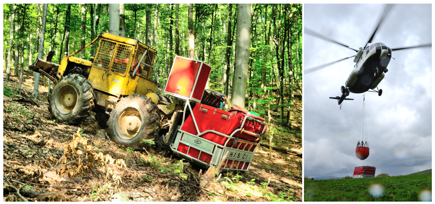
Figure 1. Firefighting adapter attached to forestry skidder. Filling water tank with Bambi bucket.
Asi 08 00112 g001
Figure 2. Important points of skidder: FRW, FLW, RLW, RRW—coordinates of contact points of tires with slope/terrain, FG, RG—coordinates of centers of gravities for front and rear frames of skidder, RAW—coordinates of rear mount points for additional weight/load, FFCS—front frame coordinate system (with Z-axis toward up), RFCS—rear frame coordinate system (with Z-axis toward up), FPP—coordinates of front axle pivot point. Adopted from [9].
Asi 08 00112 g002
Figure 3. (A) Scheme of position of skidder with oscillating front axle on slope: α—articulation of frame [], β—slope angle [], γ—rotation (=position) of skidder on slope [], l 1 _ z , l 2 _ z , l 3 _ z —sides of stability triangle (left, right and rear one). RLW, RRW—coordinates of contact points of rear tires with slope/terrain, T—center of gravity of skidder. Three green lines show distances of gravity vector (through T, center of gravity) to sides of stability triangle (=tipping lines) in 3D space. (B) 3D view of another skidder position on slope with β gradient. Adopted from [9].
Asi 08 00112 g003
Figure 4. Visualization of stability with input variables α (articulation of frame), γ (rotation of skidder) and constant value β (slope angle). P—a combination of input parameters, A—area of instability, left tipping line (left side of stability triangle), B—area of instability, right tipping line, C—area of instability, rear tipping line. D—lateral stability (left tipping line), E—lateral stability (right tipping line), F—longitudinal stability (rear tipping line). Color bars show distance of gravity vector (for whole machine, including additional loads) to tipping lines in [mm]. Adopted [9].
Asi 08 00112 g004
Figure 5. Suitability of 1 L elements of new potential shape of tank, in terms of stability. Blue color—the highest suitability, red color—the lowest suitability. Only right half of potential tank is displayed.
Asi 08 00112 g005
Figure 6. Stability of non-optimized 2000 L tank.
Asi 08 00112 g006
Figure 7. Optimized tank—shape No. 1. 1—XZ plane, 2—bottom side of tank, 3—front side, 4—top side, 5—right side. Colors (for all the figures) correspond to volumes: blue—the first 500 L, orange—plus another 500 L, brown—plus another 1000 L. Only right half of tank is displayed.
Asi 08 00112 g007
Figure 8. Stability of optimized tank—shape No. 1.
Asi 08 00112 g008
Figure 9. Optimized tank—shape No. 2. Only right half of tank is displayed.
Asi 08 00112 g009
Figure 10. Stability of optimized tank—shape No. 2.
Asi 08 00112 g010
Figure 11. Optimized tank—shape No. 3.
Asi 08 00112 g011
Figure 12. Comparison of stability for optimized tank—shape No. 3. Plot shows stability of non-optimized tank minus stability of tank in shape No. 3.
Asi 08 00112 g012
Figure 13. Optimized tank—shape No. 4.
Asi 08 00112 g013
Figure 14. Stability of optimized tank—shape No. 4.
Asi 08 00112 g014
Figure 15. Optimized tank—shape No. 5.
Asi 08 00112 g015
Figure 16. Stability of optimized tank—shape No. 5.
Asi 08 00112 g016
Figure 17. Optimized tank—shape No. 6.
Asi 08 00112 g017
Figure 18. Stability of optimized tank—shape No. 6.
Asi 08 00112 g018
Figure 19. Optimized tank—shape No. 7.
Asi 08 00112 g019
Figure 20. Stability of optimized tank—shape No. 7.
Asi 08 00112 g020
Figure 21. Illustration of the new, optimized tank, shape No. 6, with base skidder.
Asi 08 00112 g021
Table 1. Basic parameters of alternative skidder model (as shown in Figure 2) [9].
Coordinates of important points (x, y, z) [mm]FPP (−1200, 0, 500), RRW (1200, 1010, 0), RLW (1200, −1010, 0), FRW (−1200, 1010, 0), FLW (−1200, −1010, 0), FG (−1100, 0, 1000), RG (1100, 0, 800)
Gravities [N]FG (gravity) = 0.615 × 7145 kg × 9.81 m/s2 = 43,106 N, RG (gravity) = 0.385 × 7145 kg × 9.81 m/s2 = 26,985 N (skidder’s weight of 7145 kg, where 61.5% is on front axle)
Table 2. Reordered results of influence of 1 L (or smaller) elements of water tank on stability. Each line contains volume of element [L], its position (corner.x/y/z) [mm], its size [mm], and result (as suitability [mm]).
VolumeCorner.xCorner.yCorner.zSize.xSize.ySize.zSuitability
1.02385030010010010057.371803
1.0238510030010010010057.335552
1.02385040010010010057.34385
1.02485040010010010057.33817
Disclaimer/Publisher’s Note: The statements, opinions and data contained in all publications are solely those of the individual author(s) and contributor(s) and not of MDPI and/or the editor(s). MDPI and/or the editor(s) disclaim responsibility for any injury to people or property resulting from any ideas, methods, instructions or products referred to in the content.