1. Introduction
Using wind turbines in small-scale and urban environments is becoming increasingly relevant. Various turbine configurations, both vertical and horizontal axes, have been well investigated and summarized by many authors [
1,
2,
3]. Vertical-axis wind turbines (VAWTs) were initially considered very promising before being superseded by modern horizontal-axis turbines. For various reasons, there is currently a rising tide of interest in VAWTs, in particular, in Darrieus turbines. Using modern design tools and computational approaches, the performance of traditional VAWTs can be significantly improved, reaching a level almost comparable to horizontal-axis turbines. Since VAWTs have many specific advantages (compact design, easier connection to gearboxes/generator, easier blade control, if necessary, maintainability), it is important to quantify the efficiency of such turbines.
Of particular interest are small vertical-axis wind turbines, which are considered effective for micro-power generation [
4]. In moderate wind conditions, such turbines are widely used as a reliable source of electricity [
5]. To improve the efficiency of wind turbines, the design of blades with an airfoil profile that provides a good thickness ratio and aerodynamic characteristics plays a key role [
6]. A properly selected blade profile helps to increase the lift coefficient of the turbine. To achieve the maximum torque and power factor, the blades must provide high lift with minimum drag. Thus, the correct selection of blade design is critical to improving the efficiency of vertical-axis wind turbines [
4].
In recent years, various asymmetric blades have been found to have greater potential than the symmetric NACA (National Advisory Committee for Aeronautics) airfoils for three-bladed Darrieus rotors. To select the optimal blade profile, an analysis of existing studies was conducted to identify the characteristics of the proposed designs. Beri and Yao studied the effect of a modified NACA 0018 airfoil in the trailing edge region on the self-starting ability at a low tip speed ratio (TSR) using 2D computational fluid dynamics (CFD) analysis and compared the simulation results with NACA 2415, which has self-starting ability. They found that the modified airfoil showed better self-starting results under both transient and steady flow conditions for their turbine model [
7]. Subsequently, Beri and Yao performed a 2D CFD analysis under unsteady conditions for a three-bladed Darrieus rotor with NACA 2415 asymmetric blades. The rotor exhibited average torque, sufficient for the self-starting of the blades [
8].
Gupta and Biswas investigated the aerodynamic and energy characteristics of a three-bladed Darrieus rotor based on a NACA 0012 swirling airfoil. The simulations were carried out under steady-state conditions using 2D CFD analysis and the standard k-ε turbulence model [
9]. Deshpande and Li analyzed a three-bladed H-Darrieus rotor using two symmetric airfoils, i.e., NACA0018 and NACA0015, and an asymmetric airfoil, i.e., S1210, and noted several advantages of the asymmetric S1210 blades for a fixed-pitch rotor [
10]. Bhuyan and Biswas conducted an experimental study on a Darrieus rotor with three asymmetric S818 blades featuring increased thickness and a high blade solidity ratio to assess its self-starting capability [
11]. Singh et al. experimentally investigated a three-bladed Darrieus rotor with asymmetric S1210 blades to evaluate its power coefficient and self-starting capability at various blade-to-diameter ratios and low wind speeds. However, these studies did not pay enough attention to the blade–flow interaction at different azimuthal positions of Darrieus rotors at low wind velocities [
12].
Danao et al. used CFD analysis to investigate the effect of blade curvature and thickness on the performance of a Darrieus rotor using two asymmetric airfoils, NACA 5522 and LS0421. They came to the conclusion that a slightly curved and thick airfoil could improve the overall performance of the Darrieus rotor. Their study examined the interaction between the flow and the blades of Darrieus rotors with a high blade solidity ratio, featuring both asymmetric and symmetric blades, to evaluate their performance under low wind speed conditions using detailed CFD simulations [
13]. The S815 airfoil was chosen for the study because it has a higher thickness and lower curvature percentage compared to other popular NREL S-series airfoils such as S1210, S809, and S818. The NACA 0018 airfoil, which is widely used for Darrieus rotors and has a higher power factor compared to other NACA series airfoils, was chosen as a comparison. In [
14], the aerodynamic characteristics of the rotor were investigated in the form of blade interaction with the flow at different azimuthal angles, pressure coefficients, and changes in the lift-to-drag ratio. The effect of changes in low wind speeds on the blade interaction with the flow at different azimuthal positions of the rotor was also assessed.
Mazarbhuiya et al. [
15] investigated the effect of positive and negative tilt angles on asymmetric blades.
Shouman et al. [
16] used the curtain arrangement and rib addition on blades to improve the performance of Savonius rotors. They conducted CFD simulations to study the impact of the curtain arrangement and rib addition on the rotor performance. They were able to improve the performance by about 42% versus a conventional rotor.
The authors of study [
17] analyzed key factors of aerodynamic design, as well as their advantages and disadvantages, and proposed a baseline VAWT design for further analysis. Particular attention was given to the potential applications of VAWTs for both large-scale offshore wind energy and small urban installations. However, the issue of aerodynamic optimization was not fully addressed.
Further development of the proposed designs involves modifying the blade geometry. One such solution is the use of J-shaped blades, which enhance self-starting capability and exhibit unique aerodynamic characteristics. Other approaches include variable blade pitch angles [
18,
19] and hybrid configurations that combine Darrieus and Savonius VAWTs [
20,
21]. The high static torque generated by the Savonius turbine at a low TSR can be utilized to facilitate the self-starting of the Darrieus turbine.
In addition to hybrid solutions aimed at improving the self-starting ability of VAWTs, other methods of blade geometry modification have also been explored. In [
22], a 3D numerical analysis of J-type blades in VAWTs was performed. It was found that they form stronger vortices, reducing the torque at high TSRs, but they improve self-starting. Replacing straight blades with J-shaped ones increases the torque by 26.9% at 10 m/s and by 37.6% at 5 m/s, which makes them promising for low-speed wind in cities. Continuing the research on improving the aerodynamic characteristics of vertical-axis wind turbines, a new three-piece blade VAWT (3-PB VAWT) was proposed, combining the advantages of straight-bladed and screw turbines. Numerical modeling showed that this design provides more stable torque. In particular, the 3-PB VAWT increases the torque coefficient by 6.06% at a low TSR (0.44) and by 158.19% at a high TSR (1.77), combining high aerodynamic efficiency with low production cost [
23]. In addition to blade shape optimization, an important area of research has been improving the starting performance of VAWTs. In this context, various methods have been proposed to address the low starting torque issue and improve the overall turbine efficiency. In addition, further research has shown that not only the starting performance but also the overall performance of VAWTs can be improved by changing the blade shape. In particular, using helical blades instead of straight blades has improved the turbine efficiency at high tip speed ratios (TSRs). The optimal twist angle for a tested turbine was found to be 60 degrees, as it provides the best aerodynamic performance [
24]. In addition to the shape and twist angle of the blades, the number of rotor blades also has a significant impact on the aerodynamic efficiency of a turbine. Another geometric parameter that has a significant impact on turbine performance is the number of rotor blades. In a computational investigation of an H-shaped Darrieus wind turbine, it was shown that a turbine with a higher number of blades performs better at low TSR values. However, as the TSR increased, a turbine with fewer blades achieved a higher power factor [
25].
Another study found that a three-bladed turbine produced the highest torque, while a four-bladed turbine produced the least destructive vibrations in the gearbox [
26]. The aspect ratio, which is the ratio between the radius and height of the rotor, has a significant effect on the turbine efficiency. The results of another study showed that as the aspect ratio decreases, the Reynolds number increases, which in turn leads to an increase in VAWT efficiency [
27].
The blade pitch angle, which determines the position of the blade’s leading edge and directly affects the attack angle, is considered to be an important design parameter. Based on the results of a previous study, the best performance was achieved with a negative blade pitch angle, and as it increased, the Cp power factor values decreased [
28].
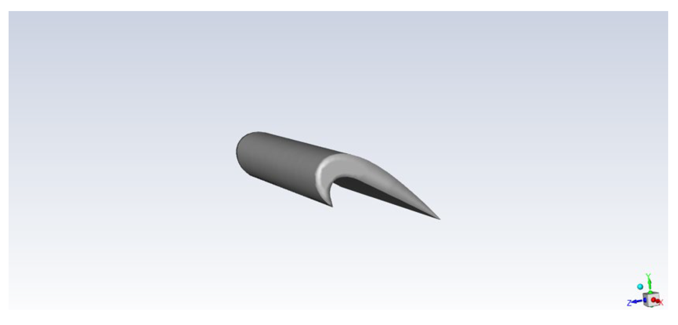
Based on the analysis of the above studies, to address the issue of the self-starting and efficiency of the Darrieus turbine, we have proposed an original asymmetric blade profile design [
29]. The NACA0021 profile was chosen as a basis, and a part of the same blade of a smaller scale was cut out from it.
Figure 1 shows our blade with the distribution of aerodynamic forces acting on the blade.
The presented profile is optimized for operation at different rotation-speed-to-wind-velocity (TSR) ratios, which makes it universal for a wide range of wind conditions. The wind turbine blade has an aerodynamic profile with a rounded nose and an extended trailing edge, which increases lift and reduces drag. The upper surface is convex, enhancing the flow, and the lower one reduces induced drag. Smooth transitions of the profile coordinates minimize swirls and turbulence.
Thus, the developed blade profile combines optimized aerodynamic characteristics that can contribute to increasing the efficiency of the Darrieus rotor. However, despite the confirmed theoretical advantages, experimental and numerical studies are needed to evaluate the impact of asymmetric blades on the operation of wind turbines.
This paper examines the aerodynamic characteristics of a Darrieus rotor with the proposed asymmetric blades in two design configurations—with and without horizontal parallel plates. To obtain reliable data, experimental studies were conducted in a wind tunnel, as well as numerical CFD modeling in ANSYS Fluent.
2. Experimental Study of Rotor Design
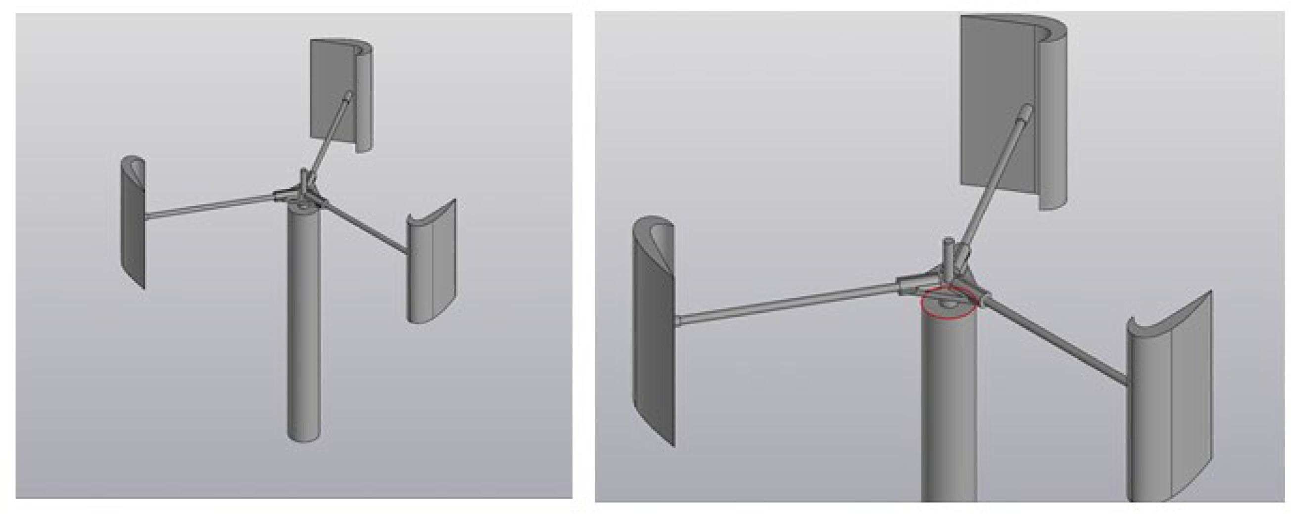
The experimental study was performed using two different rotor designs, as shown in
Figure 2.
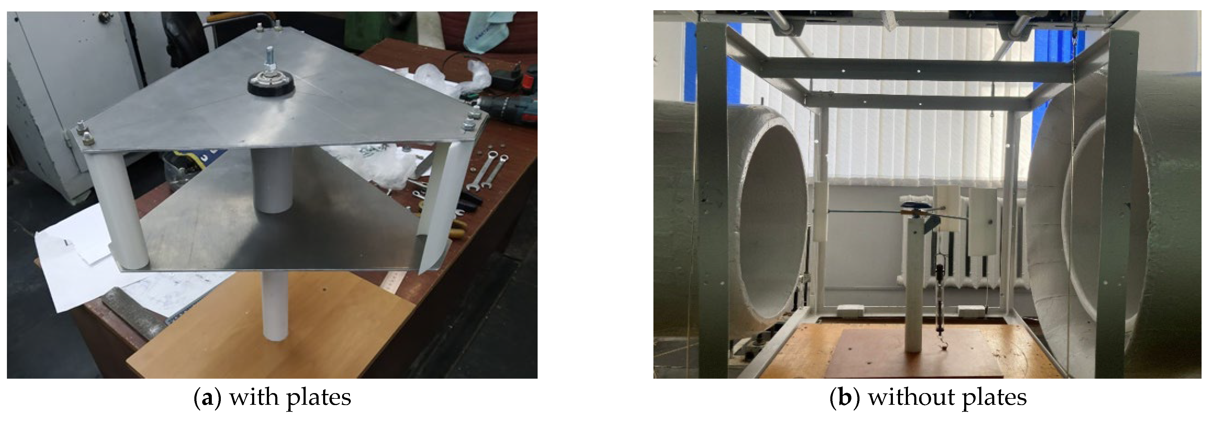
The first design (
Figure 2a) is a Darrieus rotor with three asymmetrical blades secured between two horizontal parallel metal plates. The second design (
Figure 2b) is a similar rotor, but with no horizontal plates, making it possible to compare the impact of the plates on the aerodynamic characteristics of the rotor.
In the plated design (
Figure 2a), the blades are secured between two horizontal metal plates, which provides additional rigidity to the system and can affect the air flow around the rotor. In the plateless design (
Figure 2b), the blades are secured to the central shaft using extended 234.5 mm long studs, with the shaft itself mounted in the mast via a bearing assembly.
The geometric parameters of both rotor designs are given in
Table 1, which indicates the main dimensions of the wind wheel, mast, and blades.
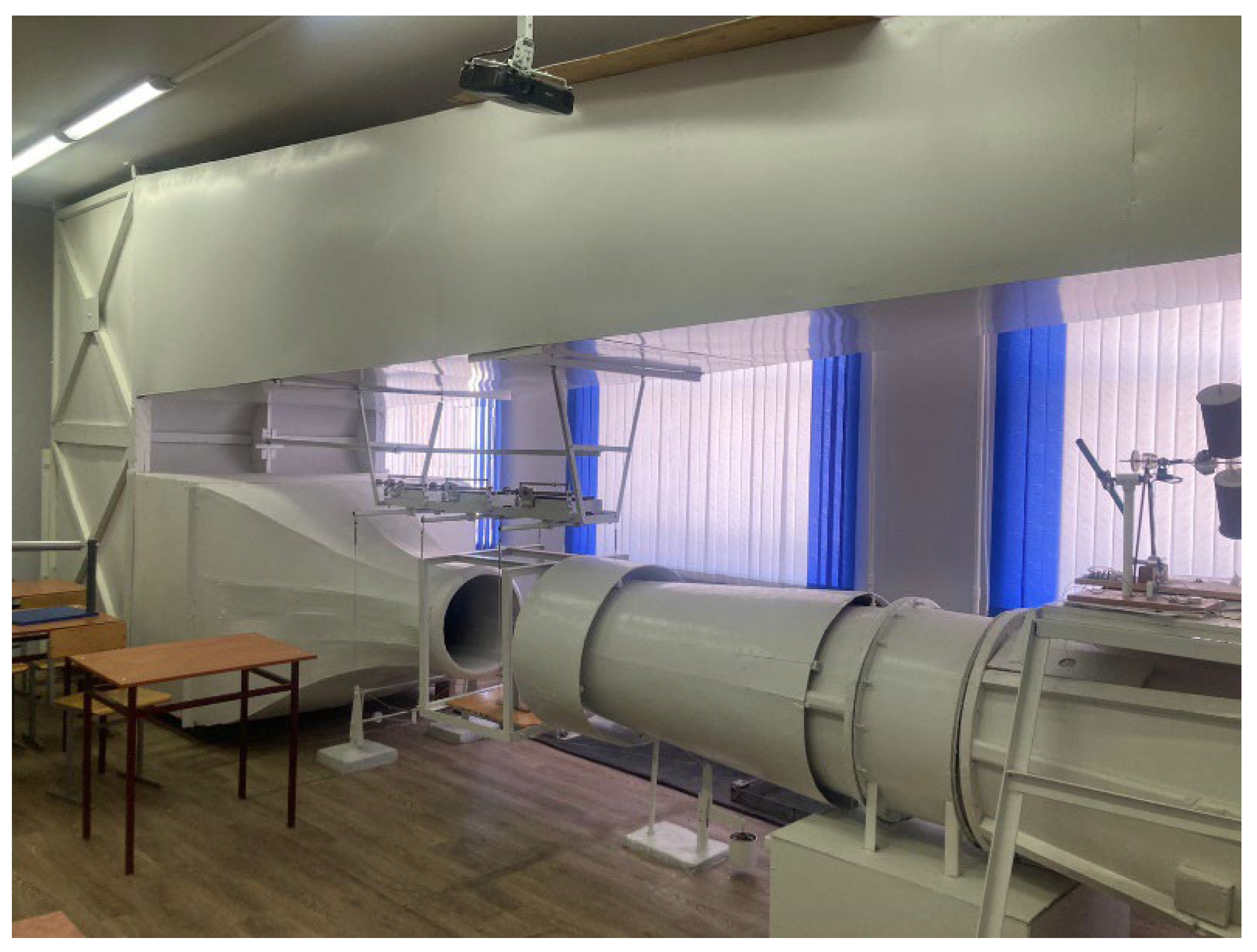
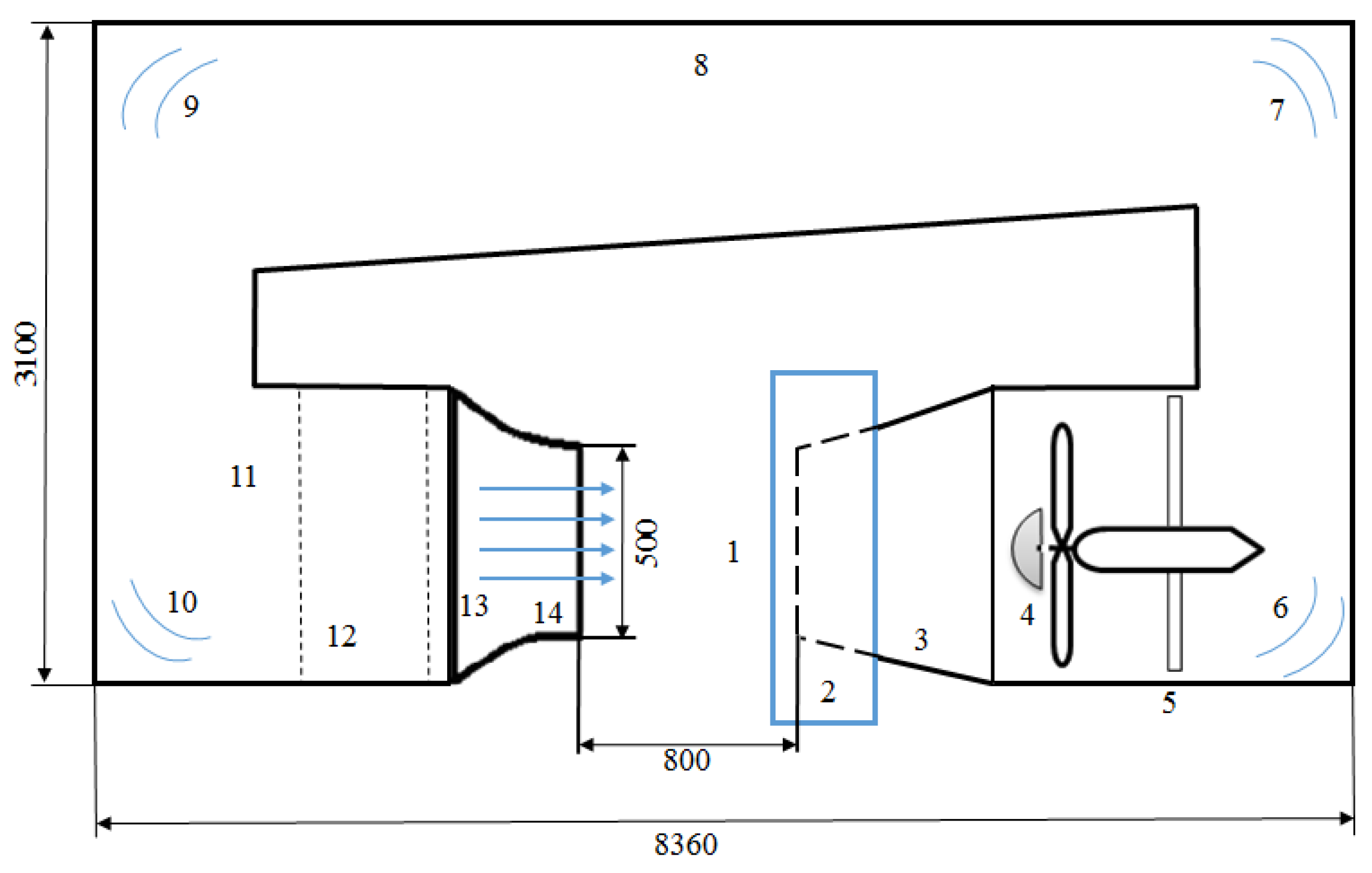
Experimental studies of aerodynamic characteristics were performed in the T-1-M wind tunnel shown in
Figure 3; the experimental setup diagram is presented in
Figure 4 [
29].
The wind tunnel operates by creating a controlled air flow that passes through the wind turbine model being tested, installed in the wind tunnel test section, which had a test section size of 0.5 m and a length of 0.8 m. The air flow velocity created by the fan was measured by a digital anemometer and varied from 3 m/s to 15 m/s. The rotation frequency of the wind turbine model was measured using an infrared optical tachometer, which recorded the passage of marks on the wind wheel.
To determine the torque of the wind wheel, a dynamometer method was used. One end of a nylon thread was attached to the model shaft, and the other to the dynamometer, fixed on the platform.
3. Experimental Results
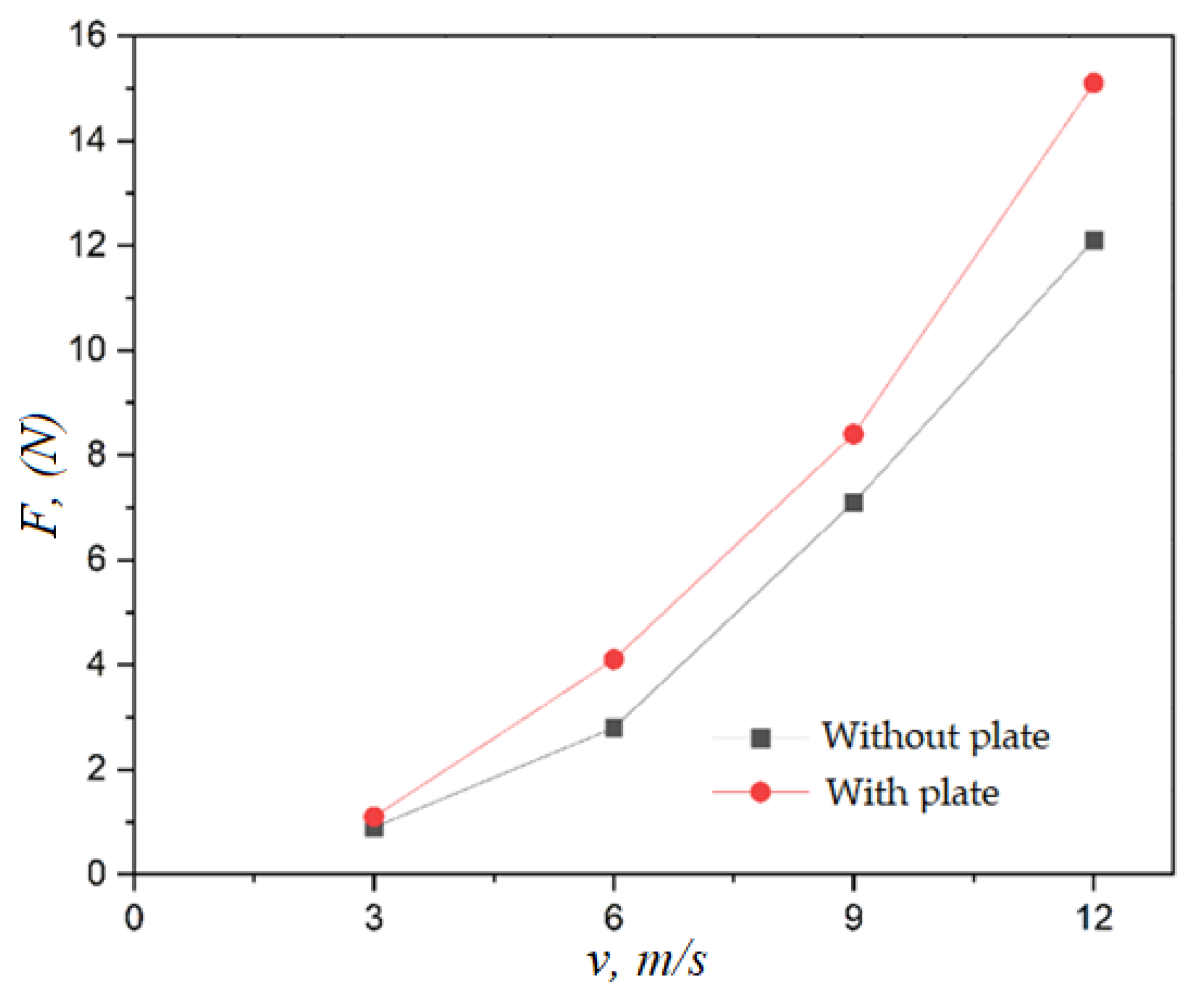
Figure 5 shows a curve of the thrust force values depending on the air flow speed.
The curve shows that the traction force increases with increasing wind speed. This increase is almost linear. At initial wind speeds (3–6 m/s), there is a relatively smooth increase in traction force. Then, at higher speeds (from 6 to 12 m/s), the traction force increases more intensively. These results demonstrate the importance of increasing the wind speed to improve the performance of a wind turbine since the traction force is directly proportional to the air flow speed, which ultimately affects energy production.
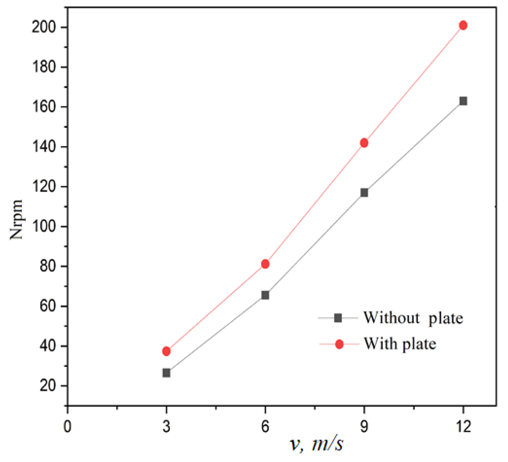
Also, the values of the number of revolutions of the wind wheel depending on the wind speed were obtained experimentally, as shown in
Figure 6.
As the wind speed increases, a linear increase in the rotor speed is observed. This indicates a direct dependence of the rotor speed on the wind velocity. With a wind velocity of 3 m/s, the rotor rotates at a speed of approximately 25 rpm. With a wind velocity of 12 m/s, the rotor speed reaches approximately 158 rpm. The data show that at low wind speeds (up to 6 m/s), the increase in the number of revolutions is less pronounced, whereas, at wind speeds above 9 m/s, the number of revolutions begins to increase faster, which may indicate an improvement in aerodynamic efficiency at high wind speeds. This curve is helpful in understanding the dynamics of the wind wheel operation with changing wind speeds and can be used to optimize the design of a wind turbine.
For the selected five wind speed values (3 m/s, 6 m/s, 9 m/s, 12 m/s, and 15 m/s), the starting torque of the wind turbine was measured experimentally. The results are presented in
Figure 7.
In the initial section from 0 to about 9 m/s, the breakaway torque increases almost linearly. This suggests that at lower wind speeds, the torque required to initiate rotation increases uniformly with increasing wind speed. After 9 m/s, the increase in the breakaway torque becomes more pronounced, with a steeper slope. This indicates that the forces acting on the blades begin to increase rapidly, which may be due to a non-linear increase in the aerodynamic forces as the wind speed increases. The maximum breakaway torque at the maximum wind speed (15 m/s) reaches about 4500 N. This shows the maximum value of the torque required to overcome inertia and initiate rotor rotation. The curve is important for understanding the performance of wind turbines at different wind speeds, especially at low speeds, when the moment of inertia is significant. This indicates that as the wind speed increases, the torque required to start the turbine increases significantly, which is important for designing turbines that can start efficiently, even in weak winds.
5. Results of the Mathematical Model
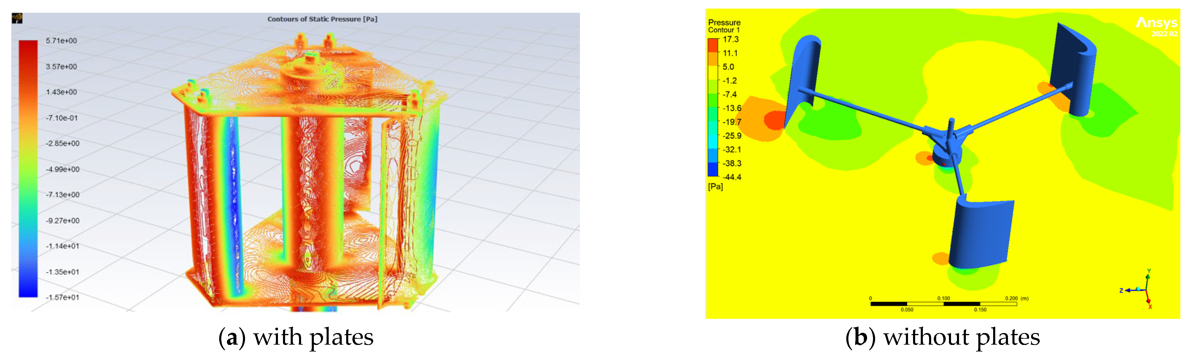
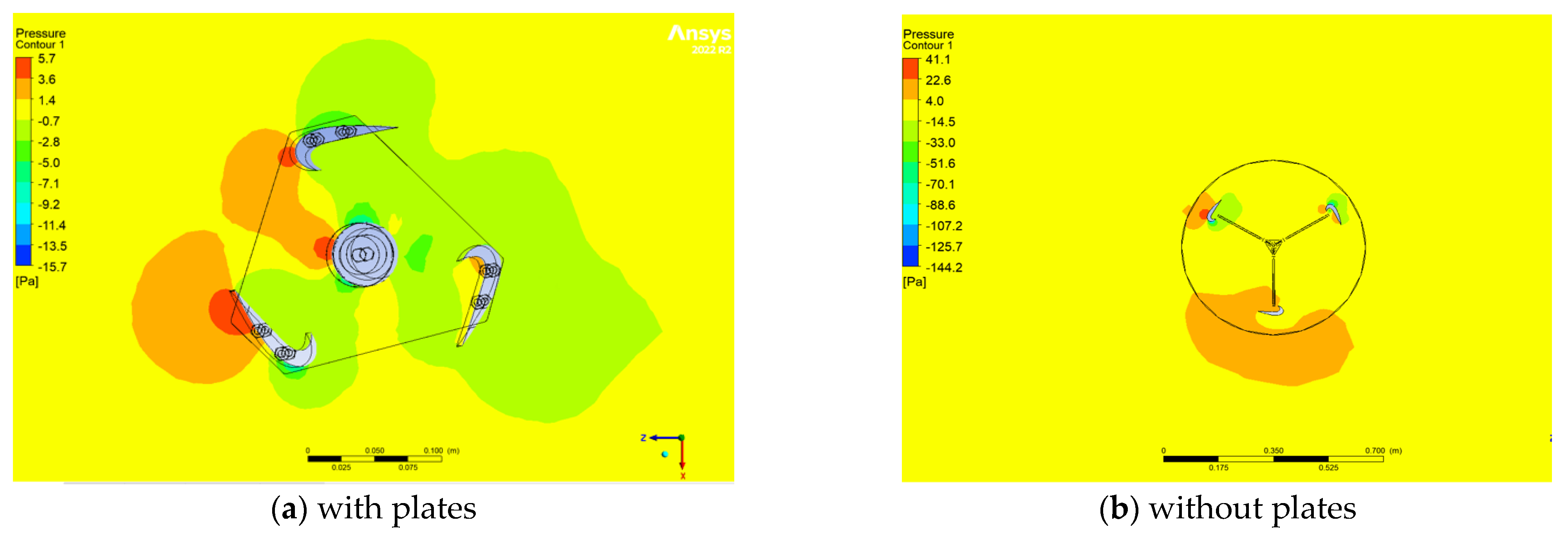
Figure 13 and
Figure 14 show contour plots of static pressure, allowing us to understand the physics of flow in Darrieus rotors. For the wind wheel, the blades were considered as moving blades. At a flow velocity of 3 m/s, the obtained results are a three-dimensional contour plot of the static pressure distribution around the vertical axis of the wind turbine (VAWT).
The figures show the static pressure distribution and aerodynamic interaction of a wind turbine with and without plates. In the first figure, (a) the use of plates leads to a more pronounced pressure gradient: high-pressure zones are concentrated at the leading edges of the blades located in the windward zone, which increases the lift. However, this also causes increased vortex formation behind the structure, which increases the turbulent wake and can affect the aerodynamic efficiency. In the second figure, (b) where there are no plates, the pressure distribution is more uniform, and the turbulence intensity is lower, which helps to reduce vortex losses and increase the stability of the structure. However, in this case, the lift can be reduced due to a less pronounced pressure gradient. Thus, the plates increase the aerodynamic effect on the blades but, at the same time, increase turbulence, while their absence provides a more stable pressure distribution and reduces vortex losses. The data highlight the aerodynamic design features that are important for optimizing turbine performance.
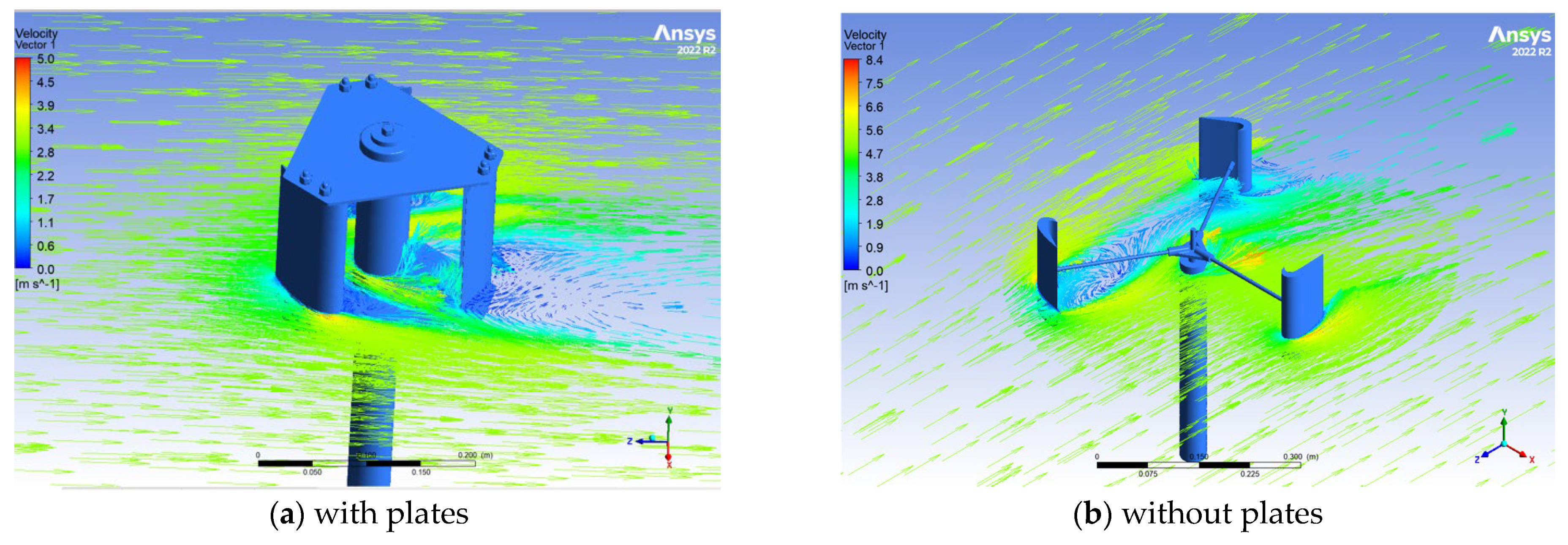
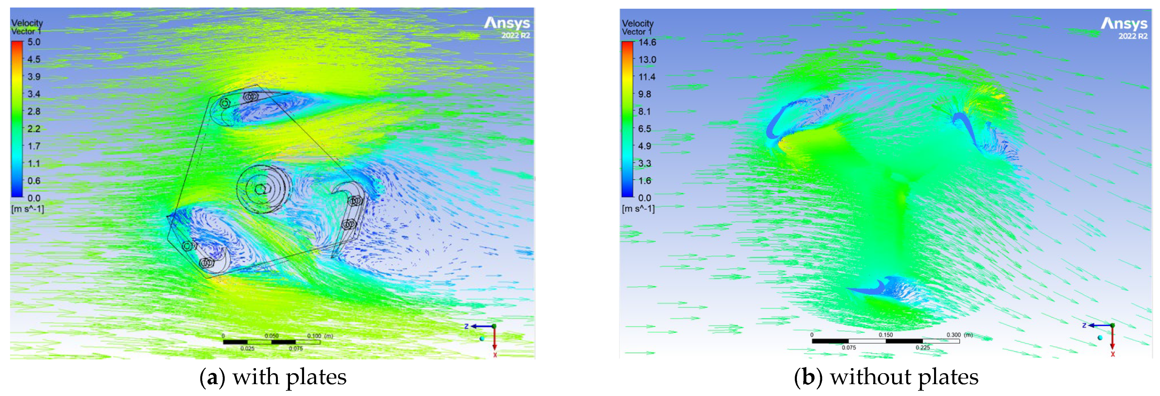
The provided
Figure 15 and
Figure 16 illustrate the distribution of velocity vectors around a three-bladed wind wheel based on mathematical modeling, as modeled in the Ansys program.
The presented visualization demonstrates the distribution of velocity vectors around a wind turbine with asymmetric blades, as created in ANSYS. The first figure, (a) shows the velocity field around the wind turbine structure with plates, where clear zones of air flow acceleration are visible along the surfaces of the blades and plates. The smooth velocity lines indicate the minimization of turbulence zones on the leeward side of the structure. The second figure, (b) shows the velocity field around a wind turbine without plates. Here, vortex formations behind the blades are clearly visible, caused by the increase in resistance in the leeward zone. The absence of plates leads to a more pronounced flow disturbance, which affects the overall aerodynamic efficiency of the plant.
Comparison of the curves shows that adding plates to the wind wheel design improves the flow characteristics, reduces the turbulent wake zone, and increases the rotation efficiency. At the same time, the wind wheel without plates demonstrates an unstable flow, characterized by increased turbulence and a decrease in the power factor with an increase in the air flow speed. These features emphasize the efficiency of the wind wheel design in creating lift and ensuring aerodynamic stability in various azimuthal positions.
For a more accurate assessment of the aerodynamic efficiency of the design, the power factor
was used, which is calculated using the following formula:
where
is the blade rotation power;
m is the number of blades;
—is the force acting on the blades during their rotation;
—is the angular velocity arising from the blade rotation,
—is the wind power, and
—is the rotor power.
Figure 17 below shows the change in the power factor
depending on the tip speed ratio (TSR).
The figure shows the dependence of the power factor on the total speed ratio (TSR) for wind turbines with different blade designs: with and without plates. The curve demonstrates that for all designs, increases with the TSR to a value of about 4, after which it decreases. Models with plates show higher values at all stages of operation compared to designs without plates, which indicates their improved aerodynamic characteristics. The experimental data (circles) are in good agreement with the numerical calculations (squares), confirming the reliability of the simulation. Small deviations are observed in the range of low TSR values, which may be due to experimental errors. The maximum value is achieved at TSR = 4, which corresponds to the optimal operating mode of the wind turbine. The results confirm that the use of plates increases the efficiency of the turbine, especially in the range of optimal TSR values.
6. Conclusions
In this study, experimental and numerical investigations were conducted on the aerodynamic characteristics of a Darrieus rotor with our proposed asymmetric blades in two structural configurations: with and without horizontal parallel plates. The obtained results made it possible to identify the effect of the plates on the rotor efficiency at low wind speeds and determine their effect on the key aerodynamic parameters. The experimental data showed that the rotor with horizontal parallel plates demonstrates a higher power factor () and better self-starting compared to the rotor without plates, and at a wind speed of 3–6 m/s, the rotor with plates showed 18–22% higher torque, which facilitates the start and stable operation of the turbine. The CFD numerical modeling confirmed that the presence of horizontal plates helps to stabilize the air flow around the blades, and the vortex structures behind the blades of the rotor with plates are less pronounced, which reduces aerodynamic drag and minimizes energy losses. Parallel plates create a directional flow effect, increasing the lift of the blades and contributing to a more efficient conversion of wind energy into mechanical work. In the case of a rotor without plates, the CFD modeling revealed significant low-pressure zones and strong turbulence behind the blades, which leads to an unstable flow and increased aerodynamic losses. As the wind speed increases above 9 m/s, the difference in efficiency between the two designs decreases, but at weak winds, the rotor with plates continues to demonstrate better performance.
Thus, it was established that the Darrieus rotor with our blades and horizontal parallel plates demonstrates higher efficiency at low wind speeds compared to the rotor without plates. The performance improvement is associated with flow stabilization, reduced vortex losses, and increased lift force, as confirmed by both experimental and numerical studies. The obtained results indicate that the Darrieus rotor with plates and the proposed asymmetric blades is a promising solution for small-scale wind energy systems operating under low and variable wind conditions.


 ,
, 


