Article

RFID Technology Serving Honey Bee Research: A Comprehensive Description of a 32-Antenna System to Study Honey Bee and Queen Behavior

USDA-ARS Bee Research Laboratory, Beltsville, MD 20705, USA
*
Author to whom correspondence should be addressed.
Appl. Syst. Innov. 2021, 4(4), 88; https://doi.org/10.3390/asi4040088
Submission received: 24 September 2021 / Revised: 1 November 2021 / Accepted: 2 November 2021 / Published: 9 November 2021
(This article belongs to the Section Information Systems)

Abstract

:
The fields of electronics and information technology have witnessed rapid development during the last decades, providing significant technical support to the field of biological sciences. Radio-Frequency Identification (RFID) technology has been used to automate the monitoring of animal location and behaviors in a wide range of vertebrate and invertebrate species, including social insects such as ants and honey bees (Apis mellifera L.). This technology relies on electromagnetic fields to identify and track transponders attached to objects automatically. Implementing new technologies to serve research purposes could be time consuming and require technical expertise from entomologists and researchers. Herein, we present a detailed description on how to harness RFID technology to serve honey bee research effectively. We describe how to build and operate a 32-antenna RFID system used to monitor various honey bee behaviors such as foraging, robbing, and queen and drone mating, which can be used in other social insects as well. Preliminary data related to queen nuptial flights were obtained using this unit and presented in this study. Virgin queens labeled with ≈5 mg transponders performed multiple (one to four) nuptial/orientation flights a day (9 a.m. to 5 p.m.) ranging from 8 to 145 s each. Contrary to virgin queens, no hive exit was recorded for mated queens. At full capacity, this unit can monitor up to 32 honey bee colonies concurrently and is self-sustained by a solar panel to work in remote areas. All materials, hardware, and software needed to build and operate this unit are detailed in this study, offering researchers and beekeepers a practical solution and a comprehensive source of information enabling the implementation of RFID technology in their research perspective.

1. Introduction

The recent and remarkable advance in technology, particularly in artificial intelligence and information technology, has provided entomologists and scientists with powerful tools to conduct close and more surgical monitoring of insect behavior or other organisms [1,2,3]. The ability to acquire continuous and accurate data related to a given organism provides a better understanding of this organism in its ecosystem. Recently, the field of honey bee research has benefited and utilized many sophisticated electronic devices and sensors, offering a closer and more sustainable monitoring of honey bee biological traits and behavior [4,5]. Some of these sensors were used to obtain continuous and accurate data of the hive’s inner temperature and humidity throughout the season [6,7], while others were highly sensitive electronic scales used to assess the daily weight fluctuation of honey bee colonies [8]. Electronics were not only used to track honey bee biological traits but also to monitor bee parasites’ load and behavior within the hive. A recently published computer vision system allows the estimation of Varroa destructor infestation within bee colonies by utilizing a deep learning process [9]. On the same parasite, a recent study described the successful use of electropenetrography (EPG) signaling to characterize the feeding behavior of female mites on honey bee pupae [10]. Harmony Radar technology was also used to track the activity of the Asian yellow-legged hornet (Vespa vilutina) and to characterize the impact of a honey bee microsporidian pathogen (Nosema ceranae) on honey bee flight and orientation in the field [11,12,13]. This technology consists of tracking a transponder fix on an insect, which can be exited and located by a stationary horizontally scanning radar system [14].
On social insects, many studies have used Radio-Frequency Identification (RFID) technology as a tool to improve our understanding of their behavior and way of life [15,16,17]. This technology was particularly efficient to monitor wild bee species closely, more appropriately called non-Apis bees [18,19,20], as these highly diverse bee species are poorly known, and close access to their nests is challenging. Bee behavioral studies not only provide fundamental comprehensions of bee sociality but are also critical to shed more light on the physiological response of these social insects to a wide range of biotic and abiotic stressors and how these stressors shape bee behavioral responses. For instance, RFID technology was used in colonies of bumblebees (Bombus impatients) to study the effect of an endoparasite (Conopidae, Diptera) on their biological traits such as growth and mortality, as well as the parasite–ecology synergy on bumblebee foraging performance [21]. On honey bees (Apis mellifera L.), RFID technology was used to study the effect of sublethal concentration of neonicotinoids facing honey bees in the field on their foraging performance and mortality [22]. It has also been used to observe queen mating behavior and monitor the frequency and duration of the nuptial flights [23]. Despite the recent increase in RFID techniques in honey bee research, a comprehensive description of an RFID unit adapted to the honey bees’ particular characteristics is still missing. Currently, no “off-the-shelf” RFID unit exists or is commercially available to accommodate honey bee research. Researchers planning to track bees by RFID will have to build their own unit whether they need to monitor one single beehive or more. The main requirements and expectations of an efficient RFID unit to be used in honeybee research are as follows: (1) its ability to accurately detect bees at the hive’s entrance and properly transmit their signals, (2) the ability to monitor simultaneously multiple hives to provide meaningful statistical analysis on multiple technical and biological replicates, (3) prolonged operation in rural areas where no electric grid is available, (4) easy to deploy to the field, and (5) cost-effective. Optimizing RFID techniques for bee research is time consuming and requires innovative and multidisciplinary skills. Therefore, a comprehensive source that details all RFID technicalities and software use is necessary and would be a valuable source for honey bee researchers and beekeepers alike.
In this study, we provide a comprehensive description of how to build and operate an RFID 32-antenna system to study honey bee behavior in the field and monitor queen nuptial flight. The unit detailed in this study meets all the previously described requirements and can accommodate relatively large-scale experiments reaching up to 32 monitored colonies simultaneously. We describe here basic data collection and other technicalities related to tag naming and operating this unit with a power grid in remote areas using solar energy.

2. Materials and Methods

In general, tracking objects by RFID requires an RFID reader, RFID antennas, and a portable computer for data collection and communication with the RFID reader (Figure 1). The unit described in this study is composed of (1) the RFID electronic hardware, including the reader, antenna hubs, adapter kit, and wiring, as well as a laptop, to continuously collect the data, (2) antenna cables that transmit the transponders’ signals from the hive entrance to the antenna hubs and subsequently to the reader itself, (3) a generator that is the primary power source for the whole unit is needed when this unit operates in remote areas with no electric power available close to the apiary or the experimental site and (4) a solar panel whose role is to charge the aforementioned generator (Figure 2). This unit is designed to operate in remote rural areas where no electric source is available and most of the large-scale bee operations and apiaries are usually located. As a practical and economical solution for beekeepers, we have accommodated the equipment and devices of this unit in honey bee hive boxes. However, any other well-ventilated boxes can be used for this purpose.
There are two ways to operate this unit, either by running a licensed software (Speedway Connect, Table 1) within the RFID reader itself and collecting the data on a USB thumb drive plugged into the reader or by running a free, open-source software (ItemTest, Table 1) on a laptop computer connected through an Ethernet cable to the reader (Figure 2). The first option is more reliable and does not require the laptop to constantly be connected to the unit and running while operating, significantly reducing the energy consumption from the power generator, as shown in Figure 2. Below is a detailed description of the unit’s components.

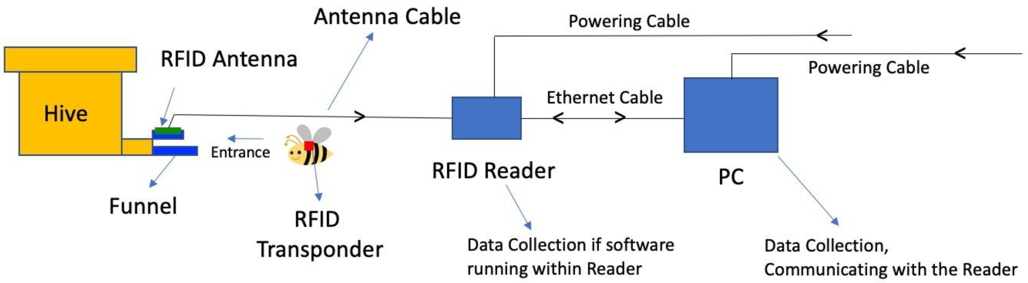
2.1. Electronic Hardware

The central item of this unit is the processor or reader, whose role is to capture various signals coming from the antenna cables and process them accordingly, and then send them to the computer. In this unit, we used the Speedway Revolution Reader manufactured by IMPINJ (Impinj Speedway R420 UHF RFID Reader USA/FCC “4 Port”) (Table 1). This reader by itself can only accommodate four antennas, as it has only four ports available, which means without any modification or extension, this reader can only monitor four honey bee colonies at once (Figure 3b). As a cost-effective solution, if envisioned experiments only require four or fewer antennas, the antenna hubs and the adaptor kit may not be required. In this setup, the four antennas coming from the beehives can be plugged directly into the four available ports of the reader (Figure 2 and Figure 3). The reader will operate as expected with four antennas but well below its maximum capacity of 32 antennas. Therefore, to maximize the benefits and amount of data generated by this reader, we based the design of this unit on the reader’s maximum capacity of 32 antennas.
For this purpose, two additional items are required: an adaptor kit and four antenna hubs that can bring up the reader’s capacity to a total of 32 antennas, as shown in Figure 2. That said, this unit does not need to always operate on 32 antennas. It can cover all experimental requirements, going from one single antenna to a full 32 antennas (maximum capacity of this unit). There are a few aspects and specifications related to the performance of this reader, which is controlled by the software that will be further discussed in this study.

2.2. Cables and Antennas

All cables required to build and operate this unit are available on the market and can be summarized as follows: (1) power cables used to power the reader and the laptop, (2) a VGA cable to link the adaptor kit to the reader, (3) ethernet cables linking the adaptor to each hub, (4) radio-frequency cables linking the reader to each hub for signal transmission from the beehive, and (5) antenna cables that transmit the signal from the transponder (at the beehive entrance) to the hubs (Figure 2 and Figure 3b). The 1800 W power generator is provided with all necessary cabling to operate, including a charging cable from the solar panel to the generator and a cable for charging the generator directly from an electric outlet.
The second crucial part of this unit is the antenna, whose role is to capture the bee tag (transponder) signal at the hive entrance and guide it to the hub and subsequently to the reader. There are different types and sizes of antennas commercially available; however, the 5 dBi precision antenna is the most adapted for our purpose (Table 1). In order for the antenna to accurately detect and transmit the bee entry/exit from the hive, funneling bees through an entrance tunnel is required, as shown in Figure 1 and Figure 3a.

2.3. Transponders or Tags

A transponder is typically an element that sends and receives the optical signal from an antenna. Transponders are usually characterized by their data rate capacity, size, and the maximum distance of signal transmission. The size of the tag is crucial, as bees can easily be burdened and disabled by their weight and size. In our case of tracking honey bees, the smaller the tag, the better. In this study, we used the Hitachi transponders (2.5 × 2.5 × 0.4) mm, which are considered among the smallest and lightest tags available on the market within a reasonable price range. If a smaller transponder is desired or required (i.e., monitoring smaller bee species), users can opt for the UHF RFID tags produced by muRata with (1.5 × 1.2 × 0.5) mm dimensions at a higher cost.

2.4. Modification of Hive’s Entrance

For the antenna to capture the tag’s information and read it, bees carrying the transponder must be funneled and oriented through a tunnel that should ensure proper exposure of the tag to the antenna while bees pass through the hive entrance. As a general rule, the bigger the antenna size is, the farther it reads and responds to the transponder. As for bee monitoring, precision in detecting the tag in a small 3D space and close distance are prioritized. The antennas used in our study are small 5 dBi precision antennas (Table 1), which can only identify objects in close proximity. Therefore, we designed a movable tunnel that can be easily placed at the hive entrance and detached when no monitoring is needed and replaced by the traditional hive entrance door (Figure 3). The antenna is placed midway at the top of the tunnel and covered with a 1.2 mm plexiglass sheet protecting against rain and other weather conditions. The tunnel’s width is crucial and should provide enough space to allow smooth bee passage and ventilation of the hive. The tunnel’s dimensions in our design were width = 4 cm, height = 1.2 cm, and length = 10 cm (Figure 3a).

2.5. Power Source and Solar Panel

The generator is the primary power source for this unit when operating in remote areas. Throughout the experiment or the reading cycle, it must constantly sustain the reader and the computer (if the software operates on the computer and not the reader). The simple equation for choosing a power generator is that the latter must be able to acquire more or equal charge than what the unit requires while operating under full capacity. We powered our unit using two different options described in Table 1: (1) using an 1800 W power generator linked to a 150 W solar panel, or (2) using a 12 V battery (100 Ah) with a 600 W inverter. The generator or battery can be bypassed if the hive box containing the RFID electronic hardware (Figure 2) operates close to a power grid and is directly powered via an electric outlet.

2.6. Software and Computer

The main objective of this unit is to provide reliable data related to honey bee activity promptly with minimum computing capability from the user end. Therefore, we have opted for the simplest way to operate and collect data from this unit without using terminals or command scripts and language. The freely available software (MultiReader for Speedway Gen2 RFID readers) was used to identify and rename the transponders (Table 1). There are two options for operating the unit and collecting the data: (1) either by running a licensed software (Speedway Connect SW, version 6.2.2.240, Table 1) directly on the reader itself, which excludes the need for the laptop to stay connected to the unit or by running a freely available software (ItemTest, version 2.3.0, Table 1) on the laptop that must constantly stay connected to the reader and in running mode while the experiment is ongoing. All three software were tested and demonstrated in this study using a computer system operating under Windows 10.

2.7. Data Collection

The final step is the data collection that was conducted using both the ItemTest software mentioned above (freely available and running on the laptop) and the licensed software (Speedway Connect), which runs within the reader itself and does not require the laptop to stay connected to the unit. In the second case, a laptop is only required to upload the Speedway connect software on the reader using an “http://” web page via an Ethernet cable and activating and deactivating the software within the reader at the beginning and end of the experiment. Once the software is activated and the unit is operating, the laptop can be disconnected from the reader and data will be collected through a USB drive directly connected to the reader (Figure 1 and Figure 3b).

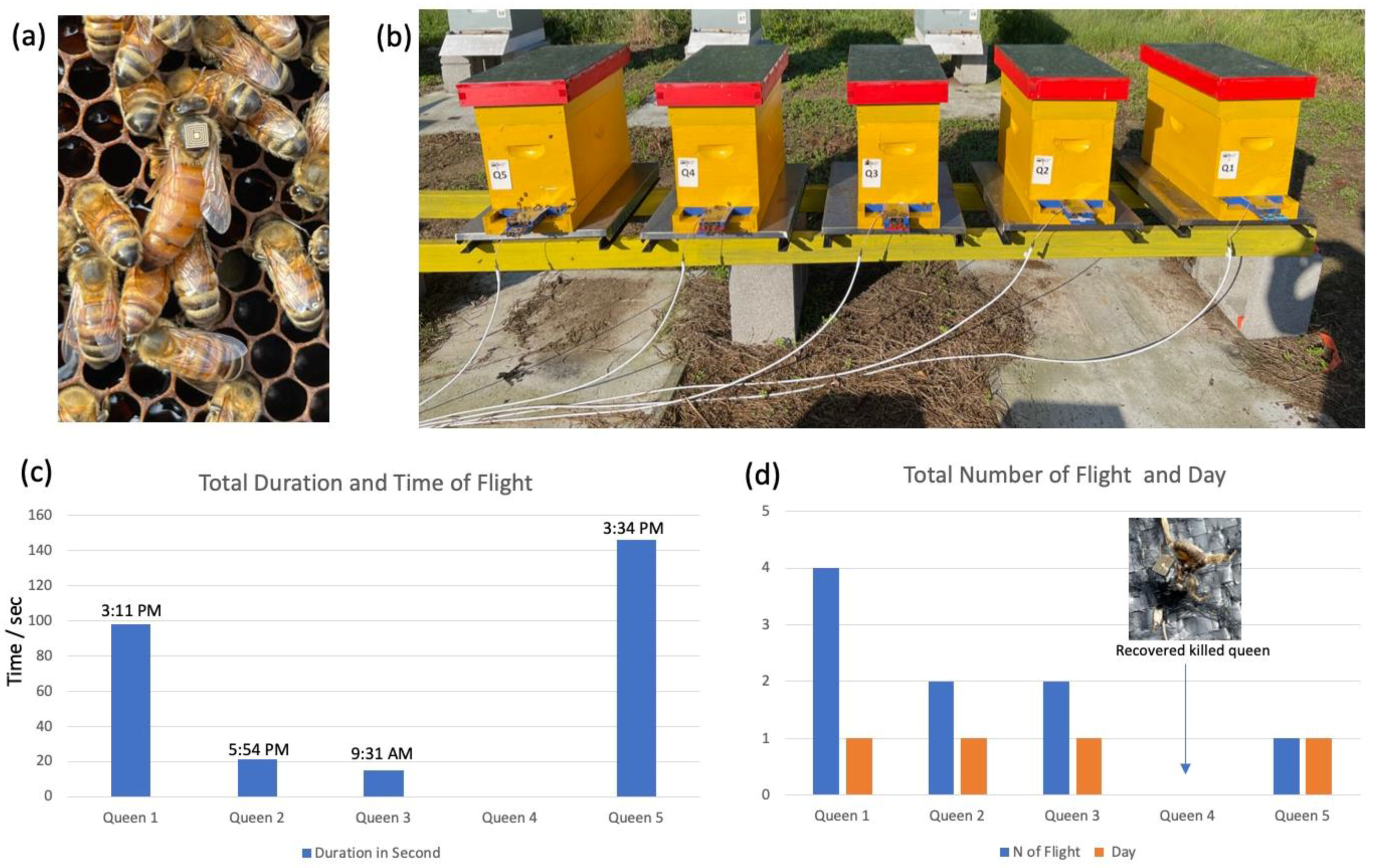
2.8. Queen Nuptial Flight Monitored by RFID

The performance and accuracy of our unit were tested under field conditions to track the nuptial flight of 10 honey bee queens. In mid-August 2021, ten queenless honey bee nuclei were prepared and fed for queen introduction. One funnel (Figure 1) was placed at each nucleus’ entrance with a cable connecting the antenna to the unit. Ten honey bee queens (five virgins and five fully mated) were each labeled with a transponder. Transponders were glued by gently applying a tiny dot of super glue on the central area of the dorsal thorax segment of the queens. For this purpose, a regular queen marking cylinder was used. Queens were individually kept in cages for approximately 20 min to allow the glue to dry to ensure proper positioning of the tags and were subsequently introduced to the nuclei. Contrary to virgin queens, mated queens are not expected to perform any nuptial flight under normal circumstances. This behavior allows mated queens to function as a negative control to help evaluate the proper function and signaling of the unit. The queens were introduced on the 20th of August, and this preliminary experiment lasted 15 days.

3. Results

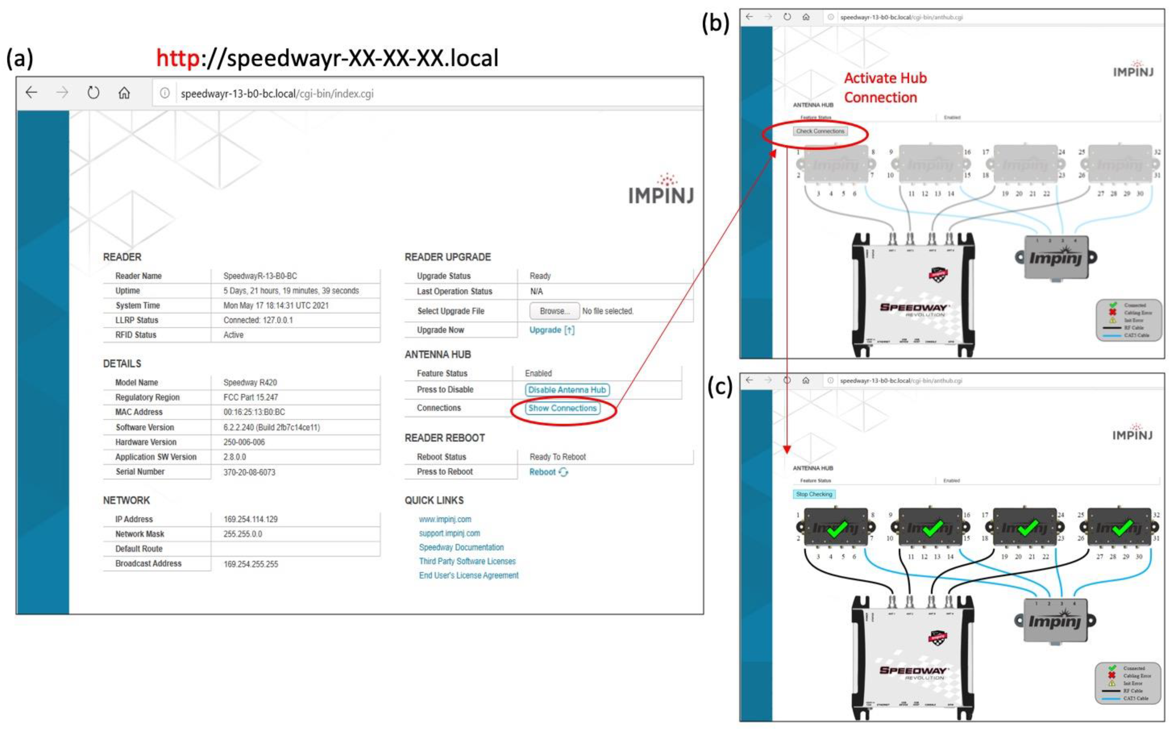
3.1. Unit Activation

Once the unit is assembled and ready to operate, the user must activate the connection between the reader and the four hubs. Communication with the reader was achieved using a web browser (Internet Explorer) and typing the reader’s address, which is composed of the reader’s name and serial number printed on the reader (http://speedwayr-XX-XX-XX.local) (Figure 4a). In our case, the reader’s serial number was (13-b0-bc). On the reader’s main page, connectivity can be visualized by pressing “Show connections” (Figure 4a) followed by “Check connections” (Figure 4b). Proper connection of all hubs is indicated by a green checkmark (Figure 4c).

3.2. Transponder and Antenna

The most sensitive process of the RFID system is a proper transmission of an accurate signal from the bee (queen, drone, worker) carrying the transponder to the antenna fixed on top of the tunnel at the hive entrance (Figure 3a). The electromagnetic fields of the antenna can be significantly disturbed by metal objects. Therefore, it is recommended to avoid using nails and screws in close proximity to the antenna’s electromagnetic field. Our optimization and testing results showed that the antenna used in this unit (small precision 5 dBi, Table 1) could only read transponders in a range of 0–1.5 cm and failed or lacked accuracy and consistency in detecting tags at >1.5 cm. Moreover, the antenna could adequately read the tagged bees through the plexiglass in its reading range, whether placed above or below the bee’s path to the hive. The translucent plexiglass used on top of the tunnel is recommended, as it allows the user to visually check the proper positioning of the antenna and observe any abnormality in bee behavior while passing through. The tunnel described in Figure 3a can fit both five-frame nuclei and full ten-frame Langstroth hives. In case of overpopulated hives requiring larger entrances, two tunnels per hive can be used. Concerning the transponder itself, the average weight of the UHF Hitachi tags used to label queens in this study was approximately 5 mg, which represents ≈5% of the average weight of a honey bee worker (0.1 g) and <3% of a queen’s weight, which may range between 170 and 230 mg.

3.3. Transponder Renaming

Social and behavioral experiments require, most of the time, the individual identification of bees. Therefore, the ability to rename each tag with an appropriate code is crucial. Usually, when sold to users, transponders come with a universal code of dozens of digits and letters. In most RFID software and language, the transponder name, effectively the name of the tracked bee in a given experiment, is always indicated by the abbreviation “EPC,” which stands for Electronic Product Code (Figure S1). It is recommended to always name the transponders prior to gluing them to bees. For this purpose, the MultiReader Software was opened, and after ensuring that the reader was online (Figure S1a), an inventory of the transponders was performed simply by clicking the “Start Inventory Run” button and scanning the tags through any available antenna, as shown in Figure S1. Once the transponders appeared in the active box and the inventory stopped, a right-click on the EPC of the transponder prompts a new window, “EPC Actions,” which gives the option of “Change EPC.” A new window “Change Tag EPC” will appear, allowing the insertion of a new EPC and its writing on the tag, Figure S1b. When ready to rename a tag, and the “Write Tag” button is clicked, the tag must be scanned through the antenna to copy the new information into the transponder’s internal memory. A confirmation message will be displayed if the renaming operation is successful, as shown in Figure S1b.

3.4. Data Collection and Treatment

3.4.1. Using ItemTest Software

Data collection is completed using ItemTest software, which generates a simple (.csv) excel file that can be saved on the computer connected to the unit once the software is stopped. The data collected and available in this file can be modified through the ItemTest Software by changing the reader’s settings (Figure S2). By default, the software provides sufficient information related to bee activity. The three first columns in the excel file contain the critical data one would be interested in seeing: the date and time, the EPC (name of the bee), and the antenna number (hive number) (Figure S2c). Note that the excel file in Figure S2 shows two different EPC names, the manufacturer/original name of a tag (3504AD57900542F147D38463) and a second tag renamed as bee number: (1002). The data reads as follows: on the 18 November 2020, bee number 1002 entered (or departed) colony number 1 at 17:02 and 16 s (Figure S2c).

3.4.2. Using Speedway Connect Software

This setup was determined to be safer in terms of data collection but would require purchasing a license key for Speedway Connect (Table 1). In this case, the data can be collected directly from the reader as a (.csv) file using a USB flash drive plugged into the reader, and the software runs on the reader itself and not the laptop. This method of operating the unit provides higher power efficiency, as no computer needs to be powered during the experiment and data are not saved on the computer, which could fail during inclement weather conditions and prolonged use. Once purchased, the software was installed into the reader using the “Browse” button on the reader’s main page (Figure 4a). After installation, the Speedway Connect software was accessed via the Internet Explorer browser at the address (https://speedway-XX-XX-XX.local) and activated as detailed in Figure S3. Speedway Connect generates an output data file (.csv file) similar to ItemTest but saved on a USB drive plugged directly into the reader.

3.5. Power Source

3.5.1. Generator Capacity

The charging capacity of the solar panel is not absolute and should be evaluated based on the location of the panel (forest, open landscape), the seasons, and climate conditions (sunny or cloudy conditions). One solar panel can provide up to 150 W of charge to the generator, and if more charging power is needed due to higher energy demand from the generator, additional panels can be added and connected to the previous panel. According to our testing, the generator used in our study (1800 W) was able to power the whole system (including the laptop) without been charged for a period of ≈48 h prior to depletion. This period expanded to a full week when the software was run within the reader, bypassing the laptop and its power consumption. On a smaller scale, we found that the power required to activate four antennas and the computer running the ItemTest software was approximately 45–60 W according to the read on the generator’s screen. However, at full capacity of 32 antennas and the software running within the reader (excluding the laptop), the unit consumed only 11–13 W and was easily self-sustained by recharging from the solar panel. It is strongly recommended to provide proper ventilation windows in the box’s body for the generator to avoid overheating. Despite being relatively expensive (US $2500/Table 1), the generator is a good off-the-shelf solution to power the unit.

3.5.2. V Battery with Invertor (600 W)

The second powering option proposed in this study (12 V battery + 600 W inverter) is much more cost-effective (US $360/Table 1) and was revealed to provide continuous and adequate power for a unit similar to the generator. In our setup, in which the software ran within the Speedway, the wattage required to operate the unit was minimal (<13 W) and fully sustained by the 12 V rechargeable battery. It should be noted that the actual wattage consumption of the unit, despite being low, is not the only relevant value to be considered. If incorporated, the battery storage capacity is crucial, as it should be capable of powering the unit overnight when solar energy is unavailable. This option adequately powered the unit during our initial testing on queen nuptial flights conducted during summer between August and September.

3.6. Preliminary Data: Queen Nuptial Flight

The RFID unit described in this study was deployed to one of our apiaries located in Beltsville, MD, USA and used from 20 August to 5 September 2021. Data were collected as excel files from the thumb drive as described previously in the materials and methods (Data collection). Our unit recorded no activity for any of the five mated queens (Queens 6 to 10), with only virgin queens attempting nuptial/orientation flights, as shown in Figure 5. All queens conducted their single or multiple flights within a single day (Figure 5d) with various flight durations ranging from 8 to 145 s. Our data showed a single exit of Queen 4 on 26 August at 8:53:08 a.m. with no re-entry, indicating a rejection of virgin queen introduction. This queen was recovered from the hive main entrance a few days later, as shown in Figure 5. The number of flights varied between colonies from one to four flights. Three out of the four flights were conducted in the afternoon (3–5 p.m.), while the fourth was in the morning at 9:31 a.m., as shown in Figure 5. On 14 September, oviposition was checked and documented for each of the queens that performed outdoor flights. Aside from the rejected queen (number 4), all other queens (Q1–5) have laid eggs and initiated brood production.

4. Discussion

The RFID unit discussed in this study required intensive interdisciplinary collaboration and consultation with specialists and experts from various disparate fields of science. As there is no off-the-shelf RFID unit available to monitor honey bee behavior, this study can provide valuable help and tools for entomologists looking to include RFID technology in their research programs. As stated previously, RFID tracking technology for bees and other insects has been used in different studies [24,25,26,27]. Nevertheless, few of these studies offered technical details related to their RFID methodology [4]. The main advantages of this unit are its small size, easy deployment to the study site, ability to monitor up to 32 honey bee colonies simultaneously, and operation with or without a power grid, which allows tracking bees in managed colonies located in remote and rural locations.
When located off-grid, the power source remains the most critical component in such a unit. Our study proposed and tested two options for users to power their unit. Nonetheless, using a 12 V battery with an inverter remains significantly cheaper than purchasing an 1800 W generator. We successfully powered and operated this unit 24/7 (using option two described in Table 1) from July to September and did not experience any technical difficulties related to the power supply. Although this unit would not typically be used in autumn and winter, adequate and continuous battery charge remains to be tested. The data obtained from RFID bee tracking systems should be carefully revised and potential misreads discarded prior to data analysis. Misreading usually occurs when high numbers of bees per colony are monitored simultaneously and can be addressed using an adjusted algorithm [28]. Other instances of misreading or constant tag reading could happen when tagged-worker bees are stationary (e.g., defending, ventilating, and cleaning the entrance) within the reading range of the antenna. These instances usually cause prolonged exposure of the transponder to the antenna, which is a concern that can be addressed by changing the software reading parameters to “Single Read” or “Oppress Read” for a desirable number of seconds, allowing tagged bees to vacate the scanning field of the antenna. Another challenge reported when using RFID tracking is the loss of the transponder or tag [29]. Transponders are usually fixed on the dorsal thorax segment of the bee using standard super glue. The use of small-size transponders and careful gluing on bees should help to minimize tag loss. The RFID method was revealed to be an effective technology to replace traditional observation of honey bee foraging activity, which is considered laborious and significantly less accurate. RFID tracking was used to identify sublethal effects of neonicotinoids on honey bee foraging behavior and homing [30]. Slightly larger tags (3 × 3 × 0.08) mm than those used in our study were used in a recent study that showed higher bee foraging activity prior to precipitation [31]. The transponder size can vary based on the size of the monitored insects and their lifting capacity.
Nonetheless, the transponder size used in this study (2.5 × 2.5 × 0.4) mm was found to be optimal to monitor queen nuptial flights. All four surviving queens in our preliminary experiment were able to conduct their mating flights and successfully initiated oviposition indicating no burden or disability caused by these tags. The average weight of the tags used in our study was ≈5 mg, which is less than 3% of the average queen weight (≈190 mg). Previous studies have indicated that effective tags should represent less than 5% of the body mass [32] or 2% only for flying animals [33]. Honey bees were successfully tracked by harmonic radar system using transponders weighing between 12 and 15 mg [13]. Despite these estimations, the data obtained from our study clearly indicate that virgin queens of ≈190 mg were able to perfectly perform their nuptial flight while tagged by 5 mg Hitachi tags described in this study. However, the quality of the mating process remains to be studied and investigated. If other types or sizes of transponders are used [34], the height of the funnel should be adjusted to capture the transponder’s signal by the antenna adequately. The harmonic radar system is one of the remarkable types of technology used in tracking and monitoring bee flight behavior in the field [13]. While monitoring by RFID generates limited information related to the bee entry and exit of the colony, the harmonic radar system provides detailed information on bee trajectories and foraging behavior. However, this system would require a clear line-of-sight at all times between the radar and the tracked object, and its transponders are not uniquely identified [13]. The user would have to determine which technique to use based on the nature of their experiment and the data expected to obtain.
Despite providing valuable data on honey bee foraging behavior, previous studies used immobile RFID equipment fixed in on a single hive or location and relied on the availability of electric power. However, this study presents a compact 32-antenna RFID unit, which can monitor with high precision 32 honey bee colonies simultaneously, is easy to deploy, and is energy self-sufficient.
In conclusion, our data show that the design and operation of this unit have met all the requirements needed for an RFID unit to monitor honey bees. This unit provided highly accurate data on ten colonies simultaneously, was self-sustained for months by solar energy, and required low wattage to operate. Thus, the RFID unit described in our study would be a valuable tool to facilitate and improve the use of RFID technology in honey bee and social insect studies. Our next step is to make this unit WIFI-enabled, which will allow remote access to the data by transmitting the latter from the field directly to a Cloud Platform. This has already been studied in more developed systems such as the Columbia River Salmon PIT tag program and the ETAG RFID Open Science System in Oklahoma for bird monitoring.

Supplementary Materials

The following are available online at https://www.mdpi.com/article/10.3390/asi4040088/s1, Figure S1: Process of scanning and renaming transponders using the RFID unit’s computer. (a) The interface of the MultiReader software with scanned tags (red color). The display of blue dots indicates the active connection between the unit and software for both antennas and the reader. (b) Visualization of the new window for tag renaming prompted by right-clicking on the transponder’s name (EPC Value). A confirmation message must be displayed to ensure proper name recording in the transponder’s internal memory. Figure S2: Basic operation of the ItemTest software running on a laptop connected to the RFID unit. (a) Active connection of the unit to the software for data transfer and communication. (b) Results of tag inventory obtained by clicking the “Play” button (top left) to initiate tag scanning (highlighted in gray). (c) Final output generated by ItemTest as an excel file (.cvs), which comprises the date and time of the bee activity (Timestamp), name of the bee (EPC), and its hive (Antenna). Figure S3: Interface of the preferred software for this unit (Speedway Connect). (a) shows accessing the software through a webpage using the reader address (https://speewayr-xx-xx-xx.local). The red tag indicates the software is not running. (b) shows running the software by pressing the “Status” button followed by “Apply.” (c) Software running when the “Status” tag is green and flashing lights on both hubs and reader are observed. The software interface comprises additional parameters that were not discussed in this study.

Author Contributions

Conceptualization and methodology, M.A. and M.C.; Data collection, M.A. and S.M.; wrote the manuscript, M.A.; revised it, S.M. and M.C. All authors have read and agreed to the published version of the manuscript.

Funding

This research received no external funding.

Institutional Review Board Statement

Not applicable.

Informed Consent Statement

Not applicable.

Data Availability Statement

The data presented in this study are available in the current study and its Supplementary Material.

Acknowledgments

We would like to thank all USDA-ARS experts who provided valuable technical help to carry out this study and Wissam Alburaki for proofreading this manuscript.

Conflicts of Interest

The authors declare no conflict of interest.

References

  1. Qi, S.; Zheng, Y.; Chen, X.; Wei, W. Ants can Carry Cheese: Secure and Private RFID-Enabled Third-Party Distribution. IEEE Trans. Dependable Secur. Comput. 2020, 1, 1. [Google Scholar] [CrossRef]
  2. Robinson, E.J.H.; Smith, F.D.; Sullivan, K.M.E.; Franks, N.R. Do ants make direct comparisons? Proc. R. Soc. B Biol. Sci. 2009, 276, 2635–2641. [Google Scholar] [CrossRef] [PubMed] [Green Version]
  3. Moreau, M.; Arrufat, P.; Latil, G.; Jeanson, R. Use of radio-tagging to map spatial organization and social interactions in insects. J. Exp. Biol. 2011, 214, 17–21. [Google Scholar] [CrossRef] [PubMed] [Green Version]
  4. De Souza, P.; Marendy, P.; Barbosa, K.; Budi, S.; Hirsch, P.; Nikolic, N.; Gunthorpe, T.; Pessin, G.; Davie, A. Low-Cost Electronic Tagging System for Bee Monitoring. Sensors 2018, 18, 2124. [Google Scholar] [CrossRef] [Green Version]
  5. He, X.; Wang, W.; Qin, Q.; Zeng, Z.; Zhang, S.; Barron, A.B. Assessment of flight activity and homing ability in Asian and European honey bee species, Apis cerana and Apis mellifera, measured with radio frequency tags. Apidologie 2013, 44, 38–51. [Google Scholar] [CrossRef] [Green Version]
  6. Alburaki, M.; Steckel, S.J.; Williams, M.T.; Skinner, J.A.; Tarpy, D.R.; Meikle, W.G.; Adamczyk, J.; Stewart, S.D. Agricultural Landscape and Pesticide Effects on Honey Bee (Hymenoptera: Apidae) Biological Traits. J. Econ. Entomol. 2017, 110, 835–847. [Google Scholar] [CrossRef]
  7. Meikle, W.G.; Corby-Harris, V.; Carroll, M.J.; Weiss, M.; Snyder, L.A.; Meador, C.A.D.; Beren, E.; Brown, N. Exposure to sublethal concentrations of methoxyfenozide disrupts honey bee colony activity and thermoregulation. PLoS ONE 2019, 14, e0204635. [Google Scholar] [CrossRef] [Green Version]
  8. Meikle, W.G.; Adamczyk, J.J.; Weiss, M.; Gregorc, A.; Johnson, D.R.; Stewart, S.D.; Zawislak, J.; Carroll, M.J.; Lorenz, G.M. Sublethal Effects of Imidacloprid on Honey Bee Colony Growth and Activity at Three Sites in the U.S. PLoS ONE 2016, 11, e0168603. [Google Scholar] [CrossRef]
  9. Bjerge, K.; Frigaard, C.E.; Mikkelsen, P.H.; Nielsen, T.H.; Misbih, M.; Kryger, P. A computer vision system to monitor the infestation level of Varroa destructor in a honeybee colony. Comput. Electron. Agric. 2019, 164, 104898. [Google Scholar] [CrossRef]
  10. Li, A.Y.; Cook, S.C.; Sonenshine, D.E.; Posada-Florez, F.; Noble, N.I.I.; Mowery, J.; Gulbronson, C.J.; Bauchan, G.R. Insights into the feeding behaviors and biomechanics of Varroa destructor mites on honey bee pupae using electropenetrography and histology. J. Insect Physiol. 2019, 119, 103950. [Google Scholar] [CrossRef]
  11. Milanesio, D.; Saccani, M.; Maggiora, R.; Laurino, D.; Porporato, M. Design of an harmonic radar for the tracking of the Asian yellow-legged hornet. Ecol. Evol. 2016, 6, 2170–2178. [Google Scholar] [CrossRef] [PubMed] [Green Version]
  12. Milanesio, D.; Saccani, M.; Maggiora, R.; Laurino, D.; Porporato, M. Recent upgrades of the harmonic radar for the tracking of the Asian yellow-legged hornet. Ecol. Evol. 2017, 7, 4599–4606. [Google Scholar] [CrossRef] [Green Version]
  13. Wolf, S.; McMahon, D.P.; Lim, K.S.; Pull, C.D.; Clark, S.J.; Paxton, R.J.; Osborne, J.L. So near and yet so far: Harmonic radar reveals reduced homing ability of nosema infected honeybees. PLoS ONE 2014, 9, e103989. [Google Scholar] [CrossRef] [PubMed] [Green Version]
  14. Riley, J.R.; Smith, A.D.; Reynolds, D.R.; Edwards, A.S.; Osborne, J.L.; Williams, I.H.; Carreck, N.L.; Poppy, G.M. Tracking bees with harmonic radar. Nature 1996, 379, 29–30. [Google Scholar] [CrossRef]
  15. Jolley-Rogers, G.; Yeates, D.K.; Croft, J.; Cawsey, E.M.; Suter, P.; Webb, J.; Morris, R.G.; Qian, Z.; Rodriguez, E.; Mandecki, W. Ultra-small RFID p-Chips on the heads of entomological pins provide an automatic and durable means to track and label insect specimens. Zootaxa 2012, 3359, 31–42. [Google Scholar] [CrossRef]
  16. Streit, S.; Bock, F.; Pirk, C.W.; Tautz, J. Automatic life-long monitoring of individual insect behaviour now possible. Zoology 2003, 106, 169–171. [Google Scholar] [CrossRef] [PubMed] [Green Version]
  17. Ayup, M.M.; Gartner, P.; Agosto-Rivera, J.L.; Marendy, P.; de Souza, P.; Galindo-Cardona, A. Analysis of Honeybee Drone Activity during the Mating Season in Northwestern Argentina. Insects 2021, 12, 566. [Google Scholar] [CrossRef]
  18. Nunes-Silva, P.; Hrncir, M.; Guimaraes, J.T.F.; Arruda, H.; Costa, L.; Pessin, G.; Siqueira, P.; de Souza, P.; Imperatriz-Fonseca, L.V. Applications of RFID technology on the study of bees. Insects Sociaux 2010, 66, 15–24. [Google Scholar] [CrossRef]
  19. Nunes-Silva, P.; Costa, L.; Campbell, A.J.; Arruda, H.; Contrera, F.A.L.; Teixeira, J.S.G.; Gomes, R.L.C.; Pessin, G.; Pereira, D.S.; de Souza, P.; et al. Radiofrequency identification (RFID) reveals long-distance flight and homing abilities of the stingless bee Melipona fasciculata. Apidologie 2020, 51, 240–253. [Google Scholar] [CrossRef] [Green Version]
  20. Costa, L.; Nunes-Silva, P.; Galaschi-Teixeira, J.S.; Arruda, H.; Veiga, J.C.; Pessin, G.; de Souza, P.; Imperatriz-Fonseca, V.L. RFID-tagged amazonian stingless bees confirm that landscape configuration and nest re-establishment time affect homing ability. Insectes Sociaux 2021, 68, 101–108. [Google Scholar] [CrossRef]
  21. Malfi, R.L.; Walter, J.A.; Roulston, T.H.; Stuligross, C.; McIntosh, S.; Bauer, L. The influence of conopid flies on bumble bee colony productivity under different food resource conditions. Ecol. Monogr. 2018, 88, 653–671. [Google Scholar] [CrossRef]
  22. Colin, T.; Meikle, W.G.; Wu, X.; Barron, A.B. Traces of a Neonicotinoid Induce Precocious Foraging and Reduce Foraging Performance in Honey Bees. Environ. Sci. Technol. 2019, 53, 8252–8261. [Google Scholar] [CrossRef] [PubMed] [Green Version]
  23. Heidinger, I.M.M.; Meixner, M.D.; Berg, S.; Büchler, R. Observation of the mating behavior of honey bee (Apis mellifera L.) queens using radio-frequency identification (RFID): Factors influencing the duration and frequency of nuptial flights. Insects 2014, 5, 513–527. [Google Scholar] [CrossRef] [PubMed] [Green Version]
  24. Requier, F.; Henry, M.; Decourtye, A. RFID microchips are flying to help the honeybees. Biofutur 2014, 303–313. [Google Scholar] [CrossRef]
  25. Okubo, S.; Yoshiyama, M.; Nikkeshi, A.; Morimoto, N.; Kimura, K. Effect of cold narcosis on foraging behavior of European honey bees (Apis mellifera ligustica) tracked using a radio-frequency identification (RFID) system. J. Apic. Res. 2020, 59, 1027–1032. [Google Scholar] [CrossRef]
  26. Särkkä, S.; Viikari, V.; Jaakkola, K. RFID-based butterfly location sensing system. In Proceedings of the 22nd European Signal Processing Conference (EUSIPCO), Lisbon, Portugal, 1–5 September 2014; pp. 2045–2049. [Google Scholar]
  27. Decourtye, A.; Devillers, J.; Aupinel, P.; Brun, F.; Bagnis, C.; Fourrier, J.; Gauthier, M. Honeybee tracking with microchips: A new methodology to measure the effects of pesticides. Ecotoxicology 2011, 20, 429–437. [Google Scholar] [CrossRef]
  28. Susanto, F.; Gillard, T.; De Souza, P.; Vincent, B.; Budi, S.; Almeida, A.; Pessin, G.; Arruda, H.; Williams, R.N.; Engelke, U.; et al. Addressing RFID misreadings to better infer bee hive activity. IEEE Access 2018, 6, 31935–31949. [Google Scholar] [CrossRef]
  29. Colin, T.; Forster, C.C.; Westacott, J.; Wu, X.B.; Meikle, W.G.; Barron, A.B. Effects of late miticide treatments on foraging and colony productivity of European honey bees (Apis mellifera). Apidologie 2021, 52, 474–492. [Google Scholar] [CrossRef]
  30. Schneider, C.W.; Tautz, J.; Grünewald, B.; Fuchs, S. RFID tracking of sublethal effects of two neonicotinoid insecticides on the foraging behavior of Apis mellifera. PLoS ONE 2012, 7, e30023. [Google Scholar]
  31. He, X.J.; Tian, L.Q.; Wu, X.B.; Zeng, Z.J. RFID monitoring indicates honeybees work harder before a rainy day. Insect Sci. 2016, 23, 157–159. [Google Scholar] [CrossRef]
  32. Schemnitz, S.D. Wildlife Management Techniques Manual, 4th ed.; Wildlife Society: Washington, DC, USA, 1980; pp. 507–520. [Google Scholar]
  33. Kenward, R. A Manual for Wildlife Radio Tagging, 2nd ed.; Academic Press: San Diego, CA, USA; London, UK, 2001; p. 311. [Google Scholar]
  34. Senadeera, P.M.; Dogan, N.S.; Xie, Z.; Savci, H.S.; Kateeb, I.; Ketel, M. Recent trends in RFID transponders. In Proceedings of the IEEE Southeastcon, Jacksonville, FL, USA, 4–7 April 2013; pp. 1–5. [Google Scholar]
Figure 1. Description of the main operation phases and components of an RFID unit adjusted to accommodate honey bee research. The main items are a power source, RFID reader, portable computer, and RFID antenna. Modification of the honey bee hive entrance is required (funnel) to accommodate the antenna.
Asi 04 00088 g001
Figure 2. An overview of the major components and composition of the RFID 32-antenna unit of this study and a diagram explaining the circuit connection of each element. Beehive boxes are used to house and protect both the generator and the RFID electronic items and do not contain honey bees.
Asi 04 00088 g002
Figure 3. Modification and wiring required to operate the RFID 32-antenna unit. (a) shows the optimal tunnel parameters required to accommodate a 5 dBi antenna to identify and read the bee’s transponder. (b) explains the wiring of the various RFID items (reader, hubs, and adapter) located within the designated box. For clarity and simplicity, we only displayed the wiring of two antennas.
Asi 04 00088 g003
Figure 4. Accessing the primary reader’s webpage for parameter changes and activation of connected hubs prior to operating the unit. (a) shows the reader webpage address, location where the Speedway Connect software is uploaded, (b) interface of hub connectivity, and (c) confirmation page of all hubs’ proper connectivity.
Asi 04 00088 g004
Figure 5. Description of the preliminary test conducted on queen bees. (a) shows honey bee queen labeled with a transponder, (b) five of the ten honey bee nuclei cabled to the RFID unit with tunnel and antennas at their entrance, (c) total time and duration of nuptial flights for each of the five virgin queens, (d) total number of flights and days in which they occurred. Data were collected from 20 August to 5 September 2021. The RFID unit recorded no activity related to the five other fully mated queens.
Asi 04 00088 g005
Table 1. Description of all hardware and software required to build the 32-antenna RFID unit used to track honey bee activity and behavior in the field. Provider and vendor names are given for the sole purpose of identifying the products used in this study.
Item NameDescriptionQtProvider/CompanyCost/Unit
(US $)
Total for the Unit
Power Source—Option 1
Solar Panel 150 WCharge the generator14Patriots.com2500-
Generator 1800 WMain power provider for use in remote setting14Patriots.com
Power Source—Option 2
12 V 100 Ah batteryRechargeable Sealed Lead Acid1Mighty Max Battery170170
Solar Panel 100 WCharging the battery1Renogy100100
Power Invertor12 V DC Battery Power to AC (600 W)1Kinverch7070
Solar Charger Controller12 V/10 Amp1Renogy2020
Beekeeping Equipment
Full deep hive with bottom screen board and super (Langstroth)Protecting and housing all RFID electronics + a Laptop in the field1Any bee equipment vendors8080
Full deep hive with plain bottom board and super (Langstroth)House and shelter the generator or battery in the field1Any bee equipment vendors8080
Electronics
Speedway ReaderR420 UHF RFID Reader (4-Port)1Impinj15001500
Small 5dBi antennaAntenna for precision item location/(5 × 6) cm32Impinj25800
Antenna RF cableConnect Hubs to bee colony (6 m)32echain Technology10320
Adapter Kit (4-Port)Control up to 4 Antenna Hubs1echain Technology150150
Antenna HubContains 8 ports each4echain Technology8003200
RFID transponderTags to fix on bees (2.5 × 2.5 × 0.4) mmAs neededHitachi130
Portable ComputerWith at least 4 GB of RAM (processing memory)1Any provider--
Software
ItemTest SoftwareFreely available, version: 2.3.01Impinj.comFree-
MultiReader Gen2 RFIDFreely available, version: 6.6.131Impinj.comFree-
Speedway Connect SWLicensed software, version: 6.2.2.2401Impinj.com350350
Total 6870
Publisher’s Note: MDPI stays neutral with regard to jurisdictional claims in published maps and institutional affiliations.

