Article

Ant Lion Optimized Fractional Order Fuzzy Pre-Compensated Intelligent Pid Controller for Frequency Stabilization of Interconnected Multi-Area Power Systems

1
School of Automation, Nanjing University of Science and Technology, Nanjing 210094, China
2
College of Engineering Sciences, Department of Electrical and Electronics Engineering, Nyala University, South Darfur, Nyala A43, Sudan
*
Author to whom correspondence should be addressed.
Appl. Syst. Innov. 2019, 2(2), 17; https://doi.org/10.3390/asi2020017
Submission received: 15 April 2019 / Revised: 8 May 2019 / Accepted: 9 May 2019 / Published: 15 May 2019

Abstract

:
Load frequency control (LFC) is considered to be the most important strategy in interconnected multi-area power systems for satisfactory operation and distribution. In order to transfer reliable power with acceptable quality, an LFC mechanism requires highly efficacy and intelligent techniques. In this paper, a novel hybrid fractional order fuzzy pre-compensated intelligent proportional-integral-derivative (PID) (FOFP-iPID) controller is proposed for the LFC of a realistic interconnected two-area power system. The proposed FOFP-iPID controller is incorporated into the power system as a secondary controller. In doing so, the parameters of the suggested FOFP-iPID controller are optimized using a more recent evolutionary computational technique called the Ant lion optimizer (ALO) algorithm utilizing an Integral of Time multiplied Absolute Error (ITAE) index. Simulation results demonstrated that the proposed FOFP-iPID controller achieves better dynamics performance under a wide variation of load perturbations. The supremacy of the proposed FOFP-iPID controller is demonstrated by comparing the results with some existing controllers, such as fractional order PID (FOPID) and fractional order intelligent PID (FOiPID) controllers for the identical system. Finally, the sensitivity analysis of the plant is examined and the simulation results showed that the suggested FOFP-iPID controller is robust and performs satisfactorily despite the presence of uncertainties.

1. Introduction

Load frequency control (LFC) is a fundamental part of large scale power system operation and control. Due to the importance of the distribution of electrical power, the power companies are responsible for providing uninterrupted, reliable, efficient and effective power supply to their customers with satisfactory power quality. A modern electrical network is made up of diverse controlled areas and for stable operation of the utilities, the total generation of each control area must equal the total load demand plus associated plant losses [1,2]. LFC is continuously observing the system frequency and tie-line power and appraising the net changes of the same from their prescribed values (known as area control error (ACE)) [3]. Then adjust the valve settings of generators accordingly, so as to maintain ACE at its minimum value. The main objective of LFC is to regulate power produced from various utilities in each area such that the frequency and tie-line power are kept within stated limits [2,4].
The diverse generation units in power plants are coherently interconnected by a stiff network, which is why the frequency deviations are supposed to be equal in an area. An adequate controller designed for the power plant must cope with load demand and system perturbations, and it should provide an acceptable level of the power output, while keeping the frequency within stated limits [5]. With the growth in size and complexity of modern power plants, insufficient control might deteriorate the frequency and plant oscillation may spread into a wide area resulting in system blackout. Thus, the designed controller for such power systems must overcome these limitations. So far, several control strategies like a fuzzy logic controller, optimal control, adaptive control, self-tuning control, robust, intelligent control and storage devices, and so forth, have been proposed for the power plant to ameliorate the dynamic performances under load perturbations (LPs) and parameter variations [2,4,6,7,8,9,10,11,12]. A Feedback controller strategy based on battery storage is proposed for the frequency stabilization of the island wind power plant to predict the power balance variations [8]. A battery energy storage system (BESS) is proposed for the power plant to perform frequency stabilization in a grid-connected wind park, as well as to explore the performance and drawbacks through the implementation of the controller strategy [9]. It is worth noting that the application of the fuzzy logic controllers (FLCs) system, in the control theory, have concerned handling intricate and nonlinear systems. The FLCs have been endorsed over the traditional controllers due to their several merits such as the incorporation of human expert knowledge, the fact that no accurate dynamic model is required and that they require fewer maintenance costs and so forth. Unlike the conventional PID controllers, FLCs can achieve effective for the control of nonlinear and uncertain plants. As a result, several researchers have proposed the different design architectures of FLCs and applied to several systems among which some of them are considered in the following. A novel hybrid FLC based intelligent proportional-integral-derivative (PID) (FLiPID) controller is proposed for load frequency stabilization of interconnected large-scale power plant with the consideration of nonlinearities [4]. In Reference [10], the authors designed a controller based on a fuzzy PID controller to solve the LFC problem for interconnected power plants, where the controller gains are tuned via the Firefly algorithm (FA). A novel hybrid Firefly Algorithm and Pattern Search (hFA-PS) technique is proposed for the load frequency control (LFC) of interconnected large-scale power systems with the consideration of the generation rate constraint (GRC) [11]. The fuzzy pre-compensated PID (FP-PID) controller is proposed for a DC servomotor, having unidentified uncertainties with varying in load perturbations [12]. This technique is fashioned from the fuzzy pre-compensator PD and PID controller, and it outperforms than PID controller. From the literature survey, it can be seen that, due to its simple and user-friendly architecture, most research articles are focused on the PID controller or in its alternative structure for solving the LFC problem. From the above discussion, it is obvious that the enhancement of FLCs with their different architectures can also be employed in interconnected power plants, which are extremely nonlinear and involve uncertainties.
Recently, the applications of the fractional order PID (FOPID) controllers are appearing more in the literature because they contain extra flexibility due to the capability to handle the control design specifications [13]. Concerning this application, the derivative and integrator parts have non-integer orders; accordingly, the order should be determined by the designer. As a result, the FOPID has five scaling factors (SFs) to be regulated. Alomoush, in Reference [14], presented the FOPID controller for an interconnected two-area power plant based frequency stabilization to improve the system stability; the results showed that this controller provides better performance than other controllers. Pan and Das [15] proposed a controller based on the FOPID controller for an integrated two-area power system employing a multi-objective optimization (MOO) algorithm to regulate the controller’s gains. From the aforesaid review, it is remarkable that the FOPID controllers are more efficacious than the PID controllers. Furthermore, some academics have successfully combined the fractional order (FO) applications with FLCs and have employed them in the control system, claiming that the resulting FO based fuzzy PID (FOFPID) controller has been visibly improved [16]. In Reference [16], the authors presented an FOFID controller based on optimization algorithms to solve the LFC strategy of the power system, according to the time domain performance indices. Lastly, it is concluded that the performance of the FO enhanced with FLCs outperforms its classical counterparts. The area frequency stabilization and transmission-line power fluctuations in power systems are the main concerns that have received attention in load frequency control (LFC) studies. LFC represents the main part of the operation and design of modern electric power plants. From the above-mentioned survey, it is shown that the fuzzy pre-compensated intelligent PID (FP-iPID) controller has not been developed with the fractional order (FO) control implementations of interconnected multi-area power plants. This motivated the design of a fractional order fuzzy pre-compensated fractional order intelligent PID (FOFP-iPID) controller for interconnected multi-area power plants. The main objective of the proposed FOFP-iPID controller is to stabilize the area frequency and mitigate the transmission-line power oscillations in interconnected multi-area power plants.
In this article, a novel hybrid FOFP-iPID controller is proposed for a realistic interconnected two-area power system based frequency stabilization, where each area has thermal, hydro, and gas utility with nonlinearities. After designing the proposed FOFP-iPID controller, an Ant lion optimizer (ALO) approach is employed to regulate the controller scaling factors (SFs). In most of the aforementioned methods, load frequency control and the linear model of the power plant is adopted and non-linearity limitations are abandoned. So, in order to show the effectiveness of our proposed controller, the generation rate constraint (GRC) and governor dead band (GDB) nonlinearities are addressed in the model. The FOFP-iPID controller introduced in this study is a new controller structure, which is an effective technique for solving LFC problems. The suggested FOFP-iPID controller is based on the extended state observer (ESO) and estimates the uncertainties of the plant and guarantees the trajectory tracking error to tend to zero rapidly. The main contributions of this article are listed below:
  • A new application for the FOFP-iPID controller is proposed for the LFC strategy.
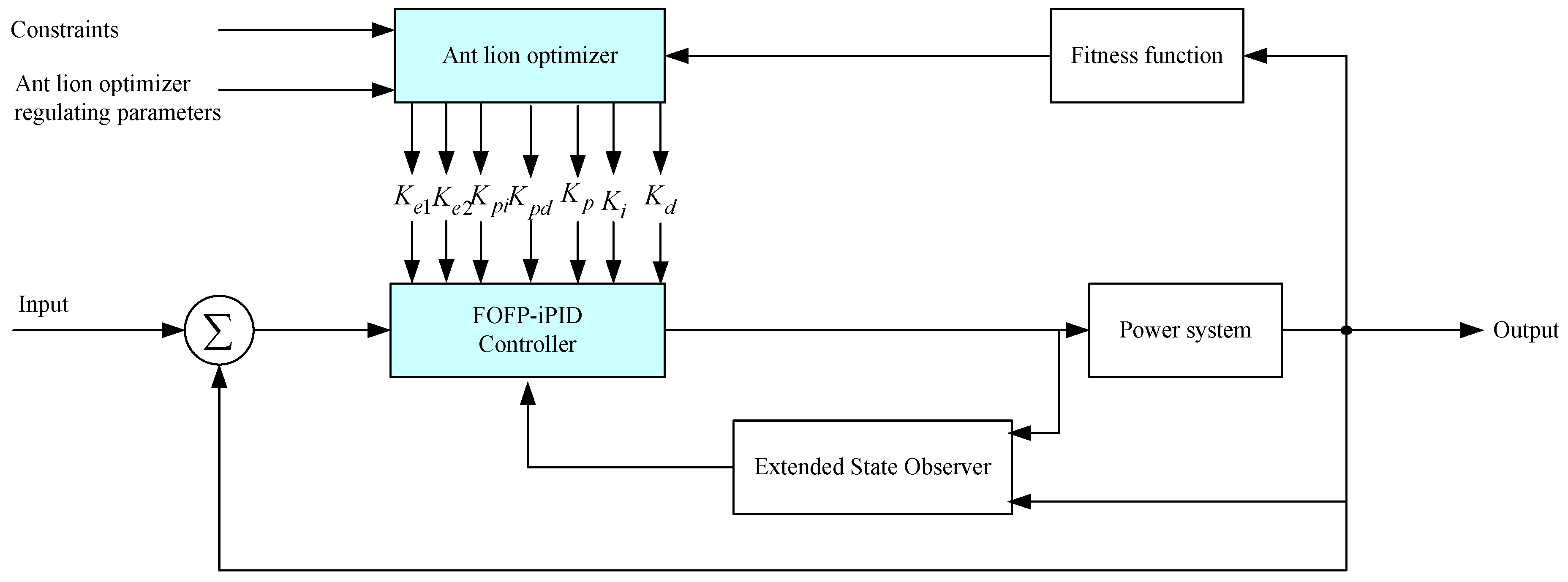
  • The SFs of the controllers are adjusted employing the ALO algorithm.
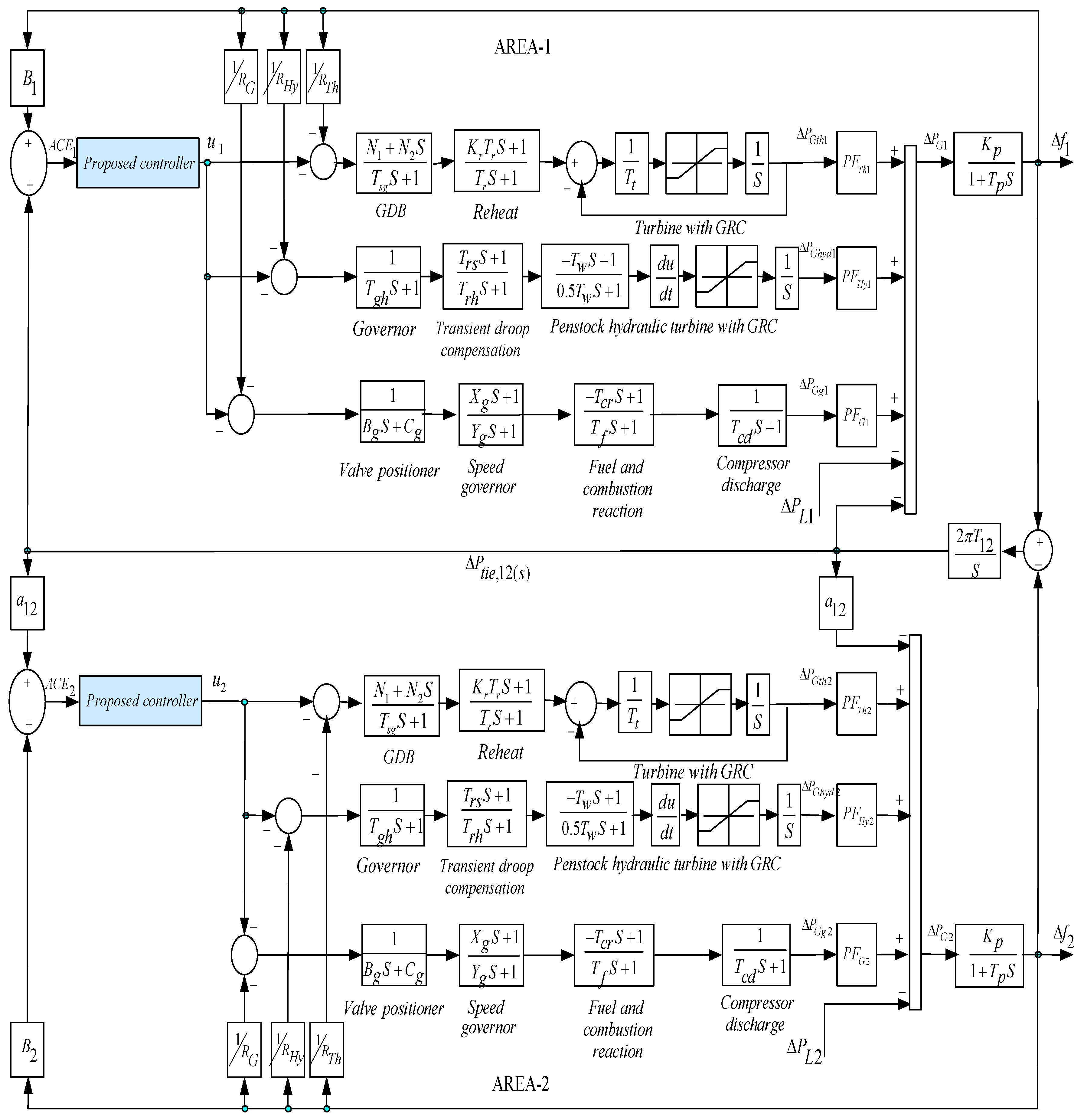
  • The proposed FOFP-iPID controller is evaluated on an interconnected two-area power system in which the physical constraints are taken into account for challenging realization.
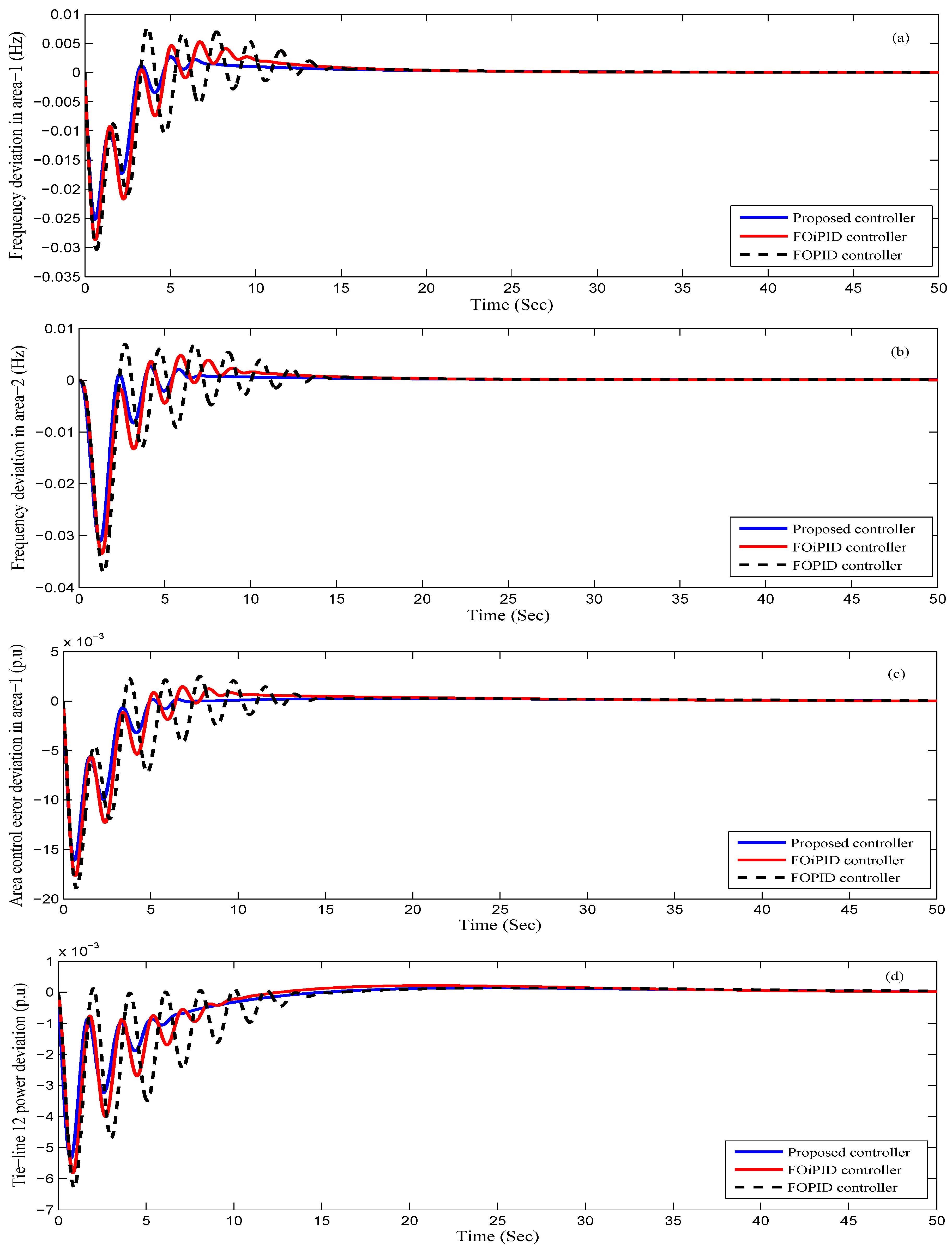
  • The performance of the suggested controller is evaluated by comparing the results with other controllers, such as FOiPD and FOPID controllers for the same plant [17].
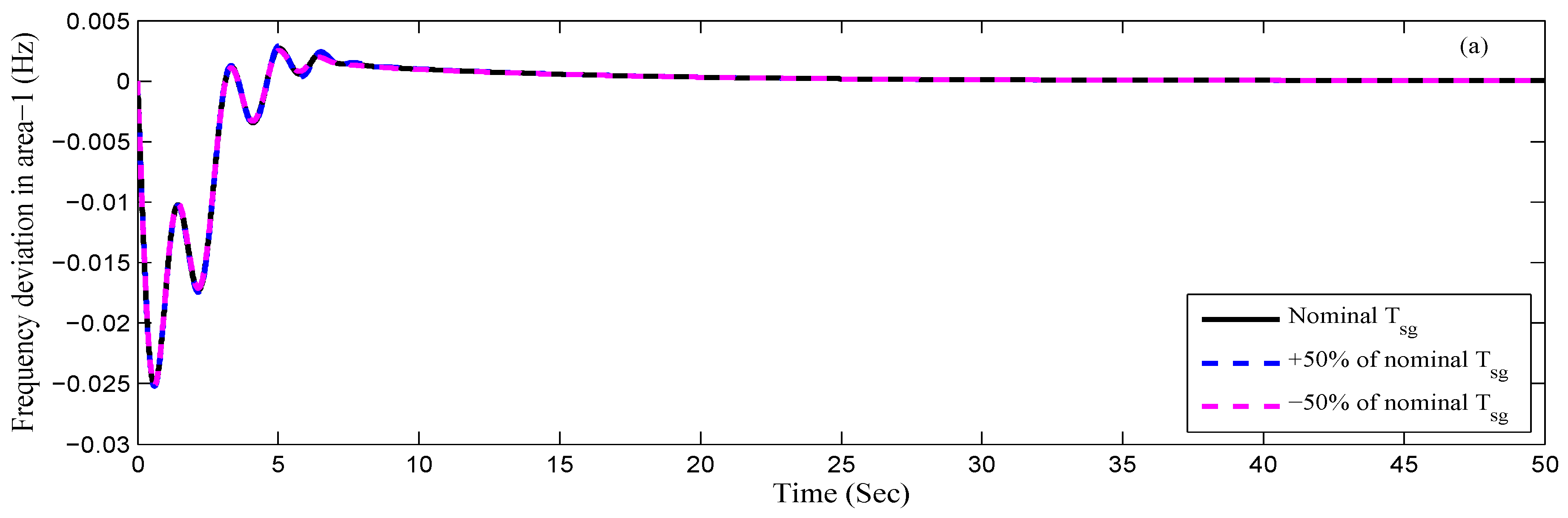
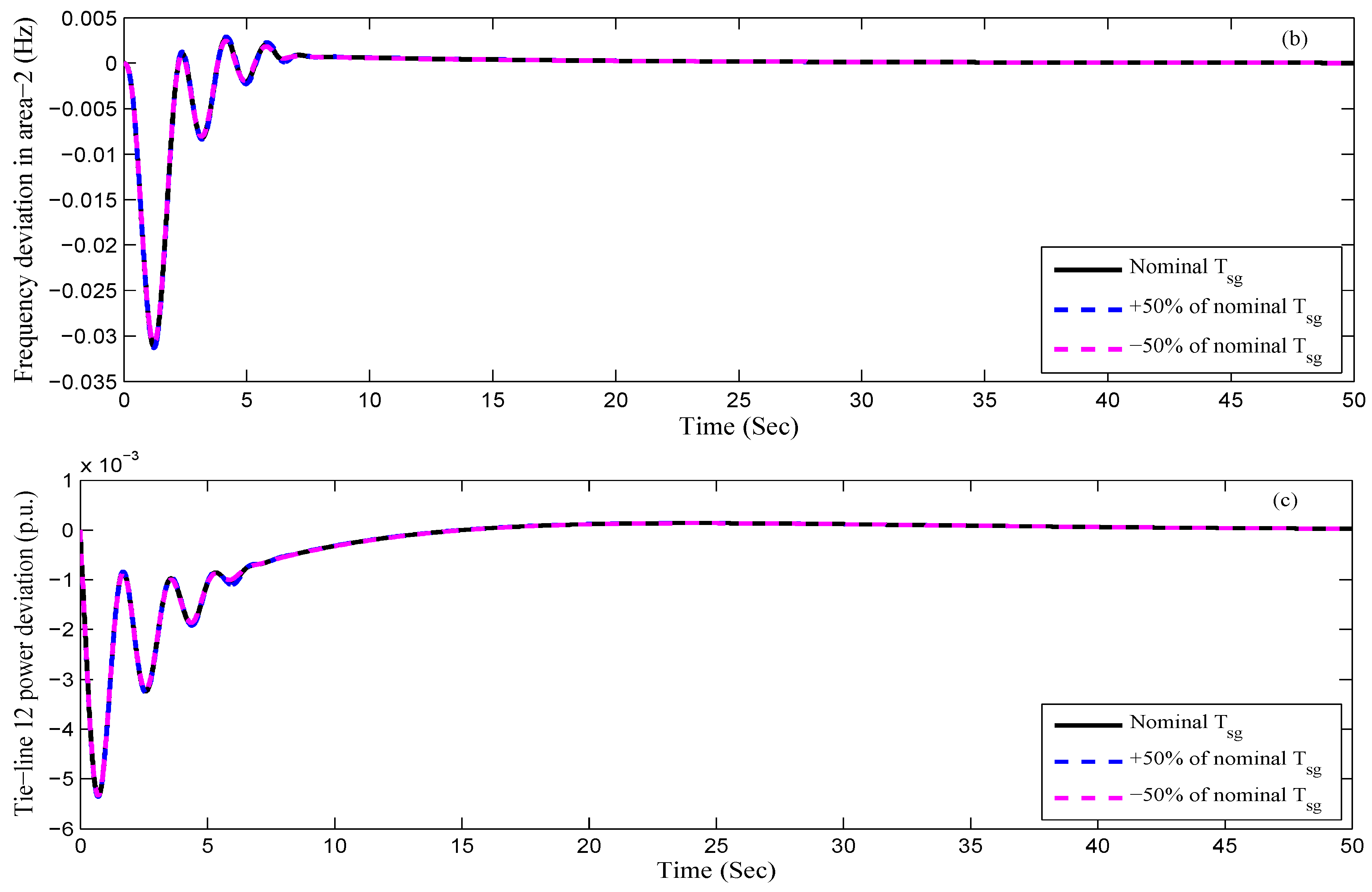
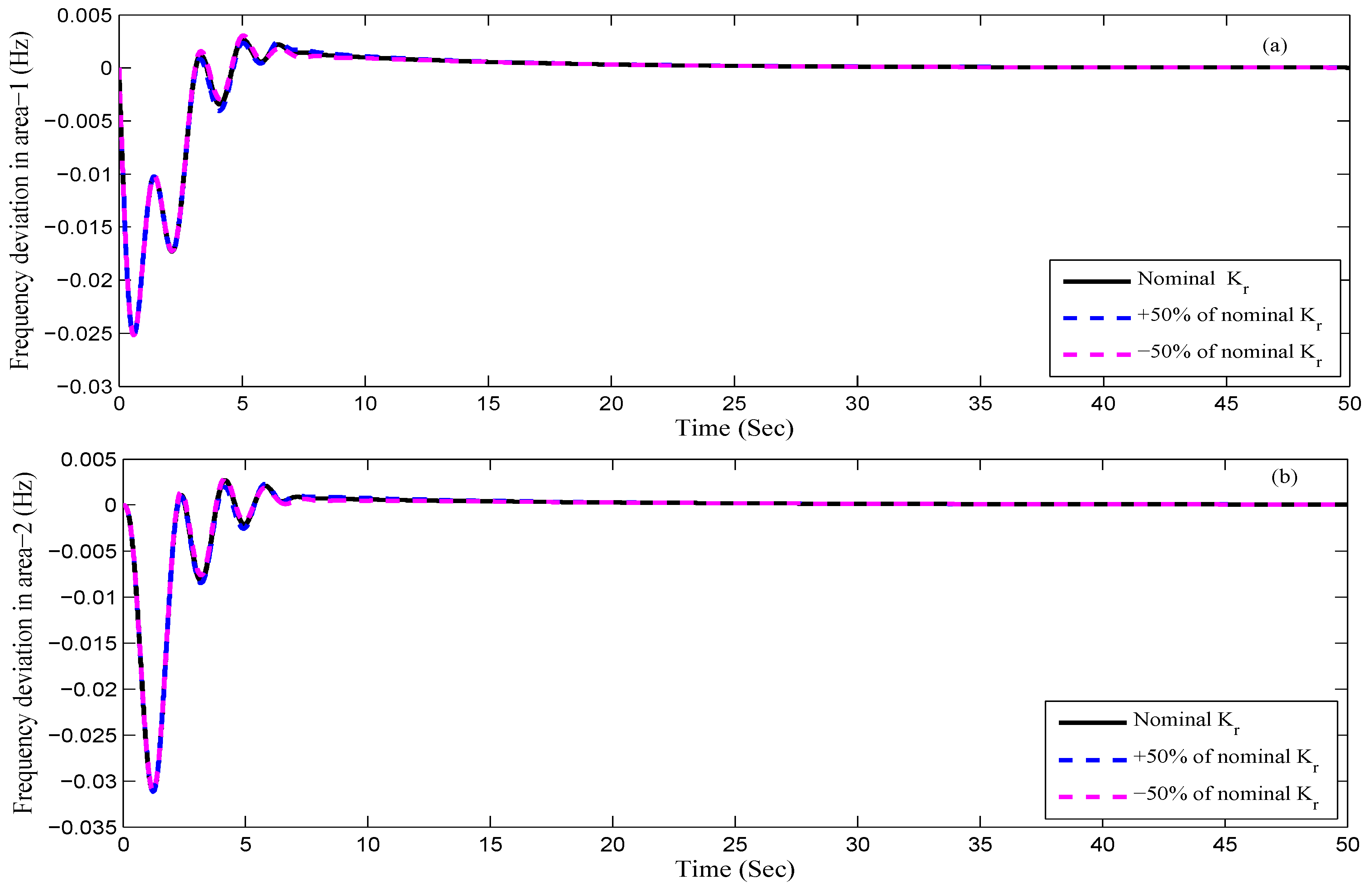
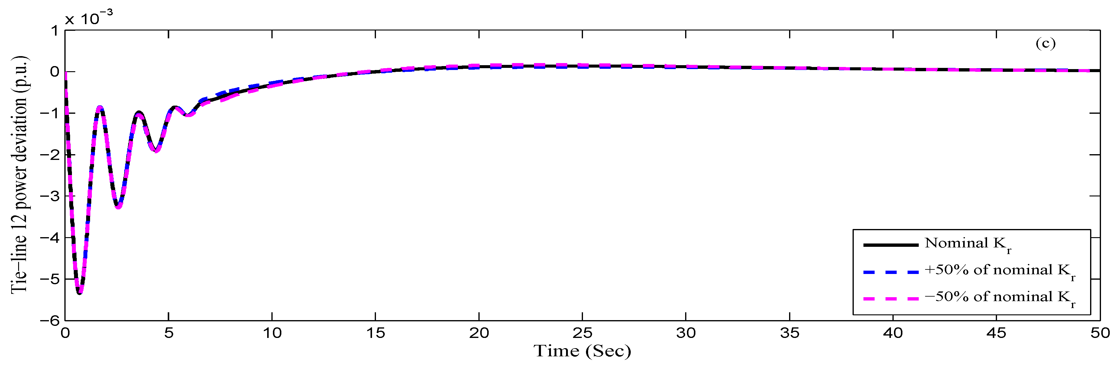
  • Sensitivity analysis is carried out to show the robustness of the FOFP-iPID controller under a wide range of parameter variations and LPs.
The rest of the sections of this article are organized as follows: The investigated power system is modeled in Section 2; Controller structure is elaborated in Section 3; the objective function and its optimization are stated in Section 4; simulation results are offered in Section 5; finally, the conclusion of the article is presented in Section 6.

2. Mathematical Modelling of Investigated Power System

In this article, an interconnected two-area power system, where every area comprising diverse generation-utilities—as highlighted in Figure 1—is studied. The parameters of the system are obtained from References [17,18,19] and are listed in Appendix A. The different parameters of the plant are furnished in Table 1 [18]. The GRC for the hydro and thermal utilities as well as the GDB for the thermal plants in both control areas are addressed in the system model. Referring to Reference [4], the Fourier coefficients of the governor dead band (GDB) are taken as N 1 = 0.8 and N 2 = 0.2 / π . A suitable GRC model of 10%/minute for the thermal utility of Figure 1 is applied to both raising and falling rates. On behalf of the hydro utility, a 270%/minute for raising and 360%/minute for falling generation unit of the GRC model is established [18]. Assume for area-1 the constant quantity of P F T h , P F H y and P F G are the shares of power generation (PGs) utilities from the sources mentioned above. As a result, under regular operating states, there is no mismatch between generation and load. Consequently, the power generated from the thermal, hydro and gas power utilities are given below:
P G 1 T h e r m a l = P F T h 1 P G 1
P G 1 H y d r o = P F H y 1 P G 1
P G 1 G a s = P F G 1 P G 1
Under nominal operating conditions, the aggregated power generated, P G 1 for area-1 is given by
P G 1 = P G 1 T h e r m a l + P G 1 H y d r o + P G 1 G a s
P G 1 = P F T h 1 P G 1 + P F H y 1 P G 1 + P F G 1 P G 1
and
P F T h 1 + P F H y d 1 + P F G 1 = 1
for small load change in area-1, Equation (4) can be modeled as:
Δ P G 1 = Δ P G 1 T h e r m a l + Δ P G 1 H y d r o + Δ P G 1 G a s
Similarly, Equations (1)–(7) can be modeled for area-2. From Figure 1, the input to the controller is their respective ACEs, and the output is the signal u i . Based on References [3,4], the area control errors (ACEs) of both areas can be formulated as:
A C E 1 = B 1 Δ f 1 + Δ P t i e 12
A C E 2 = B 2 Δ f 2 + Δ P t i e 21
where Δ P t i e 12 and Δ P t i e 21 are the perturbation in tie-line power interchange in area-1 and area-2, respectively. Δ f 1 and Δ f 2 are the frequency deviation in area-1 and area-2.

3. Controller Structure

The design structure of the suggested controller is described in this section. Initially, a briefly review of the fractional order is presented, followed by the design steps of the fractional order intelligent PID (iPID) controller, and then the proposed fractional order fuzzy pre-compensated intelligent PID (FOFP-iPID) controller is described.

3.1. Design of the Fopid Controller

Fractional order (FO) is a generalization of integer order integral and differential to the FO operator D t α a where a and t signify the limits of the operation and α is the FO which is a complex number. Thus, the FO operator can be stated as:
D t α a = d α / d t α , α > 0 1 , α = 0 a t d τ α , α < 0
There are different descriptions and approximations for FO derivative and integral [17]. The FO derivative based on the Riemann-Liouville (R-L) definition is stated by:
D t α a f ( t ) = 1 Γ ( n α ) d n d t n a t ( t τ ) n α 1 f ( τ ) d τ
where n 1 > α n . The FO integral based on R-L definition modeled by:
D t α a f ( t ) = 1 Γ ( α ) a t ( t τ ) α 1 f ( τ ) d τ
For simplicity, Laplace transformation (LT) is routinely employed to designate the fractional order. In general 0 < α < 1 , and the LT of the R-L fractional derivative or integral is modeled by:
L D t α a f ( t ) = s α F ( s ) k = 0 n 1 s k D t α k 1 a f ( t ) | t = 0
Under zero initial conditions for
L D t ± α a f ( t ) = s ± α F ( s )
This signifies that when zero initial concepts are concerned, the dynamic responses of a plant designated by FO differential equations turns to transfer functions with fractional orders of ‘s’ (Laplace operator) [20]. The best performance of the FOs relies on the order of the estimation ( N ¯ ). Minimum values of N ¯ may drive ripples in the phase behaviors. These waves can be handled by raising the values of N ¯ , but the computational load of the estimation becomes difficult and complex in the hardware implementation [21]. In this article, 5 t h order Oustaloup’s recursive estimation is considered while fitting frequency variety [ ω l , ω h ] is taken as [0.01, 100] r a d / s . The architecture of the FO designed in this study is performed with employed MATLAB/Simulink based toolboxes [22]. The purpose of the toolbox is to furnish a user-friendly, rapid and precise tool for simulating different FO controllers for several practices.
The FOPID controller is an aggregate of factors with additional degrees of freedom on behalf of the controller gains along with the integro-differential order of the operators, which has the following formula [13,17].
P I λ D μ = K p + K i s λ + K d s μ
where, K p , K i , K d are the gains of the controller, λ and μ the order of integration and differentiation, respectively [17].

3.2. Design of the Foipid Controller

The dynamics model for a general nonlinear system can be expressed as [4]:
y ( n ) = ε ( t ) + α ¯ · u i ( t )
where n 1 , α ¯ is the input gain, and ε ( t ) denotes the unknown disturbances. If n = 2 , and ε ( t ) , α ¯ are identified items, then the FOiPID technique can be suggested as in Equation (17).
u F O i P I D ( t ) = 1 α ¯ ε ^ ( t ) + y ¨ * + K p e i ( t ) + K i d λ e i ( t ) d t λ + K d d μ e i ( t ) d t μ
Therefore, the steady error of the plant can be attained by adjusting the factors K p , K i , K d and λ and μ . The estimated value of the ε ^ ( t ) can be obtained by employing the ESO approach [23]. The ESO has more advantages in a control system such as those used to estimate the internal and external uncertainties, which can be considered as:
e 1 = z 1 Δ f z ˙ 1 = z 2 β 1 f a l ( ν , ρ 1 , σ ) z ˙ 2 = z 3 β 2 f a l ( ν , ρ 2 , σ ) + b · u F O i P I D z ˙ 3 = β 3 f a l ( ν , ρ 3 , σ ) ε ^ ( t ) = z 3
where z 1 , z 2 and z 3 represent the state of ESO; β 1 , β 2 and β 3 represent the observer gains, e 1 is the observer error.
f a l ( ν , ρ , σ ) = ν ρ sign ( ν ) , ν > σ ν / σ 1 ρ , otherwise 0 ρ 1 , σ > 0

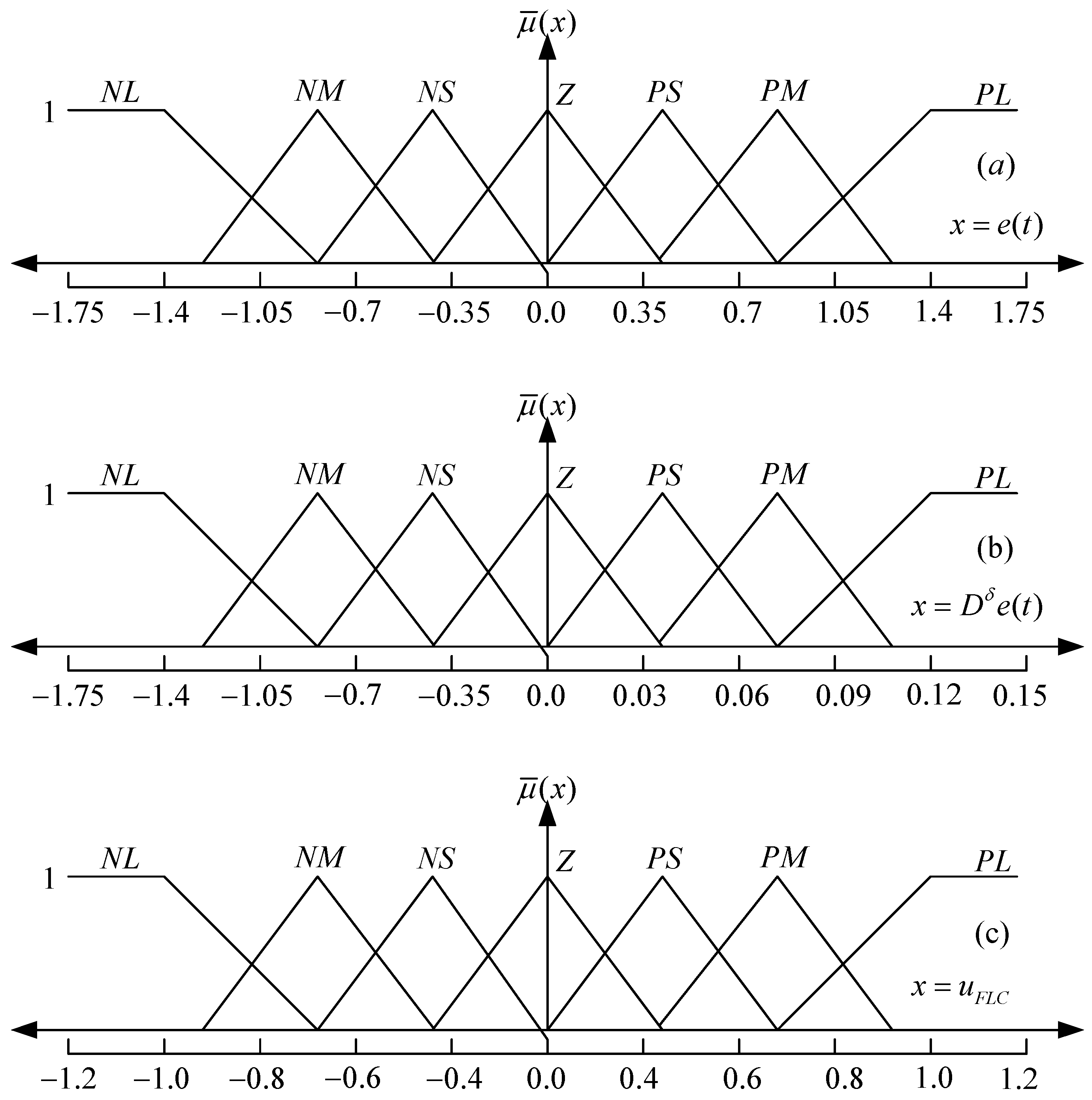
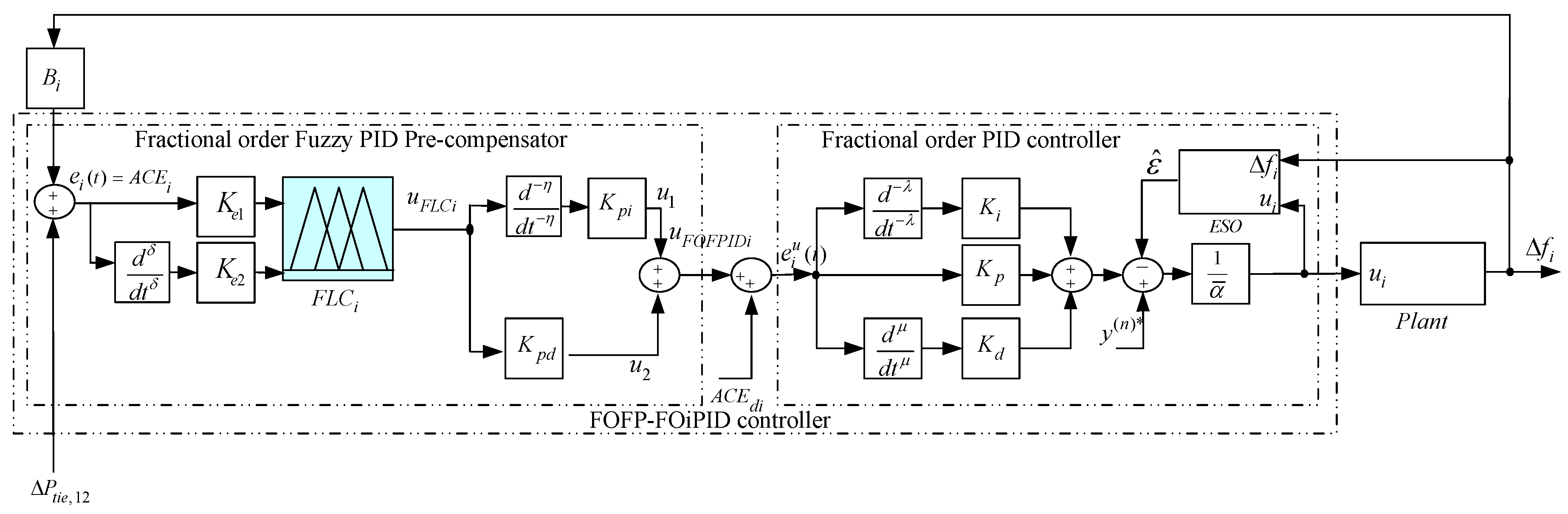
3.3. Design of the Fractional Order Fuzzy Pre-Compensated Intelligent PID (FOFP-iPID) Controller

A novel hybrid fractional order fuzzy pre-compensated intelligent PID (FOFP-iPID) controller is proposed in this study, where the suggested controller is synthesised from the fractional order fuzzy pre-compensator (FOFP) and the fractional order intelligent PID (FOiPID) controller. Firstly, the FOFP controller is subjected to modification of the control signal for compensating overshoots/undershoots in transient output response and also amended the dynamic performances in the presence of parameter variations and load perturbations. Then, the FOiPID controller is equipped to make the controller more robust, effective, and to ameliorate the dynamic performance. As a result, the suggested FOFP-iPID controller is comprised of unique features of the fuzzy pre-compensated controller with FO, which aimed to overcome the problem of LPs in the output response. The advantage of the suggested FOFP-iPID controller is simply in its architecture, high efficiency and is the first time it has been employed for LFC strategy. The proposed FOFP-iPID controller is highlighted in Figure 2. In Figure 2, the dynamics of the proposed hybrid fractional order fuzzy pre-compensated intelligent PID (FOFP-iPID) controller can be described by the following equations. From Figure 2 the area control error ( e i ( t ) = A C E i ) can be formulated as:
e i ( t ) = B i Δ f i + Δ P t i e i j
From Figure 2:
u 1 ( t ) = K p i d η u F L C i ( t ) d t η K e 1 e i ( t ) , K e 2 d δ e i ( t ) d t δ
u 2 ( t ) = K p d u F L C i K e 1 e i ( t ) , K e 2 d δ e i ( t ) d t δ
where, η and δ signify the order of integro-differentiator of the FOFP controller, K e 1 and K e 2 represent the input gains, and u F L C i is the fuzzy output signal.
Now, combining Equations (21) and (22) gets the controller signal ( u F O F P I D i ( t ) ), in which u F O F P I D i ( t ) represents the pre-compensated term of the proposed strategy.
u F O F P I D i ( t ) = K p i d η u F L C i ( t ) d t η K e 1 e i ( t ) , K e 2 d δ e i ( t ) d t δ + K p d u F L C i K e 1 e i ( t ) , K e 2 d δ e i ( t ) d t δ
Now, the new error e i u ( t ) which is incorporated into the fractional order intelligent (FOiPID) controller can be derived from Figure 2:
e i u ( t ) = u F O F P I D i ( t ) + A C E d i
where, A C E d i denotes the desired error of A C E i . Finally, the controller signal ( u i ( t ) ) of the proposed FOFP-iPID controller can be derived directly from Figure 2 by using the fractional order intelligent PID controller concept:
u i ( t ) = 1 α ¯ ε ^ ( t ) + y ( n ) * + K p e i u ( t ) + K i d λ e i u ( t ) d t λ + K d d μ e i u ( t ) d t μ
As shown in Figure 2, the terms K e 1 , K e 2 , K p i and K p d are the scaling factors (SFs) for the fractional order fuzzy logic pre-compensated (FOFP) controller. Furthermore, λ , μ , η and δ represent the extra fractional order parameters, which can be used in the control system that will increase the flexibility of regulating the parameters. In doing so, the associated gains and the scaling factors (SFs) are optimized by employing the ALO algorithm.
The implementation phases of the FLC inference are mainly comprised of the fuzzy rule base, membership functions, fuzzification and defuzzification processes. The error ( e ( t ) ) and its fractional derivative ( D δ e ( t ) ) are selected as input variables and u F L C is selected as the output variable of the FOFP controller, as depicted in Figure 2. These variables are fuzzified into 7 triangular membership functions, which are characterized by linguistic variables, as shown in Figure 3, and then the rule base associated with the fuzzy controller is furnished in Table 2, which consists of 49 rules. The control rules are constructed from the following rule: For instance, see the fifth row and the seventh column in Table 2: If A C E is PS and A C ˙ E is PL, then u F L C is LN.

4. Objective Function and Its Solution

4.1. Objective Function for Controller Design
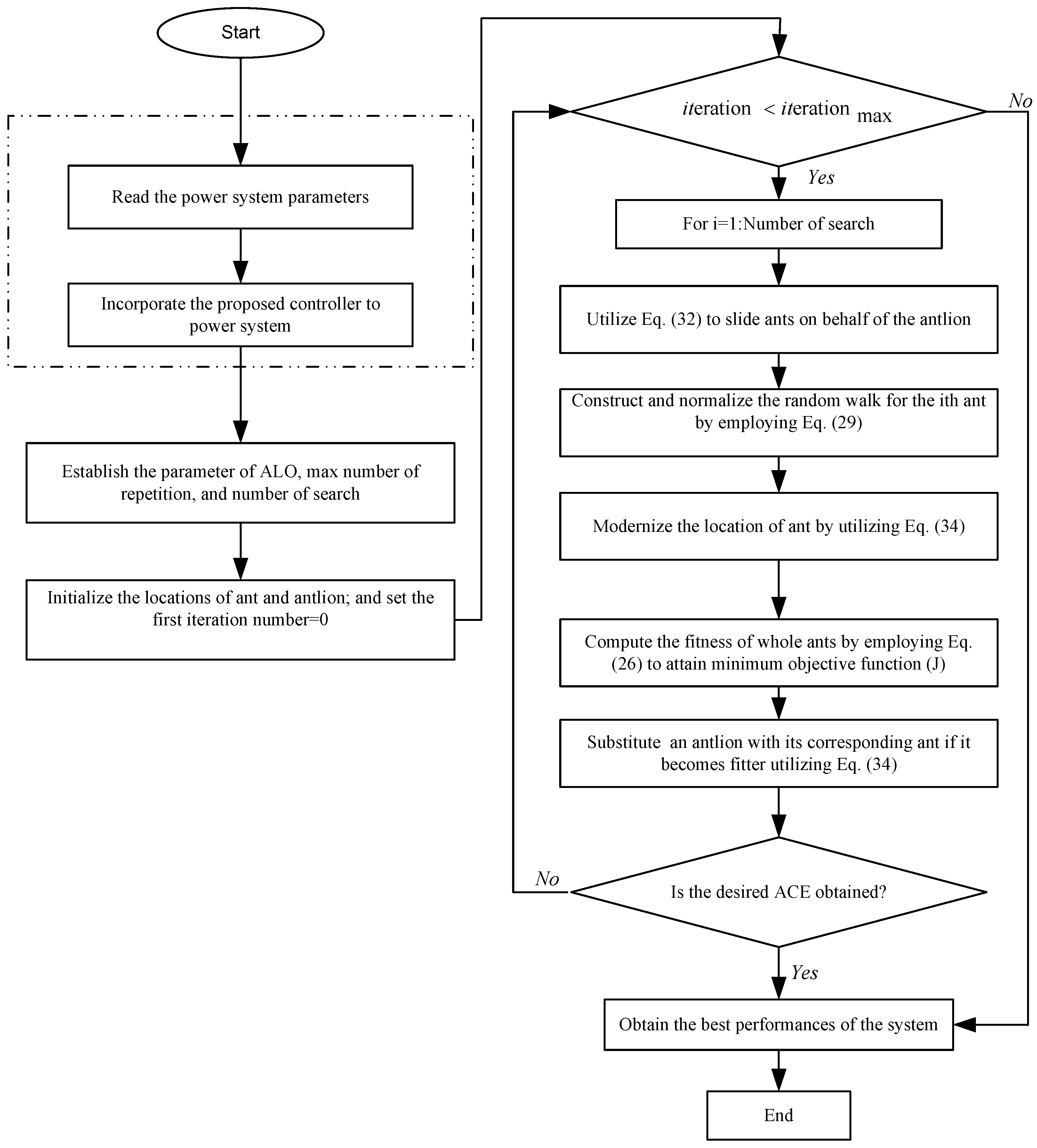
In order to restore the essential frequency in control-areas, a suitable objective function is significant for the optimization technique to explore the controller parameters [4]. In this article, ITAE is deemed as an objective function ( J ) to regulate the controller’s gains.
J = I T A E = 0 T s i m t · Δ F 1 + Δ F 2 + Δ P t i e , 12 · d t
An optimization problem is carried out by using the ALO technique as in Reference [24] to attain the optimal SFs incorporated into the following constraints: K p min K p K p max , K i min K i K i max , K d min K d K d max , K e 1 min K e 1 K e 1 max , K e 2 min K e 2 K e 2 max , K p i min K p i K p i max , K p d min K p d K p d max , λ min λ λ max , μ min μ μ max , η min η η max , δ min δ δ max . The proposed topology of the designed FOFP-iPID controller based on ant lion optimizer (ALO) is highlighted in Figure 4.

4.2. ALO Algorithm

For the first time, the ALO algorithm is used to regulate the parameters of FOFP-iPID controller in the LFC of the interconnected multi-area multi-source power system. The ALO algorithm is a new optimization technique which was recently suggested and added to the meta-heuristics category for handling the constrained optimization problems which was first addressed by Seyedali Mirjalili in Reference [24]. It is a global optimizer method, which achieves good equilibrium between exploration and exploitation capability and gives a high probability of avoiding inactivity into local optima and hence; guarantees the convergence. Another merit of the ALO, it does not have any internal scaling parameters to regulate.
The ALO technique imitates the hunting interaction behavior of a predator (ant lions). In order to model the interactions aforesaid, ants are demanded to move over the search space, and ant lions are permitted to hunt them and become fitter by employing traps. Since ants (prey) move randomly in nature like other insects when seeking the food, the stochastic walk is selected for modeling the ants’ (prey) activities as follows:
W ( t ) = [ 0 , c u m s u ( 2 r ( t 1 ) 1 , c u m s u ( 2 r ( t 2 ) 1 ) , · · · , c u m s u ( 2 r ( t n ) 1 ) ]
where W ( t ) signifies the random walks of ants, c u m s u mean calculate the cumulative sum, n denotes the maximum iterations, and r ( t ) represent the stochastic function which can be defined as:
r ( t ) = 1 i f rand > 0.5 0 i f rand 0.5
where r a n d signifies the randomly generated number, which uniformly dispersed in the range of [ 0 , 1 ] . The following steps describe the main stages in the hunting technique of ant lions.

4.2.1. Random Walk of Ants

In each phase of the optimization, the ants appraise their locations σ ¯ to υ according to Equation (27), to guarantee that all the locations of the ants are inside the confine of the search space, they are normalized by employing the following modeling:
W i t = W i t υ i × d i t I i t σ ¯ i υ i + I i t
where υ i , σ ¯ i represent the minimum and supreme of the stochastic walk. I i t , d i t signify the minimum and supreme of the variables, respectively.

4.2.2. Trapping in Antlions Traps

The following equations describe the influence of the ant lions’ traps on the stochastic walks of the ants:
I i t = A n t l i o n j t + I t
d i t = A n t l i o n j t + d t

4.2.3. Building Traps

Throughout optimization, the ALO utilizes the roulette wheel option operator, to select ant lions based on their fitness. This strategy provides more opportunity for the ant lions to hunt prey.

4.2.4. Sliding Ants against toward Antlion

Regarding the aforesaid techniques, ant lions are capable of creating traps proportional to their fitness and the ants move close to the center of the hole. After the ant lions catch an ant in a trap, they will shoot the sand outwardly from the middle of the trap [24]. This technique is mathematically identified as follows, where H is the ratio.
I t = I t H
d t = d t H

4.2.5. Catching Preys and Rebuilding the Traps

The final phase of the process (hunt) occurs when an ant arrives at the bottom of the trap and is grasped in the ant lion’s jaw. To catch the ants with a predator and re-constructing the trap in order to catch new prey can be proposed with the following:
A n t l i o n j t = A n t i t , i f f ( A n t i t ) > f ( A n t l i o n j t )
where, A n t l i o n j t signifies the i t h position of the picked antlion at iteration t and A n t i t is the location of the designated ant at iteration t.

4.2.6. Flowchart of the ALO Algorithm

The ALO algorithm is employed in this article to explore the SFs of the proposed FOFP-iPID controller, which is implemented for an interconnected multi-area multi-source to enhance their dynamic performances. The main stages of the ALO are briefly furnished in the Flowchart as highlighted in Figure 5.

5. Simulation Results and Discussion

This section demonstrates the efficacy and capability of the proposed FOFP-iPID controller for solving the LFC-based interconnected power system. The proposed FOFP-iPID controller is designed separately for each control area using the ALO algorithm. The dynamic performance of the FOFP-iPID controller is assessed by comparing the performances with a recently published article based on the FOPID controller for an identical system [17]. The simulation procedures are outlined as:
(1)
Performance evaluation under different perturbations (LPs):
  • Performance evaluation of the suggested FOFP-iPID controller under step load perturbation (SLP) in area-1.
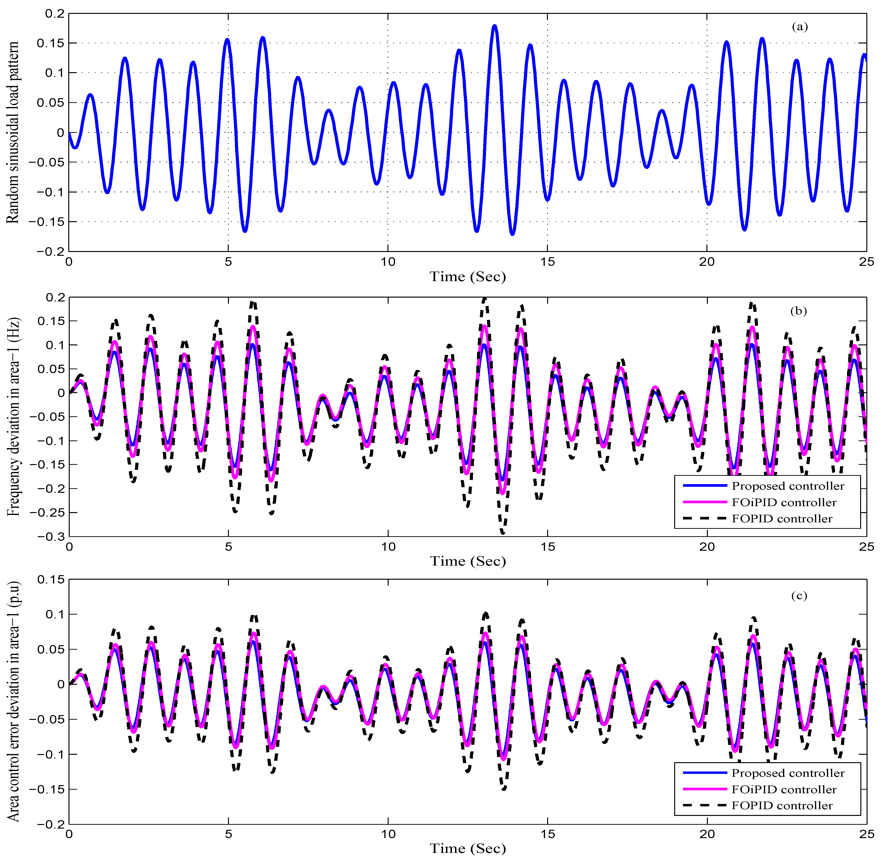
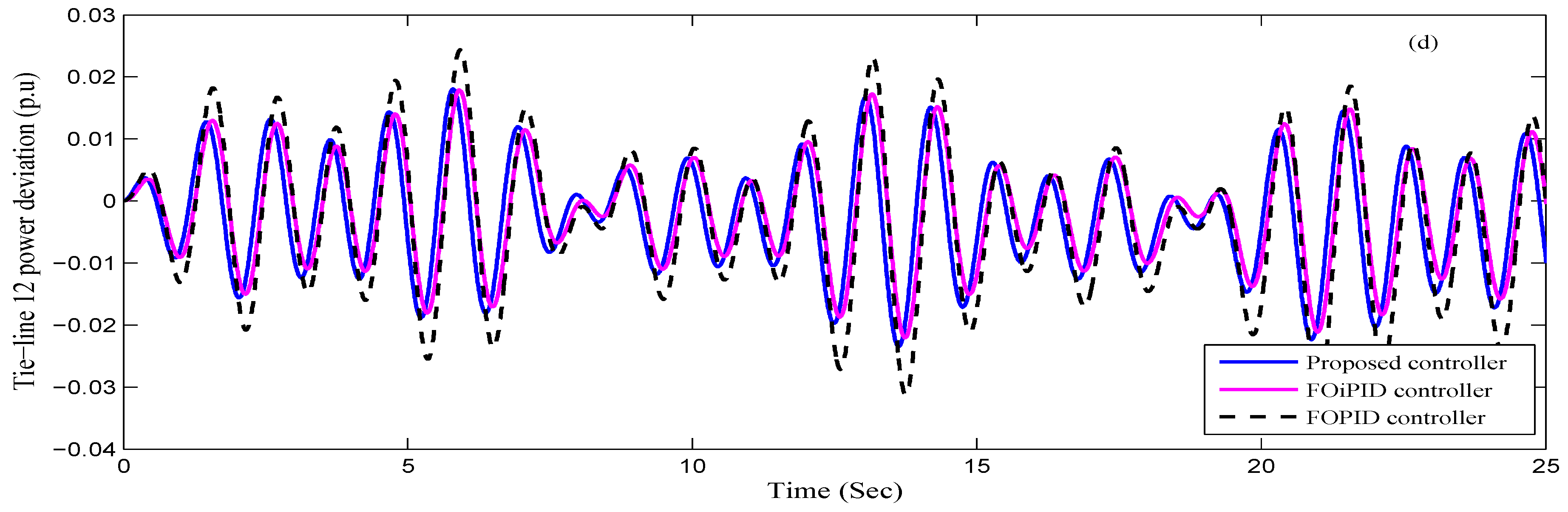
  • Performance evaluation of the suggested FOFP-iPID controller under sinusoidal load change (SLC) in area-1.
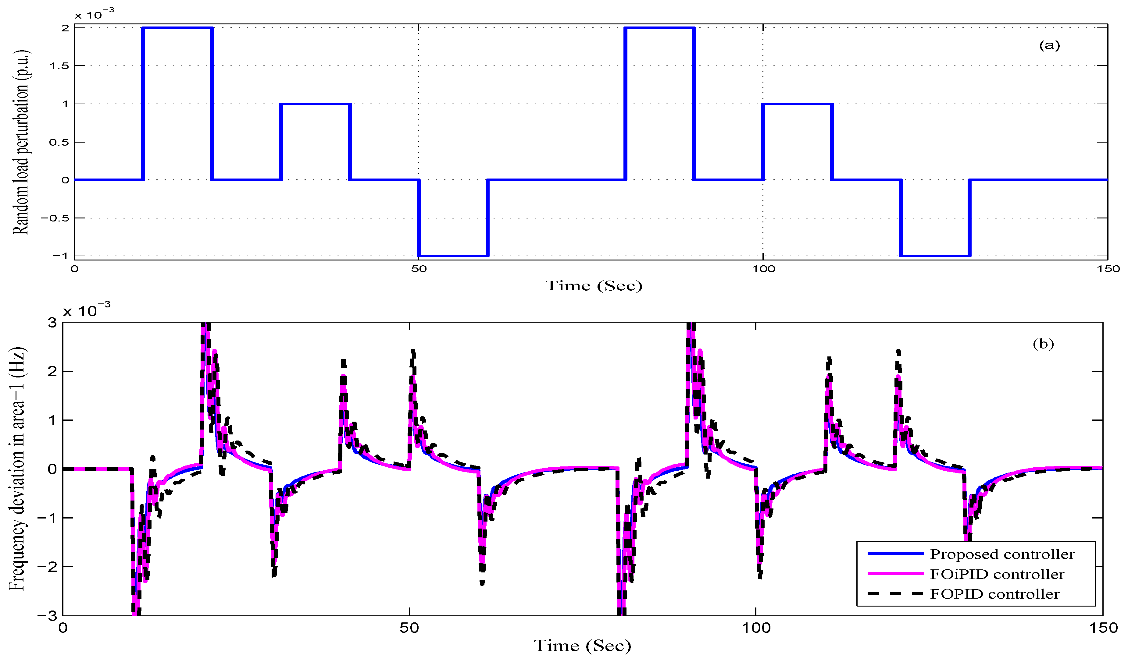
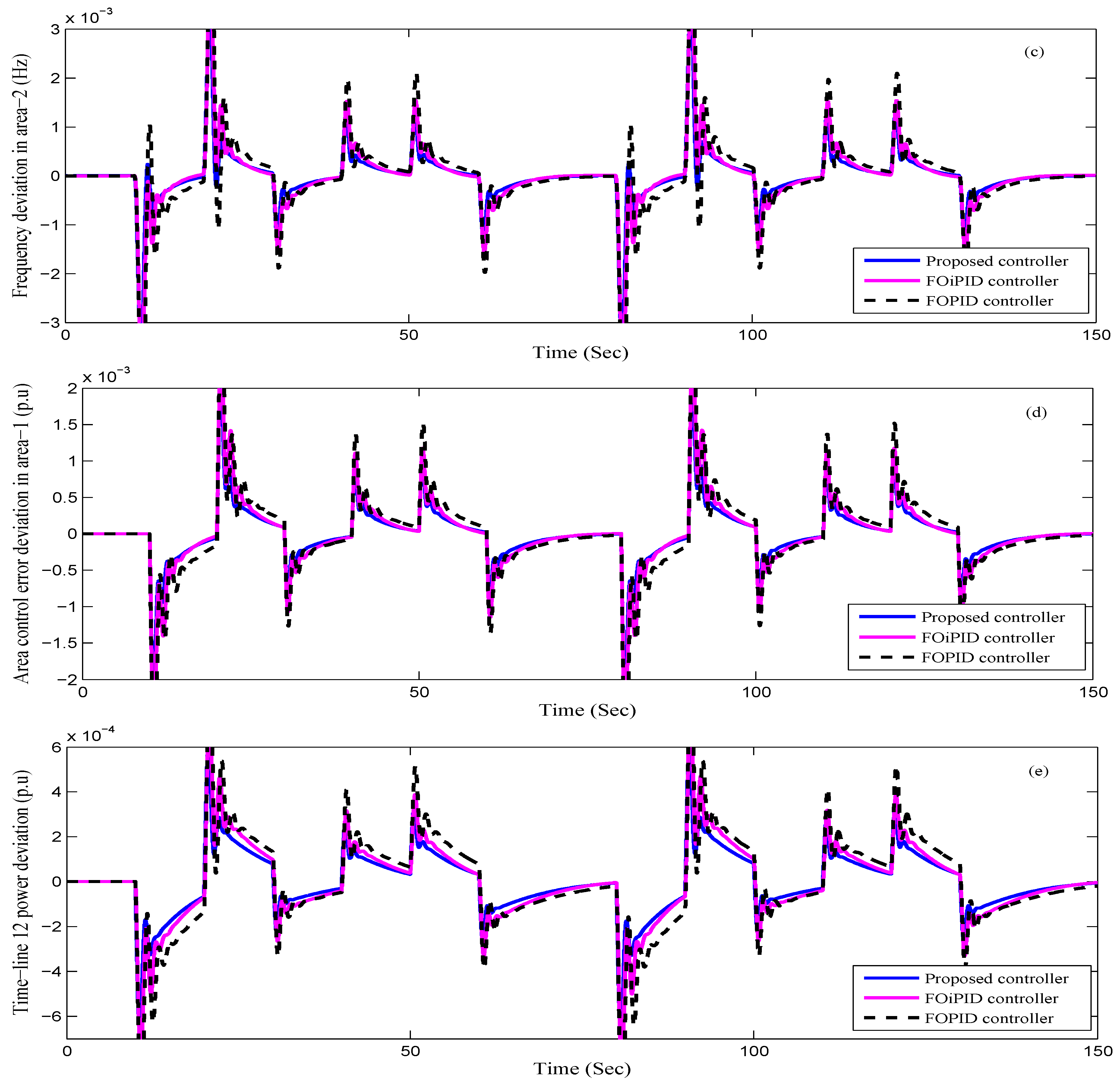
  • Performance evaluation of the suggested FOFP-iPID controller under random load perturbation (RLP) in area-1.
(2)
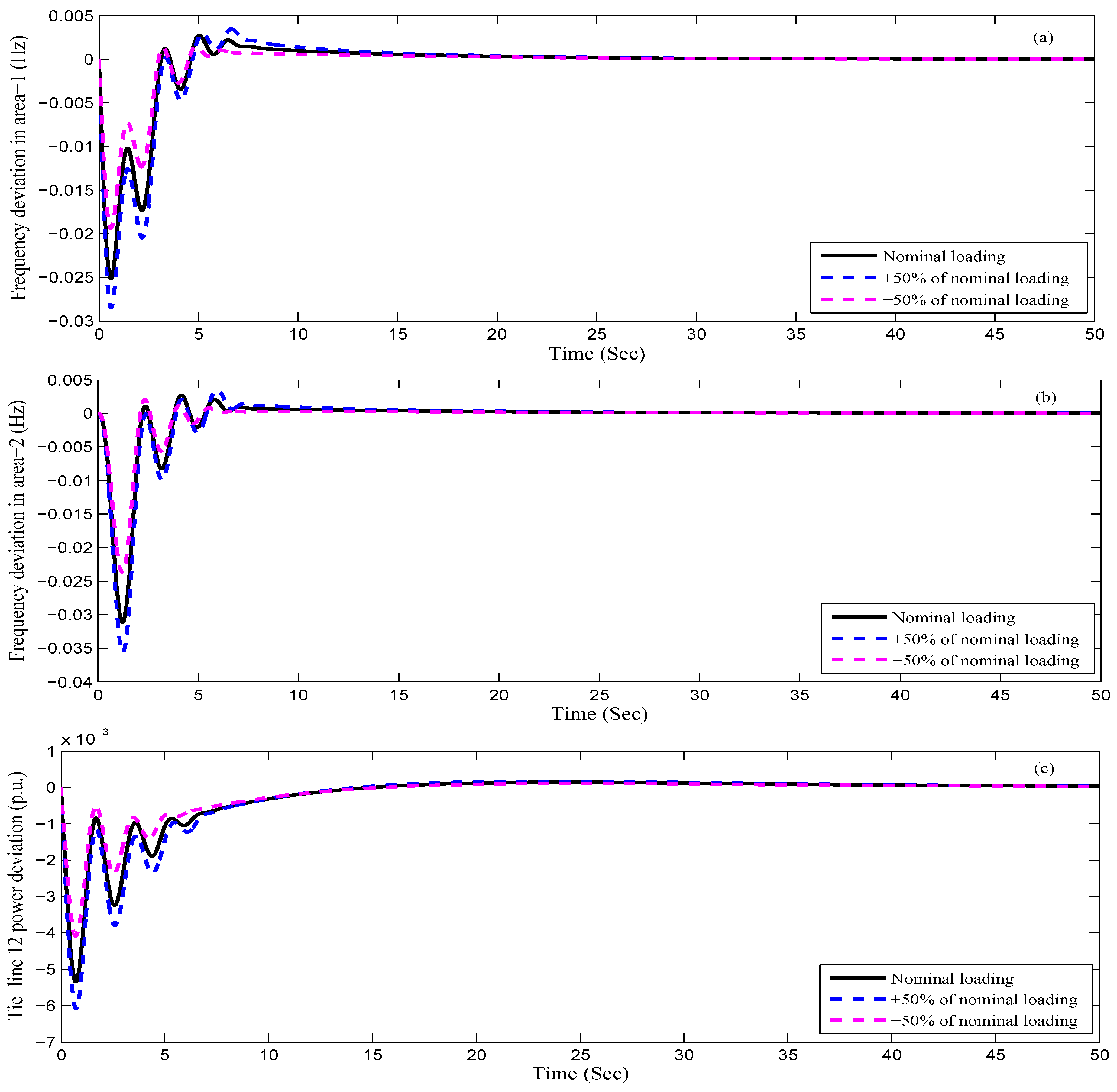
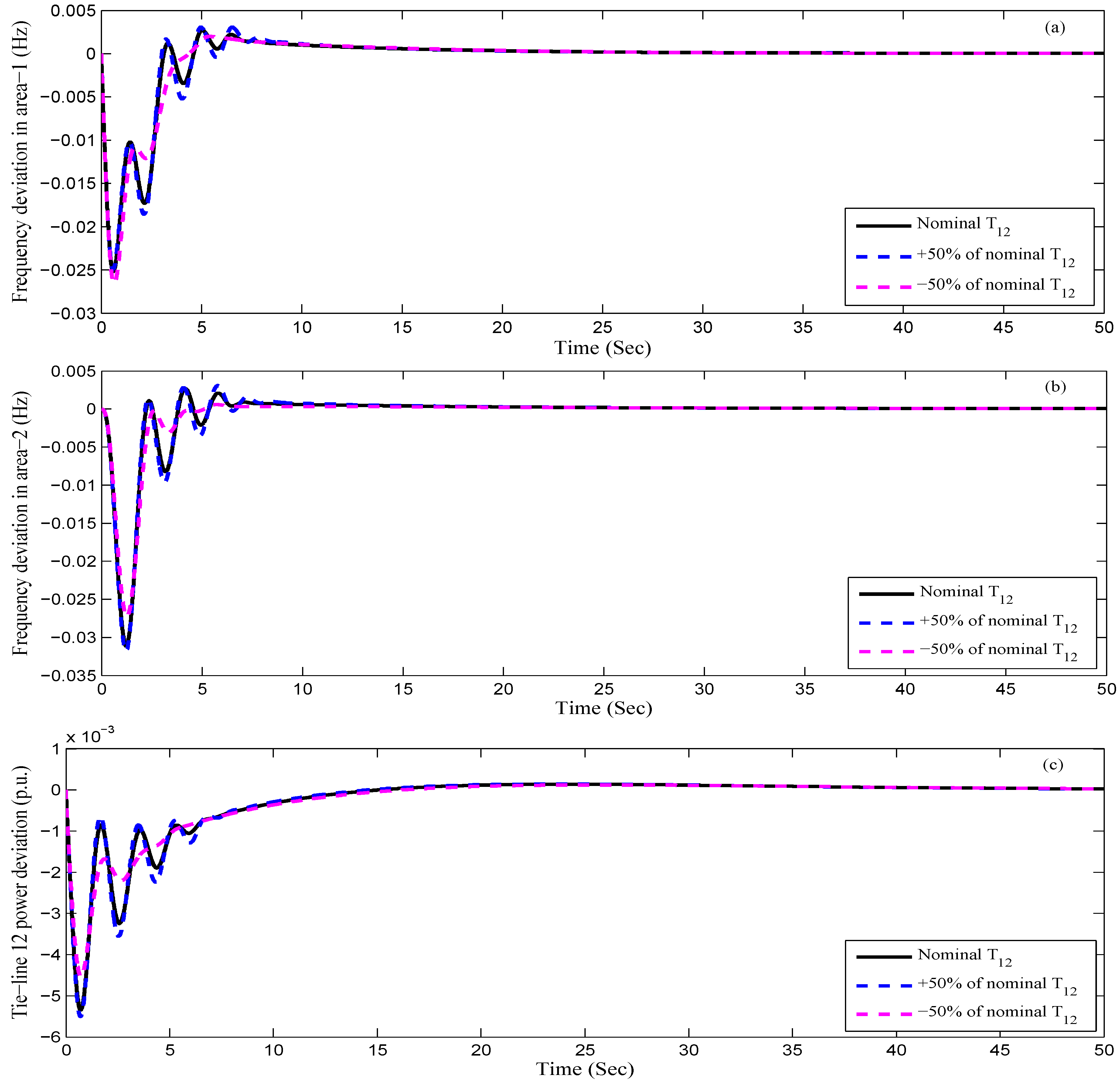
Sensitivity analysis is also carried out to appraise the robustness of the current controller against ± 50 % uncertainty in system parameters.

5.1. Performance Evaluation under SLP

In this scenario, the two-area interconnected power system, as shown in Figure 1, is incorporated with the FOFP-iPID controller in each area as a secondary controller, individually. Then, the 1% step load perturbation is subjected to area-1 to investigate the performance of the concerned power plant. The controller’s gains are attained by the ALO algorithm and are provided in Table 3. The performance of the designed controller is compared with the other controller’s techniques, such as the FOPID and FOiPID controllers, for an identical power plant, and the comparative performances are tabulated in Table 4. It is clearly inspected from Table 4 that the minimum ITAE value is obtained with FOFP-iPID controller (ITAE = 0.7057) compared to the FOiPID controller (ITAE = 0.9714) and the FOPID controller (ITAE = 1.178). It is clear from the above discussion that the FOFP-iPID controller gives a better performance compared to FOPID and FOiPID controllers. The dynamic responses of the plant like area frequencies, tie-line power exchange and area control error (ACE) deviations corresponding to best gains of each controller are attained and displayed in Figure 6a–d. The settling time, peak overshoots/undershoots and ITAE are remarked on and depicted in Table 4. It is clear from the Figure 6a–d and Table 4 that the hybrid coordinated FOFP-iPID controller gives a better performance compared to the FOPID and FOiPID controllers from the point of view of settling time, the magnitude of peak overshoots/undershoots deviations and the ITAE value index.

5.2. Performance Evaluation of the Controller for Sinusoidal Load Changes

In order to evaluate the efficiency of the proposed controller under continuous load pattern, a sinusoidal load change (SLC) is applied to area-1 [10]:
Δ P L = 0.03 sin ( 4.36 t ) + 0.05 sin ( 5.3 t ) 0.1 sin ( 6 t )
Figure 7a–d shows the concerned SLC and the corresponding dynamical responses. The simulations reveal that the area frequency and tie-line power oscillations are restricted most effectively using the FOFP-iPID controller. As shown in Figure 7b–d, in comparison to the preceding perturbation patterns, only the amplitude of oscillations is confined, which shows that the oscillations are not mitigated entirely, due to the nature of the sinusoidal waveform. Thus, the FOFP-iPID controller provides a supreme stabilizing performance to the oscillations in comparison with the others.

5.3. Performance Evaluation of the Controller under Random Load Perturbations

Further, to check the supremacy of the proposed FOFP-iPID controller, a random load perturbation (RLP) as depicted in Figure 8a [4], is subjected to area-1. As seen, the steps vary both in amplitude and duration with the nature of load changes in a realistic power plant. The dynamic performances of the interconnected multi-source power system under the RLP are posted in Figure 8b–e. It is observed from Figure 8b–e that the suggested FOFP-iPID controller provides significant reduction even in the presence of RLP patterns.

5.4. Sensitivity Analysis

Sensitivity analysis is performed for the proposed controller under a wide change in system parameters [4,10]. Sensitivity is defined as the ability of the plant to work effectively while its variables are perturbed within a certain acceptable range [10,25]. In this study, the operating load conditions, T s g , K r and T 12 , are changed in the range of 50 % to + 50 % from their nominal values, individually. The quantitative analysis of the suggested FOFP-iPID controller in terms of ITAE, settling times, peak overshoots/undershoots with these changed conditions are furnished in Table 5 for 0.01 p.u SLP in area-1. It can be noticed from Table 5 that by enforcing ± 50 % with the uncertainties mentioned above, the values of the ITAE, settling times, maximum overshoots and minimum overshoots of the fluctuations swerve from their prescribed values slightly. However, it can be observed that by enforcing the ± 50 % extreme changes, the power plant is still dynamically stable since the damping measures are close to the prescribed values. For a better insight into the performance, the area frequencies and transmission-line power deviations are displayed in Figure 9, Figure 10, Figure 11 and Figure 12. It can be concluded from these discussions that in the case of utilizing FOFP-iPID controller the large and imposing uncertainties ( ± 50 % ) have a negligible impact on the plant performance. Briefly, the sensitivity analyses demonstrated that the system equipped with the FOFP-iPID controller is meaningfully robust to the concerned variations. As a result, when adjusting the scaling factors (SFs) of the suggested FOFP-iPID controller that is optimized for the specified condition, there is no need to re-adjust for the ± 50 % perturbation in parameter variations.

6. Conclusions

In this article, a novel hybrid fractional order fuzzy pre-compensated intelligent PID (FOFP-iPID) controller has been proposed for load frequency stabilization of a multi-area power system to improve system performance. The controller’s gains are regulated by the Anti lion optimizer (ALO) technique. This approach is based on ESO, which estimates the unknown uncertainties and is then added to the controller as feedback. The physical constraints of the GRC nonlinearity and GDB impact are also built into the system for a challenging investigation. The dynamic performance of the suggested FOFP-iPID controller is compared with the FOPID and FOiPID controllers under different load perturbations such as SLP, SLC and RLC patterns. The simulations showed that the suggested FOFP-iPID controller provides better dynamic performance in comparison with the other controllers in terms of less settling time, minimum peak overshoots/undershoot of the system performance. Furthermore, a sensitivity analysis is carried out and shows that the power plant subjected to the proposed FOFP-iPID controller is meaningfully robust to the considered large uncertainties in synchronizing coefficient, governor time constant of thermal plants, steam turbine reheat constant and loading conditions.

Author Contributions

All authors contributed to this work. A.H.G.H. and Y.-Y.L. performed the research, discussed the results, and prepared the manuscript. A.H.G.H. and Y.-Y.L. suggested the idea, and contributed to writing and revising the paper. All authors revised and approved the manuscript.

Funding

This work was supported by the National Natural Science Foundation of China under grants (No. 61871221, 61273076) and Chinese governmental scholarship (CSC No. 2015GXZT30).

Conflicts of Interest

The authors declare no conflict of interest.

Appendix A. System Parameters

P r t = 2000 MW (Rated capacity of each area), T w = 1.1 s, f = 60 Hz, T r s = 4.9 s, K p = 68.955 Hz/p.u.MW, T r h = 28.749 s, T p = 11.49 s, T g h = 0.2 s, T s g = 0.06 s, X g = 0.6 s, T t = 0.3 s, Y g = 1.1 s, R T h = 2.4 Hz/p.u.MW, R H y = 2.4 Hz/p.u.MW, R G = 2.4 Hz/p.u.MW, B 1 = 0.4312, B 2 = 0.4312, T f = 0.239 s, C g = 1, B g = 0.049 s, T 12 = 0.0433, P F T h = 0.5747, P F H y = 0.2873, P F G = 0.1380, a 12 = −1, T c r = 0.01 s, T r = 10.2 s, K r = 0.3, T c d = 0.2 s.

References

  1. Kundur, P.; Balu, N.J.; Lauby, M.G. Power System Stability and Control; McGraw-Hill: New York, NY, USA, 1994; Volume 7. [Google Scholar]
  2. Shankar, R.; Pradhan, S.R.; Chatterjee, K.; Mandal, R. A comprehensive state of the art literature survey on LFC mechanism for power system. Renew. Sustain. Energy Rev. 2017, 76, 1185–1207. [Google Scholar] [CrossRef]
  3. Cohn, N. Control of Generation and Power Flow on Interconnected Systems, 2nd ed.; Wiley: Hoboken, NJ, USA, 1971. [Google Scholar]
  4. Gomaa Haroun, A.H.; Li, Y.-Y. A novel optimized hybrid fuzzy logic intelligent PID controller for an interconnected multi-area power system with physical constraints and boiler dynamics. ISA Trans. 2017, 71, 364–379. [Google Scholar] [CrossRef] [PubMed]
  5. Shahalami, S.H.; Farsi, D. Analysis of Load Frequency Control in a restructured multi-area power system with the Kalman filter and the LQR controller. AEU Int. J. Electron. Commun. 2018, 86, 25–46. [Google Scholar] [CrossRef]
  6. Ahmadi, A.; Aldeen, M. An LMI approach to the design of robust delay-dependent overlapping load frequency control of uncertain power systems. Int. J. Electr. Power Energy Syst. 2016, 81, 48–63. [Google Scholar] [CrossRef]
  7. Liao, K.; Xu, Y. A Robust Load Frequency Control Scheme for Power Systems Based on Second-Order Sliding Mode and Extended Disturbance Observer. IEEE Trans. Ind. Inform. 2018, 14, 3076–3086. [Google Scholar] [CrossRef]
  8. Popli, N.; Ilic, M.D. Storage devices for automated frequency regulation and stabilization. In Proceedings of the 2014 IEEE PES General Meeting/Conference & Exposition, National Harbor, MD, USA, 27–31 July 2014. [Google Scholar]
  9. Chakraborty, T.; Watson, D.; Rodgers, M. Automatic Generation Control Using an Energy Storage System in a Wind Park. IEEE Trans. Power Syst. 2018, 33, 198–205. [Google Scholar] [CrossRef]
  10. Pradhan, P.C.; Sahu, R.K.; Panda, S. Firefly algorithm optimized fuzzy PID controller for AGC of multi-area multi-source power systems with UPFC and SMES. Eng. Sci. Technol. Int. J. 2016, 19, 338–354. [Google Scholar] [CrossRef]
  11. Sahu, R.K.; Panda, S.; Padhan, S. A hybrid firefly algorithm and pattern search technique for automatic generation control of multi area power systems. Int. J. Electr. Power Energy Syst. 2015, 64, 9–23. [Google Scholar] [CrossRef]
  12. Kim, J.-H.; Kim, K.-C.; Chong, E.K. Fuzzy precompensated PID controllers. IEEE Trans. Control. Syst. Technol. 1994, 2, 406–411. [Google Scholar]
  13. Morsali, J.; Zare, K.; Hagh, M.T. Applying fractional order PID to design TCSC-based damping controller in coordination with automatic generation control of interconnected multi-source power system. Eng. Sci. Technol. Int. J. 2017, 20, 1–17. [Google Scholar] [CrossRef]
  14. Alomoush, M.I. Load frequency control and automatic generation control using fractional-order controllers. Electr. Eng. 2010, 91, 357–368. [Google Scholar] [CrossRef]
  15. Pan, I.; Das, S. Fractional-order load-frequency control of interconnected power systems using chaotic multi-objective optimization. Appl. Soft Comput. 2015, 29, 328–344. [Google Scholar] [CrossRef]
  16. Arya, Y.; Kumar, N. BFOA-scaled fractional order fuzzy PID controller applied to AGC of multi-area multi-source electric power generating systems. Swarm Evol. Comput. 2017, 32, 202–218. [Google Scholar] [CrossRef]
  17. Morsali, J.; Zare, K.; Hagh, M.T. Comparative Performance Evaluation of Fractional Order Controllers in LFC of Two-area Diverse-unit Power System with Considering GDB and GRC Effects. J. Electr. Syst. Inf. Technol. 2018, 5, 708–722. [Google Scholar] [CrossRef]
  18. Zare, K.; Hagh, M.T.; Morsali, J. Effective oscillation damping of an interconnected multi-source power system with automatic generation control and TCSC. Int. J. Electr. Power Energy Syst. 2015, 65, 220–230. [Google Scholar] [CrossRef]
  19. Parmar, K.S.; Majhi, S.; Kothari, D. LFC of an interconnected power system with thyristor controlled phase shifter in the tie line. Int. J. Comput. Appl. 2012, 41, 27–30. [Google Scholar]
  20. Oustaloup, A.; Mathieu, B.; Lanusse, P. The CRONE control of resonant plants: Application to a flexible transmission. Eur. J. Control 1995, 1, 113–121. [Google Scholar] [CrossRef]
  21. Chathoth, I.; Ramdas, S.K.; Krishnan, S.T. Fractional-order proportional-integral-derivative-based automatic generation control in deregulated power systems. Electr. Power Compon. Syst. 2015, 43, 1931–1945. [Google Scholar] [CrossRef]
  22. Tepljakov, A.; Petlenkov, E.; Belikov, J. FOMCON: Fractional-order modeling and control toolbox for MATLAB. In Proceedings of the 18th International Conference Mixed Design of Integrated Circuits and Systems (MIXDES), Gliwice, Poland, 16–18 June 2011. [Google Scholar]
  23. Yang, X.; Huang, Y. Capabilities of extended state observer for estimating uncertainties. In Proceedings of the 2009 Conference on American Control Conference, St. Louis, MO, USA, 10–12 June 2009. [Google Scholar]
  24. Mirjalili, S. The ant lion optimizer. Adv. Eng. Softw. 2015, 83, 80–98. [Google Scholar] [CrossRef]
  25. Gomaa Haroun, A.; Yin-Ya, L. A novel optimized fractional-order hybrid fuzzy intelligent PID controller for interconnected realistic power systems. Trans. Inst. Meas. Control 2019. [Google Scholar] [CrossRef]
Figure 1. Two-area interconnected power plant.
Asi 02 00017 g001
Figure 2. The proposed FOFP-iPID controller structure.
Asi 02 00017 g002
Figure 3. Membership function of FLC: (a) input signal ( e ( t ) ) (b) input signal D δ ( e ( t ) ) , and (c) output signal u F L c .
Asi 02 00017 g003
Figure 4. Flowchart of the ALO algorithm.
Asi 02 00017 g004
Figure 5. Flowchart of the ALO algorithm.
Asi 02 00017 g005
Figure 6. Dynamic responses of the SLP in area-1: (a,b) Frequency deviation in area-1 and area-2, respectively, (c) ACE deviation in area-1 (d) deviation power in tie-line 12.
Asi 02 00017 g006
Figure 7. Dynamic responses of SLC in area-1: (a) Represent the SLC patterns, (b) Frequency deviation in area-1 (c) ACE deviation in area-1 and (d) deviation power in tie-line 12.
Asi 02 00017 g007aAsi 02 00017 g007b
Figure 8. Dynamic responses of the RLP in area-1: (a) RLP, (b,c) Frequency deviation in area-1 and area-2, respectively (d) ACE deviation in area-1 and (e) deviation power in tie-line 12.
Asi 02 00017 g008aAsi 02 00017 g008b
Figure 9. Dynamic responses of the plant equipped with the suggested FOFP-iPID controller under uncertainties in loading condition.
Asi 02 00017 g009
Figure 10. Dynamic responses of the plant equipped with the suggested FOFP-iPID controller under variation in ( T s g ).
Asi 02 00017 g010aAsi 02 00017 g010b
Figure 11. Dynamic responses of the plant equipped with the suggested FOFP-iPID controller under variation in ( K r ).
Asi 02 00017 g011aAsi 02 00017 g011b
Figure 12. Dynamic responses of the plant equipped with the suggested FOFP-iPID controller under uncertainties in synchronizing coefficient ( T 12 ).
Asi 02 00017 g012
Table 1. Parameters description of the proposed system.
T s g Governor time constant of steam turbine B g Time constant of the valve positioner
T t Steam turbine time constant T g h Hydro turbine governor time constant
T r Steam turbine reheat time constant T c d Compressor discharge volume time constant
K r Steam turbine reheat constant C g Gas turbine valve positioner
X g Lead time constant of gas turbine governor T f Gas turbine fuel time constant
Y g Lag time constant of gas turbine governor T c r Gas turbine combustion reaction time delay
T w Starting time of water in hydro turbine T r s Hydro turbine speed governor reset time
T p Power system time constants P F T h Participation factors of thermal unit
P F H y Participation factors of hydro unit P F G Participation factors of gas unit
K p Power system gains T 12 Synchronizing coefficient
R T h Governor speed regulation parameters of thermal unit R H y Governor speed regulation parameters of hydro unit
R G Governor speed regulation parameters of gas unit B 1 Frequency bias coefficients of area-1
B 2 Frequency bias coefficients of area-2
Table 2. Fuzzy rule base.
ACE A C ˙ E
NLNMNSZPSPMPL
NLPLPLPLPMPMPSZ
NMPLPMPMPMPSZNS
NSPLPMPSPSZNSNM
ZPMPMPSZNSNMNM
PSPMPSZNSNSNMLN
PMPSZNSNMNMNMLN
PLZNSNMNMLNLNLN
Abbreviations: NL = Negative large; NM = Negative medium; NS = Negative small; Z = Zero; PS = Positive small; PM = Positive medium and PL = Positive large.
Table 3. Optimal parameters of the controllers obtained by ALO algorithm.
ControllerController Gains
K p K i K d K e 1 K e 2 K pi K pd λ μ η δ
FOPID [17]0.84131.32631.4395----0.85120.8768--
FOiPID0.94130.96631.0432----0.97650.7986--
Proposed controller0.74581.01151.97650.56700.69610.95520.67850.56110.76540.90450.8563
Table 4. Performance analysis of the system by employing different controllers.
ControllerSettling Time (Sec) for 5% BandPeak OvershootPeak Undershoot ( ve )ITAE
Δ f 1 Δ f 2 Δ P tie , 12 ACE 1 Δ f 1 Δ f 2 Δ P tie , 12 ACE 1 Δ f 1 Δ f 2 Δ P tie , 12 ACE 1
FOPID [17]11.5710.7211.4509.9510.00760.00690.00010.00230.03020.03710.00630.01871.1780
FOiPID8.0587.6848.7646.0090.00520.00470.00.00140.02820.03300.00580.01760.9714
Proposed controller5.3254.3718.7504.2500.00340.00330.00.00.02430.03070.00530.01570.7057
Table 5. Sensitivity analysis for a wide range in plant parametric uncertainties.
Controller Parameter Variation%ChangeSettling Time (Sec) for 5% BandPeak OvershootPeak Undershoot ( ve )ITAE
Δ f 1 Δ f 2 Δ P tie , 12 Δ f 1 Δ f 2 Δ P tie , 12 Δ f 1 Δ f 2 Δ P tie , 12
NominalNo change5.3254.3718.7500.00340.00330.00.02430.03070.00530.7057
Loading condition + 50 5.8925.6708.8010.00350.00350.00.02830.03530.00610.8718
50 4.9424.0018.4750.00140.00150.00.01920.02370.00410.5038
K r + 50 5.3514.3828.7400.00340.00330.00.02430.03070.00530.7238
50 5.3154.3658.7600.00350.00340.00.02430.03070.00530.6913
T 12 + 50 6.0215.3418.7500.00350.00340.00.02480.03150.00540.7458
50 4.5673.9258.7520.00250.00120.00.02640.02690.00450.6576
T s g + 50 5.3254.3718.7500.00350.00340.00.02430.03070.00530.7110
50 3.3254.3718.7500.00340.00330.00.02430.03070.00530.6982

