Article

Dendritic Pattern Formation and Contact Line Forces during Dewetting of Dilute Polymer Solutions on a Hydrophobic Surface

Laboratory of Technical Physics, School of Engineering, University of Liverpool, Brownlow Hill, Liverpool L69 3GH, UK
Colloids Interfaces 2022, 6(1), 5; https://doi.org/10.3390/colloids6010005
Submission received: 15 December 2021 / Revised: 30 December 2021 / Accepted: 5 January 2022 / Published: 11 January 2022

Abstract

:
The micro-scale morphology of the receding contact line of dilute polyethylene oxide solution drops (c ∼ 100 ppm) after impact and inertial spreading on a fluorinated hydrophobic surface is investigated. One can observe the formation of transient liquid filaments and dendritic structures that evolve into a bead-on-a-string structure similar to the well-known capillary breakup mechanism of dilute polymer solutions, which confirm the interaction between stetched polymer coils and the receding three-phase contact line. The estimation of the average polymer force per unit contact line lenght provides a quantitative explanation for the reduction of the contact line retraction velocity reduction observed experimentally.
PACS:
47.55.D-; 47.50.-d; 47.80.Jk

1. Introduction

The wetting dynamics of complex fluids, such as polymer or surfactant solutions, can be significantly different with respect to simple liquids. Even in the case of very dilute solutions, the comparison with a Newtonian solvent (e.g., water) reveals significant differences in the behaviour of the moving contact line during the spreading and/or receding phase, in the amplitude of the apparent dynamic contact angle, and in the intrinsic time scale of the phenomenon. A well-known example is the dynamic wetting behaviour of dilute polymer solution droplets impacting on low-energy (hydrophobic) surfaces. When a droplet of water falls on to a hydrophobic surface, such as the waxy leaf of a plant, the drop is often observed to bounce off; however, for about 20 years it has been known that the addition of very small quantities (c ∼ 100 ppm) of a high-molecular weight flexible polymer such as poly-(ethylene oxide) (PEO) can completely prevent rebound, by reducing the recoil velocity of the drop after the inertial spreading of two orders of magnitude [1,2]. This is surprising since the shear viscosity and surface tension of such drops are almost identical to those of pure water.
This phenomenon was initially understood as a direct consequence of the nonlinear bulk rheology of the fluid, namely of the elongational viscosity, and normal stresses [1,2,3]. However, the interpretation in terms of bulk elongational viscosity was soon contradicted by a number of different experiments revealing the prevailing role of dynamic wetting [4,5,6,7,8]. Remarkably, some of the elongational viscosity measurements used to support the initial understanding of the phenomenon turned out to be highly inaccurate [9]. Later on, it was proposed to describe the contact line dynamics using a modifieded lubrication equation for thin films including an additional dissipative term proportional to the first normal stress coefficient [3]. This approach, however, does not consider the elastic force associated with normal stresses, which should accelerate drop retraction instead of slowing it down as observed experimentally. Moreover, in dilute solutions the magnitude of normal stresses is too small, therefore the effect on the contact line dynamics is negligible; a significant reduction of the contact line velocity can be obtained only with normal stress values typical of semi–dilute solutions [9].
More recently, it was observed that when dilute solution drops are doped with fluorescent λ –DNA, the de–wetted substrate is covered with stretched DNA molecules, oriented in the direction perpendicular to the receding contact line [7]. Independent experiments on forced dewetting showed that polymer deposited on the substrate results into a velocity–dependent force at the contact line [10]. These results suggest that the receding contact line is slowed down by a force, in the direction opposed to the contact line movement, which arises in the liquid film left behind the drop edge during retraction.
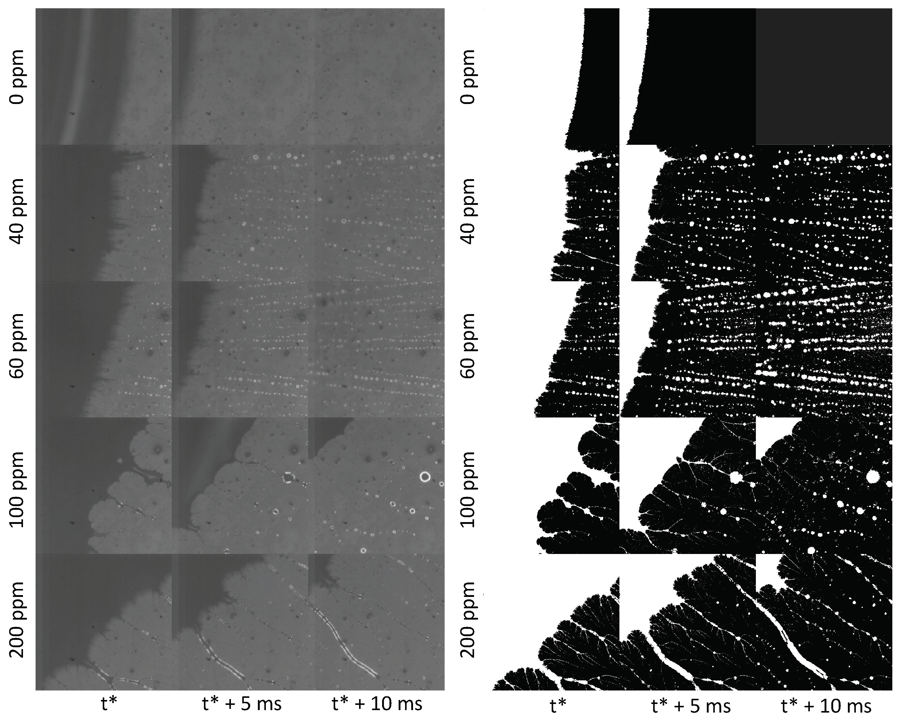
Here, the microscopic contact line morphology during dewetting of dilute polymer solution drops impacting on a hydrophobic surface is studied by high–speed microscopy, to get a deeper understanding of the origin of contact line forces. Experiments reveal the formation of transient microscopic dendritic structures generated by the receding contact line, which evolve in a similar fashion to the well–known beads–on–a–string mechanism [11]. Fingering and/or dendritic structures on a moving contact line were observed during spreading of surfactant solutions [12], evaporation of aqueous polymer solutions [13] and particle-laden droplets [14]; however, they have never been observed during rapid dewetting following drop impact. It is demonstrated that the shear flow in the liquid wedge near the contact line induces a second order coil–stretch transition of the polymer molecules leading to a significant increase of the local viscosity [15], which enables a quantitative estimation of the contact line friction. The proposed approach is substantially different from most of the existing studies, which interpret the same phenomenon as a consequence of a hypothetical but unrealistic elongational flow within the impacting drop.

2. Materials and Methods

Polymer solutions were prepared by dissolving polyethylene oxide (PEO) with average molecular weight of 4000 kDa (Sigma-Aldrich, St. Louis, MO, USA) in de-ionised water (Barnstead Easypure), at concentrations of 40, 60, 100 and 200 ppm. Since the overlap concentration of this polymer in water, calculated based on the Mark–Houwink correlation for the characteristic viscosity, is approximately 570 ppm [9,16,17], these solutions fall within the dilute regime. In this regime viscosity, η , and the relaxation time, τ , are approximately a linear and a square root function of the polymer concentration, respectively [18]. Unlike η and τ , the surface tension, σ , of PEO solutions is approximately the same as the solvent (∼70 mN/m) on the timescale of experiments [19].
The impact substrates were glass slides coated with Fluoropel PFC1302A (Cytonix Corp., Beltsville, MD, USA), a 2% fluoropolymer solution in low boiling point (135 C) fluorosolvent, with equilibrium contact angle for water of 105 ± 2 ; the Fluoropel coating was created by dipping glass slides into the liquid, and then dried at 90 C for 10 min to optimize adhesion.
Drops were released from a blunt hypodermic needle (gauge 21, i.d. 0.495 mm) suspended above the target surface. The equilibrium drop diameter (obtained from drop mass measurements) was in the range between 2.92 mm and 3.06 mm for all fluids. The impact velocity was controlled by adjusting the falling height between 20 mm and 140 mm, corresponding to impact Weber numbers between 13 and 110; the Weber number, W e = ρ v z 2 D 0 / σ , where ρ is the fluid density, v z denotes the vertical impact velocity, and D 0 denotes the equilibrium drop diameter prior to impact, is routinely used in the drop impact literature to characterise impacts through the competition between inertial and capillary forces, although it does not take into account the viscous dissipation. To account for viscous effects, one can introduce the Reynolds number R e = ρ v z D 0 / μ , where μ is the fluid viscosity, representing the ratio of inertial to viscous forces, and the Ohnesorge number O h = W e / R e , representing the ratio of viscous to capillary forces.
The contact line details during drop impact and recoil were recorded using a high-speed CMOS camera (Phantom v9.1) equipped with a Keyence VH-100ZR zoom lens (magnification range of 100×–1000×), at the speed of 5000 fps and a resolution of 480 × 480 pixels, corresponding to 1.46 μ m/pixel; the camera and the lens were arranged vertically looking at the substrate from below, while illumination was provided by an optic fiber halogen illuminator (ThorLabs, Newton, NJ, USA).

3. Results

3.1. Contact Line Morphology

The microscopic contact line morphology during drop retraction on a hydrophobized glass substrate for different concentrations of PEO and impact Weber number W e 110 is displayed in Figure 1, and compared with the contact line of a drop of pure water in the same experimental conditions. While the contact line of the water appears almost perfectly smooth, the contact line of the polymer solution drop exhibits large local deformations, and leaves behind microscopic liquid filaments as it sweeps the surface. Filaments are distributed uniformly around the contact line, and their width ranges between approximately 2 μ m and 30 μ m. The structure and density of these filaments depends on the polymer concentration in the fluid: for c < 100 ppm, one can observe linear filaments oriented in the radial direction, their density being increased with the polymer concentration; for c 100 ppm, there are less but thicker filaments, displaying numerous dendritic ramifications.
Filaments evolve displaying a pseudo capillary instability mechanism, until they locally break up into secondary microscopic droplets, in a similar fashion to the well-known bead-on-a-string capillary breakup mechanism characteristic of many viscoelastic fluids [11]. It is important to remark, however, that such resemblance is only visual, because while in conventional capillary breakup the flow in the liquid filament is purely elongational [20,21], the filaments observed in the present experiments are in contact with a solid surface, therefore they are in shear flow. On the reverse of the coin, the appearance of a bead-on-a-string breakup dynamics suggests that polymer stretching does occur also in shear flow, as predicted theoretically by de Gennes [15]. At higher polymer concentrations, filaments are more stable therefore the breakup mechanism is less noticeable on the timescale of the experiment.
This complex morphology, which can be observed only at the microscale, suggests that even from the macroscopic point of view the term contact line is not appropriate to indicate the drop edge, but one should rather use the expression apparent contact line, similar to the convention used for contact angles.

3.2. Estimation of the Polymer Elastic Force in a Liquid Wedge

The hydrodynamics of the liquid wedge near the contact line can be modelled as the flow between a fixed horizontal surface (the substrate) and a plate inclined at an angle θ (corresponding to the instantaneous value of the apparent dynamic contact angle), moving at velocity U, as shown schematically in Figure 2a. The minimum thickness of the liquid film, h 0 , must be no less than the unperturbed size of the polymer coils, R 0 ; for PEO molecules in water, one finds R 0 = 0.0888 M 0.5 = 178 nm, where M is the molecular weight [22], hence one can take an order of magnitude h 0 0.2 μ m. Polymer coils are subject to hydrodynamic interaction with the solvent, with a characteristic Zimm time τ 0 0.2 η s R 0 3 / k B T = 0.27 ms, and a Rouse time τ R 2 R h η s R 0 2 / π k B T = 0.41 ms, where η s is the solvent viscosity, k B is Boltzmann’s constant, T is temperature, and R h = 0.0145 M 0.57 = 84 nm is the radius of gyration.
In a reference frame originating on the contact point, the velocity components parallel and perpendicular to the substrate during drop retraction are, respectively, u U y / h ( x ) and v ξ ( θ ) x , where h ( x ) θ x is the liquid film thickness and ξ ( θ ) is a positive function of the apparent contact angle. The velocity gradient of this flow field can be split into its symmetrical part, A = 1 2 ( u y + v x ) = 1 2 ( U / h + ξ ) , associated with a pure deformation, and its anti-symmetrical part ω = 1 2 ( u y v x ) = 1 2 ( U / h ξ ) , associated with a pure rotation. Since ξ ( θ ) > 0 , ω / A < 1 therefore it is possible to have strong distortions of the polymer coils, even in the absence of elongational flow [15,23]. This corresponds to a second-order transition from coil to stretch conformation state, where the end-to-end distance of the polymer chain increases monotonously but steeply (i.e., with a constantly positive slope of the stretching ratio, l = r / L , where r is the polymer elongation and L the length of the fully stretched chain), with respect to the control parameter ξ ( θ ) (i.e., d l / d ξ > 0 ) [15]. Such transition, illustrated schematically in Figure 2b, is reversible and, unlike the first-order coil-stretch transition occurring in purely elongational flows, does not exhibit hysteresis.
For the two-dimensional steady-state shear flow introduced above, and following the classical finite extensibility approach [24], de Gennes obtained the following implicit relationship between the stretching ratio and the velocity gradient [15]:
l = 3 Z L 1 ( l ) 1 + 1 6 U h + ξ 2 τ 2 L 1 ( l ) 2 9 l 2 U h ξ τ 2
where Z is the number of monomers in one polymer chain, τ is the relaxation time, τ ( l ) τ R / ( 1 + 1 / l ) , and L 1 ( l ) is the inverse Langevin function, which can be estimated for example using Kroger’s approximation [25]:
L 1 ( l ) = 3 l ( l / 5 ) ( 6 l 2 + l 4 2 l 6 ) 1 l 2
The stretching ratio obtained from Equation (1) can be used to calculate the recall entropic force of a stretched polymer coil. In the dumbbell model, where the chain is represented by one single spring of fractional extension l = r / L , the restoring force is written as [15,24]:
F = k B T L R 0 2 L 1 ( l )

4. Discussion

To understand how the theoretical framework outlined in Section 3.2 above can be applied to the case of the receding contact line of a polymer solution drop after impacting onto a solid surface, one must observe the drop dynamics at the very begenning of the recoil stage after maximum spreading. 
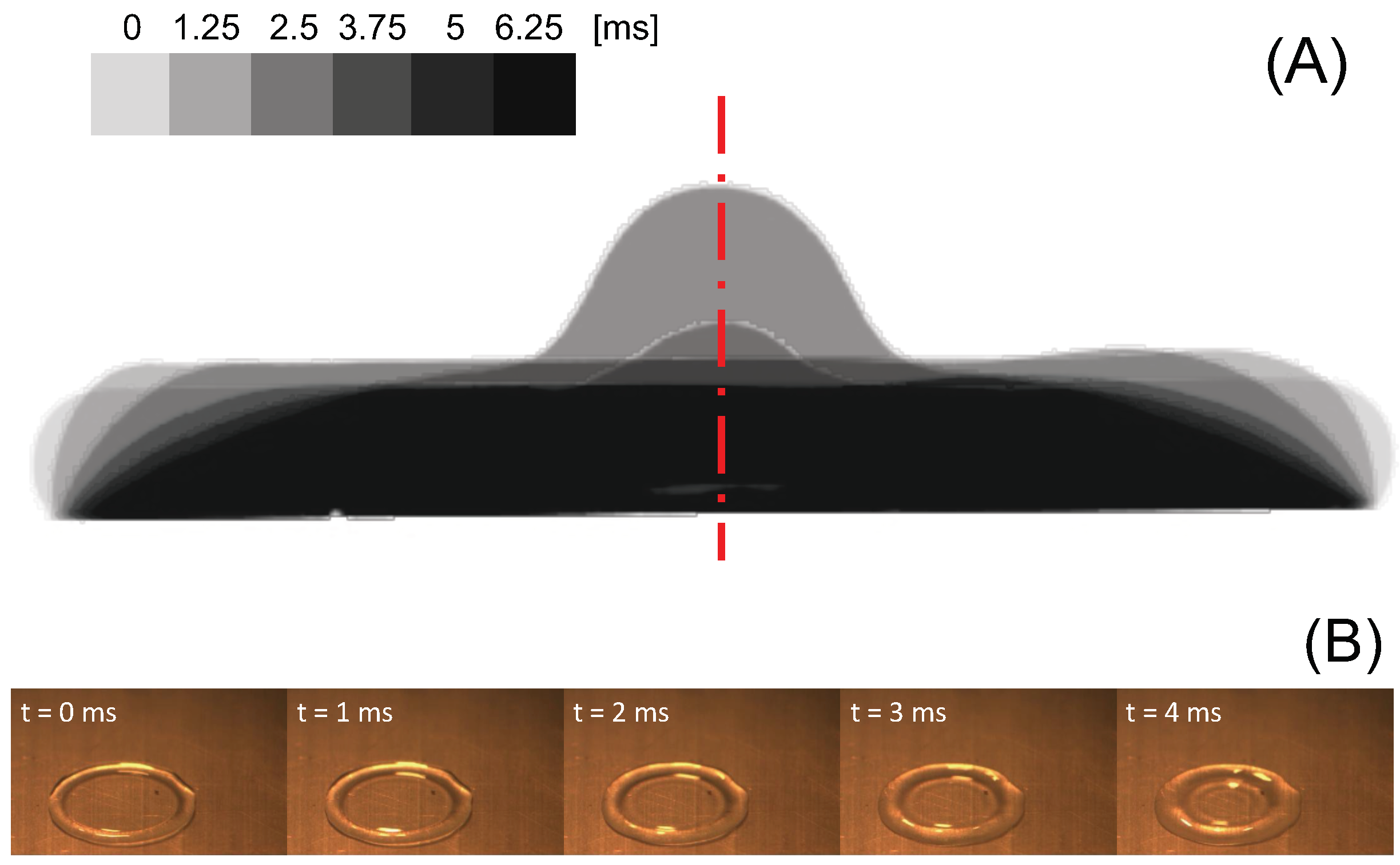
Figure 3A shows that at the beginning of recoil the contact line moves very slowly (although it is not pinned on the surface) compared to the displacement of the liquid free surface that defines the apparent contact angle, and causes the liquid in the rim, visible from the top vies displayed in Figure 3B, to flow back towards the centre of the drop. Previous works [7,8,9] show that while in water drops the fluid velocity is the same as the velocity of the receding contact line, in dilute polymer solution drops the bulk velocity of the fluid during retraction is two or three orders of magnitude larger than the contact line velocity. In particular, particle velocimetry measurements of the radial velocity in the lamella of a 200 ppm polyethylene oxide solution drop during retraction show the recoil velocity is approximately 300 mm/s, and grows linearly from the centre to the rim [8].
The drop dynamics illustrated in Figure 3 suggests the simple two-dimensional shear flow described in Figure 2a does not describe the flow field in the retracting drop adequately, but one should consider the unsteady boundary layer flow on the target surface, with a shear velocity gradient that can be approximated as:
u y u y y = 0 2 U ( x ) h ( x )
where U ( x ) and h ( x ) are the instantaneous free stream velocity in the radial direction and the boundary layer thickness at a distance x from the contact point, respectively.
Since the fluid is radially flowing back towards the drop centre, conservation of mass implies that in the first stages of recoil the velocity magnitude increases, so that v x > 0 . Thus, the ratio between the anti-symmetric and the symmetric part of the velocity gradient tensor is smaller than unity, which triggers the second-order coil-stretch transition as discussed above [15,23]. Moreover, in a boundary layer u y v x , therefore the polymer molecule fractional stretching given by Equation (1) does not depend significantly on the radial velocity gradient of the vertical velocity component, v x .
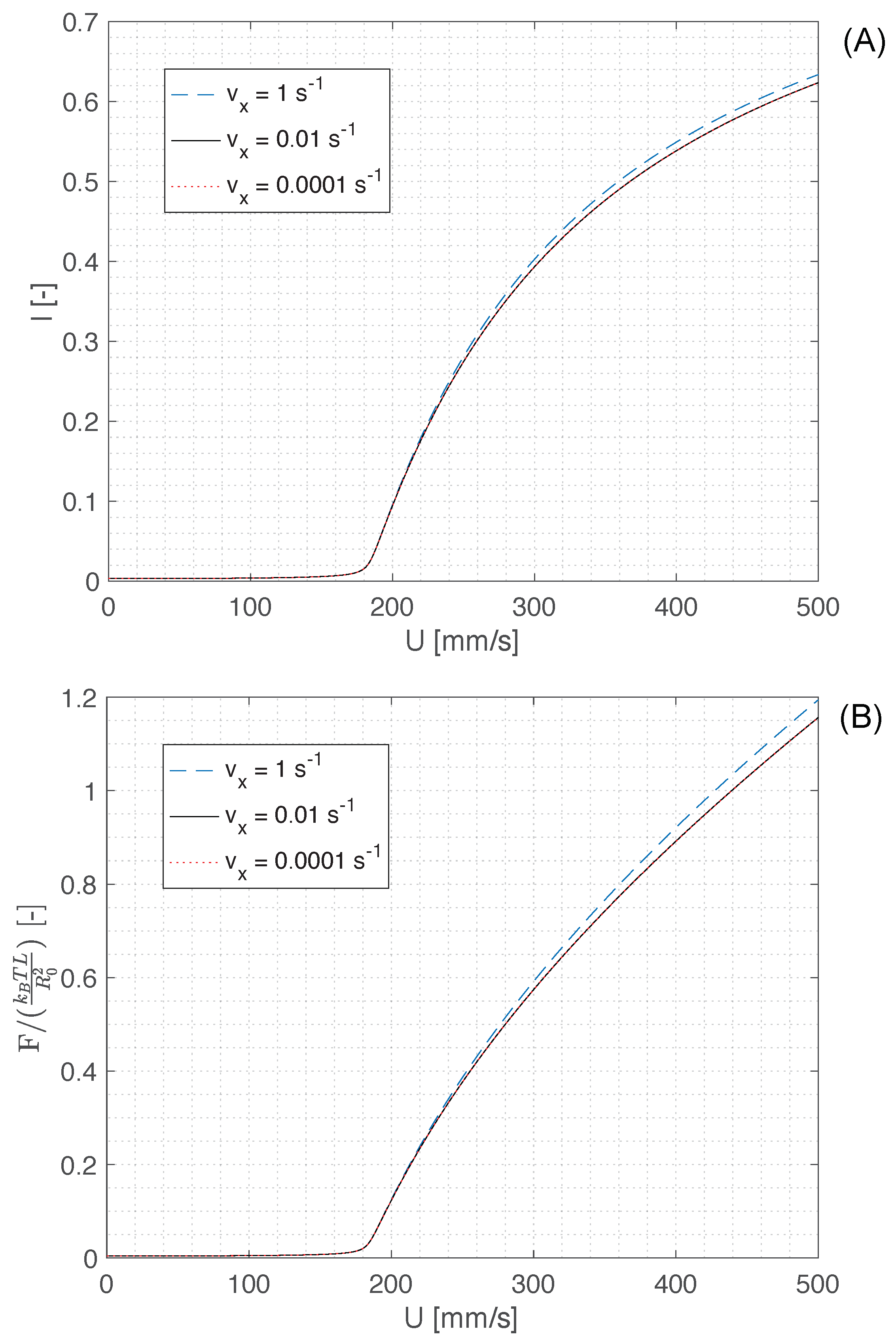
The numerical solution of Equation (1) for a boundary layer of thickness h 0.2 μ m (i.e., just above the polymer coil size R 0 ), and the corresponding recall force of a single polymer molecule (Equation (3)) are displayed in Figure 4A,B, respectively. These figures suggest that, irrespective of the magnitude of the gradient of the vertical velocity component v x , an appreciable stretching of polymer molecules and consequently a buildup of the recall force occur for velocities U 200 mm/s. Since the radial velocity in the lamella is of the order of 300 mm/s [8], and the velocity of the fluid in the rim is even faster as the rim flows over the lamella during recoil (see Figure 3B), one can conclude the shear flow near the contact line of the recoiling drop is sufficient to trigger the supercritical coil-stretch transition and cause a large deformation of polymer molecules, which can reach a mean fractional extension l 0.5 .
These results are confirmed both qualitatively and quantitatively by the work of Smith et al. [26], who directly observed the conformational dynamics of individual, flexible polymers in steady shear flow by the use of video fluorescence microscopy. In particular, it was found polymers reach an asymptotic mean fractional extension l 0.5 , characterised by a practically flat probability density between l 0.1 and l 0.7 [26]; this is also consistent with the direct observation of stretched DNA molecules [7] and of thin liquid filaments behind the receding contact line (Figure 1).
Thus, at the beginning of drop recoil, which occurs when the contact angle is still > 90 , the partially stretched polymer molecules on the de-wetted substrate induce a recall force on the receding contact line, opposed to the contact line velocity; this can be interpreted, from a macroscopic point of view, as an additional, dissipative force acting on the contact line and opposed to its movement, or an effective contact line friction. Figure 5 displays a schematic of the contact line forces in case of a drop of a pure fluid (Figure 5A) and in case of a dilute polymer solution (Figure 5B). Since the drop-surface system is not at thermodynamic equilibrium, the Young-Laplace equation γ S V = γ S L + γ L V cos θ (where γ S V , γ S L and γ L V are the solid-vapour, solid-liquid, and liquid-vapour interfacial tensions, respectively, and θ is the equilibrium contact angle) is not applicable. However, the contact line displacement is driven by surface forces, therefore one can write the following inequality:
γ S L + γ L V cos θ a p p > γ S V
where θ a p p is the apparent contact angle observed during drop retraction.
In other words, the net force on the contact line in the radial direction determines whether the drop spreads ( γ S V > γ S L + γ L V cos θ ) or recoils ( γ S V < γ S L + γ L V cos θ ), as shown schematically in Figure 5A. In the case of polymer solutions (Figure 5B), during drop recoil there is an additional resistive force due to the polymer chains stretching, F P , so that the condition for recoil becomes:
γ S L + γ L V cos θ a p p > γ S V + F P
If the magnitude of the polymer force (per unit length of the contact line) is comparable to the liquid surface tension, γ L V , the additional resistive force on the contact line is compensated by a significant reduction of the apparent contact angle, which is precisley what one can observe experimentally [6,27].
In order to estimate the magnitude of the polymer force per unit lenght of the contact line, one can evaluate an average value of the recall force of a single polymer molecule, given by Equation (3), and multiply it by the number of stretched molecules in a vertical liquid wedge near the contact line.
Figure 4A suggests that for the measured fluid velocity during recoil [7,8] the fracional stretching of polymer molecules is approximately 50%, and the same value can be estimated on the basis of the direct observation of the conformational dynamics of individual polymers in steady shear flow [26]. The corresponding value of the inverse Langevin function is L 1 ( 0.5 ) 1.8 .
The bulk number density of polymer coils in the fluid wedge is n = ρ p c N A / M , where ρ p is the polymer density, N A Avogadro’s number, c the volume concentration of the polymer, and M its molecular mass. However, the polymer coils that are stretched as the contact line sweeps the substrate align in a thin layer at the bottom of the fluid wedge, therefore their number scales as n .
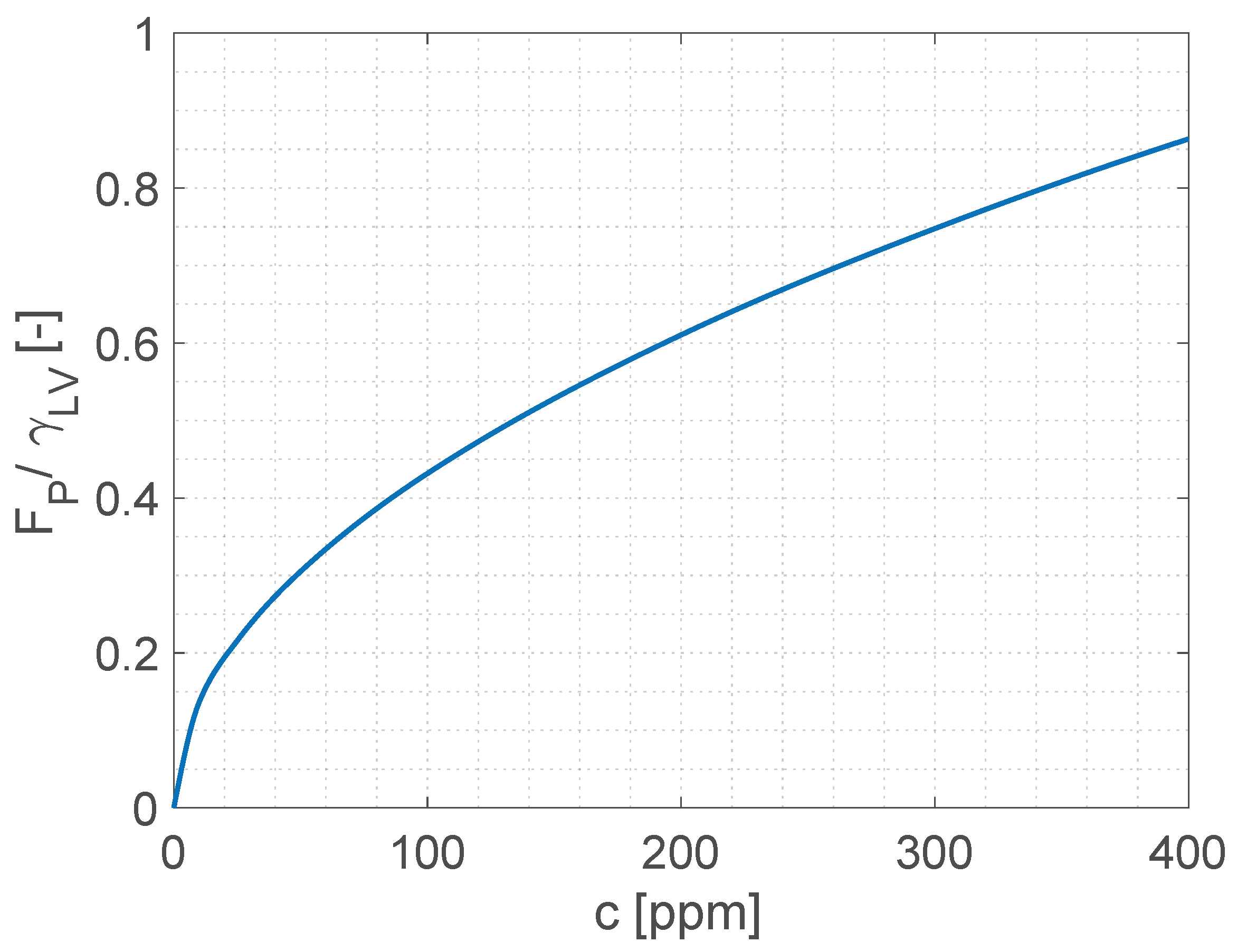
In conclusion, the overall average polymer force per unit contact line length is given by:
F P = 1.8 × n k B T L R 0 2
Figure 6 shows that the average polymer force per unit length, calculated using Equation (7) for polymer concentrations corresponding to dilute solutions, is comparable in magnitude with the surface tension of the polymer solution, therefore it can explain the reduction of the contact line retraction velocity observed experimentally. We note the force given by Equation (7) cannot be used directly as an additional term in a Young-Laplace force balance because the system is very far from equilibrium, therefore the apparent contact angle is not thermodynamically significant. However, the proposed approach provides a quantitative explanation of the phenomenon from first principles without any empirical parameters, and without the need to introduce fictitious elongational flows or other artefacts.

5. Conclusions

The receding contact line of dilute polymer solution drops after impact on a hydrophobic solid surface exhibits a peculiar morphology, consisting of transient microscopic dendritic structures generated by the receding contact line, which evolve in a similar fashion to the well–known beads–on–a–string mechanism, although in this case the observed liquid filaments are stretched due to a shear flow instead of a purely elongational flow. These structures indicate the radial flow in the recoiling drop induces a supercritical coil-stretch transition in the polymer molecules, and consequently the contact line is subjected to an additional dissipative force opposing its receding movement.
The magnitude of this dissipative force can be estimated using the classical finite extensibility approach, and is comparable to the magnitude of the surface forces that cause the drop recoil. The proposed approach provides a quantitative explanation of the phenomenon from first principlaes without any empirical parameters, and without the need to introduce fictitious elongational flows or other artefacts.

Supplementary Materials

The following supporting information can be downloaded at: https://www.mdpi.com/article/10.3390/colloids6010005/s1. Video S1: Detail of the receding contact line of a pure water drop after impact on a fluorinated surface. Video S2: Detail of the receding contact line of a 40 ppm PEO solution drop after impact on a fluorinated surface. Video S3: Detail of the receding contact line of a 60 ppm PEO solution drop after impact on a fluorinated surface. Video S4: Detail of the receding contact line of a 100 ppm PEO solution drop after impact on a fluorinated surface. Video S5: Detail of the receding contact line of a 200 ppm PEO solution drop after impact on a fluorinated surface.

Funding

This research received no external funding.

Institutional Review Board Statement

Not applicable.

Informed Consent Statement

Not applicable.

Data Availability Statement

Original videos available as supplementary material.

Conflicts of Interest

The author declares no conflict of interest.

References

  1. Bergeron, V.; Bonn, D.; Martin, J.; Vovelle, L. Controlling droplet deposition with polymer additives. Nature 2000, 405, 772–775. [Google Scholar] [CrossRef] [PubMed]
  2. Crooks, R.; Cooper-White, J.; Boger, D. The role of dynamic surface tension and elasticity on the dynamics of drop impact. Chem. Eng. Sci. 2001, 56, 5575–5592. [Google Scholar] [CrossRef]
  3. Bartolo, D.; Boudadoud, A.; Narcy, G.; Bonn, D. Dynamics of non-Newtonian droplets. Phys. Rev. Lett. 2007, 99, 174502. [Google Scholar] [CrossRef]
  4. Rozhkov, A.; Prunet-Foch, B.; Vignes-Adler, M. Impact of water drops on small targets. Phys. Fluids 2002, 14, 3485. [Google Scholar] [CrossRef]
  5. Bertola, V. An experimental study of bouncing Leidenfrost drops: Comparison between Newtonian and viscoelastic liquids. Int. J. Heat Mass Transf. 2009, 52, 1786–1793. [Google Scholar] [CrossRef]
  6. Bertola, V. Effect of polymer additives on the apparent dynamic contact angle of impacting drops. Colloids Surfaces A Physicochem. Eng. Asp. 2010, 363, 135–140. [Google Scholar] [CrossRef]
  7. Smith, M.; Bertola, V. Effect of polymer additives on the wetting of impacting droplets. Phys. Rev. Lett. 2010, 104, 154502. [Google Scholar] [CrossRef] [Green Version]
  8. Smith, M.; Bertola, V. Particle velocimetry inside Newtonian and non-Newtonian droplets impacting a hydrophobic surface. Exp. Fluids 2011, 50, 1385–1391. [Google Scholar] [CrossRef]
  9. Bertola, V. Dynamic wetting of dilute polymer solutions: The case of impacting droplets. Adv. Colloid Interface Sci. 2013, 193–194, 1–11. [Google Scholar] [CrossRef]
  10. Smith, M.I.; Sharp, J.S. Origin of Contact Line Forces during the Retraction of Dilute Polymer Solution Drops. Langmuir 2014, 30, 5455–5459. [Google Scholar] [CrossRef]
  11. Oliveira, M.; Yeh, R.; McKinley, G. Iterated stretching, extensional rheology and formation of beads-on-a-string structures in polymer solutions. J. Non-Newton. Fluid Mech. 2006, 137, 137–148. [Google Scholar] [CrossRef] [Green Version]
  12. Cachile, M.; Cazabat, A.M. Spontaneous Spreading of Surfactant Solutions on Hydrophilic Surfaces: CnEm in Ethylene and Diethylene Glycol. Langmuir 1999, 15, 1515–1521. [Google Scholar] [CrossRef]
  13. Liu, G.; Zhang, C.; Zhao, J.; Zhu, Y. Study of the Morphology of the Three-Phase Contact Line and Its Evolution by Morphological Examination after Droplet Evaporation of Aqueous Polymer Solutions. Langmuir 2008, 24, 7923–7930. [Google Scholar] [CrossRef]
  14. Hadj-Achour, M.; Brutin, D. Fractal pattern formation in nanosuspension sessile droplets via evaporation-spreading on a glass substrate. Colloids Interface Sci. Commun. 2014, 1, 43–46. [Google Scholar] [CrossRef] [Green Version]
  15. de Gennes, P.G. Coil-stretch transition of dilute flexible polymers under ultrahigh velocity gradients. J. Chem. Phys. 1974, 60, 5030. [Google Scholar] [CrossRef]
  16. Bertola, V. Effect of polymer concentration on the dynamics of dilute polymer solution drops impacting on heated surfaces in the Leidenfrost regime. Exp. Therm. Fluid Sci. 2014, 52, 259–269. [Google Scholar] [CrossRef]
  17. Bailey, F.E.; Koleske, J.V. Poly(Ethylene Oxide); Academic Press: New York, NY, USA, 1976. [Google Scholar]
  18. Kalashnikov, V.N.; Askarov, A.N. Relaxation time of elastic stresses in liquids with small additions of soluble polymers of high molecular weights. J. Eng. Phys. 1989, 57, 874–878. [Google Scholar] [CrossRef]
  19. Glass, J.E. Adsorption Characteristics of Water-Soluble Polymers. II Poly(ethy1ene oxide) at the Aqueous-Air Interface. J. Phys. Chem. 1968, 72, 4459–4467. [Google Scholar] [CrossRef]
  20. Eggers, J. Nonlinear dynamics and breakup of free-surface flows. Rev. Mod. Phys. 1997, 69, 865–930. [Google Scholar] [CrossRef] [Green Version]
  21. Eggers, J.; Villermaux, E. Physics of liquid jets. Rep. Prog. Phys. 2008, 71, 036601. [Google Scholar] [CrossRef]
  22. Brandrup, J.; Immergut, E.H.; Grulke, E.A.; Abe, A.; Bloch, D.R. Polymer Handbook, 4th ed.; John Wiley & Sons: Hoboken, NJ, USA, 2005. [Google Scholar]
  23. Lumley, J. Drag reduction in turbulent flow by polymer additives. J. Polym. Sci. Macromol. Rev. 1973, 7, 263–290. [Google Scholar] [CrossRef]
  24. Peterlin, A. Hydrodynamics of linear macromolecules. Pure Appl. Chem. 1966, 12, 563–586. [Google Scholar] [CrossRef]
  25. Kroger, M. Simple, admissible, and accurate approximants of the inverse Langevin and Brillouin functions, relevant for strong polymer deformations and flows. J. Non-Newton. Fluid Mech. 2015, 223, 77–87. [Google Scholar] [CrossRef] [Green Version]
  26. Smith, D.E.; Babcock, H.P.; Chu, S. Single-Polymer Dynamics in Steady Shear Flow. Science 1999, 283, 1724–1727. [Google Scholar] [CrossRef] [PubMed] [Green Version]
  27. Bertola, V.; Wang, M. Dynamic contact angle of dilute polymer solution drops impacting on a hydrophobic surface. Colloids Surfaces A Physicochem. Eng. Asp. 2015, 481, 600–608. [Google Scholar] [CrossRef]
Figure 1. Microscopic contact line morphology during drop retraction on a hydrophobized glass substrate for different concentrations of PEO and impact Weber number W e 110 . (Left panel): raw images; (right panel): the same images enhanced by background subtraction, histogram equalization and conversion to binary. Each frame has a size of 700 μ m. See original videos in supplementary material.
Colloids 06 00005 g001
Figure 2. (a) Schematic of the liquid wedge near the contact line and (b) schematic of supercritical coil-stretch transition [15].
Colloids 06 00005 g002
Figure 3. (A) Stroboscopic side view of a PEO aqueous solution drop ( D 0 3 mm) impacting on a PTFE surface at the beginning of recoil after maximum spreading ( c = 200 ppm; W e = 45 ; D m a x / D 0 2.2 ). The gray levels in region near the contact line correspond to the time since maximum spreading. (B) Top view of the same drop showing the toroidal rim during the first 4 ms of recoil after maximum spreading.
Colloids 06 00005 g003
Figure 4. Polymer fractional elongation (A) and dimensionless recall force (B) as a function of shear velocity U, for a shear layer thickness h 0.2 μ m and different magnitudes of the radial velocity gradient v x .
Colloids 06 00005 g004
Figure 5. Forces acting on the receding contact line for a drop of a pure fluid (A) and for a drop of a dilute polymer solution (B).
Colloids 06 00005 g005
Figure 6. Average polymer stretching force per unit length (Equation (7)), normalized with respect to the surface tension of the solution ( γ L V 70 mN/m [2,19]), plotted as a function of the polymer mass concentration.
Colloids 06 00005 g006
Publisher’s Note: MDPI stays neutral with regard to jurisdictional claims in published maps and institutional affiliations.

