1. Introduction
Composite materials have seen a significant rise in importance over the past few decades due to their superior mechanical properties, such as their high strength-to-weight ratios and stiffness, which make them fundamental for various structural applications. Originally used in high-tech sectors like aerospace and the military due to their cost and performance benefits, composites are now seeing increasing use in consumer goods and other industries. This widespread adoption underscores the importance of understanding and managing their inherent damage mechanisms, particularly barely visible impact damage (BVID), which poses significant challenges in terms of detection and repair.
Barely visible impact damage (BVID) is a significant concern for composite laminates due to its internal nature, as it remains concealed beneath the surface yet can critically undermine structural performance. Often resulting from low-velocity impacts, BVID causes delamination, matrix cracking, and fibre breakage without visible surface deformations [
1,
2,
3,
4]. This type of damage can reduce the compressive strength of composites by up to 70%, even in the absence of external signs [
5]. The complexity of diagnosing and addressing BVID is highlighted by its elusive nature, as traditional inspection methods may fail to detect these internal defects. To address this challenge, numerous studies have been conducted to develop advanced methodologies for the detection of such defects. For example, Katunin et al. focused on real composite structures, considering failure mechanisms that occur during impact damage. They developed algorithms that extract relevant diagnostic information from ultrasonic B- and C-scans, as well as from tomographic 3D arrays. These arrays were used to validate the ultrasonic reconstructed damage locations, significantly improving the detectability of BVID in tested structures. This approach can be particularly valuable for NDT operators when they are evaluating the results of structural inspections [
6].
Similarly, Polimeno et al. introduced a novel NDT approach based on monitoring the nonlinear elastic behaviour of damaged materials. They investigated two methods: single-mode nonlinear resonance ultrasound (NRUS) and nonlinear wave modulation spectroscopy (NWMS). Their methods were tested on composite plates with unknown mechanical properties, damage size, and magnitude. Both techniques successfully identified the nonlinearities introduced by the damage, demonstrating high sensitivity and promising potential for future applications [
7].
Moreover, Tabatabaeian et al. explored the use of deep learning models for BVID detection. They trained, validated, and tested four different deep learning models to detect BVID from images of impacted and non-impacted surfaces. The results showed that all four networks were effective at detecting BVID, with sensor-integrated samples reducing the training time and improving the accuracy. Among the models, ResNet achieved the highest accuracy, making the proposed method a fast, cost-effective, and accurate tool for monitoring the structural health of composite structures in real-world applications [
8].
These studies highlight the continuous efforts to enhance BVID detection through innovative technologies and methodologies, aiming to improve the safety and reliability of composite structures. Once damage is detected, effective repair methods are essential to restore the structural integrity and performance of the composites. There are several methods that can be used to repair composite structures affected by BVID, each with its own advantages and challenges. Traditional repair techniques include scarf and bonded patch repairs, where the damaged area is meticulously removed and replaced with a new patch. Scarf repairs, for instance, involve creating a tapered surface to ensure a larger bonding area, which enhances the repair’s effectiveness. Similarly, bonded patches, whether soft or hard, are used to restore the integrity of the composite material [
9,
10,
11,
12,
13]. The hot bonding technique represents an innovative approach for composite repair, wherein damaged layers are removed, and repair patches are applied using adhesive films and cured with heat and pressure [
14]. This method, while effective, requires precise execution and a skilled workforce.
An alternative to traditional methods is resin injection, which simplifies the repair process by injecting resin into the damaged area to consolidate the delaminated layers and form bonds between them. This method is particularly advantageous in the automotive sector due to its practicality and effectiveness. Resin injection allows repairs to be conducted even when there is limited access to the damaged area and often requires only a single vent for resin introduction, which streamlines the repair process and reduces the need for extensive heating equipment, making it a cost-effective solution for automotive applications.
Recent studies have highlighted significant advancements in resin injection techniques tailored to automotive composites, addressing the growing demand for effective repair methods in the automotive industry [
15]. Venkateswaran et al. have reviewed two primary repair techniques, scarfing repair and injection repair, that show promise for application in the automotive sector. Their work compiles various research studies on these repair methods, detailing the processing steps involved and highlighting the potential of non-destructive techniques for damage identification and repair assessment [
16]. Similarly, Robert S. Pierce et al. have explored the use of low-viscosity resin injection repairs as an effective method for restoring the compressive strength of delaminated composite structures. Their research extends this technique to the repair of dry spot defects in thick Carbon Fibre-Reinforced Polymer (CFRP) laminates and skin disbonds in Glass Fibre-Reinforced Polymer (GFRP) foam sandwich structures. The study demonstrates that these injection repairs, conducted under a vacuum with minimal material removal and surface preparation, offer a faster and more reliable solution compared to traditional methods. The use of infrared thermography validated the degree of resin infiltration, confirming the effectiveness of this repair approach for automotive composites [
17].
However, injection repair techniques are not only being explored in the automotive sector. Studies are also underway in other sectors, such as aerospace and land transportation, to improve these techniques. For example, Hautier et al. investigated composite repair methods through liquid resin infiltration, demonstrating the effectiveness of these techniques in repairing internal defects without the need for extensive surface preparation [
18]. Lai et al. explored using resin injection to repair low-velocity impact damage in CFRP laminates, highlighting the effect of drilling holes to facilitate resin injection and improve the mechanical properties of damaged materials [
19]. In another study, they optimized repair parameters using the Taguchi method, further enhancing the effectiveness of the in situ approach to repairing damaged CFRP laminates [
20]. Thunga et al. examined the use of bisphenol E cyanate ester resin to repair carbon fibre/bismaleimide composite panels, showing that these techniques can be adapted for various industrial applications, including the transportation sector [
21]. Rahman et al. (2019) developed a cost-effective and efficient resin-injection device for repairing damaged composites, emphasizing its practical applications in various industrial contexts [
22]. Other studies, such as those by Prashant Moghe et al. (2015) and Russell and Bowers, have characterized and further developed resin-injection techniques, demonstrating their potential across different composite materials and applications [
23,
24]. These studies demonstrate that injection repair is a versatile and continuously evolving technique, which can be adapted to meet the specific needs of various industrial sectors, promote the use of advanced composite materials, and improve the sustainability and safety of structures.
This research investigates an innovative procedure based on local resin injection in delaminated CFRP plates which can be used to repair damage immediately and at low cost, reducing maintenance and transport interventions. Composite panels were produced with pre-impregnated epoxy resin and carbon fibre-stratified, put under a vacuum and cured in an oven at T = 40 °C for 16 h. The obtained samples were subjected to different test methods to evaluate the effect of the repair technique and the material recovery in terms of impact behaviour and damage without the need to carry out CAI tests. Part of each sample was impacted, repaired and then impacted another time. The other samples were only impacted twice. The low-speed impact tests were performed with constant energy of 20 J. The micro-injection technology requires one-sided access and only a single vent to introduce the resin within the delaminated area. Thanks to the ultrasound non-destructive technique that was used to detect the composite damages, the results demonstrate that this method is able to improve the residual strength, reducing the delamination damage.
2. Materials and Methods
2.1. Materials Preparation
The composite plates used in the experiments were made from carbon fibres pre-impregnated with biaxial/TC-EP250TU/2-1/CBX200/47127, which was suitable for aeronautical and automotive composite components, and semi-toughened epoxy resin EPOLAM 2031 produced by Axson Technologies. These so-called pre-pregs were stored in cold rooms at T = −18 °C. For the production of composites, once stratified, they were left to cure at T = 40 °C for 16 h. Their physicochemical and mechanical properties are listed below (
Table 1) [
25].
The composites produced were symmetrical and balanced with a stratification ± 45° and had a thickness of 3.2 ± 0.25 mm. Coupons were cut from the plate with a nominal size of 100 mm × 150 mm.
The epoxy resin SX10-EVO by Mates Italiana was selected for the repair process due to its excellent compatibility with the composite materials and its low viscosity, which facilitates effective resin infiltration. This resin is particularly well suited for the repair of composite panels, as it matches the constituents of the coupon and ensures optimal bonding. Moreover, the SX10-EVO resin cures at room temperature, making it advantageous for practical, on-site repairs by simplifying the process and reducing the need for specialized equipment.
2.2. Low-Velocity Impact Tests
The low-velocity impact tests were carried out according to ASTM standard D7136 [
26] by a Ceast/Fraktovis MK4 instrumented testing machine equipped with a DAS 4000 digital acquisition system with a steel impactor with a hemispherical nose of 19.8 mm in diameter. To prevent multiple impacts, the striker was caught on the rebound by a brake that was available in the test apparatus. The minimum mass with which a test can be carried out is 3.640 kg, equal to the sum of the mass of the carriage (2.920 kg) and that of the firing pin. The value of the impact weight can be increased with the help of additional masses of known value and, by combining it appropriately with the fall height, the desired energy level for performing the test can be achieved. The firing pins consist of a cylindrical bar whose tip can be hemispherical with a diameter of 19.8 mm. Inside the tip of the firing pin is a strain gauge that allows the detection of the force of the impact. The acquisition unit allows a quick adjustment of the test parameters, such as the hammer, the type of firing pin, the sampling time, and the impact height. In addition, it calculates the impact energy and the impactor’s speed and allows the construction of force–displacement graphs. Impact energy U = 20 J was selected (with a mass of 3.64 kg and a speed of 3.31 m/s). The specimen was supported on a rigid platform and fixed by four clamps with rubber tips, as suggested by the standard ASTM standard D7136.
Impact energy U = 20 J was selected (with a mass of 3.64 kg and a speed of 3.31 m/s) to induce specific damage. Three test conditions were chosen to evaluate impact performances, damage extension and the repair technique. In particular, three macro-typologies tests were carried out and are referred to below:
IMP: the sample was impacted one time.
2IMP: the sample was impacted two times at the same energy value.
IMP-RIP-IMP: the sample was impacted, repaired and impacted another time at the same energy value.
Usually, a CAI test is used to test composite residual strength after an impact [
5], but in this paper, the 2IMP test and the IMP-RIP-IMP test were selected to evaluate the effect of the repair concerning the IMP test. Thus, the material’s recovery is evaluated in terms of impact behaviour and damage.
2.3. Ultrasound Technique
After each impact test, the damage was observed and measured by an ultrasonic technique. An analysis based on the absorption phenomenon related to the material structure was useful for characterizing the material and identifying porosity defects. An M2M Multi Pocket system, characterized by a linear phased array probe with 64 elements at 5 MHz, was used for the ultrasonic scans. C-scan inspections allow a plane view of specimens to be obtained and allow the internal damage to be reconstructed along with the thickness. The propagation velocity of the ultrasound waves in the CFRP tested is recorded as equal to 2500 m/s and it is registered.
2.4. Morphology of the Impacted Surface
Visual inspections and indentation depth measurements performed using an Olympus Confocal microscope OLS5000, collected in correspondence with the impacted areas, facilitated some useful considerations about the damage propagation phenomena of the plastic deformation (indentation, I) and the consequent mechanical properties of panels. The OLS5000 microscope is a confocal microscope equipped with an x-y-z moving table and software that permits the acquisition of 3D profile in correspondence with the impacted point. In this way, the maximum profile weight and indentation depth post-impact test are detected.
2.5. Injection Repair Set-Up and Procedure
A successful injection repair is highly dependent on the choice of resin and the methodology employed. The resin should have good wettability on the composite surface and low viscosity to ensure effective infiltration between the delaminated layers after injection. Additionally, it must develop strong adhesive properties to restore the mechanical strength of the composite. Furthermore, the cured resin should possess a glass transition temperature and thermal degradation characteristics that closely match the composite panel and service temperature limits. For this study, an epoxy SX10 resin was selected due to its compatibility with the composite materials and its low viscosity. The resin cures at room temperature, making it suitable for practical, on-site repairs and facilitating an effective in-place repair process.
The proposed injection repair process, illustrated schematically in
Figure 1, offers several advantages over traditional techniques. Initially, the specimens are prepared by securing them onto a work surface using a specially designed frame. This ensures stability during the repair process. The central part of the work focuses on the impact point, where a circular pattern of holes is drilled (
Figure 2). These holes serve two primary purposes: cleaning the delaminated area and providing vents for the injected resin (
Figure 1). Traditional injection methods often lack this venting mechanism, leading to air becoming trapped and incomplete resin infiltration. By incorporating vent holes, the proposed method effectively eliminates air entrapment, which could otherwise obstruct resin flow within the delaminated layers. Before injecting the resin, any residual debris from the impact is removed using acetone and compressed air to ensure a clean bonding surface.
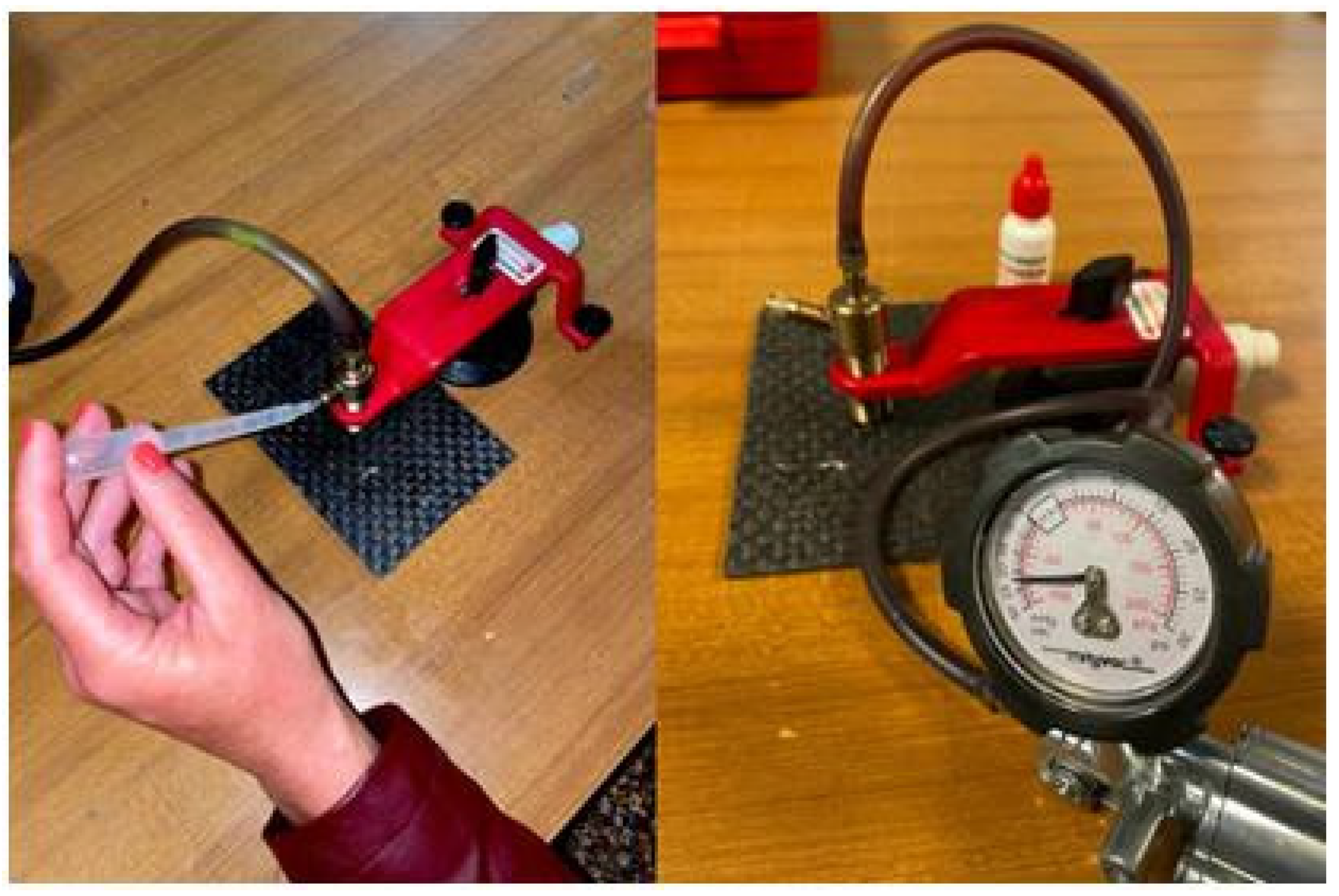
The injection apparatus is then precisely positioned over the impact point and secured to create a perfect seal. This step is critical to prevent resin leakage and ensure that the resin is directed into the delaminated areas. Once the pump is attached, the resin is injected through a secondary nozzle, ensuring thorough penetration and distribution of the resin within the damaged area (
Figure 2 and
Figure 3). The repaired panels are subsequently placed in an oven for curing at 40 °C for 16 h. This controlled curing process allows for optimal resin performance and adheres to the composite’s service requirements.
The proposed injection repair process, as illustrated in
Figure 2, represents a significant advancement over traditional methods by incorporating several innovative features designed to enhance repair effectiveness. Unlike conventional techniques, which often face challenges such as incomplete resin infiltration due to trapped air, this process integrates venting holes to ensure thorough resin distribution and minimize air entrapment. Lai et al. (2020) underscore the critical role of effective resin infiltration in restoring mechanical properties after impact damage, and this method addresses this need by employing targeted venting strategies to optimize resin flow and penetration [
19].
Furthermore, Hautier et al. (2010) and Thunga et al. (2014) emphasize the importance of precise resin application and proper ventilation to overcome common issues with traditional injection methods, such as incomplete filling and residual voids [
18,
21]. The approach includes a pre-cleaning step using acetone and compressed air to remove debris, thereby ensuring a cleaner bonding surface—an enhancement supported by Budhe et al. (2018), who highlight the significance of surface preparation on repair quality [
25].
Additionally, the use of a specialized injection apparatus with a secure sealing mechanism aligns with the recommendations of Prashant Moghe et al. (2015), who stress the necessity of precise control over resin application to achieve optimal repair outcomes [
23]. The controlled curing process at 40 °C for 16 h ensures that the resin reaches its full strength and meets the composite’s service requirements, a practise consistent with the findings of Lai et al. (2023), who optimize repair parameters for effective resin performance [
20]. This comprehensive approach effectively addresses several limitations inherent in traditional methods, including incomplete resin infiltration and inadequate venting, making this technique a more reliable and efficient solution for repairing barely visible impact damage in composite materials.
3. Results
In
Figure 4, closed load–displacement curves obtained with the three selected procedures are compared. The closed curves indicate the start of damage without perforation. The impact strength grows from zero to the maximum load, where the impactor returns and the force decreases. The area enclosed in the curves is equal to the absorbed energy, U
a, used by the material to create damage. So, as the area increases, the absorbed energy and global damage increase. In particular, the panels repaired before the second impact (IMP-RIP-IMP) return to their previous state, displaying properties like those of the panel that was subjected to only one impact. Also, the recorded maximum deformation (d
max) and maximum impact strength (F
max) values are similar for the IMP and IMP-RIP-IMP cases but lower than that observed for the panel that suffered two consecutive damages, 2IMP (
Table 2).
The enclosed area under the curve represents the absorbed energy, U
a, and the global damage index grows higher as the damage increases. For example,
Table 2 shows that the Ua from a single impact case (IMP) is lower than of an impacted-repaired-impacted panel (IMP-RIP-IMP), since the intermediate repair has restored its initial properties, considering that the composite behaves elastically. On the contrary, the energy absorbed by the double-impact panel (2IMP) is shallow compared to the U
a entity absorbed after the first impact, since the consequential damage causes the panel to behave like two glued thin laminates. Thin panels [
27] exhibit elastic behaviour, so most energy is elastically dissipated. At the same time, the extension of the damaged area propagates further.
Figure 5,
Figure 6,
Figure 7,
Figure 8 and
Figure 9 show images of the samples after impact. The damaged area consistently appears diamond-shaped, with the principal axes aligned with the warp–weft directions of the surface fabric layers (the horizontal and vertical directions in the pictures), where fibre fractures are observed. For the sample that was impacted only once (IMP) (
Figure 5), more significant damage is visible on the side that was in contact with the penetrator. In contrast, the other panels, including those that were impacted twice (2IMP) (
Figure 8 and
Figure 9) or impacted–repaired–impacted (IMP-RIP-IMP) (
Figure 6 and
Figure 7), exhibit more extensive damage on the back side of the panel. This pattern suggests that the single-impact sample (IMP) absorbed the impact energy in a way that concentrated damage near the point of impact, whereas the panels subjected to multiple impacts, including the repaired panel, showed damage that extended more towards the back side. The measurements taken after deployment confirm these observations, revealing fibre fractures along the warp–weft directions in the internal layers. The greater deformation on the lower surface of the twice-impacted (2IMP) samples and the IMP-RIP-IMP samples indicates that the energy distribution during the impact event differed, leading to distinct damage patterns.
An ultrasound C-Scan inspection was carried out along the plate in a strip containing the delaminated area to evaluate the repair technique’s suitability. In any case, as reported in the literature, the different kinds of damage can be collected in two big groups [
2,
3,
4,
5]: (a) external damage, which is characterized by different depths of the plastic deformation left by the impactor on the impacted surface, labelled as indentation; (b) internal damage, which is characterized by interlaminar fractures, delaminations produced by interlaminar stresses, fibre cracks (in-tension fibre breakage and in-compression fibre buckling) and matrix cracks. As accepted by a large number of authors that study composite laminate subjected to a concentrated force [
28,
29,
30], the evolution of the damage is driven by intralaminar tensile and shear cracks occurring in the layers farther from and nearer to the contact point depending on the thickness. From these cracks, delaminations were found at interfaces between plies.
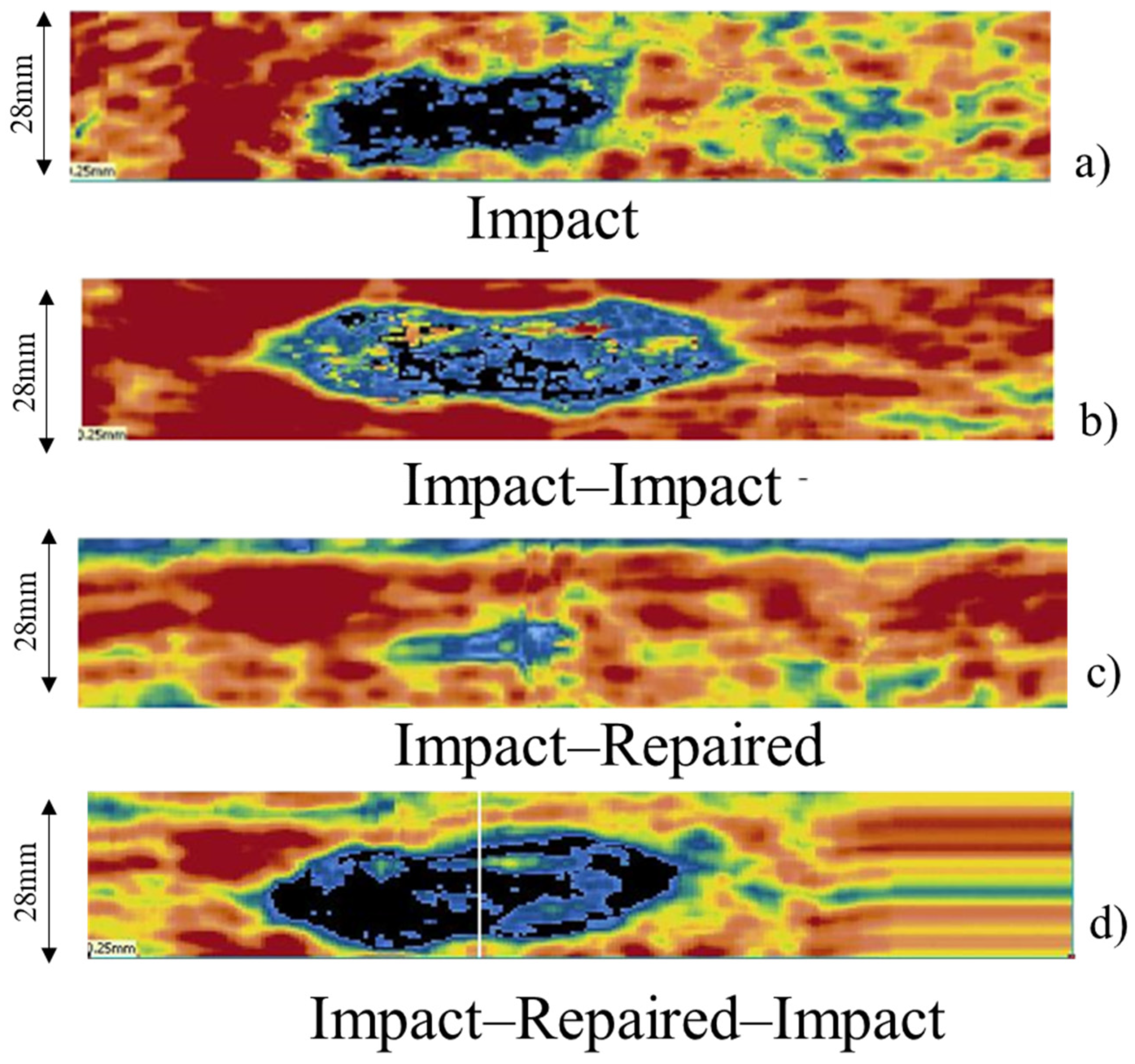
One of the most potentially dangerous aspects of the impact response of composite structures is the difficulty of detecting damage via visual inspection, even in the presence of considerable strength and rigidity losses. The specimen was scanned along the thickness ply by ply, and the result is reported in one plan as a C-scan image of the impacted, twice impacted, impacted–repaired, and impacted–repaired–impacted specimens (
Figure 10). C-scan inspections were applied to provide a plane view of specimens subjected to ultrasound analysis, and they were captured using ultrasonic evaluation before and after impact, providing a baseline for damage and identifying fabrication flaws. In particular, the C-scan shows a reconstruction of the damage, ply by ply, in one plane, so that all of the damage can be seen and measured. A more transparent image of the internal delamination was obtained by appropriately setting the gate. Using this image and the known dimensions of the scanned area and specimen, the size of the defect can be properly quantified. Echo Max (abs) was the detection mode used. Once the gate has been set, only the maximum peak that exceeded it was recorded in the scan. Based on the exceeding threshold of the gate (and therefore the signal amplitude), the C-scan had a different colour, which turned black if the signal could not exceed the established threshold. Each delaminated area was then imported into CAD software (Image J Wayne Rasband (NIH) version 1.54J), where it was bordered and measured. The damaged areas are represented in different colours and can be easily identified and measured.
Table 3 summarizes the absorbed energy (U
a), delamination area (A), and indentation depth (I) of the samples. The indentation depth, which measures the plastic deformation caused by the impactor, is the lowest for the IMP sample and the highest for the IMP-RIP-IMP sample.
Notably, the IMP-RIP test results show the smallest delaminated area, with only 129.876 mm2 of damage detected. This minimal damage underscores the effectiveness of the repair process in restoring the composite’s structural integrity. The reduced delamination indicates that the composite regained much of its original strength and stiffness, allowing it to better resist subsequent impacts. When the repaired sample was subjected to a second impact (IMP-RIP-IMP), it exhibited a delaminated area comparable to that of the panel that was impacted twice (2IMP). However, it absorbed energy similar to that of the panel that was impacted only once (IMP). This comparison highlights the high efficiency of the repair process, which effectively minimizes damage while preserving the composite’s durability and performance. Additionally, the greater indentation observed in the IMP-RIP-IMP panel further demonstrates the successful restoration of the material’s impact resistance after repair.
4. Conclusions
The proposed injection repair process demonstrates several advancements over traditional methods and proves effective in restoring the mechanical properties of composite materials impacted at low speeds. Key innovations include the incorporation of venting holes, and addressing common issues such as air entrapment and incomplete resin infiltration. This ensures thorough resin distribution within the delaminated layers, enhancing the overall effectiveness of the repair. The process also benefits from careful surface preparation and the use of a specialized injection apparatus, aligning with best practices recommended by experts in the field [
18,
19,
23].
The experimental results confirm that the proposed resin injection repair technique effectively restores the mechanical properties of composites subjected to low-speed impacts. The method demonstrated significant advantages in repairing damaged composite panels, particularly in the context of on-site repairs for the automotive sector. The use of a minimal quantity of resin not only facilitates efficient repair but also ensures that the composite’s configuration is closely restored to its original state.
The analysis of load–displacement curves (
Figure 3) and subsequent measurements of absorbed energy (U
a), delamination area (A), and indentation depth (I) reveal that the repair process significantly mitigates the impact of damage. Panels that are repaired before undergoing a second impact (IMP-RIP-IMP) exhibit performance characteristics similar to those of panels subjected to a single impact (IMP), underscoring the effectiveness of the intermediate repair in restoring mechanical strength. Although there is no precise correlation between absorbed energy and the delamination area, it is evident that the repair process effectively restores the composite’s initial configuration but does not entirely negate the previous damage endured.
The results support the technique’s effectiveness and highlight its potential for broader application in the automotive and aerospace industries.


