Article

Design of Type-IV Composite Pressure Vessel Based on Comparative Analysis of Numerical Methods for Modeling Type-III Vessels

Materials Research and Technology Department, Luxembourg Institute of Science and Technology, 5, rue Bommel, Z.A.E. Robert Steichen, L-4940 Hautcharage, Luxembourg
*
Author to whom correspondence should be addressed.
J. Compos. Sci. 2024, 8(2), 40; https://doi.org/10.3390/jcs8020040
Submission received: 8 December 2023 / Revised: 3 January 2024 / Accepted: 19 January 2024 / Published: 23 January 2024

Abstract

:
Compressed gas storage of hydrogen has emerged as the preferred choice for fuel cell vehicle manufacturers, as well as for various applications, like road transport and aviation. However, designers face increasing challenges in designing safe and efficient composite overwrapped pressure vessels (COPVs) for hydrogen storage. One challenge lies in the development of precise software programs that consider a multitude of factors associated with the filament winding process. These factors include layer thickness, stacking sequence, and the development of particularly robust models for the dome region. Another challenge is the formulation of predictive behavior and failure models to ensure that COPVs have optimal structural integrity. The present study offers an exploration of numerical methods used in modeling COPVs, aiming to enhance our understanding of their performance characteristics. The methods examined include finite element analysis in Abaqus, involving conventional shell element, continuum shell element, three-dimensional solid element, and homogenization techniques for multilayered composite pressure vessels. Through rigorous comparisons with type-III pressure vessels from the literature, the research highlights the most suitable choice for simulating COPVs and their practicality. Finally, we propose a new design for type-IV hydrogen composite pressure vessels using one explored method, paving the way for future developments in this critical field.

1. Introduction

Composite overwrapped pressure vessels (COPVs) have become an efficient solution and mature technology for hydrogen storage. Therefore, the need to develop robust and accurate predictive models is increasing to obtain safer, cheaper, and lighter designs. Filament winding is the most used technique for type-IV composite vessel manufacturing. This process is complex and necessitates more developments as it was addressed by many authors [1,2,3,4,5,6]. For the advanced design and production of COPVs with optimum structural integrity, more emphasis should be placed on the netting design and the analysis of the fiber winding angle, ply thickness, manufacturing techniques, and novel fiber or lamina bonding materials.
Humber et al. [7] investigated the manufacturing angle of the filament winding process to optimize cylinders under buckling load. A genetic algorithm was applied to optimize each design for maximum axial buckling load and digital image correlation to measure the displacement, strains, thickness, and midsurface imperfections of different designs. Results from thickness measurements supported the fact that the helical cross-over zones act as regions of strain concentrations and, ultimately, as imperfections imprinted onto the cylinder.
The study introduced in [8] proposed methods for dome thickness distribution and the charge pressure of the liner for a 70 MPa type-IV hydrogen storage vessel. The netting theory was employed to design the layup of the cylindrical section. To evaluate the designed layup, various failure criteria were applied to precisely predict the failure of composite layers with finite element analysis (FEA). Kumar et al. [9] investigated the impact of the dome geometry on the stress distribution in composite pressure vessels. The stress is evaluated at the interface of the dome cylinder for each dome contour. Three different cases were investigated: (i) a polymer liner, (ii) a single layer of carbon–epoxy composite wrapped on a polymer liner, and (iii) a multilayer carbon–epoxy pressure vessel. Significant secondary stresses were observed at the dome–cylinder interface, which drastically affect the failure mechanism, especially for thick-walled composite pressure vessels. An asymptotic method was used to model carbon-fiber-reinforced polymers (CFRPs) in [10]. A multiscale procedure was established to bridge the different scales, namely, the microscopic model, mesoscopic model, and macroscopic model. As an application, the homogenized CFRP laminate was used to perform the mechanical analysis of type-III composite pressure vessels. The stress distribution and failure mechanisms and the burst strength were investigated in [11] using a parametric study of fiber wound composite vessels. The maximum strain criterion and Tsai–Wu failure criterion were applied. It was observed that the failure initiated at the spiral wound layer in the matrix part; then the matrix failure provoked the stiffness degradation and hence the fiber failure on the hoop wound layers, which ultimately led to the failure of the vessel. The authors in [12] introduced a numerical method that integrates the Matlab and Abaqus software programs to illustrate the impact of the dome on the mechanical performance of the composite pressure vessel. This approach significantly reduces the effort and time required to develop the finite element model. Methodologies to study the progressive failure of composite pressure vessels is introduced in [13,14,15,16,17]. The approach focuses on the debonding of the liner from the composite shell during the curing process and attempts to enhance the accuracy of the thickness of the composite layer in the dome region. Type-III composite overwrapped pressure vessels were investigated in [18] via filament winding of epoxy-impregnated carbon filaments over an aluminum liner where the pressure was applied progressively until the burst of the vessel. A progressive damage model was used to investigate the performance of the vessel numerically; then the results were compared with experimental data. A predictive damage analysis and a design model of hydrogen storage composite pressure vessels were developed in [19]. The methodology consists of continuum damage mechanics evolution and finite element modeling of the vessel mechanical response. At the mesoscale, a temperature-dependent stiffness reduction law for transverse matrix cracking is considered using the Eshelby–Mori–Tanaka approach, and a stiffness reduction law for the damage variable is considered using a self-consistent model. Fiber failure is predicted by a micromechanical rupture criterion. Hydrogen storage, delivery options, safety, and reliability of infrastructures are discussed and reviewed in [20,21,22]. Type-V pressure vessels were explored in [23], where the manufacturing feasibility of a two-piece composite pressure vessel was determined using automated fiber placement (AFP). While successfully validating critical dome thickness and predicting part mass accurately, manufacturing defects, such as wrinkles and a hole, were encountered. Testing revealed suboptimal hydrostatic pressure retention. The research highlights the need for addressing manufacturing issues and suggests future developments focusing on gap elimination, hoop reinforcement, alternative ply strategies, and advanced failure criteria considerations for improved structural performance and leakage prevention. Belardi and coauthors [24] introduced a bending theory for composite shells, offering a closed-form solution for analyzing the structural behavior of pressure vessels. Focusing on the transition zone between a cylindrical shell and heads, where membrane theory falls short, it reveals elevated stress fields. The analytical framework, validated through parametric studies, proves to be accurate and stable, making it a valuable tool for the preliminary design of composite pressure vessels, particularly for linerless type-V vessels. Designing the outer contour of composite pressure vessel domes is challenging due to varying angles and thicknesses. Existing methods lack consideration for the impact of preceding layer fiber stacking. The study introduced by [25] used an improved cubic spline function and a novel parabola method, accounting for stacking effects. The parabola method, simple and adaptable, demonstrates high consistency in modeling composite pressure vessels, proving to be valuable for design. The present research paper aims to conduct a comparative analysis of various numerical methods for modeling composite pressure vessels. The study’s goal is to provide a comprehensive understanding of the performance of different numerical methods, including finite element analysis in Abaqus with conventional shell element, continuum shell element, three-dimensional solid element, and homogenization methods for multilayered composite pressure vessels. The paper’s novelty lies in its systematic comparison of multiple numerical methods, providing valuable insights into their relative strengths and weaknesses. The paper is organized as follows: Section 1 provides an introduction to the topic and outlines the study’s objectives and rationale. Section 2 describes the materials and methods used in the study, including details of the numerical simulations performed. Section 3 and Section 4 present the simulation results and discuss their implications. In Section 5, we present the validation of a case study that applies to a type-IV tank. Finally, Section 6 summarizes the study’s main findings and suggests future research directions. For comparison purposes, we used WebPlotDigitizer (Version 4.6), developed by Ankit Rohatgi [26], to extract data from the literature. Additionally, we considered the background established by the authors in their previous works, such as [27,28].

2. Materials and Methods

2.1. Materials

The container resembles a bottle, featuring an aluminum liner. The cylindrical segment spans 366 mm, with two domes curving at 78 and 79 mm, exhibiting varying thicknesses. The inlet has an external diameter of 40 mm, and the cylinder’s internal diameter is 132 mm. Notably, the vessel’s single inlet introduces asymmetry, requiring careful consideration for boundary conditions in the modeling process. COPVs are produced through a filament winding process. To explore various numerical methods and suggest the most effective technique, it is crucial to compare our investigation with existing literature. We have chosen the experimental investigation presented in [18] as our reference. Consequently, the materials, geometry, and loading conditions are akin to those used in this reference. The study primarily deals with the design, modeling, and testing of multilayered COPVs designed for high-pressure gas storage. A load-bearing liner made of 34CrMo4 steel was used, and glass and carbon filaments were wound at a specific angle to construct fully overwrapped composite-reinforced vessels with different dome endings. These vessels were subjected to pressure loading until they reached burst pressure levels. Both experimental and numerical analyses were carried out, with the latter employing finite element analysis and a progressive damage model in Ansys commercial finite element software. Adhering to the reference, the stacking sequence employed for this comparison is [ ± 11 , 90 2 ] 3 , involving a total of 12 layers. The properties of the materials used in their investigations are summarized in Table 1.
It is noteworthy that, here, we are focusing on type-III COPVs for comparison reasons, and we will propose at the end of this study a new design of type-IV COPVs. The modeling will help to parameterize the filament winding process and the geometry of the COPV and then optimize the design before the manufacturing process. Overall, in the simulation section, we elucidate the principles, procedures, and distinctions between conventional elements, continuum shell elements, and solid elements in the context of structural modeling, particularly highlighting their usage, properties, and appropriate orientation.

2.2. Micromechanics Models

In our approach, micromechanics, specifically finite element homogenization (referred to as the hybrid method), replaces the need to model each layer individually. Utilizing the Micromechanics Plugin for Abaqus/CAE [29], we perform finite element simulations on the composite shell materials of the COPV. The comparison of RVE results with mean-field homogenization models or from RVE analyses [30,31] is possible. Our stress–displacement analysis on a unit cell, representing distinct layers with varying orientations, aims to determine the effective 3D elastic properties of the composite shell, including Young’s modulus, Poisson’s ratio, and shear modulus. Postprocessing using the plugin’s features allows for the calculation of homogenized material responses. These definitions are then applied in larger-scale analyses. Additionally, the solid-to-shell homogenization method determines effective shell section properties, including the ABD matrix, offering insights into the behavior of composite materials in various applications, such as lattice core sandwich panels, textile composites, or laminated composites in the studied COPVs.

2.3. Constitutive Models for the Liner and the Overwrapped Composite Layers

The 34CrMo4 steel liner material was defined as an isotropic elastoplastic material in Abaqus, using the bilinear isotropic hardening model for the plastic behavior. The true stress–true strain behavior of the liner was obtained from relevant literature, and the yield strength and tangent modulus of the bilinear isotropic model were calculated from the plastic behavior of the metal. These values are provided in Table 1. In addition to the liner material, the properties of the transversely isotropic glass-reinforced composite material were obtained from reference [18].
The Hashin failure criterion is a widely used method for predicting the initiation of damage in composite materials. This interactive failure theory can identify different types of damage modes, including fiber tension, fiber compression, matrix tension, and matrix compression. It is commonly used as a first-ply failure criterion in composite failure modeling and is even available as a built-in feature in the Abaqus software [32]. The Abaqus anisotropic damage model for unidirectional fiber-reinforced composites considers four different modes of failure: fiber rupture in tension, fiber buckling and kinking in compression, matrix cracking under transverse tension and shearing, and matrix crushing under transverse compression and shearing. This makes it a powerful tool for predicting the behavior of composite materials under various loading conditions. The initiation criteria have the following general forms:
Fiber tension ( σ ^ 11 0 ):
F f t = σ ^ 11 X T 2 ;
Fiber compression ( σ ^ 11 < 0 ):
F f c = σ ^ 11 X C 2 ;
Matrix tension ( σ ^ 22 0 ):
F m t = σ ^ 22 Y T 2 + σ ^ 12 S L 2 ;
Matrix compression ( σ ^ 22 < 0 ):
F m c = σ ^ 22 Y C 2 + σ ^ 12 S L 2 ;
In the above equations, X T denotes the longitudinal tensile strength; X C denotes the longitudinal compressive strength; Y T denotes the transverse tensile strength; Y C denotes the transverse compressive strength; S L denotes the longitudinal (or in-plane) shear strength; and σ ^ 11 , σ ^ 22 , and σ ^ 12 are components of the effective stress tensor, σ ^ , that is used to evaluate the initiation criteria and which is computed from
σ ^ = M σ ,
where σ is the true stress and M is the damage operator:
M = 1 ( 1 d f ) 0 0 0 1 ( 1 d m ) 0 0 0 1 ( 1 d s ) .
The effective stress, σ ^ , is a measure of the stress that acts over a damaged area and effectively resists internal forces. The scalar variables d f , d m , and d s in Equation (6) are internal (damage) variables that characterize fiber, matrix, and shear damage, which are derived from the damage variables d f t , d f c , d m t , and d m c , corresponding to the four modes previously discussed, as follows:
d f = d f t if σ ^ 11 0 , d f c if σ ^ 11 < 0 ,
d m = d m t if σ ^ 22 0 , d m c if σ ^ 22 < 0 ,
d s = 1 ( 1 d f t ) ( 1 d f c ) ( 1 d m t ) ( 1 d m c ) .
Before any damage takes place, the material exhibits linear elasticity, and the damage operator, M , is equal to the identity matrix, so σ ^ = σ . A value of 1.0 or higher of the initiation criterion (fiber tension: F f t , fiber compression: F f c , matrix tension: F m t , matrix compression: F m c ) indicates that the initiation criterion has been met. As soon as damage begins, the stiffness of the material is immediately reduced. The relationship between stress and strain for a damaged material is described by Equation (10) as follows:
σ = C d ε ,
where σ is the true stress, ε is the elastic strain, and C d is the damaged elasticity matrix, which has the form
C d = 1 D ( 1 d f ) E 1 ( 1 d f ) ( 1 d m ) ν 21 E 1 0 ( 1 d f ) ( 1 d m ) ν 12 E 2 ( 1 d m ) E 2 0 0 0 D ( 1 d s ) G 23 ,
where D = 1 ν 12 ν 21 ( 1 d f ) ( 1 d m ) , E 1 is Young’s modulus in the fiber direction, E 2 is Young’s modulus in the transverse direction, G 23 is the shear modulus, and ν 12 and ν 21 are Poisson’s ratios.
When a material reaches a damage initiation criterion, further loading will cause the material’s stiffness to degrade. The extent of degradation is controlled by damage variables, which can range from 0 (no damage) to 1 (complete damage). The evolution of the damage variables after damage initiation is based on the fracture energy dissipated during the damage process. Each damage variable evolves according to an equivalent displacement, which is expressed in terms of the effective stress components used in the initiation criterion for that damage mode. The detailed methodology for computing the damage variables for each failure mode is given in [32,33].

3. Numerical Simulations

3.1. Simulation Using 3D Elements

To model a tank using 3D elements, one must first consider a part representing the liner geometry with a varying section at the domes (see Figure 1). Next, several parts corresponding to the composite layers representing the filament-wound shell must be considered. During this process, it is important to account for the increasing dimensions of each layer due to the thickness of the preceding ply; this is vital to ensure proper assembly. A tie contact should be established between all the parts, and a homogeneous section and material orientation assignment should be attributed to each layer separately. After these steps have been completed, all classical steps of an Abaqus model must be defined. It is important to note that nonlinear C3D20R elements must be used for the liner and C3D8R elements for the composite wound layers when meshing the structure. Additionally, it is possible to consider only a quarter model due to symmetry. However, due to the impracticality of this method when using the Abaqus software, the usage of the 3D element model was limited only to the simulation of the bare liner. Indeed, we used the 3D element model only for the liner without the wound shell (bare liner) to evaluate its capacity because it is practical (only one layer); when we consider several layers of composite shell, the method becomes impractical. The convergence of the mesh was obtained for a full model using 66,240 quadratic hexahedral elements C3D20R and 460 quadratic wedge elements C3D15 corresponding to 317,041 nodes.

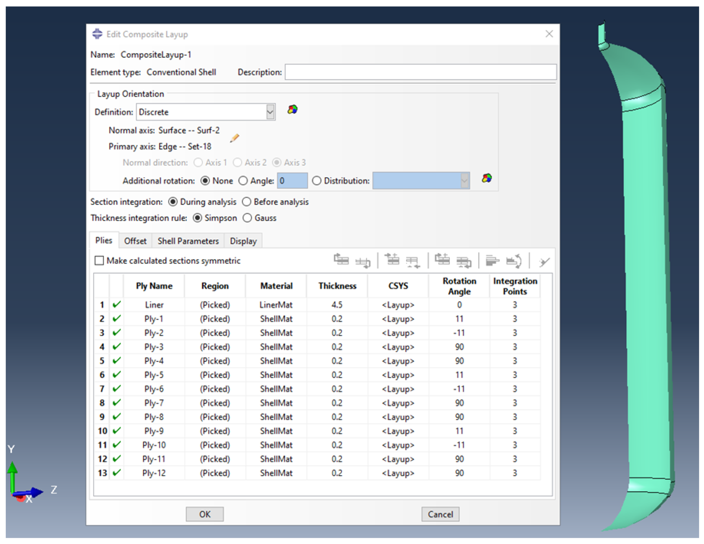
3.2. Simulation Using Conventional Shell Elements

In our model construction using conventional shell elements, we initially considered only the inner dimensions of the liner. Subsequently, we incorporated the filament winding staking by utilizing the Abaqus composite layup feature. This method requires the input of thickness, material, orientation angle, and the number of integration points for each layer. It is important to note that the liner part is treated as a composite ply with a constant thickness and a zero-degree orientation, as depicted in Figure 2. However, the varying thickness of the liner in the dome region, which was overlooked, will undoubtedly affect its behavior. A critical step in this process is assigning the layup orientation, which applies to all tank simulations. In our case, we used the axial direction as the zero reference orientation. For meshing, we employed S8R, an 8-node doubly thick curved shell element with reduced integration. Despite its simplicity and cost-effectiveness in terms of computational time and resources, this method has some limitations that we will discuss later. Due to its practicality, we utilized this method to simulate both the bare liner and the full tank. The convergence of the mesh was obtained for a full model using 6968 quadratic quadrilateral elements S8R and 52 quadratic triangular elements STRI65 corresponding to 21,061 nodes.

3.3. Simulation Using Continuum Shell Elements

To build a model using continuum shell elements, we divided it into two parts: one for the liner and the other for the composite shell. The first part accurately represents the liner’s geometry, including its varying thickness. The second part represents all the layers combined, accounting for their total thickness. The liner’s properties are introduced as a homogeneous section based on engineering constants and are meshed as a single layer using continuum shell elements. On the other hand, the composite shell properties are introduced using the Abaqus composite layup feature, with each of the twelve plies assigned a relative thickness of 1. The same procedure used in conventional shell elements is followed for the stacking sequence and orientation angles, as shown in Figure 3. The composite shell part is meshed using SC8R elements, which are 8-node quadrilateral in-plane general-purpose continuum shells with reduced integration, hourglass control, and finite membrane strains. This method is not only practical and straightforward to implement but also cost-effective in terms of computational time. We utilized this method to simulate both the bare liner and the full tank. The mesh converged using 18,920 linear hexahedral elements SC8R and 280 linear wedge elements SC6R corresponding to 19,200 nodes.

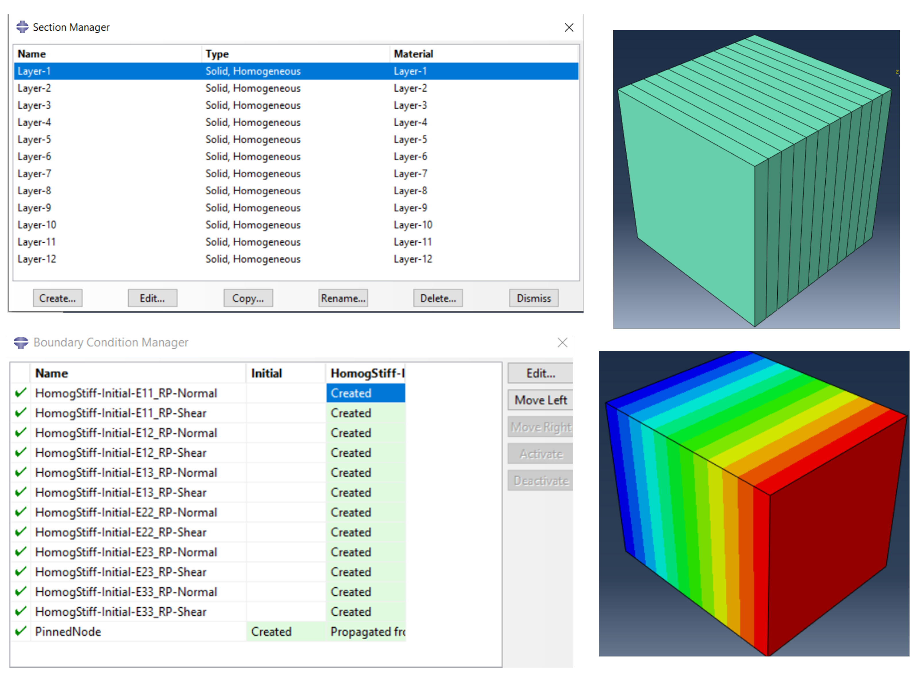
3.4. Simulation Using Mixed Method

This approach is referred to as a mixed method because it integrates the homogenization procedure outlined in Section 2.2 with one of the three previously mentioned simulation methods. Specifically, we first homogenize the composite shell part of the tank using the micromechanics method, then treat this part as a single layer with the effective properties obtained. Simulations can be conducted using any of the three previously described methods: conventional shell element, continuum shell element, and 3D element. As a result, the model consists of two layers representing the liner and the homogenized shell in all cases, making it straightforward to implement. However, one clear limitation is the absence of inter- and intralaminar states in the composite shell. It is worth noting that the effective properties of the homogenized composite shell are obtained as engineering constants suitable for both the 3D element model and the continuum shell element model, as well as an ABD stiffness matrix suitable for the conventional shell element model.
Figure 4 shows the Abaqus-based computational model used to determine the three-dimensional effective properties and the ABD matrix for both the solid-to-solid and solid-to-shell homogenization scenarios. This model represents a composite with a specific stacking sequence of ( ± 11 , 90 2 )3, as illustrated in Figure 2. Each layer within this sequence has a thickness of 0.2 mm, and the properties associated with these layers are detailed in Table 1. Table 2 reports the three-dimensional effective properties for the solid-to-solid homogenization, while Equation (12) provides the upper triangular part of the symmetric ABD matrix corresponding to the solid-to-shell homogenization.
ABD = 65924.9 12248.3 8.41842 × 10 4 74,100.3 14455.6 555.062 67909.2 6.76931 × 10 5 14455.6 86985.2 44.6329 12491.5 555.062 44.6329 14747.5 114553 22935.2 1110.12 143572 89.2657 23402.1

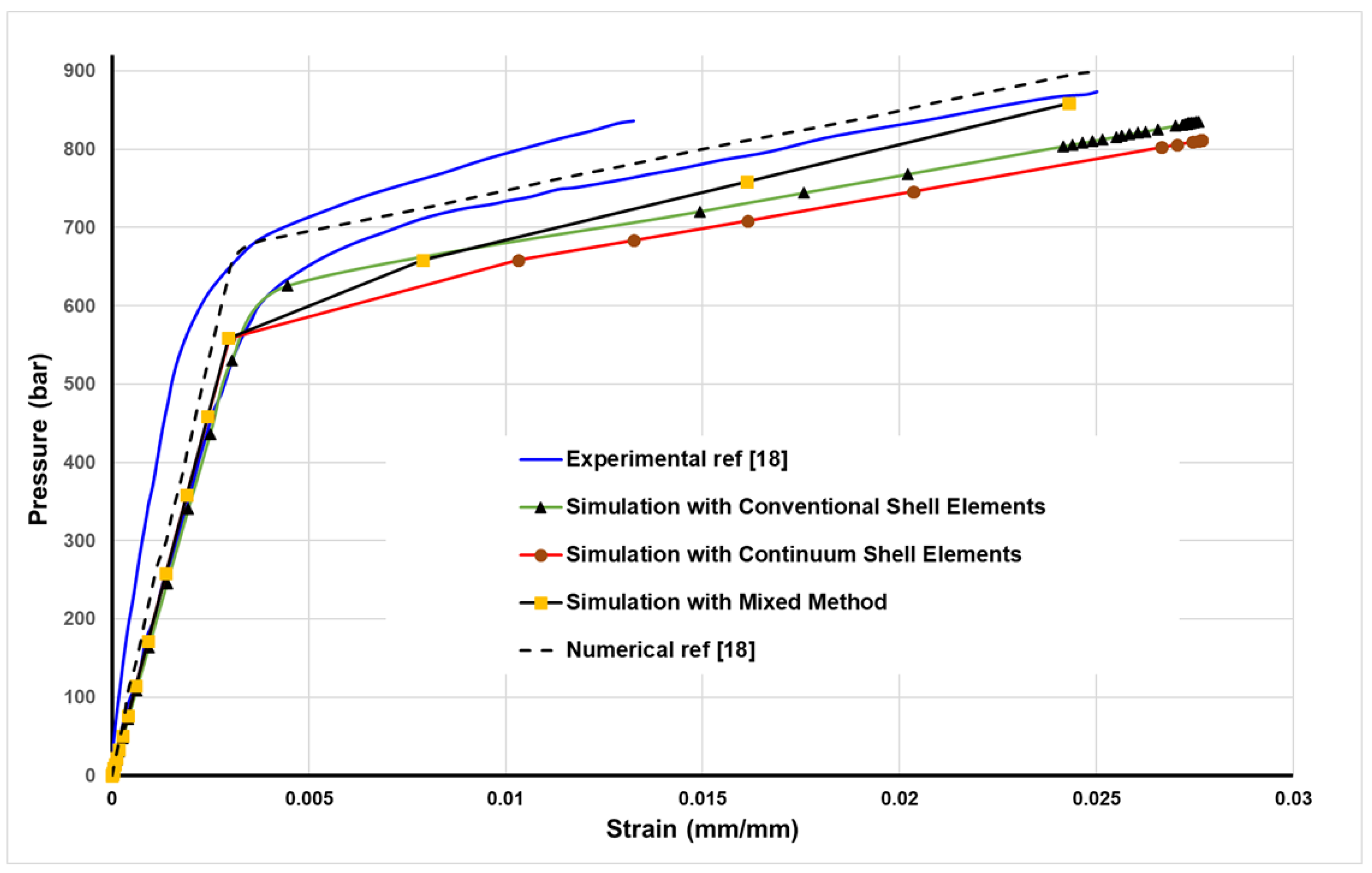
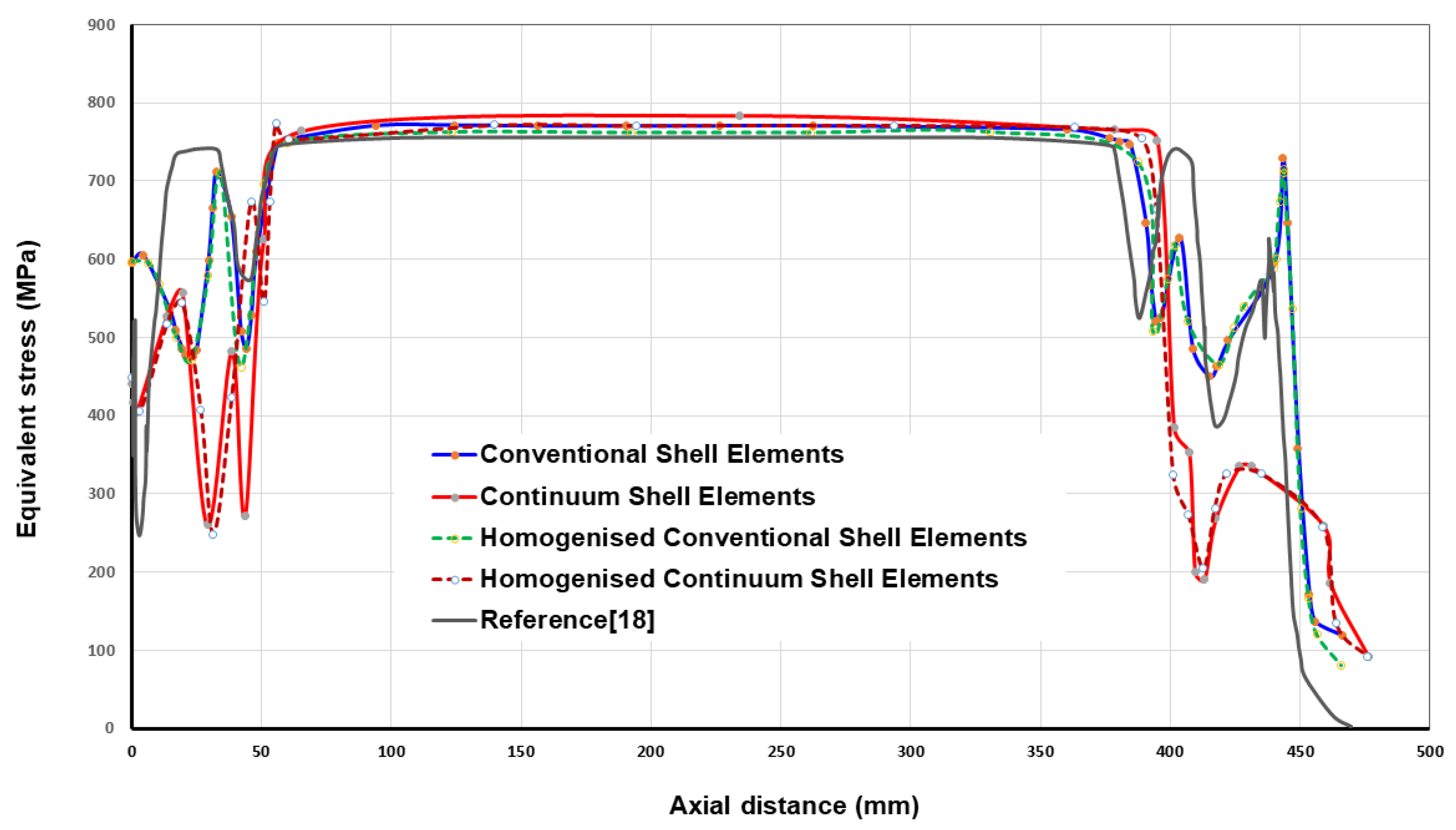
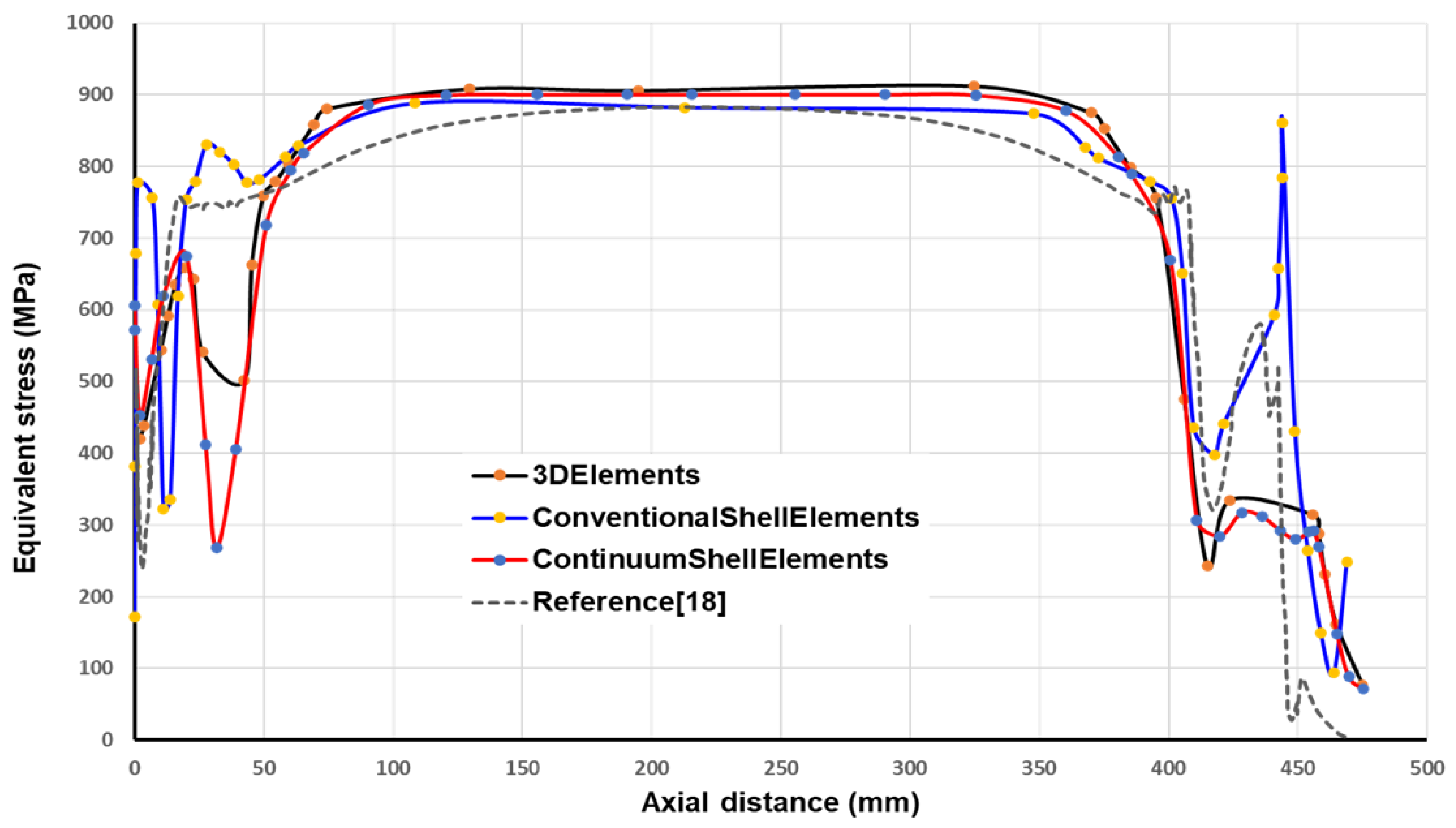
4. Comparison between Methods and Discussion

We here explore the mechanical behavior of a cylindrical tank subjected to internal pressure through a comparative analysis of experimental and numerical simulations. Reference [18] is utilized for benchmarking purposes. The tank’s response, in terms of hoop strain versus applied internal pressure at the central cylindrical section, is investigated using a combination of experimental and numerical techniques (see Figure 5).
The numerical simulations reveal that our methods tend to underestimate the global stiffness of the tank, leading to an earlier onset of yield compared with experimental results. This discrepancy is attributed to the absence of filament-wound composite interlacement in our simulations as it is well known that the interlacement of the filament bands increases the stiffness of the wound composite. However, the postyield behavior closely aligns across all curves, indicating successful modeling of the damage phenomenon. Notably, the mixed method deviates from this trend as it does not consider damage in the homogenization process. Among the numerical approaches, the one closest to experimental results employs conventional shell elements in Abaqus, which models the tank as a multilayer body, accounting for both liner and composite shell components. In contrast, the continuum shell element approach divides the tank into two distinct parts: liner and composite shell joined by tie contacts. Using the first experimental curve as a baseline, at a strain of 2.5%, the relative errors were approximately −6.28%, −10.85%, −0.57%, and +4% for the conventional shell element, continuum shell element, mixed, and reference numerical methods, respectively.
In this section, the tank’s response in terms of axial strains versus applied internal pressure is investigated at the central cylindrical section (see Figure 6). Again, our methods tend to underestimate the global stiffness of the tank, leading to an earlier onset of yield compared with experimental results. This is due to the absence of filament-wound composite interlacement, as mentioned before. However, our methods’ postyield behavior closely aligns with the experimental results, indicating successful modeling of the damage phenomenon. Notably, the mixed method and the conventional shell element methods are the closest. It bears emphasizing that the axial strains obtained with our methods are more accurate than those obtained by FEM in the reference. Using one experimental curve as a baseline, at a strain of 0.26%, the relative errors were approximately −1.84%, −7.97%, −1.22%, and +10.42% for the conventional shell element, continuum shell element, mixed, and reference numerical methods, respectively.
This comparative study sheds light on the accuracy and limitations of different simulation methods in predicting the mechanical response of composite cylindrical tanks under internal pressure.
Figure 7 presents a comparative analysis of equivalent stress profiles along the inner surface of a bare liner subjected to a pressure of 700 bars. The comparison is made between results obtained using our simulation methods and those from the numerical approach mentioned in the reference. Our method consistently yields higher equivalent stress values than the reference throughout the cylindrical section of the tank. However, all four curves closely align in this region. Notably, significant differences emerge in the dome regions, with distinct trends observed for all methods, although the continuum shell element and 3D element methods exhibit similarity. This divergence can be attributed to the accurate representation of varying dome thicknesses by the 3D element and continuum shell element methods, in contrast with the conventional element method, which assumes a constant dome thickness. Moreover, the front dome experiences more pronounced equivalent stress fluctuations compared with the rear dome, where the conventional shell elements display an exaggerated response due to the constant thickness assumption. This analysis highlights the influence of numerical methods on equivalent stress predictions in the diverse regions of cylindrical tanks, emphasizing the importance of accurately modeling varying thickness profiles, particularly in the dome sections.
Figure 8 presents a comparative analysis of equivalent stress distributions along the inner surface of the wound liner at 700 bars, employing our developed methods and the numerical approach introduced for comparison. The results reveal striking similarities between our methods and the reference in the cylindrical section of the tank, indicating that the wound liner experiences lower stress levels compared with a bare liner in this region. However, notable disparities emerge in the dome region between all the methods used, displaying a distinct response. Notably, our mixed method incorporating homogenization closely aligns with the method without homogenization, suggesting that homogenization plays a significant role in achieving accurate results. This consistency is observed in both the conventional shell element and continuum shell element analyses, affirming the precision of our homogenization approach. Furthermore, our methods offer enhanced insights into the dome region, surpassing the level of detail provided by the reference approach. The stress trends within the dome regions differ substantially across all methods, with the continuum shell element and mixed homogenized continuum shell element methods standing out as superior choices based on the previously mentioned reasons. It is worth noting that stress fluctuations are more pronounced in the front dome compared with the rear dome, mirroring the behavior observed in the bare liner. In summary, our study showcases the effectiveness of our methods in analyzing the stress distribution along a wound liner at high pressure, particularly in the dome region, where they offer enhanced insights and accuracy.

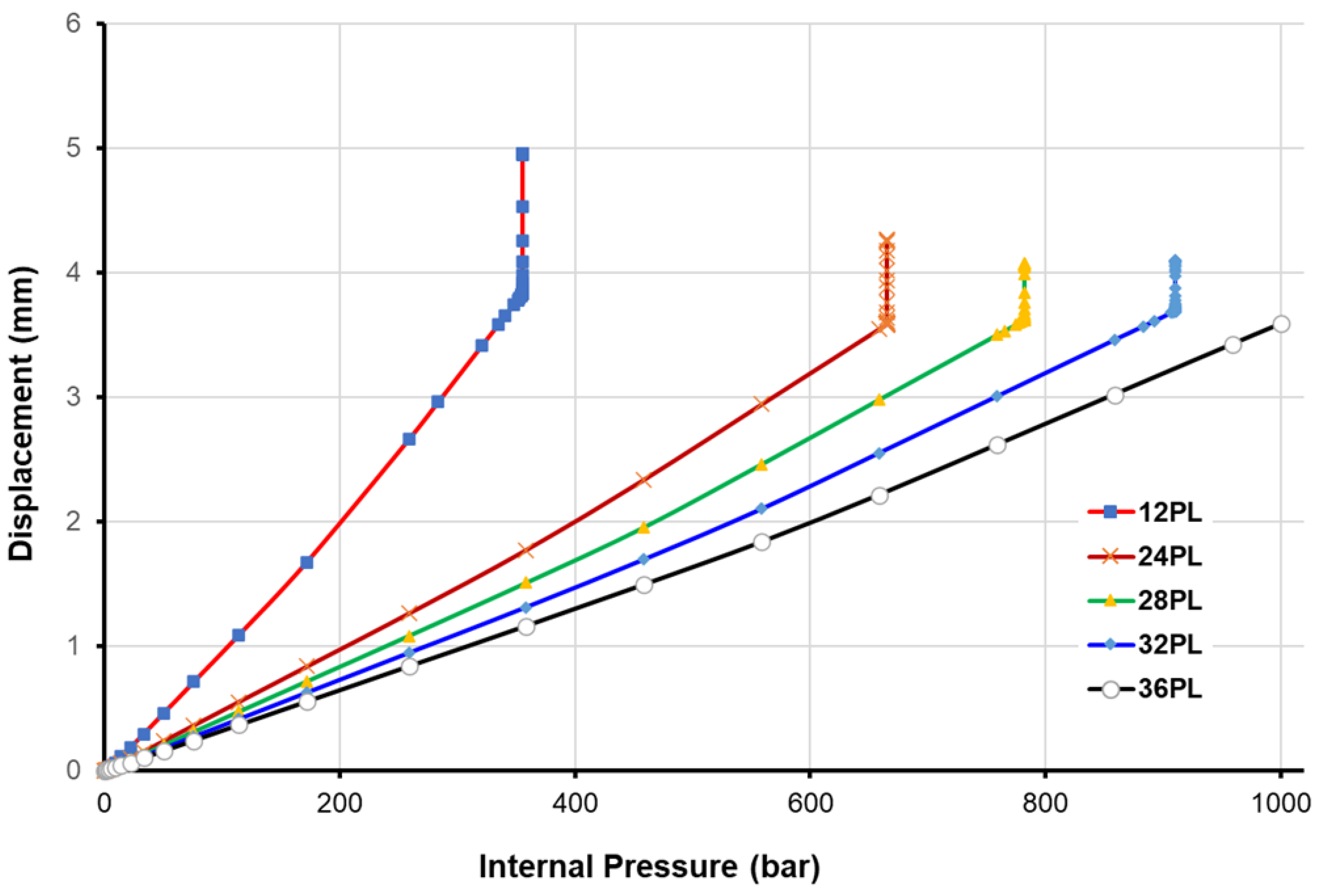
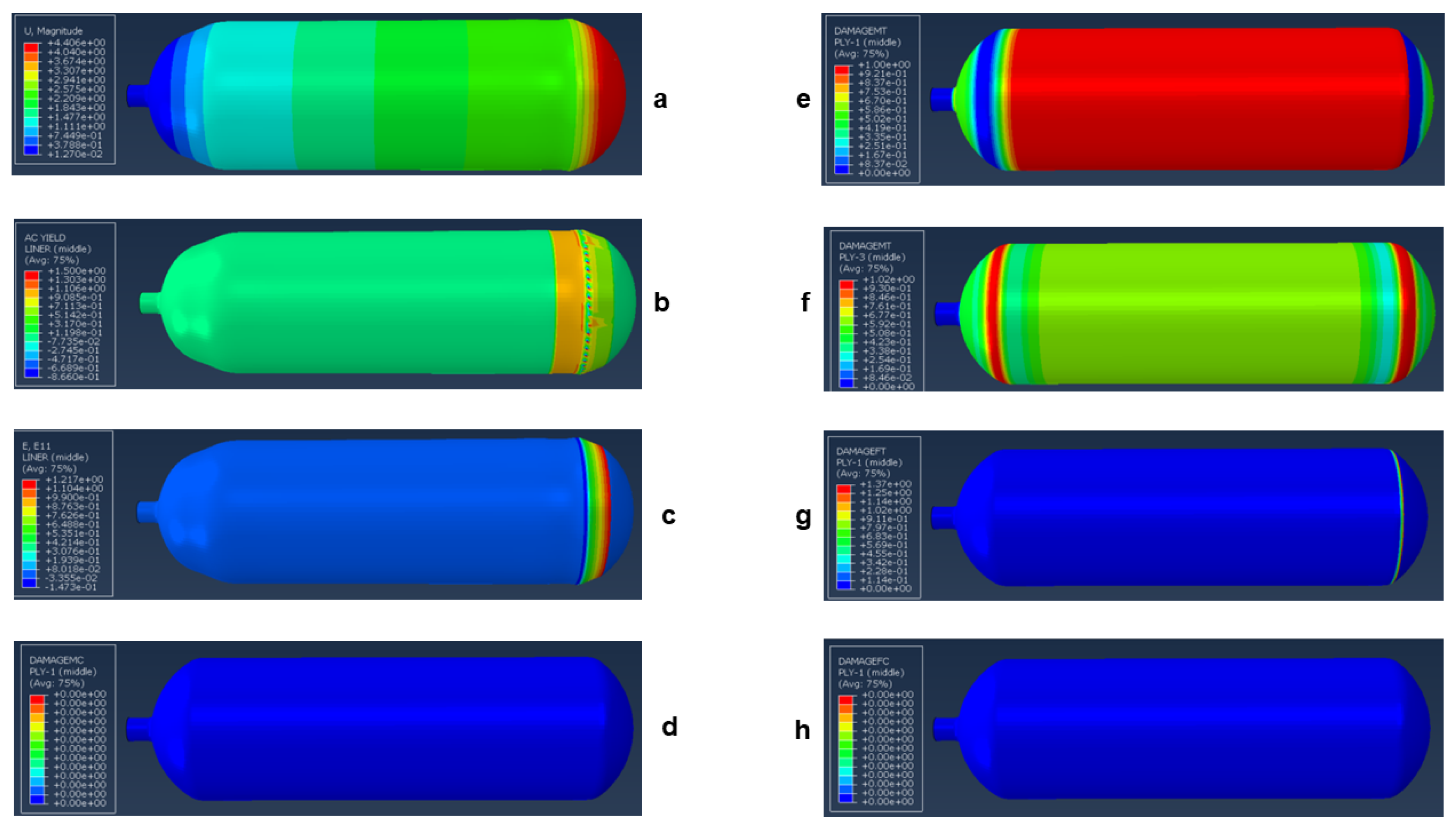
5. New Design of Type-IV Hydrogen Tank

Type-IV vessels represent a significant innovation in this context, constructed entirely from composite reinforcement polymer and featuring a plastic internal liner. However, their status as the lightest option renders them susceptible to damage scenarios, as the plastic liner does not contribute to load-bearing capacity. Among the various challenges associated with type-IV composite pressure vessels, the most critical one is the potential for burst due to laminate failure. Consequently, numerous research endeavors have been initiated to investigate burst pressure behavior and optimize vessel designs [34]. This section aims to extend our understanding by delving into the influence of laminated stacking sequence, orientation angle, and number of plies on burst pressure performance in type-IV composite pressure vessels.
Therefore, we propose the utilization of new materials, specifically high-density polyethylene (HDPE), for the liner and carbon-fiber-reinforced epoxy for the composite wound shell. HDPE serves as a preferred liner for Type-VI hydrogen tanks due to its beneficial characteristics. Recognized for its exceptional chemical resistance, it plays a vital role in safeguarding against potential leaks and maintaining the tank’s overall integrity when handling hydrogen gas. H2 is a molecule known for its small size and high permeability. Furthermore, HDPE stands out for its lightweight composition, durability, and minimal moisture absorption, rendering it well suited for scenarios where managing weight and moisture levels is crucial. Specifically designed to be lightweight and featuring a composite structure with a nonmetallic liner, type-VI hydrogen tanks prove to be highly adaptable for diverse transportation and storage needs. All the necessary property parameters for conducting simulations can be found in Table 3.
In the new tank design, we have maintained the same geometry and stacking arrangement as in the previous comparative study. The critical consideration at this juncture pertains to determining the number of plies required in the new design to withstand a pressure of 1000 bar without experiencing a burst. As tank pressure increases, it can burst either in a safe manner at the cylindrical part or in an unsafe manner at the domes. A safe burst occurs in the cylindrical section without posing any risk. Conversely, an unsafe burst occurs in the dome region, potentially leading to the ejection of the boss as a hazardous projectile. For the purpose of design optimization, the bursting mode serves as a critical constraint. The burst pressure is determined by identifying the load increment just before the radial and/or axial displacements start to diverge. A safe burst occurs when the radial displacement continues to increase under constant pressure at the cylindrical part of the tank, while an unsafe burst happens when the axial displacement increases at the dome extremity under constant pressure.
All of these phenomena eventually lead to simulation divergence, which halts the calculation process. It is important to emphasize that the mesh density utilized here allows for obtaining mesh-independent results. Initially, we maintained the same stacking configuration and number of plies as before (12 plies) to model the pressure at which the new design would burst. In Figure 9, we can observe the displacement response as a function of internal pressure at the dome extremity for each number of stacking plies. One can notice from the graph that the tank can withstand only 355 bar when we maintain the number of 12 plies (constant pressure with increasing displacement). We applied this criterion with varying numbers of plies, and whenever this divergence occurred (criterion is satisfied), we increased the layup by an additional 4 plies ( ± 11 , 90 2 ) and launched a new simulation. Figure 9 illustrates how the burst pressure is shifted with different stacking configurations until we achieve a condition where no divergence occurs. Consequently, we can assert that the tank can endure a pressure of 1000 bar when using 36 plies, resulting in a composite shell thickness of 7.2 mm. It is noteworthy that the burst occurs every time in the dome (unsafe mode).
Figure 10 depicts the tank behavior and the damage response based on the Hashin criterion in both the fiber and the matrix for a composite shell of 24 plies; the results are taken mainly at the liner, at the first ply (orientation 11) and the third ply (orientation 90).
Finally, by maintaining the same number of 36 plies but altering the filament angle to ( ± 55 )18, we found that the tank can only withstand a maximum of 140 bar. This highlights the significance of stacking sequence and pattern as key parameters influencing the tank’s burst pressure, emphasizing the need for optimization techniques to enhance the tank’s performance.

6. Concluding Remarks

  • In this study, we presented a comparative analysis of various numerical methods for modeling composite pressure vessels, aiming to provide a comprehensive understanding of their performance. The methods under scrutiny include finite element analysis in Abaqus with conventional shell element, continuum shell element, three-dimensional solid element, and homogenization approaches for multilayered composite pressure vessels. Through a systematic comparison, this research offers insights into the strengths and limitations of each method. It is crucial to emphasize that the results achieved could be replicated with a lower mesh density when utilizing only a quarter of the model.
  • The findings of this study indicate that three-dimensional solid elements yield the highest accuracy in modeling composite pressure vessels. However, their practicality diminishes as the number of layers in the composite increases. Following closely are the continuum shell elements, which strike a balance between accuracy and computational efficiency due to their intermediate nature, combining features of both 3D and conventional shell elements. Meanwhile, the method relying solely on conventional shell elements proves to be accurate for specific applications but lacks universality.
  • Moreover, this research underscores the significance of the homogenization technique used in the mixed method as an alternative, particularly for damage-free applications, as it consistently delivers highly accurate results. The approach involves treating the composite shell section of the tank as a straightforward homogenized layer.
  • A new design dedicated to a type-IV hydrogen tank, composed of carbon fibers, epoxy resin, and a high-density polyethylene (HDPE) liner, is proposed. The study concentrates on predicting damage onset and behavior within the tank and burst pressure prediction. With this new design, we demonstrated that the tank can endure a pressure of 1000 bar when using 36 plies, resulting in a composite shell thickness of 7.2 mm. Undoubtedly, future optimization is essential as this exploration aligns with the broader scope of a significant project where we are concurrently working on new materials development.

Author Contributions

L.B.: conceptualization, methodology, software development, investigation, writing—original draft preparation, project acquisition, and administration. Y.K.: conceptualization, methodology, investigation, and writing—original draft preparation. A.K.: writing—reviewing and editing. C.B.: reviewing and editing. All authors have read and agreed to the published version of the manuscript.

Funding

This research was funded in whole, or in part, by the Luxembourg National Research Fund (FNR), grant reference [«INTER/MERA22/17557282/HYMOCA»]. For the purpose of open access, the author has applied for a Creative Commons Attribution 4.0 International (CC BY 4.0) license to any author-accepted manuscript version arising from this submission.

Data Availability Statement

The raw/processed data required to reproduce these findings cannot be shared at this time as the data also form part of an ongoing study.

Acknowledgments

The authors would also like to express their gratitude for the support received from the Sustainable Composite Materials and Manufacturing (SCMM) Innovation Centre.

Conflicts of Interest

The authors declare that they have no known competing financial interests or personal relationships that could have appeared to influence the work reported in this paper.

References

  1. Xu, P.; Xu, P.; Zheng, J.; Liu, P. Finite element analysis of burst pressure of composite hydrogen storage vessels. Mater. Des. 2009, 30, 2295–2301. [Google Scholar] [CrossRef]
  2. Rafiee, R.; Torabi, M.A. Stochastic prediction of burst pressure in composite pressure vessels. Compos. Struct. 2018, 185, 573–583. [Google Scholar] [CrossRef]
  3. Zheng, J.; Liu, P. Elasto-plastic stress analysis and burst strength evaluation of al-carbon fiber/epoxy composite cylindrical laminates. Comput. Mater. Sci. 2008, 42, 453–461. [Google Scholar] [CrossRef]
  4. Liu, P.; Zheng, J. Progressive failure analysis of carbon fiber/epoxy composite laminates using continuum damage mechanics. Mater. Sci. Eng. -Struct. Mater. Prop. Microstruct. Process. 2008, 485, 711–717. [Google Scholar] [CrossRef]
  5. Liu, P.; Liu, P.; Chu, J.; Chu, J.; Chu, J.; Hou, S.; Xu, P.; Xu, P.; Xu, P.; Zheng, J. Numerical simulation and optimal design for composite high-pressure hydrogen storage vessel: A review. Renew. Sustain. Energy Rev. 2012, 16, 1817–1827. [Google Scholar] [CrossRef]
  6. Ramirez, J.P.B.; Halm, D.; Grandidier, J.-C.; Villalonga, S.; Villalonga, S. A fixed directions damage model for composite materials dedicated to hyperbaric type iv hydrogen storage vessel—Part I: Model formulation and identification. Int. J. Hydrogen Energy 2015, 40, 13165–13173. [Google Scholar] [CrossRef]
  7. Humberto, J.; Almeida, J.; St-Pierre, L.; Wang, Z.; Ribeiro, M.L.; Tita, V.; Amico, S.C.; Castro, S.G. Design, modelling, optimization, manufacturing, and testing of variable-angle filament-wound cylinders. Compos. Part 2021, 225, 109224. [Google Scholar]
  8. Zhanga, Q.; Xua, H.; Jiab, X.; Zua, L.; Chenga, S.; Wanga, H. Design of a 70 mpa type iv hydrogen storage vessel using accurate modelling techniques for dome thickness prediction. Compos. Struct. 2020, 236, 111915. [Google Scholar] [CrossRef]
  9. Jois, K.C.; Welsh, M.; Gries, T.; Sackmann, J. Numerical analysis of filament wound cylindrical composite pressure vessels accounting for variable dome contour. J. Compos. Sci. 2021, 5, 56. [Google Scholar] [CrossRef]
  10. Zhang, N.; Gao, S.; Song, M.; Chen, Y.; Zhao, X.; Liang, J.; Feng, J. A multiscale study of cfrp based on asymptotic homogenization with application to mechanical analysis of composite pressure vessels. Polymers 2022, 14, 2817. [Google Scholar] [CrossRef]
  11. Kang, H.; He, P.; Zhang, C.; Dai, Y.; Lv, H.; Zhang, M.; Yang, D. Stress–strain and burst failure analysis of fibre wound composite material high-pressure vessel. Polym. Polym. Compos. 2021, 29, 1291–1303. [Google Scholar] [CrossRef]
  12. Landi, A.V.D.; Borriello, S.; Scafà, M.; Germani, M. A methodological approach for the design of composite tanks produced by filament winding. Comput.-Aided Des. Appl. 2020, 17, 1229–1240. [Google Scholar] [CrossRef]
  13. Jebeli, M.A.; Heidari-Rarani, M. Development of abaqus wcm plugin for progressive failure analysis of type iv composite pressure vessels based on puck failure criterion. Eng. Fail. Anal. 2022, 131, 105851. [Google Scholar] [CrossRef]
  14. Wang, H.; Fu, S.; Chen, Y.; Hua, L. Thickness-prediction method involving tow redistribution for the dome of composite hydrogen storage vessels. Polymers 2021, 14, 902. [Google Scholar] [CrossRef] [PubMed]
  15. Zhang, M.; Lv, H.; Kang, H.; Zhou, W.; Zhang, C. A literature review of failure prediction and analysis methods for composite high-pressure hydrogen storage tanks. Int. J. Hydrogen Energy 2019, 44, 25777–25799. [Google Scholar] [CrossRef]
  16. Kartav, O.; Kangal, S.; Yücetürk, K.; Tanoglu, M.; Aktas, E.; Artem, H.S. Development and analysis of composite overwrapped pressure vessels for hydrogen storage. J. Compos. Mater. 2021, 55, 002199832110335. [Google Scholar] [CrossRef]
  17. Regassa, Y.; Gari, J.; Lemu, H.G. Composite overwrapped pressure vessel design optimization using numerical method. J. Compos. Sci. 2022, 6, 229. [Google Scholar] [CrossRef]
  18. Kangal, S.; Kartav, O.; Tanoglu, M.; Aktas, E.; Artem, H.S. Investigation of interlayer hybridization effect on burst pressure performance of composite overwrapped pressure vessels with load-sharing metallic liner. J. Compos. Mater. 2020, 54, 961–980. [Google Scholar] [CrossRef]
  19. Nguyen, B.N.; Roh, H.S.; Merkel, D.R.; Simmons, K.L. A predictive modelling tool for damage analysis and design of hydrogen storage composite pressure vessels. Int. J. Hydrogen Energy 2021, 46, 20573–20585. [Google Scholar] [CrossRef]
  20. Moradi, R.; Growth, K.M. Hydrogen storage and delivery: Review of the state-of-the-art technologies and risk and reliability analysis. Int. J. Hydrogen Energy 2019, 44, 12254–12269. [Google Scholar] [CrossRef]
  21. Modesto, A.J.; Birgul, R.; Werlink, R.J.; Catbas, F.N. Damage detection of composite overwrapped pressure vessels using arx models. Int. J. Press. Vessel. Pip. 2021, 192, 104410. [Google Scholar] [CrossRef]
  22. Guo, L.W.K.; Xiao, J.; Lei, M.; Wang, S.; Zhang, C.; Hou, X. Design of winding pattern of filament wound composite pressure vessel with unequal openings based on non-geodesics. J. Eng. Fibers Fabr. 2020, 15, 1–17. [Google Scholar] [CrossRef]
  23. Air, A.; Oromiehie, E.; Prusty, G. Design and manufacture of a type v composite pressure vessel using automated fibre placement. Compos. Part Eng. 2023, 266, 111027. [Google Scholar] [CrossRef]
  24. Belardi, V.; Ottaviano, M.; Vivio, F. Bending theory of composite pressure vessels: A closed-form analytical approach. Compos. Struct. 2024, 329, 117799. [Google Scholar] [CrossRef]
  25. Lin, J.; Zheng, C.; Dai, Y.; Wang, Z.; Lu, J. Prediction of composite pressure vessel dome contour and strength analysis based on a new fiber thickness calculation method. Compos. Struct. 2023, 306, 116590. [Google Scholar] [CrossRef]
  26. Rohatgi, A. Webplotdigitizer: Version 4.6. 2022. Available online: https://automeris.io/WebPlotDigitizer (accessed on 2 January 2024).
  27. Bouhala, L.; Makradi, A.; Belouettar, S.; Kiefer-Kamal, H.; Fréres, P. Modelling of failure in long fibres reinforced composites by xfem and cohesive zone model. Compos. Part B 2013, 55, 352–361. [Google Scholar] [CrossRef]
  28. Bouhala, L.; Shao, Q.; Koutsawa, Y.; Younes, A.; Núnez, P.; Makradi, A.; Belouettar, S. An xfem crack-tip enrichment for a crack terminating at a bi-material interface. Eng. Fract. Mech. 2013, 102, 51–64. [Google Scholar] [CrossRef]
  29. Dassault Systèmes. Micromechanics Plugin for Abaqus/CAE, Version 1.18; Dassault Systèmes Simulia Corp.: Providence, RI, USA, 2022. [Google Scholar]
  30. Azoti, W.L.; Tchalla, A.; Koutsawa, Y.; Makradi, A.; Rauchs, G.; Belouettar, S.; Zahrouni, H. Mean-field constitutive modeling of elasto-plastic composites using two (2) incremental formulations. Compos. Struct. 2013, 105, 256–262. [Google Scholar] [CrossRef]
  31. Bouhala, L.; Koutsawa, Y.; Makradi, A.; Belouettar, S. An advanced numerical method for predicting effective elastic properties of heterogeneous composite materials. Compos. Struct. 2014, 117, 114–123. [Google Scholar] [CrossRef]
  32. Dassault Systèmes. User’s Manual; Version 2022; Dassault Systèmes Simulia Corp.: Providence, RI, USA, 2022. [Google Scholar]
  33. Lapczyk, I.; Hurtado, J.A. Progressive damage modeling in fiber-reinforced materials. Compos. Part A Appl. Sci. Manuf. 2007, 38, 2333–2341. [Google Scholar] [CrossRef]
  34. Sapre, S.; Pareek, K.; Vyas, M. Investigation of structural stability of type iv compressed hydrogen storage tank during refueling of fuel cell vehicle. Energy Storage 2020, 2, 150. [Google Scholar] [CrossRef]
Figure 1. Geometry of the bare liner used for comparison from reference [18].
Jcs 08 00040 g001
Figure 2. Abaqus conventional shell element composite layup feature overview.
Jcs 08 00040 g002
Figure 3. Abaqus continuum shell element composite layup feature overview.
Jcs 08 00040 g003
Figure 4. Abaqus model for both solid-to-solid and solid-to-shell homogenization scenarios.
Jcs 08 00040 g004
Figure 5. Comparison Between the hoop strain and the applied internal pressure obtained with the conventional shell element, continuum shell element, and mixed method and the experimental and numerical results of the reference.
Jcs 08 00040 g005
Figure 6. Comparison between the axial strain and the applied internal pressure obtained with the conventional shell element, continuum shell element, and mixed methods and the experimental and numerical results of the reference.
Jcs 08 00040 g006
Figure 7. Comparison Equivalent stress vs. axial distance along the inner surface of the bare liner at 700 bar using conventional shell elements, continuum shell elements, and 3D elements.
Jcs 08 00040 g007
Figure 8. The Equivalent stress vs. axial distance along the inner surface of the wound liner at 700 bar using conventional shell elements, continuum shell elements, homogenized conventional shell elements, and homogenized continuum shell elements.
Jcs 08 00040 g008
Figure 9. The axial displacement at the extremity of the back dome vs. the internal pressure for different numbers of plies using the conventional shell element model.
Jcs 08 00040 g009
Figure 10. Response simulation using the conventional shell element model at failure for a stacking of 24 plies: (a) magnitude of the displacement, (b) yield response in the polymeric liner, (c) axial strain in the liner, (d) compression damage of the matrix in the first ply, (e) tensile damage of the matrix in the first ply, (f) damage of the matrix in tension at the third ply, (g) damage of the fiber in tension at the first ply, and (h) damage of the fiber in compression at the first ply.
Jcs 08 00040 g010
Table 1. Elastic properties and stress limits of glass-fiber-reinforced epoxy-based composites and elastic-plastic properties of the steel liner.
SymbolDescriptionUnitValue
Glass fiber/epoxy composite
E 1 Longitudinal (fiber-dominated) modulusMPa38,500
E 2 = E 3 Transverse (matrix-dominated) modulusMPa16,500
ν 12 Poisson’s ratio (in-plane)-0.27
ν 23 Poisson’s ratio (planes 2–3)-0.28
G 12 = G 13 In-plane shear modulusMPa4700
G 23 Shear modulus (planes 2–3)MPa5000
X T Longitudinal (fiber-dominated) tensile strengthMPa1250
X C Longitudinal (fiber-dominated) compressive strengthMPa−650
Y T Transverse (matrix-dominated) tensile strengthMPa36
Y C Transverse (matrix-dominated) compressive strengthMPa−165
S L In-plane shear strengthMPa86
G f Fracture energy of the fiberN/mm12.5
G m Fracture energy of the matrixN/mm1
Steel liner (SL)
E SL Young’s modulusMPa205,000
ν SL Poisson’s ratio-0.3
σ y , SL Yield strengthMPa743
E tan , SL Bilinear isotropic hardening tangent modulusMPa2600
Table 2. Three-dimensional effective properties corresponding to the solid-to-solid homogenization scenario.
E 1 (MPa) E 2 (MPa) E 3 (MPa) ν 12 (-) ν 13 (-) ν 23 (-) G 12 (MPa) G 13 (MPa) G 23 (MPa)
26,548.2427,347.3417,343.400.1800.3440.3395204.7747004700
Table 3. Elastic properties and stress limits of carbon-fiber-reinforced epoxy-based composites and elastic-plastic properties of the high-density polyethylene (HDPE) liner [18,32].
SymbolDescriptionUnitValue
Carbon fiber/epoxy composite
E 1 Longitudinal (fiber-dominated) modulusMPa141,000
E 2 = E 3 Transverse (matrix-dominated) modulusMPa11,400
ν 12 Poisson’s ratio (in-plane)-0.28
ν 23 Poisson’s ratio (planes 2–3)-0.40
G 12 = G 13 In-plane shear modulusMPa5000
G 23 Shear modulus (planes 2–3)MPa3080
X T Longitudinal (fiber-dominated) tensile strengthMPa2080
X C Longitudinal (fiber-dominated) compressive strengthMPa−1250
Y T Transverse (matrix-dominated) tensile strengthMPa60
Y C Transverse (matrix-dominated) compressive strengthMPa−290
S L In-plane shear strengthMPa110
G f Fracture energy of the fiberN/mm78
G m Fracture energy of the matrixN/mm1
Isotropic elastic properties for the high-density polyethylene liner (HDPE) [32]
E HDPE Young’s modulusMPa903.114
ν HDPE Poisson’s ratio-0.39
Isotropic plastic hardening data for the HDPE liner material [32]
Yield stress (MPa)8.61813.06416.78718.47620.33724.54326.887
Plastic strain (-)00.0070.0250.0440.0810.280.59
Disclaimer/Publisher’s Note: The statements, opinions and data contained in all publications are solely those of the individual author(s) and contributor(s) and not of MDPI and/or the editor(s). MDPI and/or the editor(s) disclaim responsibility for any injury to people or property resulting from any ideas, methods, instructions or products referred to in the content.

