Article

Influence of Grinding Tool Mesh Size and Rotational Speed on Post-Machining Quality of CFRP Laminates by Acceleration Signal and Surface Roughness Analyses

by
Lichen Li
1,
Ziyuan Song
2,
Xinxin Zhang
2,
Fangyuan Wang
1,
Pengda Song
1,
Kai Jin
1,*,
Taeyong Lee
3 and
Luca Quagliato
3,*
1
College of Material Science and Technology, Ocean University of China, Qingdao 266100, China
2
Hisense (Shandong) Refrigerator Co., Ltd., Qingdao 266100, China
3
Department of Mechanical and Biomedical Engineering, Ewha Womans University, Seoul 03760, Republic of Korea
*
Authors to whom correspondence should be addressed.
J. Compos. Sci. 2024, 8(12), 543; https://doi.org/10.3390/jcs8120543
Submission received: 6 November 2024 / Revised: 30 November 2024 / Accepted: 12 December 2024 / Published: 20 December 2024
(This article belongs to the Special Issue Carbon Fiber Composites, Volume III)

Abstract

:
In the grinding process, acceleration signals in both the time and frequency domains are valuable for monitoring and controlling vibration patterns, as factors such as rotational speed and the grinding head design significantly influence machining quality, efficiency, and finishing performance. This study analyzes the acceleration signals by dividing them into three distinct stages, pairing this analysis with microscopic morphology to investigate the grinding behavior of carbon fiber-reinforced polymer (CFRP). The findings reveal that high-frequency and low-amplitude vibrations enhance polishing efficiency and quality, whereas low-frequency and high amplitudes adversely affect grinding quality. Acceleration vibrations are more stable during the intermediate grinding stage compared to the initial and final stages, which helps reduce surface roughness, regardless of the rotational speed or grinding head mesh size. In addition, a coarse mesh (#40) results in an uneven surface due to a large amount of removed material, whereas a fine one (#120) results in lower material removal but continuous vertical vibrations due to the impact with the grinding surface, also resulting in poor surface quality. Thus, controlling the tool’s size and rotational speed is essential in reducing the amplitude of the vibration, allowing for maximizing the grinded CFRP surface quality.

1. Introduction

The increasing variety of carbon fiber-reinforced polymers (CFRPs) has significantly driven the expansion of these materials across multiple fields [1,2]. Traditional CFRP composite manufacturing methods, such as hot press molding and injection molding, have been commonly used. However, the slow processing times or the high costs associated with these methods are now insufficient to meet the evolving needs of modern industries [3,4,5]. Consequently, additional manufacturing technologies are being explored, leveraging well-established processes from metallic materials, such as grinding, milling, drilling, and turning [6,7]. While practical and widely available in many industrial settings, these conventional machining methods are influenced by various factors, including grinding wheel speed, grit size, feed rate, and lubrication conditions. In response, recent research has begun to explore the interactions between these relatively traditional techniques when applied to the processing of CFRPs. For instance, Wang et al. [8] found that high grinding speeds enhance the surface quality of CFRP, especially when combined with industrial robots. Their study demonstrated that a grit size of #80 achieved the best grinding results and highest surface quality. Similarly, Liu et al. [9] applied the Box–Behnken design and response surface methodology (RSM) to analyze the effects of spindle speed, cutting depth, feed rate, and grit size on grinding force and surface roughness, ultimately developing an optimization model to identify the ideal process parameters. Subsequent research has corroborated that grinding force is directly proportional to cutting depth and feed rate but inversely proportional to grinding wheel speed [10,11,12], showing insights into improving processing quality by selecting optimal grinding parameters.
Beyond process parameters, the choice and specifications of tools have a considerable impact on machining quality. This has led researchers to focus on tool design specifically for CFRP grinding. For instance, Nomura et al. [13] addressed the limitations of conventional grinding wheels for CFRP by developing a new type of wheel with diamond abrasive grains electrochemically deposited on a circular metal wire mesh. This innovation effectively prevents clogging during grinding and enhances surface quality. Additionally, Xu et al. [14] found that diamond-coated tools can significantly lower drilling temperatures, reducing the risk of localized glass transition within the composite matrix and thus preventing degradation of mechanical performance. Based on the tool design proposed by Nomura et al. [13], Liang et al. [15] conducted research using a robotic arm equipped with small-volume brazed diamond abrasive heads for ultrasonic-assisted grinding of CFRP. Their study established a mathematical model for grinding force to determine the optimal spacing between abrasive grains, aiming to improve both grinding outcomes and surface quality. They also demonstrated that using a robotic arm to handle the diamond grinding head offers significant advantages in processing small, intricate workpieces.
In addition to diamond abrasives, researchers have explored other abrasive particles to assess grinding quality. Soo et al. [16] investigated the performance of diamond and cubic boron nitride (CBN) abrasives on CFRP. Their study found that CBN tools experienced greater wear, cutting force, and surface roughness compared to diamond grinding heads, providing important guidance for selecting appropriate machining tools. Wang et al. [17] examined five different drill bits with ultrasonic assistance for CFRP grinding. They experimentally analyzed tool variables such as abrasive size, abrasive concentration, groove count, and tool end geometry on machining performance. Their findings showed that larger abrasive sizes, lower abrasive concentrations, and tools with two grooves reduced cutting force and torque, while smaller abrasive sizes and lower abrasive concentrations in tools with two grooves and convex end geometry produced better surface smoothness. Similarly, Tao et al. [18] developed an innovative discontinuous grinding head and studied its interactions with CFRP, creating a grinding force model for two types of discontinuous micro-grinding tools. Interest in developing new grinding tools for composite materials, particularly CFRP [19], as well as ceramic matrix composites [20,21], has surged over the past two years. These efforts continue to introduce novel grinding techniques and enhance the surface quality of manufactured components.
Recognizing the industrial trend toward robotic machining [22,23] and the need to account for the dynamic interaction between robotic movements and the machining forces involved [24], this study investigates the influence of the grinding wheel rotational speed and grit size on the acceleration signals during the grinding process of CFRP laminates, initially manufactured by hot pressing. Three head mesh sizes have also been included to establish a correlation between them and the mentioned grinding process parameters.
By analyzing the variations in vibration frequency and amplitude during the initial, middle, and final stages of the grinding process, this research examines the material removal mechanisms in CFRPs and their impact on surface quality. The results reveal that high surface quality can be achieved by increasing vibration frequency, while the number of grinding heads plays a crucial role in determining surface roughness.

2. Materials and Methods

2.1. CFRP Laminates’ Manufacturing

In the experiments, 0.14 mm/layer thick plain weave USN150 (SK-Chemical, Seongnam-si, Republic of Korea) prepregs were used to manufacture CFRP laminates through curing by hot pressing. The prepreg material was laminated and cured under a pressure of 2 MPa at 175 °C for 1.5 h. A summary of the properties is reported in Table 1. The manufactured specimens employed in the grinding process have dimensions of 200 mm (length), 20 mm (width), and 2 mm (thickness), respectively.

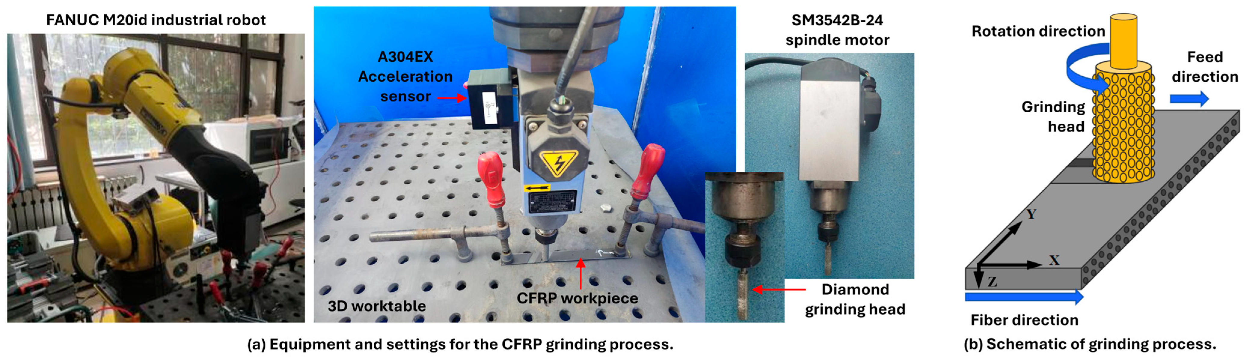
2.2. CFRP Grinding Process

For the grinding of the CFRP laminates, the tooling equipment shown in Figure 1a was employed and includes the FANUC M20id industrial robot (Rochester Hills, MI, USA), a 3D worktable, an A304EX accelerometer (Paeonian Springs, VA, USA), the SM3542B-24 spindle motor (Dongguan Tianyi Precision Electromechanical Co., Ltd., Guangzhou, China), and a diamond grinding head. The schematic diagram of the grinding process is shown in Figure 1b. A systematic study was conducted to study the relationship between the acceleration signal and grinding mechanism, considering the parameters’ levels shown in Table 2. The employed A304EX acceleration sensor, as shown in Figure 1a, is connected with the BeeData software (https://www.beetech.cn/products/147.html—Accessed date: 20 November 2023) employed to record, export, and post-process the acceleration signals during the experiments. The three employed grinding tools, named #40, #80, and #120, are representative of average particle sizes of 345 μm, 181 μm, and 110 μm, respectively, all with a grinding head diameter equal to 10 mm. The microscopic images of abrasive particles from different grinding head nets are shown in Figure 2, where three particles are measured as an example and are representative of the whole distribution throughout the grinding head.
For the case of the #40 grinding head, both the abrasive particle diameter and the gap between the particles are significantly larger compared to those of #80 and #120. Consequently, the gap between abrasive particles hinders the material removal capabilities and prevents them from achieving uniform grinding. In this scenario, certain areas undergo more intense cutting while others remain insufficiently affected, leading to an uneven surface height. As a final remark, all experiments involved the utilization of deionized water as a coolant during processing. Due to its effective heat dissipation capability and non-reactivity with the CFRP machined surface, deionized water is employed for cooling purposes.

3. Results and Discussion

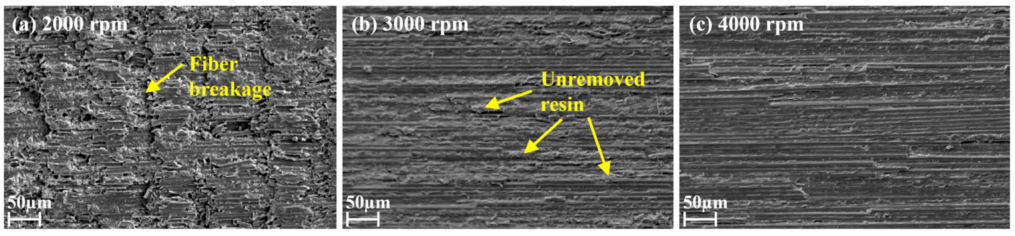
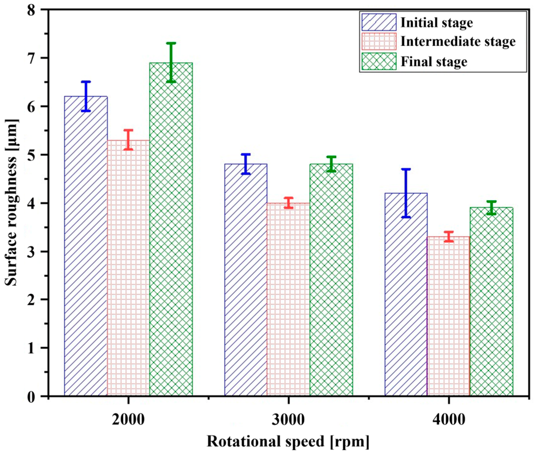
3.1. Relationship Between Speed and Acceleration Vibration Signals

The analysis presented in this section aims at showing the influence of the rotation speed of the spindle and the resulting surface quality of the grinded CFRP. To this end, only the #80 grit grinding head was considered, as it represents the intermediate mesh size. The Z-axis acceleration time domain and fast Fourier transformation (FFT) charts at grinding head rotating speeds of 2000 rpm, 3000 rpm, and 4000 rpm (#80, 0°) are shown in Figure 3. Here, “0°” refers to the angle between the fiber direction of the CFRP and the grinding feed direction.
When the rotation speed is 2000 rpm, the vibration frequencies generated during the grinding process are concentrated between 100 Hz and 300 Hz. When the rotational speed of the grinding tool increases (Figure 3a–c), both low-frequency and high-frequency vibrations occur during the grinding process, and the main forms of vibration are increasingly concentrated around 200 Hz. As shown in the FFT chart of Figure 3b, at 3000 rpm, there are low-frequency vibrations with a frequency of 43 Hz and an amplitude of 0.053 g, as well as high-frequency vibrations with a frequency of 389 Hz and an amplitude of 0.056 g. At 4000 rpm, there are low-frequency vibrations with a frequency of 25 Hz and an amplitude of 0.081 g, as well as high-frequency vibrations with a frequency of 398 Hz and an amplitude of 0.063 g.
As the speed increases, the interaction between the tool and the workpiece becomes more intense, resulting in a faster accumulation of grinding debris. High-frequency vibrations can quickly remove the debris, thereby improving the grinding efficiency and the quality of the debris. Moreover, after the debris is vibrated out, the grinding resistance instantly decreases, resulting in low-frequency vibrations. The smaller amplitude of high-frequency vibrations is due to their auxiliary role in debris removal compared to the main vibration mode (around 200 Hz) generated by the removal of CFRP material.
The grinding mechanism at different grinding speeds is illustrated in Figure 4, where the tilting of the tool is reported to highlight the high resistance encountered by the grinding head, especially for low rotational speeds of 2000 rpm (Figure 4a) and also slightly at 3000 rpm (Figure 4b). The misalignment in the z-direction is not intentionally inputted as a grinding angle ≠ 0 but is the result of the interaction between the coarse mesh size of the diamond grinding head and the CFRP workpiece.
As the grinding process progresses, the fibers at the interface with the grinding head experience pressure from the Z and X directions, causing them to bend and fracture slightly. In conjunction with the low-frequency vibration peak of 0.138 g generated at 91 Hz, as shown in Figure 3a, the vibration frequency of the grinding head is relatively slow. In this scenario, the grinding head continuously impacts the grinding surface at the edge of its bottom surface, creating a rippled grinding surface, as shown in Figure 5a, with fibers and resin remaining unremoved.
As the speed increases, the grinding resistance decreases, and the predominant vibration mode of grinding becomes more concentrated around 200 Hz. The appearance of high-frequency, low-amplitude vibration helps alleviate the resistance caused by the grinding debris, resulting in less tilt of the diamond grinding head and the generation of continuous, closely spaced impacts. The impact amplitude in the Z-axis direction is significantly reduced, thereby improving the grinding surface, as visible by comparing Figure 5a–c. By considering Figure 3 and Figure 5 together, for a spindle rotation speed of 3000 rpm, a significant amount of resin remains unremoved due to the grinding vibration frequency not being sufficiently concentrated.
Aiming for a deeper understanding of the reason for the variation in the surface quality shown in Figure 5, the FFT charts of the Z-axis acceleration at different speeds (#80, 0°) in the three stages of the grinding process are shown in Figure 6a–c. Figure 6 shows the acceleration peaks in the frequency domain on the left and, on the right, the confocal morphology and magnitude of surface roughness for the three speeds and the initial, intermediate, and final stages. In the same image, the post-grinding CFRP specimens are reported with the identification of the four points for each stage, employed for the measurement of the Sa roughness micrographs.
Moving from Figure 6a–c, the vibrations generated during grinding have larger amplitudes in the initial and final stages, while the amplitude decreases in the intermediate stage. Moreover, low- and high-frequency vibrations occur in all three stages of grinding with increasing speed, consistent with the frequency domain variations of the acceleration throughout the grinding process (Figure 3).
However, in the case of a 3000 rpm rotational speed for the grinding head (Figure 6b), it is found that a high-frequency vibration with a frequency of 311 Hz and an amplitude of 0.166 g occurs in the intermediate stage of grinding. This difference in the acceleration response is caused by an increase in resistance during the grinding process, which results in the generation of high-frequency vibrations that promote the improvement of grinding quality and efficiency. Accordingly, only for the case of 3000 rpm, the intermediate stage sees a higher amplitude frequency component around 300 Hz, which is fainter in both the initial and final stages, where the main vibrations are around 100 and 200 Hz.
In terms of surface quality, the micrographs of Figure 6 show the periodic textures left by the grinding head at a low rotational speed, which leads to larger roughness values. This transition is clear from the confocal micrographs reported in Figure 6a–c, and already from 3000 rpm, no impact textures are observed (Figure 6b). As shown in all micrographs of Figure 6, as we move closer to the central grinding area (left side of the micrographs), a greater proportion of red coloration is observed due to the lower linear speed at this region, resulting in incomplete grinding and higher surface roughness for CFRP materials. Conversely, towards the edges where linear speed increases, a smaller amount of red coloration is present, indicating lower surface roughness.
By combining this result with the acceleration, the FFT chart shows that the balancing of the vibration amplitude at 109 Hz, from 2000 to 3000 rpm, as well as the appearance of a high-frequency component at 311 Hz (0.166 g) in the intermediate stage promotes a better grinding quality and a smoother surface. Finally, when the speed is 4000 rpm, significant high-frequency vibrations occur in all three stages of grinding, resulting in a smaller surface roughness compared to 2000 and 3000 rpm. The maximum surface roughness for the three speeds reported in Figure 6 is summarized in Figure 7 and shows a clear variation of the roughness from the initial to the final stages and an overall reduction from 2000 to 4000 rpm, with a clear step between 2000 and 3000 rpm.

3.2. Relationship Between the Grinding Heads Mesh Size and the Acceleration Vibration Signal

To investigate the effect of the grinding mesh size on the acceleration signals, in this section, the rotational speed has been considered as a constant equal to 4000 rpm. To this end, the temporal and spectral variations of acceleration during the grinding process for #40, #80, and #120 grit sizes are shown in Figure 8.
For grit size #40, the maximum amplitude in the frequency domain of acceleration is 0.173 g, which is not significantly different from the maximum amplitude of 0.164 g for grit size #80. However, the maximum amplitude for grit size #120 can reach 0.721 g, which is significantly higher and between 3.9 and 4.7 times that of the lower or higher frequencies identified in the FFT analysis, as shown in Figure 8c. As previously shown in Figure 3, an increase in the grit size results in a reduction of the size of the diamond particles and of the spacing between them. In this regard, the interaction between different grit sizes during the grinding process is shown in Figure 9. This phenomenon can be explained by a combined analysis of the grinding mechanism and microscopy analysis.
When the grit size is #40 (Figure 8a and Figure 9a), the abrasive particle size and spacing are large, resulting in low grinding precision, causing leftovers of unremoved resin and fibers. In this scenario, the abrasive particles on the side and bottom surfaces of the diamond grinding head exert pressure on the CFRP in the X- and Z-directions. For the former, the fibers at the interface with the side surface undergo slight bending and develop interlayer cracks between the underlying fibers, leading to fracture under the applied force. For the latter, the fiber layer in contact with the bottom surface of the diamond grinding head fractures in the Z-direction due to the impact, and the high roughness of the #40 grit head causes it to pull out the fractured fibers from the lower layer during grinding, ultimately resulting in an uneven grinding surface, as depicted in Figure 10a.
However, when the grit size is #120 (Figure 8c and Figure 9c), the particle-to-particle spacing is reduced, and the amount of material removed per unit time is relatively small. Under a constant feed rate, compared to grit sizes #40 and #80, the grinding head experiences increased resistance during the grinding process, leading to significant vibrations; Figure 8c. For the #120 grit size, the diamond particles are packed more tightly, causing chip clogging around the grinding head and exacerbating the vibration to facilitate chip removal. The fiber layer in contact with the bottom surface of the grinding head undergoes compressive fracture due to the edge impact of the grinding head (Figure 9c), and the fractured fibers and resin chunks are expelled under the action of vibration and coolant, leaving behind fractured pits, as shown in Figure 10c.
When the grit size is #40, the overall fiber removal effect is poor, and a significant amount of resin remains unremoved. However, when the grit size is #120, periodic fiber fracture marks can be observed. This fact indicates that excessive vibration amplitude (Figure 8c; 0.721 g) causes the grinding head to continuously impact the grinding surface, resulting in periodic fiber fracture. When the grit size is #80, the surface quality is flatter and smoother, in comparison to #40 and #120 (Figure 10), and the magnitude of the vibration is limited to 0.164 g, more than four times lower than #120 (Figure 8b vs. Figure 8c).
To investigate further the effect of different grit mesh sizes on the acceleration profile in the frequency spectrum and on the surface roughness, a similar comparison to the one proposed in Figure 6 but relevant to the #40, #80, and #120 tools’ mesh, is reported in Figure 11. Under different grinding wheel grits, the vibration generated during grinding has larger amplitudes in the early and final stages but decreases in the intermediate stage.
Moreover, when using a #120 grit, the maximum amplitude in the grinding stage is much larger than that of #40 and #80 grits, and, as shown in Figure 11a,c, the Z-axis accelerations in #40 and #120 grits both exhibit high-frequency vibration, but for different reasons. By comparing the results in Figure 11 for the three grit mesh sizes combined with the same rotational speed of 4000 rpm, the high-frequency vibration for the #40 grit (Figure 10a) is due to larger abrasive particles, and thus a rougher grinding wheel, resulting in incomplete fibers and polymer matrix removal, decreased surface quality of CFRP, and high-frequency vibration caused by uneven machining surfaces hindering subsequent processes. However, when using the #120 grit (Figure 11c), the grinding removal rate per unit time is lower, so high-frequency vibrations are generated to facilitate grinding. In the confocal image under #40 grit (Figure 11a), the rough surface area (red) is larger, whereas the red area in the confocal image under #80 grit (Figure 10b) is the smallest, indicating the lowest roughness profile and the best polishing quality. Moreover, for the #80 grit, the roughness in the intermediate stage is generally better than that of Figure 6b, mostly thanks to the properties of the tool’s mesh, as well as the high rotational speed employed, resulting in smaller vibrations, which in turn results in a stable grinding and low roughness grinding.
Concerning the confocal images proposed in Figure 11, careful observation reveals periodic textures in the confocal image under #120 grit (Figure 11c), caused by large amplitudes in each stage continuously impacting the grinding surface. As mentioned for the case in Figure 6 and also for the case of Figure 11, the higher red coloration of the micrographs when moving from the right to the left of the pictures is caused by the linear speed of the grinding head, which is lower at the center and higher on the edges.
Referring to the micrographs in Figure 11, the summary of the maximum magnitudes for the three grits and the initial, intermediate, and final stages of the grinding process is reported in Figure 12, together with the relevant deviations calculated among the measurements. Therefore, both excessively large (#40) and small grinding wheel grits (#120) will affect the surface quality of grinding.
Together with the results summary proposed in Figure 7, the results in Figure 12 suggest that an intermediate grit mesh size of #80 associated with a rotational speed between 3000 and 4000 rpm is optimal in the machining of CFRP plates. If these process parameters are employed, the precision in the material removal can be optimized while the impacts of the toll on the machined surface can be minimized, resulting in a finer surface quality.

4. Conclusions

This research investigated the effect of rotational speed and grinding wheel grits on the acceleration profile and magnitude, as well as on the surface roughness of CFRP laminates initially manufactured by a hot-pressing process. Regarding the rotational speed and the number of abrasive particles, as the rotational speed increases, the vibration peak shifts to the high-frequency region, reducing grinding resistance and improving surface quality. At lower rotational speeds, low-frequency and high-amplitude vibrations occur, leading to fiber fracture and affecting surface quality. Larger particle sizes of the grinding head result in larger vibration amplitudes of acceleration and rougher surfaces after grinding. The larger the abrasive grain size, the greater the amplitude of acceleration, and the rougher the surface after grinding. With a larger abrasive grain size, the material removal rate per unit time for each stage of grinding is lower. Therefore, high-frequency vibration is generated to facilitate grinding. However, an excessively large maximum amplitude in the Z-axis direction can reduce surface quality.

Author Contributions

Conceptualization, L.L. and K.J.; methodology, L.L., F.W. and P.S.; software, L.L., F.W. and P.S.; validation, L.L., K.J., Z.S. and X.Z.; formal analysis, L.L., F.W. and P.S.; investigation, L.L., F.W. and P.S.; resources, K.J., Z.S., X.Z. and L.Q.; data curation, Z.S., X.Z. and L.Q.; writing—original draft preparation, K.J., L.Q. and T.L.; writing—review and editing, K.J., L.Q. and T.L.; visualization, Z.S., X.Z. and L.Q.; supervision, K.J. and L.Q.; project administration, K.J.; funding acquisition, K.J., L.Q. and T.L. All authors have read and agreed to the published version of the manuscript.

Funding

This project was supported by the Qingdao Natural Science Foundation (23-2-1-246-zyyd-jch) and by the Lianyungang key research and development plan, (Grant No. CG2310). Prof. Luca Quagliato was supported by the RP-Grant 2024 of Ewha Woman’s University.

Data Availability Statement

The data that support the findings of this study are not openly available due to reasons of sensitivity and are available upon request to the corresponding author.

Conflicts of Interest

Authors Ziyuan Song and Xinxin Zhang were employed by the company Hisense (Shandong) Refrigerator Co., Ltd. The remaining authors declare that the research was conducted in the absence of any commercial or financial relationships that could be construed as a potential conflict of interest.

References

  1. Xu, J.; Lin, T.; Li, L.; Ji, M.; Davim, J.P.; Geier, N.; Chen, M. Numerical Study of Interface Damage Formation Mechanisms in Machining CFRP/Ti6Al4V Stacks under Different Cutting Sequence Strategies. Compos. Struct. 2022, 285, 115236. [Google Scholar] [CrossRef]
  2. Wang, F.; Qian, B.; Jia, Z.; Fu, R.; Cheng, D. Secondary Cutting Edge Wear of One-Shot Drill Bit in Drilling CFRP and Its Impact on Hole Quality. Compos. Struct. 2017, 178, 341–352. [Google Scholar] [CrossRef]
  3. Zhang, F.; Lin, Y.; Huang, Y.; Zhang, Z.; Wu, J.; Du, L. Forming Characteristics of Channel-Section CFRP-Aluminum Hybrid Profiles Manufactured by Inflatable Mandrel Assisted Hot-Pressing Process. Compos. Struct. 2022, 296, 115895. [Google Scholar] [CrossRef]
  4. Mei, J.; Tan, P.J.; Bosi, F.; Zhang, T.; Liu, J.Y.; Wang, B.; Huang, W. Fabrication and Mechanical Characterization of CFRP X-Core Sandwich Panels. Thin-Walled Struct. 2021, 158, 107144. [Google Scholar] [CrossRef]
  5. Tatsuno, D.; Yoneyama, T.; Kinari, T.; Sakanishi, E.; Ochiai, T.; Taniichi, Y. Braid-Press Forming for Manufacturing Thermoplastic CFRP Tube. Int. J. Mater. Form. 2021, 14, 753–762. [Google Scholar] [CrossRef]
  6. Li, S.; Huang, S.; Li, H.; Liu, W.; Wu, W.; Liu, J. Multi-Condition Tool Wear Prediction for Milling CFRP Base on a Novel Hybrid Monitoring Method. Meas. Sci. Technol. 2024, 35, 035017. [Google Scholar] [CrossRef]
  7. Guo, N.; Chen, Y.; Yan, C.; Meng, X.; Li, Y. Machinability of CFRP/Ti6Al4V Stacks with Low-Frequency-Vibration Assisted Drilling under Different Cooling Strategies. J. Manuf. Process. 2023, 108, 852–862. [Google Scholar] [CrossRef]
  8. Wang, F.; Xuan, S.; Chang, Z.; Jin, K.; Gao, Y.; Wang, H.; Song, Q. Effect of Grinding Parameters on Industrial Robot Grinding of CFRP and Defect Formation Mechanism. Int. J. Precis. Eng. Manuf. Green Technol. 2024, 11, 427–438. [Google Scholar] [CrossRef]
  9. Liu, S.; Zheng, K.; Li, H.; Cao, Z.; Zhao, S. Multi-Objective Optimization of Process Parameters in Longitudinal-Torsional Ultrasonic Vibration Face Grinding CFRP. Machines 2023, 11, 935. [Google Scholar] [CrossRef]
  10. Wen, Z.; Zhao, H.; Yan, X.; Peng, Z.; Ding, H. Grinding Performance Study of CF/Epoxy and CF/PEEK Composites. Polym. Compos. 2023, 44, 4565–4578. [Google Scholar] [CrossRef]
  11. Hu, N.S.; Zhang, L.C. Some Observations in Grinding Unidirectional Carbon Fibre-Reinforced Plastics. J. Mater. Process. Technol. 2004, 152, 333–338. [Google Scholar] [CrossRef]
  12. Wang, Y.G.; Yan, X.P.; Chen, X.G.; Sun, C.Y.; Liu, G. Cutting Performance of Carbon Fiber Reinforced Plastics Using PCD Tool. Adv. Mater. Res. 2011, 215, 14–18. [Google Scholar] [CrossRef]
  13. Nomura, M.; Kurashige, S.; Ito, Y.; Fukuhara, Y.; Sasahara, H. Development of Electrodeposited Wire Mesh Grinding Wheel for Cutoff and Grooving Carbon Fiber Reinforced Plastic. Materials 2023, 16, 5247. [Google Scholar] [CrossRef] [PubMed]
  14. Xu, J.; Lin, T.; Davim, J.P. On the Machining Temperature and Hole Quality of CFRP Laminates When Using Diamond-Coated Special Drills. J. Compos. Sci. 2022, 6, 45. [Google Scholar] [CrossRef]
  15. Liang, Y.; Chen, Y.; Chen, B.; Fan, B.; Yan, C.; Fu, Y. Feasibility of Ultrasonic Vibration Assisted Grinding for Carbon Fiber Reinforced Polymer with Monolayer Brazed Grinding Tools. Int. J. Precis. Eng. Manuf. 2019, 20, 1083–1094. [Google Scholar] [CrossRef]
  16. Soo, S.L.; Shyha, I.S.; Barnett, T.; Aspinwall, D.K.; Sim, W.M. Grinding Performance and Workpiece Integrity When Superabrasive Edge Routing Carbon Fibre Reinforced Plastic (CFRP) Composites. CIRP Ann. Manuf. Technol. 2012, 61, 295–298. [Google Scholar] [CrossRef]
  17. Wang, H.; Ning, F.; Hu, Y.; Fernando, P.K.S.C.; Pei, Z.J.; Cong, W. Surface Grinding of Carbon Fiber-Reinforced Plastic Composites Using Rotary Ultrasonic Machining: Effects of Tool Variables. Adv. Mech. Eng. 2016, 8, 1–14. [Google Scholar] [CrossRef]
  18. Yu, T.; Cheng, J.; Gao, C.; Wu, J.; Guo, Z. Modeling and Experimental Study of Different Discontinuous Micro-Grinding Tools. Int. J. Adv. Manuf. Technol. 2020, 107, 4009–4032. [Google Scholar] [CrossRef]
  19. Cao, S.; Zhang, X.; Wu, C.; Yang, M.; Xia, K. Towards Understanding the Material Removal Mechanism on the Effect of Ultrasonic Vibration and Anisotropy for Unidirectional CFRP by Scratching. J. Mater. Process. Technol. 2024, 324, 118250. [Google Scholar] [CrossRef]
  20. Yao, L.; Liu, Z.; Song, Q.; Wang, B.; Cai, Y.; Zhao, J. Numerical Prediction of Surface Morphology and Roughness in Rotary Ultrasonic Face Grinding SiO2f/SiO2 Composite. J. Mater. Res. Technol. 2023, 25, 5917–5937. [Google Scholar] [CrossRef]
  21. Zhang, Z.; Yuan, S.; Li, Q.; Gao, X.; Ouyang, X.; Luo, Y. Investigation on the Machined Surface Quality and Removal Mechanism of SiCf/SiC Composites in Ultrasonic-Assisted Grinding. Int. J. Adv. Manuf. Technol. 2022, 123, 4427–4445. [Google Scholar] [CrossRef]
  22. Ji, W.; Wang, L. Industrial Robotic Machining: A Review. Int. J. Adv. Manuf. Technol. 2019, 103, 1239–1255. [Google Scholar] [CrossRef]
  23. Makulavičius, M.; Petkevičius, S.; Rožėnė, J.; Dzedzickis, A.; Bučinskas, V. Industrial Robots in Mechanical Machining: Perspectives and Limitations. Robotics 2023, 12, 160. [Google Scholar] [CrossRef]
  24. Cen, L.; Melkote, S.N. Effect of Robot Dynamics on the Machining Forces in Robotic Milling. Procedia Manuf. 2017, 10, 486–496. [Google Scholar] [CrossRef]
Figure 1. (a) Equipment and settings employed in the CFRP grinding process and (b) Schematic of the grinding process.
Jcs 08 00543 g001
Figure 2. Microscope analysis of the employed abrasive heads with #40, #80, and #120 mesh sizes.
Jcs 08 00543 g002
Figure 3. Z-axis acceleration signals in the time domain and FFT spectrum for (a) 2000 rpm, (b) 3000 rpm, and (c) 4000 rpm rotation speed of the #80 grinder during the CFRP machining process.
Jcs 08 00543 g003
Figure 4. Grinding mechanism schematic representation at different grinding speeds: (a) 2000 rpm; (b) 3000 rpm; (c) 4000 rpm.
Jcs 08 00543 g004
Figure 5. Microscopy images of the CFRP grinded surface at different rotational speeds (#40 grinder) for (a) 2000 rpm, (b) 3000 rpm, and (c) 4000 rpm.
Jcs 08 00543 g005
Figure 6. FFT diagram of acceleration and confocal micrographs at the initial stage, intermediate stage, and final stage of grinding at different speeds: (a) 2000 rpm, (b) 3000 rpm, and (c) 4000 rpm. The scale on the micrographs is in microns (µm). For all three sets of images on the right, the pictures of the post-grinding CFRP specimens are reported with the identification of the four points for each stage employed for the measurement of the Sa roughness micrographs.
Jcs 08 00543 g006aJcs 08 00543 g006b
Figure 7. Roughness diagram of the initial stage, intermediate stage, and final stage of grinding at different rotational speeds (2000 rpm, 3000 rpm, and 4000 rpm).
Jcs 08 00543 g007
Figure 8. Z-axis acceleration signals in the time domain and FFT spectrum for (a) #40, (b) #80, and (c) #120 grinding head at 4000 rpm rotation speed during the CFRP machining process.
Jcs 08 00543 g008
Figure 9. Grinding mechanism at different mesh sizes of grinding heads: (a) #40; (b) #80; (c) #120.
Jcs 08 00543 g009
Figure 10. Microscopy images of the CFRP grinded surface for different grit mesh sizes (4000 rpm) for (a) #40, (b) #80, and (c) #120 grit heads.
Jcs 08 00543 g010
Figure 11. FFT diagram of acceleration and confocal micrographs at the initial stage, intermediate stage, and final stage of grinding for different grinding wheel grits: (a) #40, (b) #80, and (c) #120. The scale on the micrographs is in microns (µm). For all three sets of images on the right, the pictures of the post-grinding CFRP specimens are reported with the identification of the four points for each stage employed for the measurement of the Sa roughness micrographs.
Jcs 08 00543 g011aJcs 08 00543 g011b
Figure 12. Roughness diagram of the initial stage, intermediate stage, and final stage of grinding for different grinding wheel grits (#40, #80, #120).
Jcs 08 00543 g012
Table 1. Characteristic and mechanical properties of the USN150 prepreg CFRP material.
CharacteristicValue
Fiber content [vol. %]54%
Matrix polymerThermoset epoxy resin
Prepreg fiber angle0°/90°
Tensile moduli E11, E22 [GPa]128, 8.7
Shear modulus G12 [GPa]4.74
Tensile strengths σ11, σ22 [MPa]2000, 61
Shear strength τ12 [MPa]70
Table 2. Process parameters and levels employed for the CFRP grinding experiments.
ParameterLevels
Rotational speed [rpm]2000, 3000, 4000
Peripheral speed [m/min]62.8, 94.2, 125.7
Grinding head mesh size#40, #80, #120
Feed speed [mm/s]4
Grinding depth [mm]1
Grinding width [mm]10
Disclaimer/Publisher’s Note: The statements, opinions and data contained in all publications are solely those of the individual author(s) and contributor(s) and not of MDPI and/or the editor(s). MDPI and/or the editor(s) disclaim responsibility for any injury to people or property resulting from any ideas, methods, instructions or products referred to in the content.

