Article

Mullite Synthesis Using Porous 3D Structures Consisting of Nanofibrils of Aluminum Oxyhydroxide Chemically Modified with Ethoxysilanes

1
Frumkin Institute of Physical Chemistry and Electrochemistry, Russian Academy of Sciences, 199071 Moscow, Russia
2
Research Institute of Nanotechnology and Nanomaterials, Derzhavin Tambov State University, 392036 Tambov, Russia
3
Faculty of Mechanical Engineering, Thuyloi University, 175 Tay Son, Dong Da, Hanoi 10000, Vietnam
4
Laboratoire des Sciences des Procédés et des Matériaux, CNRS, Université Sorbonne Paris Nord, 93430 Villetaneuse, France
*
Author to whom correspondence should be addressed.
J. Compos. Sci. 2024, 8(11), 469; https://doi.org/10.3390/jcs8110469
Submission received: 23 July 2024 / Revised: 24 August 2024 / Accepted: 25 October 2024 / Published: 12 November 2024

Abstract

:
Nanocrystalline mullite was synthetized by annealing a highly porous 3D structure consisting of nanofibrous aluminum oxyhydroxides treated with ethoxysilanes. The chemical, structural, and phase transformations in the aluminosilicate nanosystem were studied in the temperature range between 100 and 1600 °C. The features of the solid-phase synthesis of mullite at the interface of crystalline alumina with a liquid silica layer are discussed. It was established that chemical modification of the alumina surface with ethoxysilanes significantly limits the interphase mass transport and delays the phase transformation of the amorphous oxide into γ-Al2O3, which begins at temperatures above 1000 °C, while the basic structural nanofibrils are already crystallized at ~850 °C. The formation of mullite was completed at temperatures ≥ 1200 °C, where the fraction of γ-Al2O3 sharply decreased.

1. Introduction

Mullite has an important role in the development of industrial ceramics. Mullites have the general composition of Al2(Al2+2xSi2−2x)O10−x [1,2,3,4,5,6] and belong to an orthorhombic aluminosilicate system with the sillimanite structure, the unit cell of which is characterized by a significant disorder of Si and Al atoms and contains oxygen vacancies (0 < x < 1) [3,5,7]. With an increase in the SiO2 content, the number of oxygen vacancies x decreases to 0 and the final member Al2O3 SiO2 of the sillimanite system with a mullite structure is formed, which crystallizes in the form of acicular crystals, thin prisms, and aggregates [5,8]. Most of the well-described mullite structures have the following compositions: 3/2-mullite (3Al2O3·2SiO2, x = 0.25), 2/1-mullite (2Al2O3·SiO2, x = 0.40), 4/1-mullite (4Al2O3·SiO2, x = 0.67), and 9/1-mullite (9Al2O3·SiO2, x = 0.842) [7,8,9,10]. When the silica content in mullite is reduced to zero, the number of oxygen vacancies increases up to x = 1, and the oxide phase transforms into iota-alumina: ι-Al2O3 [8,11,12,13].
By starting mullite synthesis from nanoprecursors, several features of the Al2O3–SiO2 system should be taken into account. The presence of a layer of silica on the surface of alumina can cause an acceleration or inhibition of the transformation from the γ-phase to α-alumina and this process depends on the initial structure of the alumina [14]. Additives of the amorphous phase of silica envelop the grains of alumina, which restrict their growth to a critical size and prevent the coalescence necessary for a new phase nucleation. The stabilizing effect of amorphous silica layers on γ-Al2O3 porous nanostructures makes it possible to maintain a high specific surface area at temperatures as high as ~1200 °C [15,16,17].
A convenient method for the chemical modification of a material surface is the deposition of silica from ethoxysilanes in the liquid or vapour phase. The deposition of silica on γ-alumina via the hydrolysis of liquid tetraethoxysilane (TEOS, Si(OCH2CH3)4) [15,17,18] and vapour (CVD) [19] has been described.
The process of silica deposition consists of two stages: at room temperature, the TEOS precursor reacts with the surface hydroxyl groups and the products of hydrolysis cover the alumina surface:
=Al-OH + Si(OC2H5)4 → =Al-O-Si(OC2H5)3↓ + C2H5OH↑
=Al-O-Si(OC2H5)3 → =Al-O-Si(OH)3 + 6CO2
Moving towards higher temperatures of ≥ 500 °C, the products of hydrolysis are decomposed and dehydrated, which finally leads to the formation of a SiO2 layer on the alumina grains:
=Al-O-Si(OH)3 → =Al-O-Si-O + H2O↑
-O-Si(OH)2 → SiO2 + H2O↑
It has been shown that the stability of the γ-Al2O3 phase structure depends both on the amount of precipitated silica and on the method of the SiO2 layer deposition. In the case of silica deposition by the hydrolysis of liquid TEOS, the stability of the alumina structure improves with an increase in the relative content of SiO2 up to ~3 wt.%. This amount of deposited silica approximately corresponds to half of the reacted hydroxyl groups on the surface of the oxide substrate, and a further increase in the SiO2 content does not affect the phase stability [18]. The silica deposition from the ethoxysilane vapour increases the phase stability of the alumina substrate up to a relative silica content of about 15 wt.% and begins to decrease if the silica content exceeds ≥ 20 wt.% [19].
Mullite is an aluminosilicate compound with the highest melting point. This property must be taken into account when mullite is synthesized from components of the Al2O3-SiO2 system, since the melting temperature of quartz, Tmelt. = 1550 °C, is lower than that of mullite and the melting point of sapphire is approximately 140–240 °C higher. From the above, it follows that mullite synthesis is a solid-state process, both (i) in the temperature range from 1600 to 1800 °C when the new phase is forming at the boundary of the crystalline alumina and liquid SiO2, and (ii) at temperatures below 1550 °C, when mullite is formed at the interface between crystalline alumina and amorphous silica.
Mullite synthesis is a complex multifactorial process, which is accompanied by morphological and structural phase changes in the structural nanoparticles [20]. It is characterized by significant limitations of the diffusional transport at the interface between the crystalline aluminum oxide and the amorphous SiO2 layer [21], and relatively high temperatures of ≥ 1400 °C are required to trigger the synthesis [17,21]. Previously, the synthesis methods of mullite with different chemical compositions and shapes were described: porous nanocrystals, nanowires, lamellas, nanocomposites, etc. [6,11,17,22,23].
The objective of this study was the development of a method for producing monolithic highly porous nanomaterials based on mullite with an improved thermal stability. The synthesis of nanocrystalline mullite was achieved using a novel Al2O3-SiO2 system, consisting of porous monolithic 3D structures of fibrilliform aluminum oxyhydroxide (PMOA) treated with saturated vapours of ethoxysilanes: trimethylethoxysilane (TMES), methyltrimethoxysilane (MTMS), and tetraethoxysilane (TEOS).

2. Materials and Methods

Porous monolithic 3D structures consisting of aluminum oxyhydroxide nanofibrils (raw PMOA) were grown in a temperature- and humidity-controlled air chamber on the surface of an about 1 μ thick liquid Hg(Ag) alloy deposited on a high-purity aluminum plate (99.999%) [24,25,26]. The raw PMOA monolith, possessing a high porosity of ≥ 99% and high specific surface area of ≥ 300 m2/g, was grown as a network of tangled hydrated amorphous alumina nanofibrils with a diameter of ~5–10 nm, with a significant content, up to 43 wt.%, of the structural and adsorbed water [20,21].
The silica-doped alumina composites were prepared in a hermetically closed glass container after treating raw PMOA with TEOS, TMES, or MTMS saturating vapours for 4–6 h at a room temperature of 22–24 °C. The hydrolysis of ethoxysilane molecules on the PMOA surface led to the formation of chemisorbed groups: =Al–O-]surf–Si≡(CH3)3 for TEMS and (=Al–O-]surf)3–Si–(CH3) for MTMS. The structural and phase transformations in the Al2O3-SiO2 nanocomposite system were studied in the temperature range from 100 to 1600 °C using isochronous annealing for 4 h.
The main results of this study were obtained using equipment of the LSPM CNRS, Villetaneuse, France. The structure and morphological evolution of the annealed samples was characterized using High-Resolution 200 keV TEM JEM 2011 (JEOL Ltd., Zhubei, Taiwan) with LaB6 electron source), and SEM JSM 6060 (JEOL Ltd.) was used for two imaging modes of secondary and backscattered electrons. The use of electron microscopy methods made it possible to identify significant morphological differences between PMOA samples treated with ethoxysilanes and raw PMOA after their annealing at temperatures of 500 °C and higher. The results of these studies were discussed in Refs [21,23,25,26]. The X-ray phase analysis was carried out using diffractometer XRG 3000 (INEL, Celje, Slovenia) with a Cu-Kα (λ = 1.5418 Å) radiation source. The interpretation of diffraction patterns was carried out using the ICDD PDF-2 data bank. The specific surface area was determined with a precision of 3% by low-temperature nitrogen adsorption using the Coulter SA3100 analyser. A comparative study of the prepared materials was performed in an argon and nitrogen environments using TA Instruments DSC-Q100 and TGA-Q500 in dynamic and modulation modes and a TGA-Q50 equipped with an FTIR Spectrometer Nicolet iS 10 (Thermo Fisher Scientific, Norristown, PA, USA).

3. Results

3.1. Influence of Surface Chemical Modification by Ethoxysilanes on Composition, Structure, and Phase State of PMOA Nanomaterials

3.1.1. Preparation of Nanocomposites for Synthesis of Alumina–Silica Precursors

The processing of PMOA nanomaterials in the vapour or liquid phase of ethoxysilane is the initial step in Al2O3-SiO2 system preparation for nanomullite synthesis.
The largest amount of precipitated silica was obtained in our experiments by using TEOS, since the hydrolysis of TEOS molecules released several hydroxyl groups available for the condensation of a new molecular layer. At a room temperature of ~20 °C, the relative silicon content in the nanocomposite increased almost linearly up to Simol./Almol. ≈ 22 mol.% for 20 h, then the condensation process slowed down and, at holding times longer than 100 h, the silicon content saturated at the maximum value of about 27 mol.% [22]. The treatment with TEOS vapour at room temperature did not affect either the amorphous state or the diameter and density of the nanofibers, as shown in Figure 1a.
In contrast, the PMOA treatment in saturated MTMS vapour for 4 h at 22 °C resulted in the precipitation of the hydrolysis products =Al–O–]surf.≡(Si–(CH3))3 and the coating of about 79% of the surface. The deposited amount corresponded to the relative silica content of Simol./Almol. ≈ 10%. By increasing the duration of treatment up to 7 h or longer, the maximum surface saturation of ~93% was achieved, which corresponded to the silica content of ~12 mol%.
Similar results were obtained for the PMOA treatment with TMES vapour. Previously, it has been established that PMOA samples exposed to TMES vapour for 1 h at 25 °C accumulate about 7 wt.% of silicon [22,25]. When the exposure time exceeded 3.5 h, the surface of PMOA fibrils was saturated with the hydrolysed products and the weight gain of the sample slowed down. It should be noted that the PMOA surface saturation with TMES proceeded almost two times faster than with MTMS vapour.

3.1.2. Thermal Treatment of Alumina–Silica Precursors

The annealing of PMOA chemically treated in saturating vapours of TMES and MTMS at the low temperatures T ≥ 450 °C led to a complete desorption of methyl groups from the surface, and the amount of SiO2 molecules bound to PMOA can be approximated as a fraction of the monolayer: h = 0.96 ± 0.05 [21]. The annealing at higher temperatures T ≥ 800 °C resulted in approximately the same amount of SiO2 molecules, constituting ~3% of the sample mass. By taking into account the specific surface area value, the deposition of almost one monolayer of SiO2 on the POMA surface can be estimated. This amount of SiO2 is not sufficient for complete PMOA transformation to Al4SiO8 mullite with a silica content ≥ 50 mol.% or to the Al6Si2O13 phase, which requires a silica content of 66.7 mol.%. However, mullite formation was noticed at the α-Al2O3 phase after 4 h annealing at 1500 °C for PMOA treated with MTMS vapour [21].
The TEOS molecule has four hydrolysable groups, which allow the precipitation of a greater amount of silica than that deposited by impregnation with TMES and MTMS vapours, especially if liquid phase deposition is used [15,18]. Unfortunately, the impregnation of TEOS with liquid phase leads to the destruction of the 3D nanostructure of the raw PMOA due to the capillary forces. For this reason, earlier experimental studies of the morphological, structural, and phase transformations of Al2O3-SiO2 precursors during the synthesis of nanocrystalline mullite have focused on PMOA samples pre-annealed at temperatures T ≥ 1200 °C following by impregnation with liquid TEOS at room temperature [17,21,22,24,25,26,27]. The annealing of the Al2O3-SiO2 precursors in the temperature range of 1000–1300 °C led to changes in the structural phase state of the 3D nanostructure, while the amorphous nanofibrils sequentially crystallized into γ, θ, and α phases of Al2O3 (Figure 2).
The specific surface area and bulk mass density changes during the annealing of the PMOA+TEOS nanocomposite precursors were markedly different from those previously obtained with raw PMOA [20] and PMOA+MTMS [21] (Figure 3 and Figure 4). Based on these results, the following conclusions can be drawn:
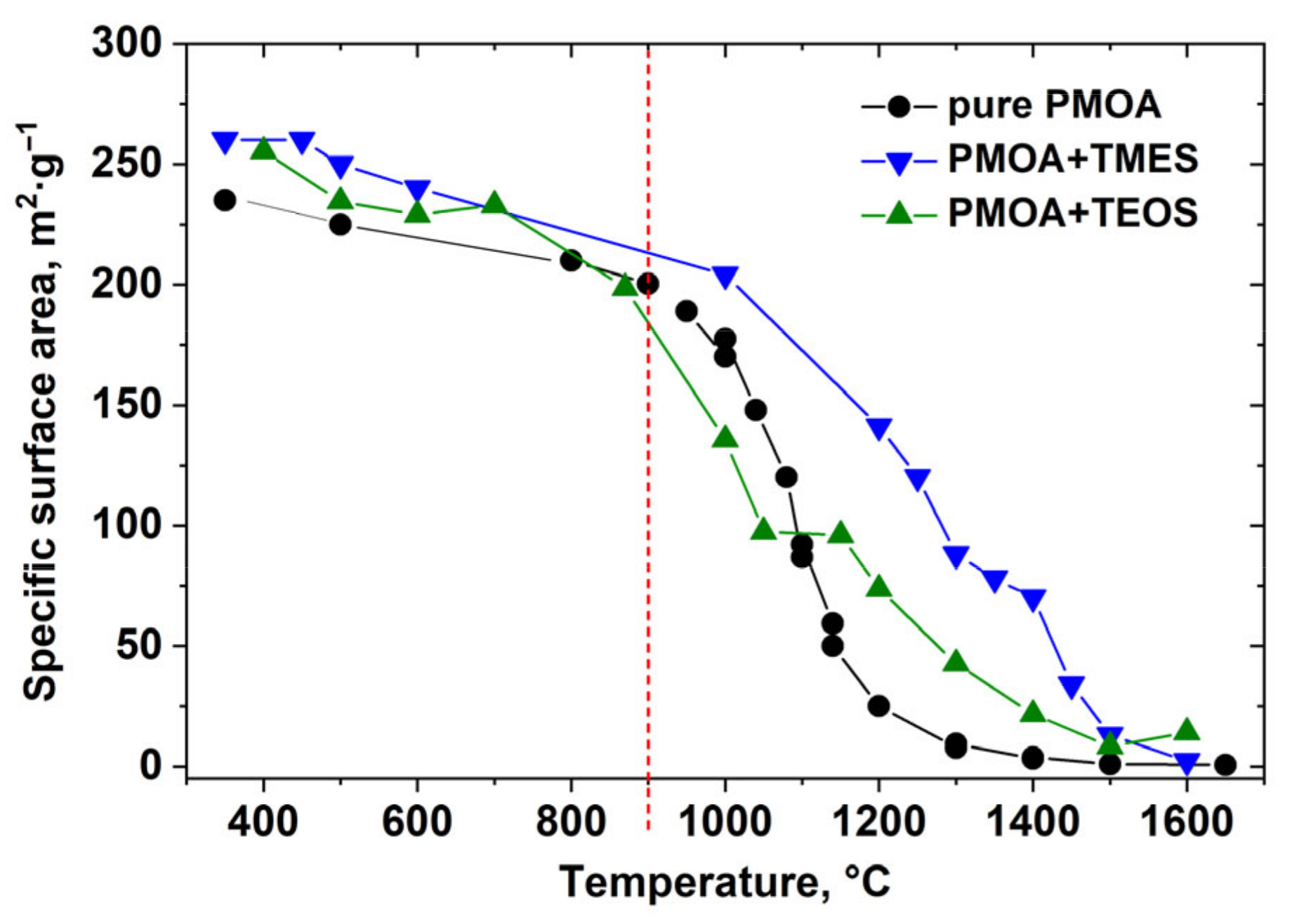
  • Up to the annealing temperature of ~900 °C, the ethoxysilane layers’ effect on specific surface area changes in PMOA+TEOS nanocomposites is noticeable; however, the mass density increase relative to pure PMOA does not exceed 20 m2/g. We attribute this modest modification to the diffusion-limited reactions at the interface between alumina and silica [21];
  • The maximum bulk mass density difference between PMOA+TEMS and pure PMOA achieved at T ~1200 °C is 120 m2/g, while it does not exceed 50 m2/g in PMOA+TEOS. This increase is due to different initial conditions in the formation of 3D nanostructures in raw PMOA, PMOA+TEMS, and PMOA+TEOS;
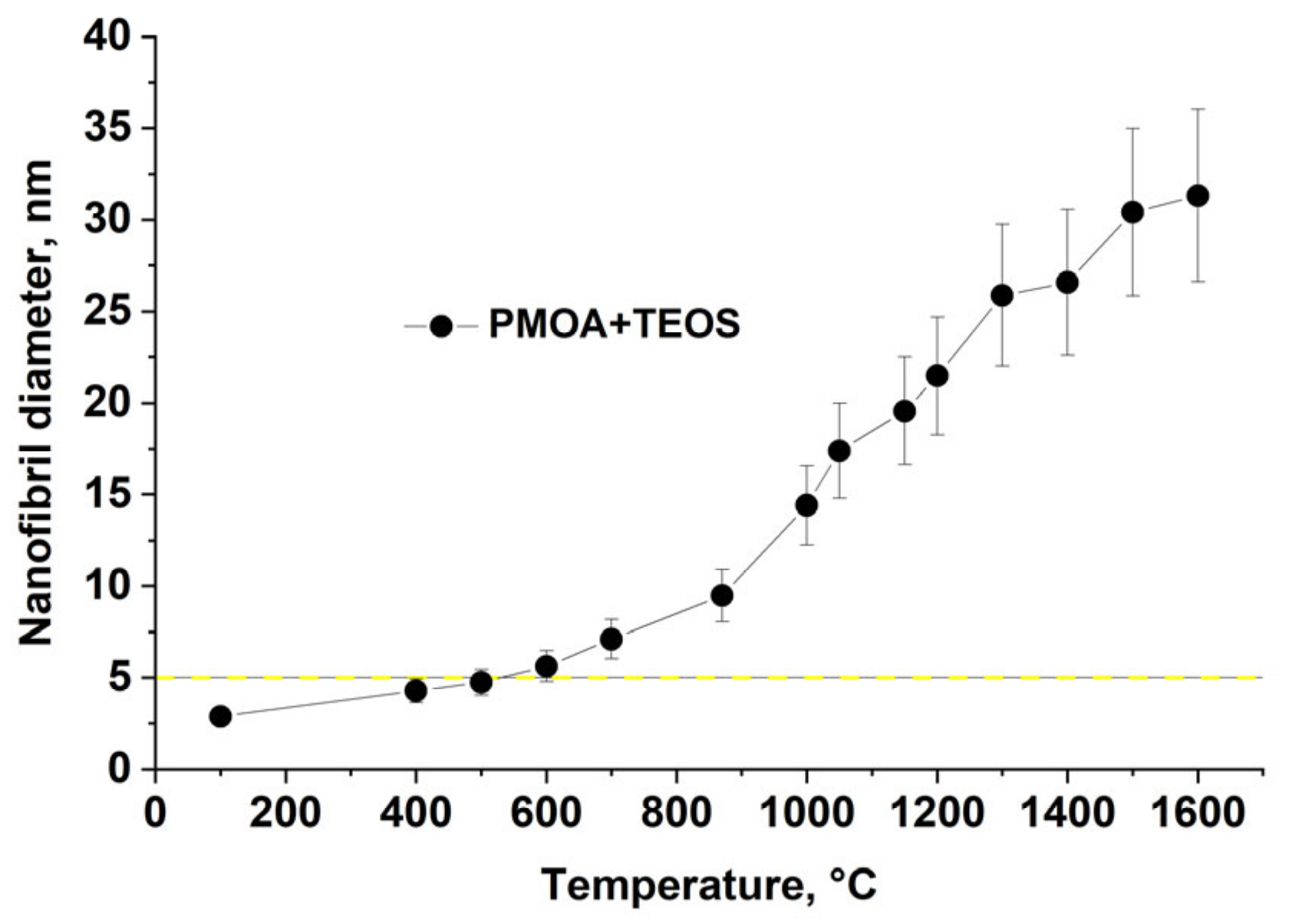
  • Annealing at temperatures above 1450 °C leads to the stabilization of the 3D structure parameters: the fibrils acquire an ellipsoidal shape with the characteristic size of ≤ 2 μ for pure PMOA [20] and up to 70 nm for PMOA+TEOS samples (Figure 5). It is important to note that the solid-phase synthesis of mullite after 4 h annealing at temperatures T ≥ 1400 °C begins at the alumina–silica interface.

3.2. Nanomullite Synthesis from Aluminosilicate Nanocomposites

The mullite precursors prepared from pre-annealed PMOA+TEOS composites have a 3D framework of interconnected nanoparticles. The mullite synthesis of a given stoichiometry requires controlling not only the chemical composition of the precursor and the molecular ratio of the Al2O3 and SiO2 components, but also their morphologies: the size of the aluminum oxide particles and the layer thickness of silica.
The most effective method of silica deposition appeared to be the exposure of PMOA saturation with vapour or liquid TEOS, which allowed us to obtain the maximum amount of silica on the PMOA surface compared to TMES and MTMS. Figure 5 shows the kinetics of SiO2 deposition on raw PMOA when saturated with TEOS vapour at room temperature. The deposition rate slowed down significantly after t ≥ 15 h and the maximum silica content Si/Al ≈ 27% mol was attained.
Figure 5. Silicon content in Al2O3-SiO2 nanocomposite depending on contact time with TEOS vapour at room temperature.
Jcs 08 00469 g005
The average diameter of the basic nanofibril of the PMOA+TEOS precursor, prepared from raw PMOA treated in TEOS vapour, is shown in Figure 6.
It has been shown [17,21] that the presence of an amorphous silica layer on an alumina surface significantly affects the morphology and structural phase transformations of PMOA nanofibrils. A comparison of the results obtained for PMOA + TEOS (Table 1) and the available literature data for PMOA + MTMS [21] (Table 2) permits us to conclude that the structural phase transformations remain the same, despite some differences in the temperatures at which phase transformations occur. By generalizing the physical model of the structural and chemical evolution of PMOA [20,21], the following main stages of mullite synthesis can be distinguished:
-
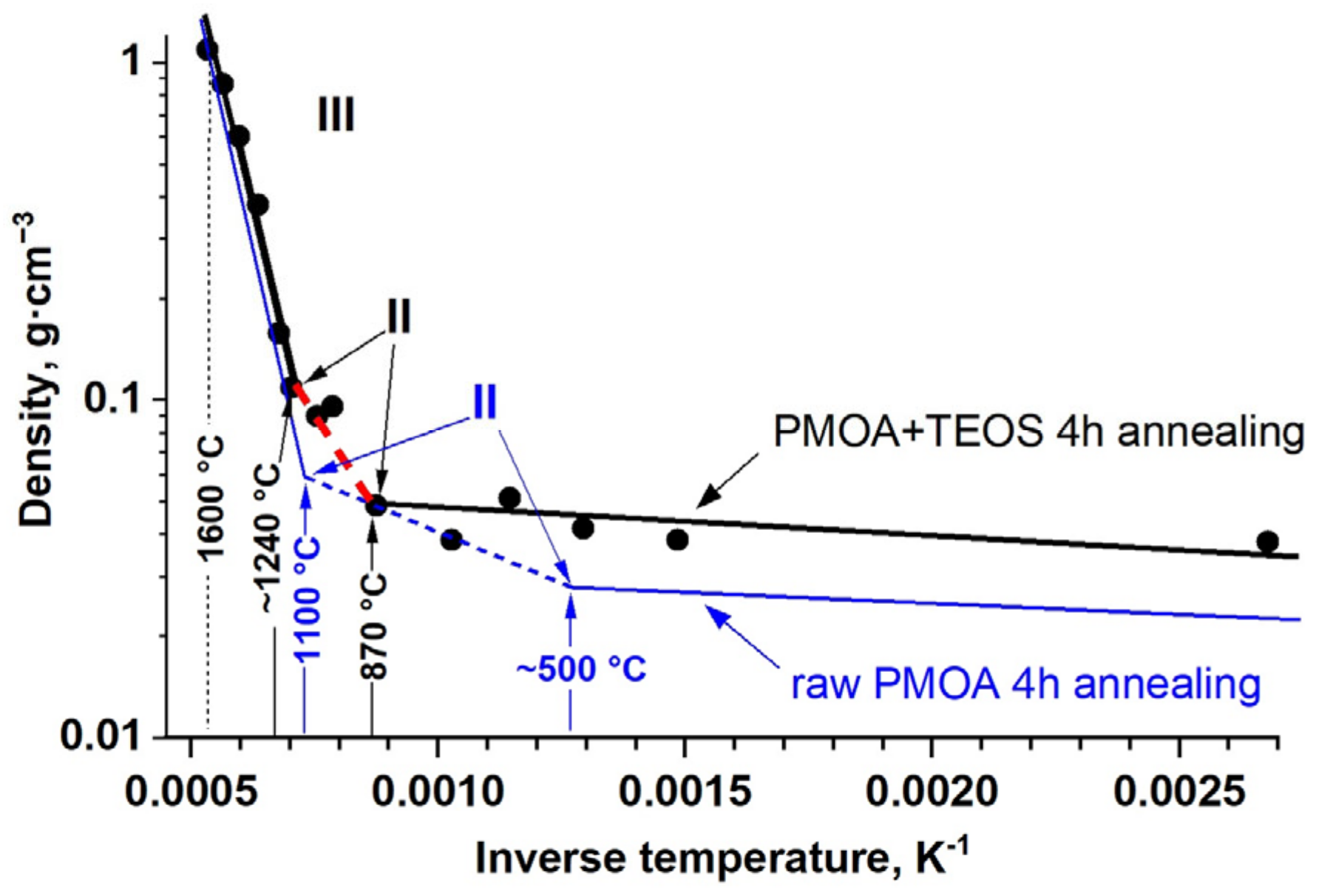
T ≤ 870 °C. Dehydration of aluminum oxyhydroxide. The presence of an amorphous SiO2 layer on the nanofibril surface limits water desorption and the formation of pre-boehmite structural elements;
-
T ≤ 1000 °C. Changes in nanofibril morphology and decreases in specific surface area due to the activation of diffusional processes inside the fibrils (Figure 3). The surface diffusion in the nanofibrils is significantly limited by the presence of an amorphous SiO2 layer. The crystallization begins, resulting in the formation of the γ-Al2O3 phase;
-
T ≤ 1300 °C. Beginning of the structural phase transformation γ-Al2O3 → θ-Al2O3;
-
T ~ 1350 °C. Beginning of the structural phase transformation θ-Al2O3 → α-Al2O3;
-
T ≥ 1400 °C. Beginning of mullite synthesis at the α-Al2O3 fibril interfaces with amorphous SiO2.
The dependence of the volume mass density of PMOA+TEOS on inverse temperature shown in Figure 4 clearly distinguishes domains with different activation energies, which can be interpreted as the sequential activation of three main mechanisms of the 3D structure evolution: dehydration, diffusion transport, and sintering (Table 1). In the low-temperature ranges I and II (T < 1100 °C), the bulk mass density of PMOA+TEOS (liquid) differs significantly from that of raw PMOA, while in the high-temperature range III (T ≥ 1200 °C), the experimental data in Figure 4 practically coincide.
The silicon content in the highest 3/2-mullite: 3Al2O3 2SiO2 is 33.3 mol%, which is larger than that after the TEOS vapour deposition, where the maximum silicon content of Si/Al ≈ 27 mol% was obtained (Figure 5). The silicon content in annealed PMOA+TEOS precursors can be increased by using additional impregnation with liquid TEOS, but the quantitative reproducibility of this process was not satisfactory. For this reason, the nanomullite synthesis was carried out with PMOA+TEOS (vapour) samples, in which the maximum deposited SiO2 amount was sufficient for the synthesis of 2/1-mullite 2Al2O3·SiO2 (Si/Al = 25 mol%) and mullites with a lower silicon content.

3.3. Nanomullite Synthesis from the Aluminosilicate Nanocomposites

The mullite structure was formed in the Al2O3-SiO2 nanocomposites after 4 h annealing at T ≥ 1400 °C [17,21] (see Table 1). The synthesis includes two stages: heating PMOA+TEOS precursors to 1000 °C with the dwell time of 4 h at this temperature, after which the temperature was raised to 1400 °C and the synthesis was continued in the pure oxide nanosystem Al2O3-SiO2 for some time. In the present experiments, the time to complete nanomullite synthesis was 18 h. It is important to note that the general initial structure of the precursor was preserved during the nanomullite synthesis: monolithic porous 3D nanomaterial.
The influence of annealing duration on the modification of the 3D structure of PMOA+TEOS precursor was studied by varying the processing time from 4 to 72 h at T = 1400 °C, as shown in Figure 7 and Figure 8. The results evidenced that mullite formation kinetics continue until a complete dissolution of the surface amorphous silica layer into alumina nanofibril. In particular, it was found that 18 h of annealing led to an increase in the volume mass density of nanomullite up to ~0.9 g/cm3 while the nanofibril diameter increased to ~ 48 nm. The annealing for 4 h at a higher temperature of 1600 °C slightly increased the bulk mass density of nanomullite up to 1.2 g/cm3, the average diameter of nanofibrils increased to 60 nm, and the porosity of 3D nanostructure smoothly decreased to 72%. The general changes in the 3D structure and morphology of PMOA+TEOS precursors during the nanomullite synthesis relative to the original structure of raw PMOA can be outlined as follows: the diameter of the basic nanofibril increases more than 10 times from ~5 nm to ~60 nm; the porosity decreases from 99% to 72%; and the bulk mass density increases more than 50 times from 0.02 to ~1 g/cm3.
Complimentarily, by broadening the XRD peaks by the Scherrer method, the average sizes of the nanomullite crystallites were confirmed: ~10 nm at T = 1000 °C, 30 nm at T = 1200 °C, and ~60 nm at T = 1600 °C. It is worth mentioning that the XRD patterns obtained during the annealing of PMOA+TEOS precursors do not differ from those previously obtained for PMOA+TMES (see Ref. [21] for a comparison).
The morphological changes in the nanomullite crystallites were studied using SEM and TEM images, and the degree of crystallinity was assessed from the HEED data, as shown in Figure 9 and Figure 10.
It was found that the crystallization of nanomullite led to changes in the shape of the elementary fibril: it took the form of a hexagonal prism with an aspect ratio (length-to-diameter) of ≤ 3, which gradually increased up to ~5 upon annealing for 48 h (Figure 10b). With further annealing, the size of the crystallites increased but their aspect ratio decreased to ~ 2.5. The completion of nanomullite synthesis was characterized by arraigning the maximum crystallite size of 60 nm and the cessation of changes, which can be observed in the TEM images in Figure 10c—annealing at T = 1400 °C for 72 h, and Figure 11—annealing at T = 1600 °C for 4 h.
The physical model, previously proposed for the quantitative description of the evolution of the 3D nanostructure of PMOA [20,27], was successfully applied to describe the synthesis of nanomullite (Table 1). A quite good agreement between the model calculations and experimental data was achieved both in the low-temperature range T < 1100 °C (stages II–III, caused by diffusion mass transfer and the onset of crystallization) and in the high-temperature range T > 1100 °C (stages IV–VII, associated with volume mass transport, crystallization, and sintering [28,29]). The physical model parameters are listed in Table 2.
Based on the obtained results, it can be assumed that the nanofibril size (initially 5–10 nm in raw PMOA) is the key parameter that defines the evolution of the 3D structure and final morphology of nanomullite. An important factor of this synthesis is the SiO2 layer on the nanofibril surface, which limits dehydration and delays the crystallization of γ-Al2O3; furthermore, it restricts surface diffusion and stabilizes material morphology. As a consequence of its extremely large specific surface area, the extended Al2O3-SiO2 interface is preserved for further reactions, including mullite formation.
Table 2. Parameters of physical model (refs. [22,23]) describing evolution of 3D nanostructures of PMOA-based materials.
Physical Processes and the Model ParametersRaw PMOAPMOA + MTMSPMOA + TEOS
Stages I–III: Dehydration, Diffusion, Crystallization. The nanofibril density is ≈ 2.25 g/cm3
The dominant process is diffusion at the surfaces and interfaces:
Pre-exponential factor D0, m2/s
Activation energy of diffusion ED, kJ/mol
6.0·10−18
28
3.5·10−17
68.5
2.33∙10−18
61
Stages IV–VIII: Crystallization, Sintering, Mullite synthesis. The nanofibril density is ≈ 3.1 g/cm3.
The dominant process is sintering:
Free volume constant (shrinkage rate) B0, s−1
Activation energy of the sintering Eb, kJ/mol
2.3·10−2
58
1.23·10−1
87.5
1.2·10−2
92.1

4. Conclusions

This work completes the cycle of studies on the understanding and control of the chemical and structural transformations in highly porous monolithic 3D nanomaterials consisting of fibrillar aluminum oxyhydroxides. The sequence of structural phase and morphological transformations in aluminosilicate nanocomposites was studied in detail in this work with the goal of nanomullite synthesis, starting from novel nanostructured precursors. As a result, the nanophase mullite was synthesized possessing a general 3D nanostructure, characteristic of the original PMOA nanomaterial. The obtained results diversify a family of monolithic 3D nanomaterials based on the original PMOA. They will be useful for the design of new functional materials with an 3D open structure for applications in catalysis, high-temperature filters, microwave antenna, environmental protection, etc.

Author Contributions

Conceptualization, A.K. (Anatole Khodan) and A.K. (Andrei Kanaev); methodology and investigation, A.K. (Anatole Khodan), T.H.N.N. and A.K. (Andrei Kanaev); software and validation, A.K. (Anatole Khodan); writing—review and editing, A.K. (Anatole Khodan), T.H.N.N. and A.K. (Andrei Kanaev). All authors have read and agreed to the published version of the manuscript.

Funding

This work was funded by the Russian Science Foundation: 22-23-01011 “New Composite Materials and Protective Coatings Based on 3D Porous Corundum Structures Filled with Tungsten or Tungsten Carbides Possessing Elevated Resistance in Gas and Plasma Flows with High Energy”.

Data Availability Statement

The data presented in this study are available on request from the corresponding author.

Acknowledgments

We thank the staff of the Center for Science Equipment of Derzhavin TSU for carrying out measurements and discussing the results.

Conflicts of Interest

The authors declare no conflicts of interest.

References

  1. Bowen, N.L.; Greig, J.W. The System: Al2O3·SiO2. J. Am. Ceram. Soc. 1924, 7, 238–254. [Google Scholar] [CrossRef]
  2. Aramaki, S.; Roy, R. Revised Phase Diagram for the System Al2O3−SiO2. J. Am. Ceram. Soc. 1962, 45, 229–242. [Google Scholar] [CrossRef]
  3. Fischer, R.X.; Schneider, H.; Schmücker, M. Crystal structure of Al-rich mullite. Am. Mineral. 1994, 79, 983–990. [Google Scholar]
  4. Lazic, B.; Krüger, H.; Kaindl, R.; Perfler, L.; Kremenovic, A.; Cvetkovic, V.; Withers, R.L. Superstructure of Mullite-type KAl9O14. Chem. Mater. 2013, 25, 496–502. [Google Scholar] [CrossRef]
  5. Schneider, H.; Fischer, R.X.; Schreuer, J. Mullite: Crystal Structure and Related Properties. J. Am. Ceram. Soc. 2015, 98, 2948–2967. [Google Scholar] [CrossRef]
  6. Zhang, X.; Zhang, T.; Yi, Z.; Yan, L.; Liu, S.; Yao, X.; Guo, A.; Liu, J.; Hou, F. Multiscale mullite fiber/whisker reinforced silica aerogel nanocomposites with enhanced compressive strength and thermal insulation performance. Ceram. Int. 2020, 46, 28561–28568. [Google Scholar] [CrossRef]
  7. Epicier, T.; O’Keefe, M.A.; Thomas, G. Atomic imaging of 3:2 mullite. Acta Cryst. 1990, A46, 948–962. [Google Scholar] [CrossRef]
  8. Aryal, S.; Rulis, P.; Ching, W.Y. Mechanical Properties and Electronic Structure of Mullite Phases Using First-Principles Modeling. J. Am. Ceram. Soc. 2012, 95, 2075–2088. [Google Scholar] [CrossRef]
  9. Aksay, I.A.; Dabbs, D.M.; Sarikaya, M. Mullite for Structural, Electronic, and Optical Applications. J. Am. Ceram. Soc. 1991, 74, 2343–2358. [Google Scholar] [CrossRef]
  10. Klug, F.J.; Prochazka, S.; Doremus, R.H. Alumina-Silica Phase Diagram in the Mullite Region. J. Am. Ceram. Soc. 1987, 70, 750–759. [Google Scholar] [CrossRef]
  11. Cui, K.; Zhang, Y.; Fu, T.; Wang, J.; Zhang, X. Toughening Mechanism of Mullite Matrix Composites: A Review. Coatings 2020, 10, 672. [Google Scholar] [CrossRef]
  12. Cameron, W.E. Mullite: A Substituted Alumina. Am. Mineral. 1977, 62, 747–755. [Google Scholar]
  13. Lenz, S.; Schneider, H.; Fischer, R.X. Mullite-type Na0.67Al6O9.33 and a discussion of iota-alumina. J. Eur. Ceram. Soc. 2020, 40, 4276–4280. [Google Scholar] [CrossRef]
  14. Saito, Y.; Takei, T.; Hayashi, S.; Yasumori, A.; Okada, K. Effects of Amorphous and Crystalline SiO2 Additives on γ-Al2O3-to-α-Al2O3 Phase Transitions. J. Am. Ceram. Soc. 1998, 81, 2197–2200. [Google Scholar] [CrossRef]
  15. Horiuchi, T.; Sugiyama, T.; Mori, T. Factors for maintenance of a high surface area of silica-coated α-alumina after heating > 1573 K. J. Mater. Chem. 1993, 3, 861–865. [Google Scholar] [CrossRef]
  16. Mizushima, Y.; Hori, M. Preparation of heat-resistant alumina aerogels. J. Mater. Res. 1993, 8, 2993–2999. [Google Scholar] [CrossRef]
  17. Mazerolles, L.; Michel, D.; di Costanzo, T.; Vignes, J.L. New Developments in Nanometric Porous Mullite, Spinel, and Aluminas. In Innovative Processing and Synthesis of Ceramics, Glasses, and Composites VI; Bansal, N.P., Singh, J.P., Eds.; Ceramic Transactions; The American Ceramic Society: Columbus, OH, USA, 2002; Volume 135, pp. 227–235. [Google Scholar]
  18. Beguin, B.; Garbowski, E.; Primet, M. Stabilization of alumina toward thermal sintering by silicon addition. J. Catal. 1991, 127, 595–604. [Google Scholar] [CrossRef]
  19. Katada, N.; Ishiguro, H.; Muto, K.; Niwa, M. A heat-resisting acid catalyst: Thermal stability and acidity of a thin silica layer on alumina calcined at 1493 K. Chem. Vap. Depos. 1995, 1, 54–60. [Google Scholar] [CrossRef]
  20. Khodan, A.; Nguyen, T.H.N.; Esaulkov, M.; Kiselev, M.R.; Amamra, M.; Vignes, J.-L.; Kanaev, A. Porous monoliths consisting of aluminum oxyhydroxide nanofibrils: 3D structure, chemical composition, and phase transformations in the temperature range 25–1700 °C. J. Nanopart. Res. 2018, 20, 194. [Google Scholar] [CrossRef]
  21. Khodan, A.; Kanaev, A.; Esaulkov, M.; Kiselev, M.; Nadtochenko, V. Effects of Surface Chemical Modification by Ethoxysilanes on the Evolution of 3D Structure and Composition of Porous Monoliths Consisting of Alumina Hydroxide Nanofibrils in the Temperature Range 25–1700 °C. Nanomaterials 2022, 12, 3591. [Google Scholar] [CrossRef]
  22. Khatim, O.; Nguyen, T.H.N.; Amamra, M.; Museur, L.; Khodan, A.; Kanaev, A. Synthesis and photoluminescence properties of nanostructured mullite/-Al2O3. Acta Mater. 2014, 71, 108–116. [Google Scholar] [CrossRef]
  23. Seong, H.K.; Kim, U.; Kim, M.H.; Choi, H.J.; Lee, Y.; Seo, W.S. Synthesis and optical properties of mullite nanowires. J. Am. Ceram. Soc. 2007, 90, 1937–1939. [Google Scholar] [CrossRef]
  24. Vignes, J.-L.; Mazerolles, L.; Michel, D. A novel method for preparing porous alumina objects. Key Eng. Mater. 1997, 132–136, 432–435. [Google Scholar] [CrossRef]
  25. Di Costanzo, T.; Fomkin, A.A.; Frappart, C.; Khodan, A.N.; Kuznetsov, D.G.; Mazerolles, L.; Michel, D.; Minaev, A.A.; Sinitsin, V.A.; Vignes, J.-L. New Method of Porous Oxide Synthesis: Alumina and Alumina Based Compounds. Mater. Sci. Forum. 2004, 453–454, 315–322. [Google Scholar] [CrossRef]
  26. Vignes, J.-L.; Frappart, C.; di Costanzo, T.; Rouchaud, J.-C.; Mazerolles, L.; Michel, D. Ultraporous monoliths of alumina prepared at room temperature by aluminium oxidation. J. Mater. Sci. 2008, 43, 1234–1240. [Google Scholar] [CrossRef]
  27. Khodan, A.N.; Bykov, A.V.; Kiselev, M.R. The Effect of Chemical Modification of the Surface by Oxysilanes on Changes in the Structural and Phase States of Highly Porous Aluminum Oxyhydroxides at Annealing up to 1200 °C. Prot. Met. Phys. Chem. Surf. 2023, 59, 145–150. [Google Scholar] [CrossRef]
  28. Geguzin, Y.E. Diffusion porosity in metals and alloys. Phys.-Uspekhi Adv. Phys. Sci. 1957, LXI, 217–247. [Google Scholar]
  29. Ivensen, V.A. Use of a mathematical model for pore volume shrinkage over a wide temperature range. Powder Metall. Met. Ceram. 1996, 34, 528–533. [Google Scholar] [CrossRef]
Figure 1. TEM images and corresponding HEED patterns: (a) PMOA treated with TEOS vapour at room temperature, and (b) after annealing at 1400 °C for 4 h.
Jcs 08 00469 g001
Figure 2. XRD patterns of PMOA+TEOS and raw PMOA after 4 h annealing at 1400 °C.
Jcs 08 00469 g002
Figure 3. Specific surface area versus annealing temperature of raw PMOA and silica-modified PMOA treated at room temperature with TEMS vapour and liquid TEOS. The onset of crystallization of amorphous pre-boehmite structures into the γ-Al2O3 phase is shown by the red dotted line.
Jcs 08 00469 g003
Figure 4. Mass density evolution after annealing of PMOA+TEOS nanocomposite (Al2O3-SiO2) precursors. Blue line shows results of raw PMOA.
Jcs 08 00469 g004
Figure 6. Average diameter of nanofibrils in PMOA+TEOS precursors after isochronous annealing.
Jcs 08 00469 g006
Figure 7. Volume mass density of PMOA+TEOS precursor during synthesis of nanomullite at 1400 °C.
Jcs 08 00469 g007
Figure 8. Average diameter of nanofibrils in PMOA+TEOS precursors during synthesis of nanomullite at 1400 °C.
Jcs 08 00469 g008
Figure 9. SEM images of a nanomullite sample synthesized from a PMOA+TMES precursor at 1400 °C for 4 h.
Jcs 08 00469 g009
Figure 10. TEM images and corresponding HEED patterns of nanomullite annealed at 1400 °C for (a) 24 h, (b) 48 h, and (c) 72 h.
Jcs 08 00469 g010
Figure 11. TEM image of PMOA+TEOS precursor annealed at 1600 °C for 4 h.
Jcs 08 00469 g011
Table 1. Temperature * of the beginnings of the structural phase transformations in the PMOA+TEOS precursors and temperature shifts in phase transitions relative to raw PMOA.
StageStructural and Phase TransformationsTransition Temperature
PMOAPMOA + TEOSShift, ΔT
I–IIPolymolecular polynuclear state → Amorphous phase≤100≤120~20
II–IIIDehydration: Amorphous phase →
Amorphous phase with the elements of pre-boehmite structures
≤460≤870~400
III–IVCrystallization: Amorphous pre-boehmite structures → γ-Al2O3≤700≥900~200
IV–VCrystallization + Sintering: γ-Al2O3 → θ-Al2O3≤1050≤1300~250
V–VIθ-Al2O3 → α-Al2O3≤1100≥1350~250
VIIMullite synthesis-≥1400-
* The temperature of isochronous annealing during 4 h.
Disclaimer/Publisher’s Note: The statements, opinions and data contained in all publications are solely those of the individual author(s) and contributor(s) and not of MDPI and/or the editor(s). MDPI and/or the editor(s) disclaim responsibility for any injury to people or property resulting from any ideas, methods, instructions or products referred to in the content.

