Article

Experimental and Numerical Study of Bearing Damage of a CF-LMPAEK Thermoplastic Composite

Applied Mechanics Laboratory, Department of Mechanical Engineering and Aeronautics, University of Patras, GR-26504 Rio-Patras, Greece
*
Author to whom correspondence should be addressed.
J. Compos. Sci. 2024, 8(1), 35; https://doi.org/10.3390/jcs8010035
Submission received: 12 December 2023 / Revised: 27 December 2023 / Accepted: 15 January 2024 / Published: 18 January 2024

Abstract

:
This study focuses on investigating the behavior of a thermoplastic matrix composite (Carbon Fiber-LMPAEK) under a bearing strength determination test. The specimens were subjected to a double-shear-bolted joint configuration tensile test, and the propagation of damage was monitored using extensometers. The research employs a technique that involves inelastic modelling and considers discrepancies in layer interfaces to better understand bearing damage propagation. In this context, cohesive modelling was utilized in all composite layers, and the Hashin damage propagation law was applied. The double-shear-bolted joint configuration chosen for the test revealed critical insights into the bearing strength determination of the Carbon Fiber-LMPAEK thermoplastic matrix composite. This comprehensive approach, combining inelastic modelling and considerations for layer interfaces, provided a nuanced understanding of the material’s response to bearing forces. The results of the study demonstrated that all specimens exhibited the desired type of bearing failure, characterized by severe delamination around the hole. Interestingly, the thermoplastic matrix composite showcased enhanced bearing properties compared to traditional thermoset materials. This observation underscores the potential advantages of thermoplastic composites in applications requiring robust bearing strength. One noteworthy aspect highlighted by the study is the inadequacy of current aerospace standards in prescribing the accumulation of bearing damage in thermoplastic composites. The research underscores the need for a more strategic modelling approach, particularly in cohesive modelling, to accurately capture the behavior of thermoplastic matrix composites under bearing forces. In summary, this investigation not only provides valuable insights into the bearing strength of Carbon Fiber-LMPAEK thermoplastic matrix composites, but also emphasizes the necessity for refining aerospace standards to address the specific characteristics and failure modes of these advanced materials.

1. Introduction

Lately, aerospace industry has shown great interest in the usage of thermoplastic matrix composites for primary and secondary applications due to their recyclability and welding capability. Spirit AeroSystems’ “ASTRA” [1], Netherlands Aerospace Centre “STUNNING” [2,3,4,5] and German Aerospace Center (DLR) “LuFoV-3 TB-Rumpf” [6] fuselage panels demonstrators have been developed with a common purpose, the integrated manufacturing of skin, stiffeners, and frames that are leading in a tremendous reduction of manufacturing time and cost via the process of consolidation.
Thermoplastics are highly desirable for advanced structural applications not only due to the ongoing efforts in reforming manufacturing processes but also because of their exceptional properties, which have been well-known for decades. Despite their advantageous properties, thermoplastics have been overshadowed by thermosets in certain sectors, primarily due to historical challenges in manufacturing that have been recently addressed with the introduction of new processing technologies, leading to cost reductions.
One significant advancement is the development and exploration of Automated Fiber Placement (AFP), a method that incorporates manufacturing parameters from additive manufacturing [7,8]. AFP has emerged as a transformative technology, replacing costly and limited autoclave-based procedures. This technological shift has contributed to the increasing prominence of thermoplastics in structural applications.
Research on bearing failure in thermoplastic composites has been a focal point, covering various aspects such as drilling procedures, fastener materials, plate materials, manufacturing processes, and the geometry of joints and holes. This body of research aims to understand and optimize the performance of thermoplastic composites under bearing forces. Specific studies have delved into the intricacies of drilling procedures [9,10,11], the influence of fastener materials [12], characteristics of plate materials [13,14], manufacturing techniques [15], and the geometric aspects of joints and holes [16].
By addressing these factors, researchers seek to enhance the overall understanding of how thermoplastic composites respond to bearing forces. This knowledge is crucial for advancing the application of thermoplastics in structural components, opening new possibilities and considerations for the design and manufacturing of high-tech structures. As these advancements continue, thermoplastics are poised to play an increasingly significant role in shaping the future of structural materials and applications.
The drilling procedure in composite materials often leads to significant damage around holes, with prevalent issues like delaminations and fiber breakage. A study by A. Dickson et al. [9] demonstrated a transformative approach using additive manufacturing for thermoplastic composites, eliminating the need for drilling. In their research, this method substantially increased bearing strength, showing improvements of up to 29% for a single lap joint and an impressive 63% for a double lap joint.
Another innovative strategy, as highlighted by Y. Chenxi et al. [12] involves the use of compatible thermoplastic CF-PEEK (Carbon Fiber-Reinforced Polyether Ether Ketone) pins against titanium. This technique aims to reduce mass and eliminate the need for sealants, crucial for preventing galvanic corrosion that could lead to catastrophic failures, especially in environments with high electric conductivity that may initiate fires. The study demonstrated that CF-PEEK pins, applied through hot-press and cooling processes, exhibit higher specific strength compared to titanium. Moreover, increasing fiber volume fraction (Vf) and decreasing cooling rates were identified as factors enhancing the strength of these joints.
The ongoing competition between thermoplastic and thermoset composites, particularly in the aerospace industry, has prompted investigations into their respective merits. In addressing this question, B. Vieille and L. Taleb [14] conducted a comparative study between thermoplastic composites, specifically those with PPS (Polyphenylene Sulfide) and PEEK matrices, and common thermosets with epoxy matrices under bearing schemes with considerations for environmental conditions. The results indicated that under room temperature and dry (RTD) conditions, thermoplastic composites exhibit higher bearing strength. However, in severe hydrothermal conditions, especially after the glass transition temperature, this advantage is diminished.
Furthermore, B. Vieille et al. [15] delved into the impact of the manufacturing procedure on bearing strength capability. Comparisons between stamping and consolidation revealed that the stamping method enhances bearing strength for a CF-PPS (Carbon Fiber-Reinforced Polyphenylene Sulfide) thermoplastic composite. Collectively, these studies contribute to an evolving understanding of how various factors, ranging from manufacturing techniques to material choices, influence the bearing performance of thermoplastic composites in aerospace applications.
Many studies suggest that crack propagation initiation and fracture toughness are not influenced by the interface angle of the plies in contact, while others believe that cross-plies lead to enhanced resistance to delamination [17]. Specifically, M.M. Shokrieh et al. [18] investigated the interface fiber angle for DCB specimens and concluded that maximum bridging stress is fiber-angle-dependent, whereas the crack tip opening displacement is independent. In fact, with a raise in interface fiber angle there is a corresponding raise in fracture toughness of the interface.
Another important fact that should be taken into consideration is the inelastic and viscoelastic behavior of thermoplastic composites. Many pillar studies have proven that thermoplastic composites exhibit non-linear stress–strain curves due to the plasticity of the matrix, especially as fiber angle increases (off-axis tension). Sun and his colleagues have done much research towards the development of a one-parameter plasticity damage model for thermoplastic composites, both experimentally and numerically [19,20,21] and with temperature considerations (viscoelastic behavior) [22].
Regarding modelling techniques for bearing strength evaluation, P. Camanho and F. Mathews [23] have created a 3D model for strength prediction of mechanically fastened joints in composite materials, taking into consideration progressive damage at elastic properties of the material and a 3D failure criterion. This can be used for all three accepted types of failure in fastened joints, bearing, tension and shear-out. Similarly, the same authors [24] have used 3D numerical models to quantify stress fields at the interface between layers together with delamination criterion. It is concluded that out of plane tightening pressure affects the joint efficiency and that clamping pressure between the washer and the laminate leads to higher strength. Moreover, P. Camanho and M. Lambert [25] have developed a numerical methodology for determining damage, final failure and failure mode of composite fastened joints, applied only for double shear and quasi-isotropic laminates.
Last but not least, another aspect of this work is the implementation of Double Cantilever Beam and End Notch Flexure test results for Cohesive Zone Modelling capabilities and delamination quantification (interlaminar damage). A few works towards fracture characterization of thermoplastic materials have been surveyed. R. Giusti and G. Lucchetta [26] have recently tested a woven thermoplastic composite under Mode I and II schemes and validated numerical models using various cohesive Zone Models, such as bilinear and trilinear traction separation laws. Similarly, P. Ghabezi and M. Farahani [27,28], have examined the effect of the usage of nano-particles on bridging laws and cohesive zone modelling with extensive reference to various parameter considerations for cohesive laws. The aim of this study is the investigation of thermoplastic matrix composites used in mechanically fastened joints for aerospace applications. Numerical modelling is found to be inadequate due to contact issues, instability factors and cohesion definition. Simple techniques are suggested to tackle these difficulties. Moreover, the results of this survey are supporting the design of thermoplastic composite multi-stiffened panels via the Experimental Building Block approach [29].
In this study, double-shear-bolted joint configuration tensile tests of a CF-LMPAEK are taking place to exploit the enhanced bearing strength capabilities of thermoplastic composite materials, together with the survey of validity of the present standards for aerospace applications. In addition, a fast and efficient numerical methodology is strategically selected using cohesive zone modelling, inelastic considerations, and interface type discrepancies. Modelling is assisted by DCB and ENF tests outcomes conducted previously by the authors [29]. CF-LMPAEK, which is used in several applications by aerospace industries [30,31], presents consistent types of failure (local damages, total fracture via bearing profile) which can be perfectly predicted by the simplified approach presented here. Bolted joint configuration tests are part of an extensive experimental campaign, aiming to fully characterize the capabilities of thermoplastic composites in aerospace industries.

2. Materials and Methods

The material used for this study is the Carbon Fiber- PolyArylEtherKetone (CF-LMPAEK) by TORAY with material code Cetex® TC1225 [32]. This material is also used by AIRBUS for A350 XWB fuselage clips [31] and for A400M ice protection plates [30]. It is certified by both AIRBUS and BOEING with rapid production processing (<3 min). It has Standard Modulus Carbon Fibers with 145 gsm density, and it is delivered in the form of Unidirectional (UD) tapes. The laminate is manufactured by TORAY through consolidation, and C-SCAN evaluation took place to detect possible flaws.

2.1. Material Properties

The material properties are obtained from TORAY’s product datasheet [32] together with the assumption of transversely isotropic behavior ( E 2 = E 3 ,   v 12 = v 13 ,   G 12 = G 13 ,   v 23 = 1.34 × v 12 ,   G 23 = 0.4 × G 12 ) which is very common in the literature [33]. The properties are obtained from testing in room temperature dry conditions (RTD). Mechanical properties of the CETEX TC1225 material are presented in Table 1. Tension and compression tests at longitudinal and transverse fiber directions of Unidirectional Specimens provide the first 6 important values for strength and elastic modulus. The shear properties are extracted from the tension of a ±45° laminate. Moreover, the Compression after Impact Test supports the design in aspects of residual strength of the material after impact in a drop tower test machine. The material is subjected to a free fall of a mass impactor at a specific height so as to achieve 30.5 Joules of energy ( E = m g h ). The material is then tested under compression with an antibuckling device to derive the residual strength. Lastly, Mode I and Mode II tests provide the necessary information for fracture characterization since the crack propagation is investigated under out-of-plane and in-plane forces, correspondingly. The fracture toughness of composite interfaces is defined by these tests, and it can be used for delamination quantification under random loading schemes. More details for the material characterization can be found on the test standards by ASTM.

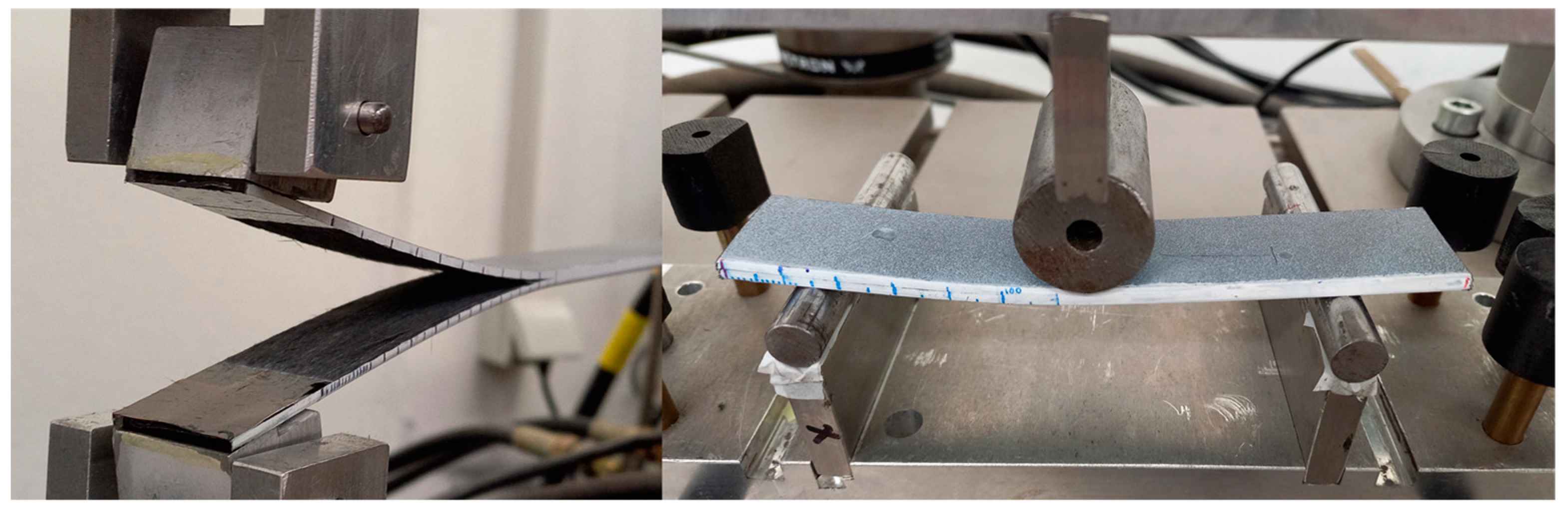
2.2. Test Selection and Definition

The European standard EN 6037:2015 [40] is selected for double-shear-joint configuration testing with the aim of testing the bearing strength determination of multidirectional laminates. The specimens must have a sufficient width for bearing failure and a 6.35 mm hole is drilled for DIN912 bolt usage, Figure 1. Moreover, the standard suggests the usage of a metallic jig that is shown in Figure 2. The procedure also demands an off-loading and reloading loop after 2% hole deformation.
The bearing test is a tensile test of a composite specimen with Filled Hole (FHT). The metallic jig of Figure 2 is used for symmetrically loading the DIN 912 bolt. Since the metal bolt has significantly higher strength than the composite, the expected type of failure is composite bearing (hole elongation) or crack propagations that lead to structural failure (net tension, shear out, cleavage and tear out). Many details about other bearing test methods can also be found by ASTM D5961 [41]. Specimens have a length of 130 mm and a width of 35 mm. The selected lamina used for the experimental building block approach of the CETEX TC12225 is [±45/90/0/90/0/90/∓45]S with a corresponding thickness of 3.6 mm. After the cut of the specimens, a 6.35 ± 0.3 mm hole is drilled for the joint configuration. Then the metallic jig is fastened, and the specimen is placed in the INSTRON 8802 test machine. Strains are monitored through an extensometer. The specimens are loaded until 2% deformation of the hole and then the off-load and reload takes place. The test takes place until the total collapse of the specimens under the desired bearing failure.
Part of the experimental campaign is the quantification of the material’s interface properties through Mode I and Mode II tests. Specifically, UD specimens undergo DCB and ENF testing via Airbus AITM standards [42,43]. Then 2D and 3D numerical models were created for the definition of the cohesive zone parameters. Screenshots from the experiment are presented in Figure 3. It should be noticed here that the Mode II properties are dominating the bearing test response, in case of mixed-mode cohesive law avoidance.

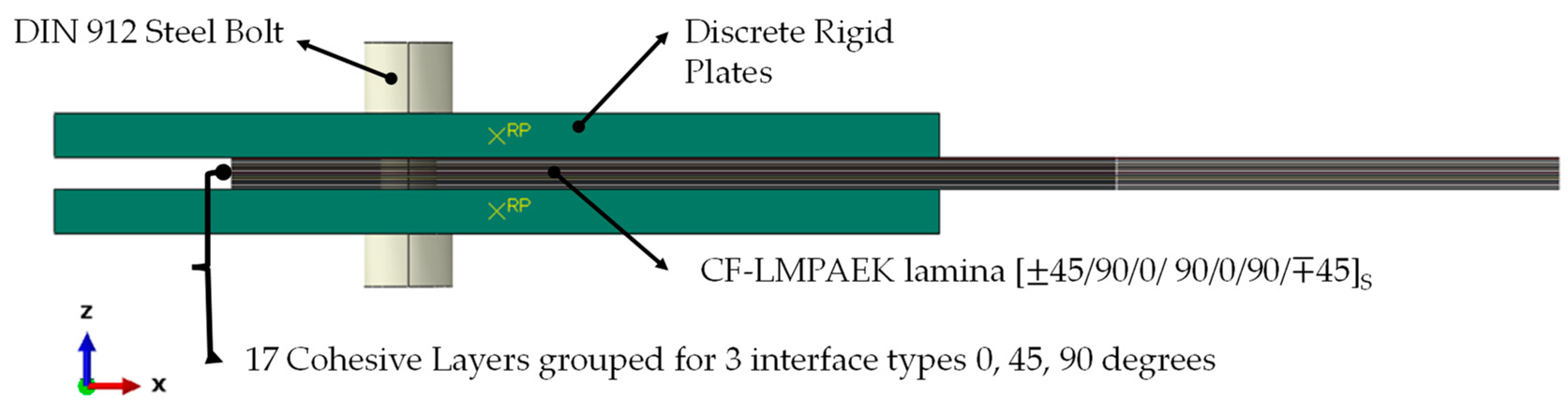
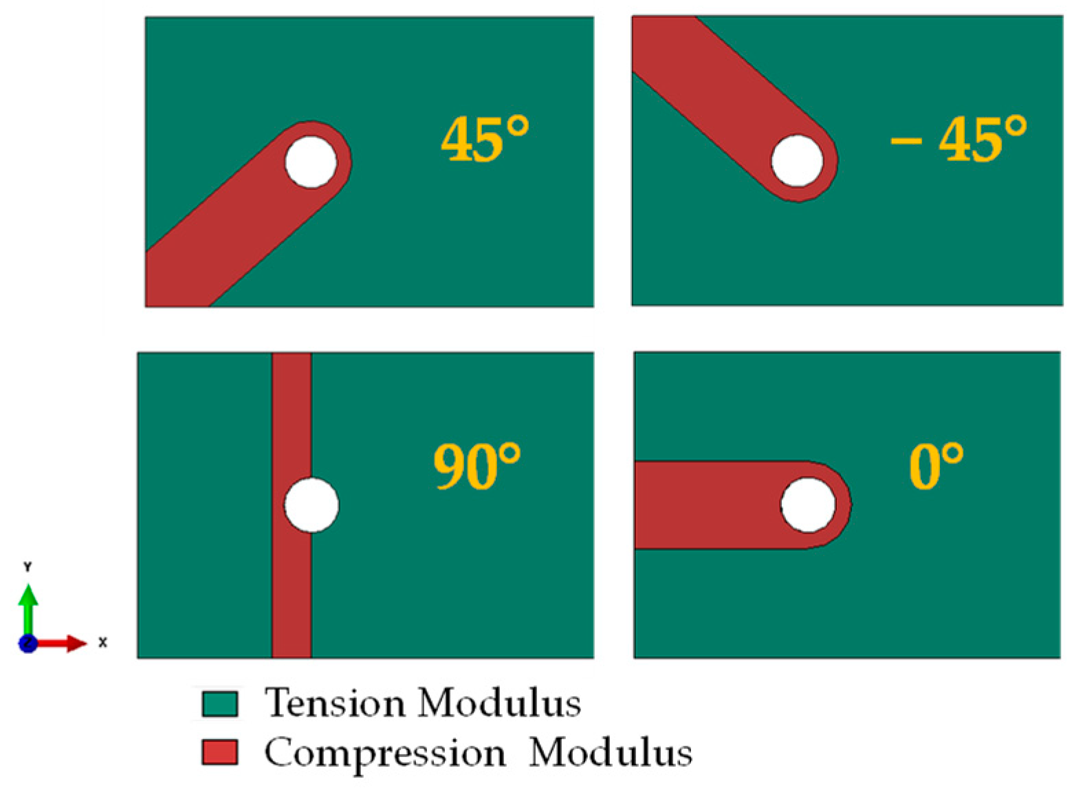
2.3. Numerical Methodology

Numerical models were created using inputs from the test/modelling campaign that aims to decode the thermoplastic behavior under the NEMO project [29]. Specifically, material characterization, fracture (see Section 2.2) and impact tests have taken place and the corresponding FE models have been adapted with the assistance of the material card properties. Calibrated FE models lead the way towards efficient comparison and forecasting, including damage initiation and propagation capabilities (intralaminar and interlaminar failure).
Fracture behavior has been simulated both with 2D plain strain and 3D solid elements, whereas characterization tests with 3D continuum shell elements and Hashin damage indices. Failure mapping has been compared to corresponding tests and has been characterized as highly sufficient. In the case of the off-axis tension test, Hashin damage criterion cannot capture the inelasticity of LMPAEK matrix. Upper-level components have also been settled with interlaminar failure via cohesive modelling which is practicable by virtue of fracture tests and modelling (see also Table 2).
Similarly, the appropriate strategy for bearing response was decided as follows:
  • 18 layers × 3D shell elements modelled separately for delamination exploitation;
  • 2 × 3D discrete rigid elements for metallic sub-plates (no point of interest);
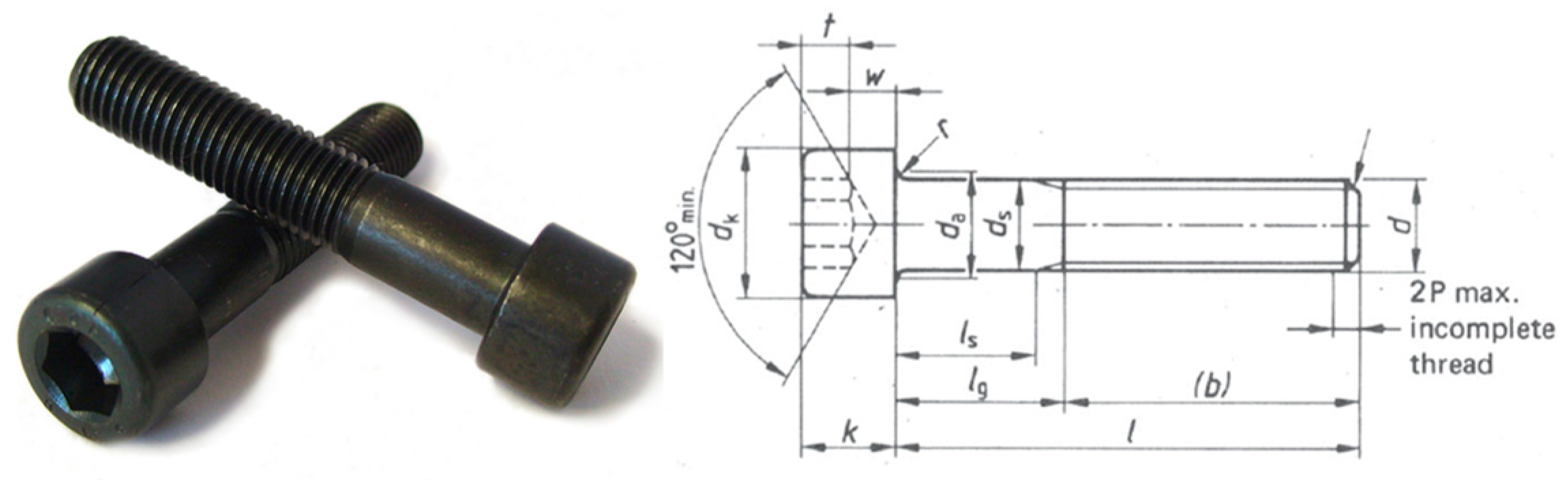
  • 1 × 3D solid elements for DIN 912 steel bolt;
  • Hashin damage propagation;
  • Explicit scheme for contact implementation and an energy check for quasi-static solution.
Furthermore, two numerical techniques have been investigated with the purpose of better capturing the damage initiation and accumulation.
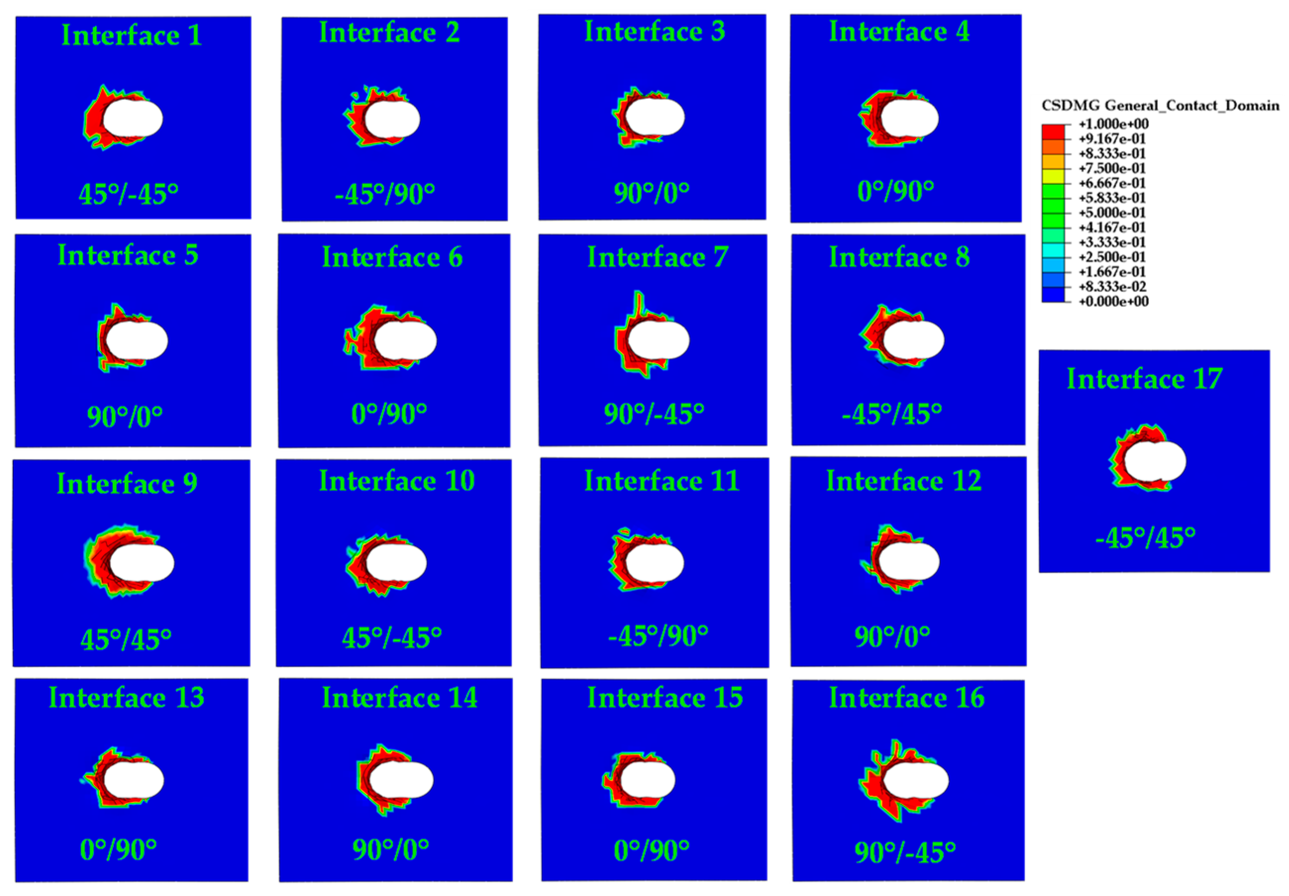
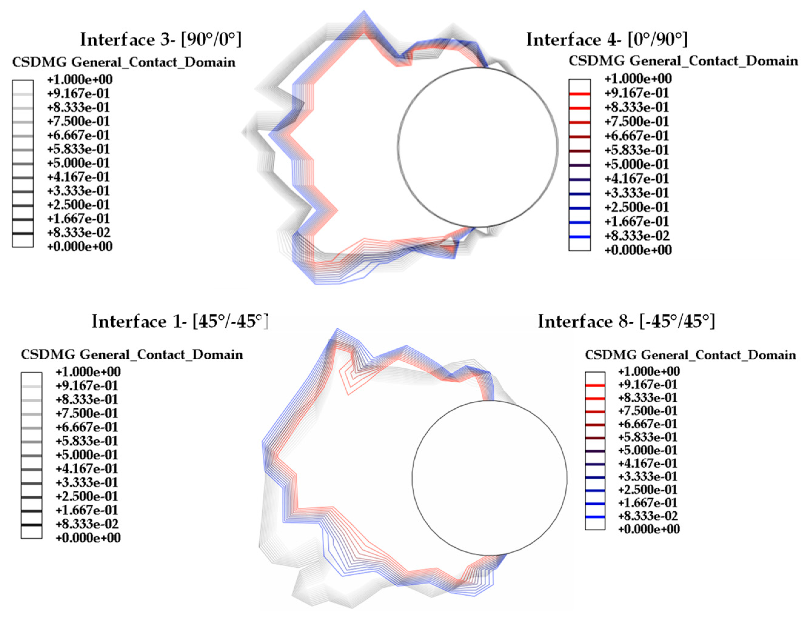
  • 17 cohesive layers grouped per interface type [0, 45, 90 degrees];
  • Inelastic behavior through 2-Step analysis for compression zone modelling.
The necessary information about cohesive modelling, which origins from calibration, is presented in Table 2, while the numerical model is presented in Figure 4. Material calibration of DCB and ENF tests have been investigated by the authors previously [29] using both 2D planar and 3D solid elements. Since the bearing test is modelled with 3D elements, it is wise to support the design with the corresponding 3D model cohesive properties. Moreover, due to the avoidance of mixed mode behavior to simulate the cohesive surfaces technique, Mode II parameters were selected since they dominate the bearing scheme. In a future study, mixed mode cohesive law could be investigated.
Due to the plastic nature of the thermoplastic matrix, severe inelastic behavior is often observed during the experimental campaign of the CETEX TC1225, especially in off axis tension where the plastic matrix plays a significant role. Furthermore, isotropic and transversely isotropic materials are considered to be linearly elastic with the same Young’s modulus in tension and compression schemes. This reflects the equality of the diagonal stiffness matrix terms ( C 11 = C 22 ). After the completion of material characterization tests, two different Young modulus values for tension and compression emerged with a discrepancy ratio of 17.4%. This finding should result in the confutation of the transversely isotropic assumption for the CETEX material and the need for further characterization with testing in out-of-plane directions (Tension at Z direction, Shear at XZ and YZ planes etc.). This would lead to high manufacturing and testing costs and is bypassed through a simplified approach for modulus discrepancies.
A 2-step model is taking place to map the differences in tension and compression areas of the layers, as seen in Figure 5 and Figure 6, for the specific type of lamina and configuration. It is common sense that the area in front of the hole is undergoing compression, following the fiber direction, whereas the rest of the structure is under tension. In the second iteration, the zones were modelled with the corresponding modulus to mitigate the non-fulfillment requirement of equal tension and compression modulus for transversely isotropic materials.
Moreover, it is common that interface properties between indifferent plies are considered the same as those coming from UD experiments. In the literature it is proven that cross-ply laminates exceed higher intralaminar fracture toughness [18] and so it is wise to model these discrepancies via empirical estimations. Although DCB and ENF tests took place to survey the UD laminas interfaces, the different angle interfaces should be considered. Ideally, additionally DCB and ENF tests should have taken place to quantify all delaminations according to each interface.
For simplicity, the difference between interface types is defined empirically, and the augmentative ratio has been extracted empirically from the work of Shokrieh et al. [18] and presented below at Table 3.
Regarding cohesive modelling, the cohesive surface technique through interaction section is selected for simplicity. Cohesive elements are avoided for extensive numerical convergence investigation matters since the length of the elements should be carefully considered. Moreover, the maximum nominal stress criterion (bilinear cohesive law) is selected together with energy evolution for the fracture toughness definition. Although mixed-mode behavior is possible to model, it is avoided since the Mode II response is dominant. In this way extensive computational costs are avoided. The stiffness coefficient of traction–separation law is a parameter under investigation and calibration. Much insightful information about traction separation law implementation was obtained by C. Shet and N. Chandra [44] and P. Ghabezi and M. Farahani [27,28].
Cohesive modelling is implemented for delamination investigations (interlaminar), which is possible due to DCB and ENF tests results. Avoidance in delamination investigation, especially around holes, would result in poor results. Together with intralaminar damage through Hashin damage propagation law, a detailed overview of the bearing response is achieved.

3. Results

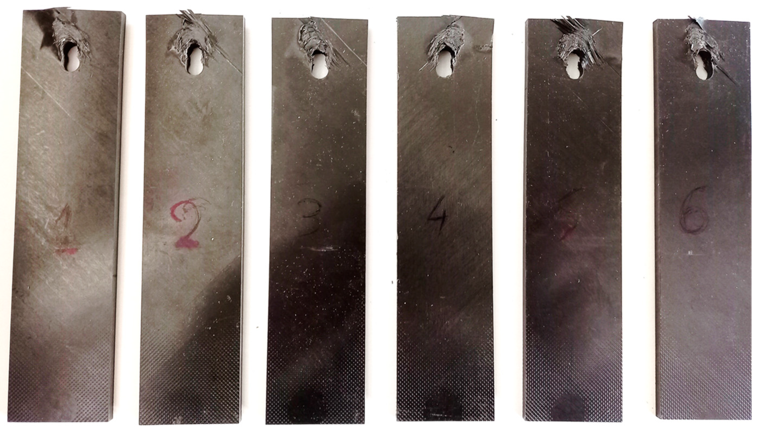
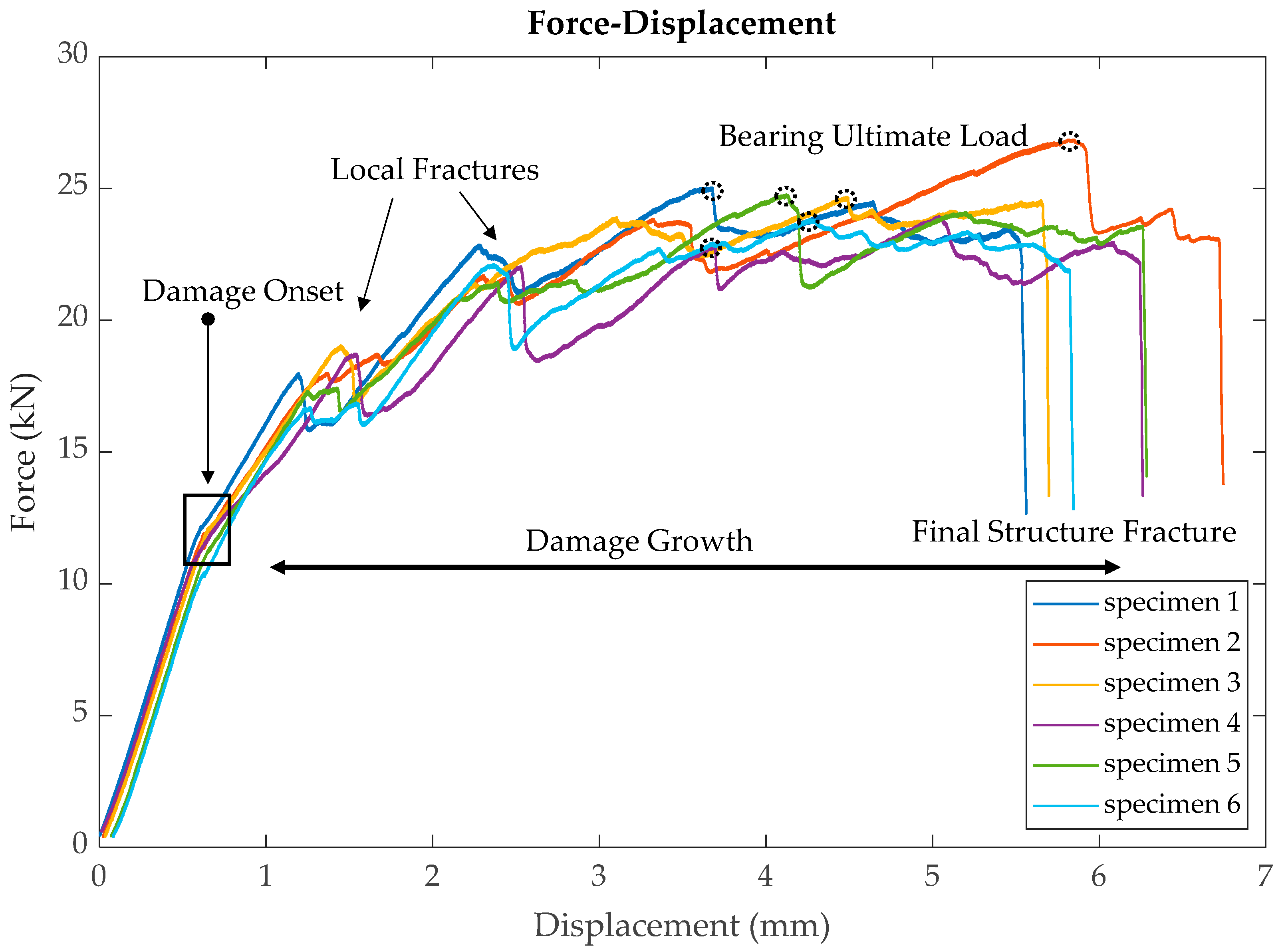
3.1. Experimental Results

The specimens were cut and placed between the metallic jig proposed by the standard for type A testing. The bolt has a pretension of 100 N / m m 2 . An extensometer with 50 mm length is placed for strain measurements. A screenshot of the experimental setup is given in Figure 7, with the corresponding setup proposed by the standard.
Specimens after testing with the bearing failure mode can be seen in Figure 8. These failure modes will be compared to the numerical results in the next Section 3.2.
The force–displacement curve was derived from the INSTRON 8802 machine due to excessive deformation of the specimens, leading to extensometer mandatory removal after 5 mm displacement. The damage onset and propagation are clearly observed, with the first noticeable drop occurring around 11.5 kN. The yield load, as considered for the off-load and reload standard, is also depicted in Figure 9 for specimens no1 and no2.
In each iteration, various yield values were explored to fulfill the requirement of 2% hole deformation. The analysis concluded that the CF-LMPAEK thermoplastic composite material falls short of meeting the 2% deformation requirement outlined in the EN6037:2015 standard. This is attributed to its high stiffness and the accumulation of damage, particularly local fractures. Specifically, the displacement at which the first failure occurs is slightly below the required 0.7 mm. This discrepancy is illustrated schematically in Figure 9. It is wise to mention here that the off-load and reload loop is part of the experimental procedure, as to enhance the specimen straightening, tightening and machine calibration. No fatigue cycles are considered, and the off-load–reload loop is successful only when damage initiation is not yet achieved.
Ultimate bearing strength was calculated through failure load divided by the hole void area D × t , where D is the bolt diameter and t is the laminate thickness. The specimens were consistent at damage growth since local fractures were initiated at the same displacements. On the contrary, failure displacements and maximum loads varied with a standard deviation of 0.44 and 1.09, correspondingly. This scattering exists due to the geometric characteristic discrepancies, as can be seen in Table 4 and the premature failure, before the 2% hole deformation that affected the damage propagation and final structure failure (Figure 9). Experiment findings are presented in Table 5.
As evident from the force–displacement (P-d) curve in Figure 10, bearing failure manifests through a combination of four distinct phases: damage onset, damage growth, local fracture, and final structural fracture. This intricate process has been extensively examined and documented by Y. Xiao and T. Ishikawa [45,46].

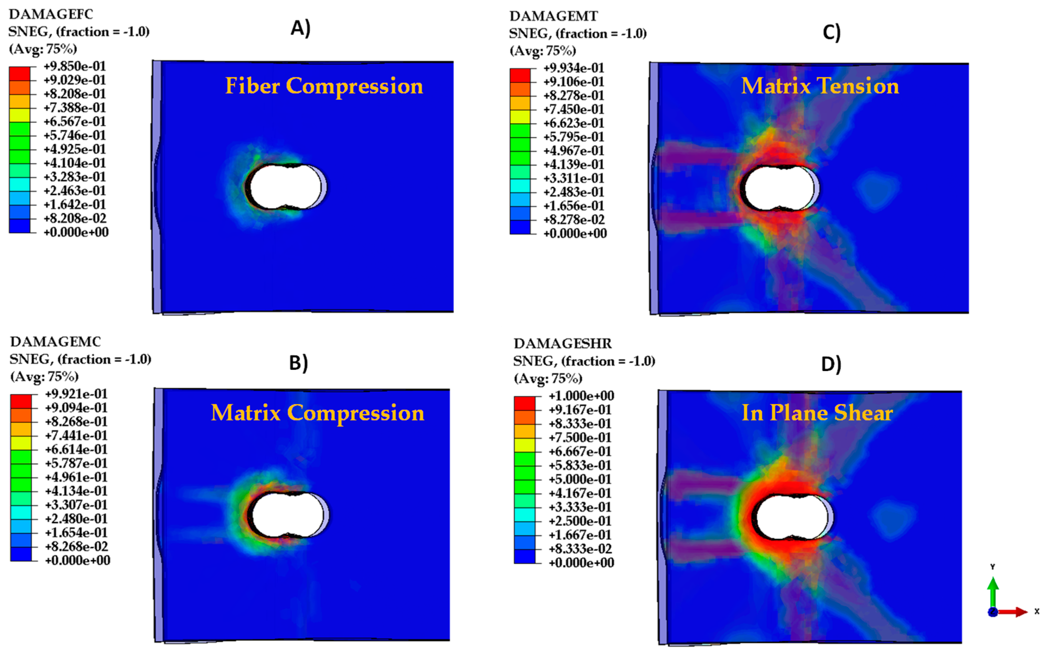
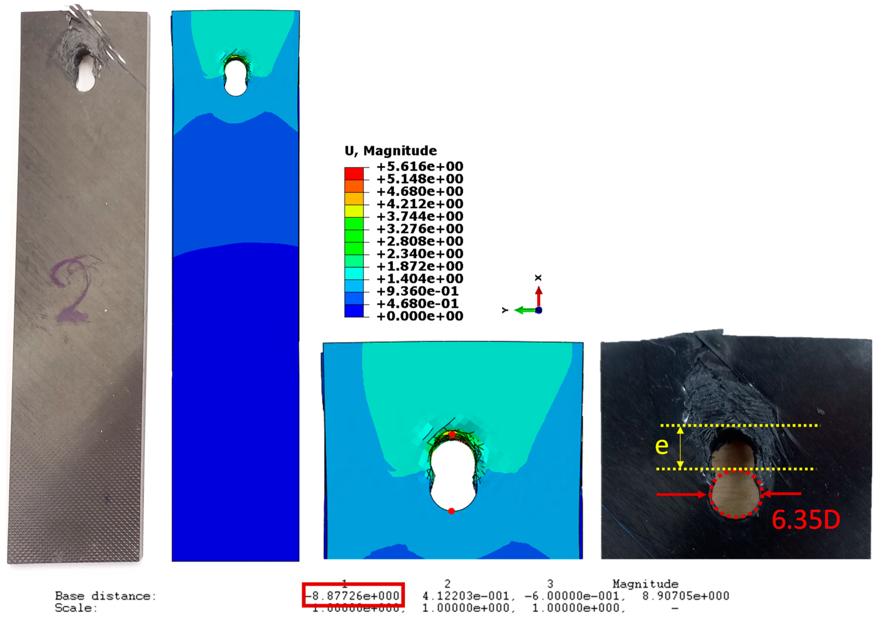
3.2. Numerical Results

In this section, the numerical results are outlined. The simplified modelling approach is notable for its speed and ability to predict the initial behavior of the bearing experiment, including factors like initial stiffness and local failures. However, it is important to note that this approach has limitations; for instance, it tends to overpredict yield failure, suggesting that the Hashin Damage propagation model alone may not be sufficient to fully describe the behavior of CF-LMPAEK.
Figure 11 provides a depiction of delamination mapping around the hole at 5 mm displacement (close to final failure) for all types of interfaces. Additionally, Figure 12 presents the damage indices for Hashin failure. The model successfully captures the type of damage characterized by delamination around the hole and local fractures. It is evident that the bearing specimens exhibit high deformation, attributed to the plasticity of the LMPAEK thermoplastic matrix. The incorporation of plasticity modelling becomes crucial for accurately simulating these displacements. Interfaces with a higher angle of fiber orientation in the sub-layers appear to have lower delamination rates.
Comparison between the delamination of layers with the same interface angle is taking place to justify the difference that comes up from different lay-up orders, for example the difference of 0°/90° and 90°/0° interface delamination (Figure 13). This is achieved only because the numerical model can verify the experimental results. Delamination analysis and investigation of the real specimens in each one of the 17 layers would be quite extensive and difficult. Moreover, cohesive zone modelling is verified through the experimental building block approach and the ENF and DCB calibrations presented on Section 2.3. So, the existence of calibrated and verified models gives the opportunity for this numerical survey.
The FE model, as can be seen in the P-d diagram in Figure 14A, is able to describe the material’s stiffness but presents an overshoot when it comes to the first failure or change of stiffness. The damage profile, propagation and force drops due to local failures can also be simulated in a good manner. In Figure 14B, a comparison between the damage profile of the experimental and numerical case is presented. Lastly, another comparison is being surveyed: the hole elongation. Real specimens are measured straight using a caliper (6.35 mm + elongation), and the numerical model elongation is measured as presented below in Figure 15. The results of the differences between the real and the numerical measurements are presented in Table 6. The comparison is quite sufficient with differences lower than 4.4%.
So, the numerical model is efficient enough to capture many characteristics of the real test and can be used for these specific reasons: fast analysis, small input from DCB and ENF tests, stiffness acquisition, damage propagation and damage profile and delamination quantification. In future work, damage initiation considerations will be better understood. Lastly, the low computational cost of the simulation is a significant plus for the establishment of the methodology for additional simulations that include fastened joints of CETEX TC1225. More specifically, a stiffened panel with fastened joints (skin to frame) is designed for multiaxial testing and bearing methodologies will support numerical modelling for forecasting reasons.

4. Conclusions

In this study, CF-LMPAEK specimens underwent a bearing test as part of a broader building block approach. The primary objective is the development of fast and efficient numerical tools for prediction and verification. However, numerical modelling of the bearing experiment poses challenges related to computational cost, instabilities, and contact issues. The presented model can predict damage indices, stiffness, delamination profiles, and local fractures. While it provides insights into damage initiation and structure collapse, these aspects cannot be entirely foreseen, requiring further research. In summary:
  • Damage onset occurs before achieving 2% hole deformation, challenging the selection of displacement and force for the off-loading and reloading loop. The high stiffness of CF-LMPAEK thermoplastic composite exceeds the criteria outlined in the EN6037: 2015 standard (Yield load displacement < 0.02xD).
  • The specimens exhibit consistent damage growth, with local fractures initiating at the same displacement. However, failure displacements and maximum loads display considerable standard deviations.
  • The chosen numerical modelling strategy for the double-shear joint is fast and simple, suitable for acquiring damage profiles and stiffness information. Hole elongation comparison led to differences lower than 4.4%.
  • The FE model struggles to predict damage initiation and final failure. It can only forecast initial stiffness, local failures, and damage profiles. A more detailed approach will be implemented in future studies to address these limitations.
  • The inelastic behavior of the thermoplastic composite should be considered for a better understanding of the damage mechanisms, especially the damage onset mechanism.
  • Thermoplastic matrix composites demonstrate enhanced bearing properties and stiffness compared to thermosets.

Author Contributions

Conceptualization, S.P. and V.K.; methodology, T.Z. and S.P.; software, T.Z.; validation, T.Z. and S.P.; formal analysis, T.Z.; investigation, T.Z., S.P. and G.S.; resources, S.P., G.S. and V.K.; data curation, S.P.; writing—original draft preparation, T.Z.; writing—review and editing, S.P. and V.K.; visualization, T.Z. and S.P.; supervision, S.P. and V.K.; project administration, V.K.; funding acquisition, V.K. All authors have read and agreed to the published version of the manuscript.

Funding

This research was funded by the European Union and Greek national funds through the Operational Program Competitiveness, Entrepreneurship, and Innovation (project code: ΓΓ2CS-0128605).

Data Availability Statement

The data presented in this study are available on request from the corresponding author. The data are not publicly available due to ongoing research findings.

Conflicts of Interest

The authors declare no conflicts of interest.

References

  1. Sloan, J. Spirit AeroSystems Debuts Next-Generation Composite Fuselage Panel; Composite World: Cincinnati, OH, USA, 2019. [Google Scholar]
  2. NLR’s STUNNING Project Departs for Next Generation Composite Plane. 2019. Available online: https://www.nlr.org/news/nlrs-stunning-project-departs-for-next-generation-composite-planes/ (accessed on 15 June 2021).
  3. van Dooren, K.; Bisagni, C. Design, analysis and testing of thermoplastic welded stiffened panels to investigate skin-stringer separation in post-buckling. Compos. Part B Eng. 2023, 267, 111033. [Google Scholar] [CrossRef]
  4. Van Dooren, K.S.; Bisagni, C. Design and analysis of thermoplastic welded stiffened panels in post-buckling. In Proceedings of the ASC 36TH Annual Technical VIRTUAL Conference: Composites Ingenuity Taking on Challenges in Environment-Energy-Economy, Online, 19–22 September 2021. [Google Scholar]
  5. van Dooren, K.S.; Labans, E.; Tijs, B.H.A.H.; Bisagni, C.; Waleson, J. Analysis and testing of a thermoplastic composite stiffened panel under compression. In Proceedings of the ICCM22—22nd International Conference on Composite Materials, Melbourne, Australia, 11–16 August 2019. [Google Scholar]
  6. Gardiner, G. DLR Institute of Structures and Design Increases Maturity of Thermoplastic Composite Fuselage Structures; Composites World: Cincinnati, OH, USA, 2021. [Google Scholar]
  7. Heathman, N.; Koirala, P.; Yap, T.; Emami, A.; Tehrani, M. In situ consolidation of carbon fiber PAEK via laser-assisted automated fiber placement. Compos. Part B Eng. 2023, 249, 110405. [Google Scholar] [CrossRef]
  8. Raps, L.; Chadwick, A.R.; Schiel, I.; Schmidt, I. CF/LM-PAEK: Characterisation and sensitivity to critical process parameters for automated fibre placement. Compos. Struct. 2022, 284, 115087. [Google Scholar] [CrossRef]
  9. Dickson, A.N.; Dowling, D.P. Enhancing the bearing strength of woven carbon fibre thermoplastic composites through additive manufacturing. Compos. Struct. 2019, 212, 381–388. [Google Scholar] [CrossRef]
  10. Borba, N.Z.; Blaga, L.; Dos Santos, J.F.; Amancio-Filho, S.T. Amancio-Filho, Direct-Friction Riveting of polymer composite laminates for aircraft applications. Mater. Lett. 2018, 215, 31–34. [Google Scholar] [CrossRef]
  11. Hufenbach, W.; Gottwald, R.; Kupfer, R. Bolted Joints with Moulded Holes for Textile Thermoplastic Composites. In Proceedings of the 18th International Conference on Composite Materials, Jeju Island, Republic of Korea, 21–26 August 2011. [Google Scholar]
  12. Yao, C.; Qi, Z.; Chen, W.; Zhang, C. Experimental study on CF/PEEK thermoplastic fastener: Effects of fastener matrix crystallinity and fibre content on the strength of single-lap joint. Compos. Part B Eng. 2021, 213, 108737. [Google Scholar]
  13. Meng, L.; Wan, Y.; Ohsawa, I.; Takahashi, J. Effects of geometric parameters on the failure behavior of mechanically fastened chopped carbon fiber tape reinforced thermoplastics. Compos. Struct. 2019, 229, 111475. [Google Scholar] [CrossRef]
  14. Vieille, B.; Aucher, J.; Taleb, L. Comparative study on the behavior of woven-ply reinforced thermoplastic or thermosetting laminates under severe environmental conditions. Mater. Des. 2012, 35, 707–719. [Google Scholar]
  15. Vieille, B.; Albouy, W.; Chevalier, L.; Taleb, L. About the influence of stamping on thermoplastic-based composites for aeronautical applications. Compos. Part B Eng. 2013, 45, 13. [Google Scholar] [CrossRef]
  16. Kelly, G.; Hallström, S. Strength and failure mechanisms of composite laminates subject to localised transverse loading. Compos. Struct. 2005, 69, 301–314. [Google Scholar]
  17. Herráez, M.; Pichler, N.; Pappas, G.A.; Blondeau, C.; Botsis, J. Experiments and numerical modelling on angle-ply laminates under remote mode II loading. Compos. Part A Appl. Sci. Manuf. 2020, 134, 105886. [Google Scholar] [CrossRef]
  18. Shokrieh, M.M.; Salamat-Talab, M.; Heidari-Rarani, M. Dependency of bridging traction of DCB composite specimen on interface fiber angle. Theor. Appl. Fract. Mech. 2017, 90, 22–32. [Google Scholar] [CrossRef]
  19. Chen, W.-H.; Lee, S.-S. Numerical and Experimental Failure Analysis of Composite Laminates with Bolted Joints under Bending Loads. J. Compos. Mater. 1995, 29, 15–36. [Google Scholar] [CrossRef]
  20. Sun, C.T.; Chen, J.L. A micromechanical model for plastic behavior of fibrous composites. Compos. Sci. Technol. 1991, 40, 115–129. [Google Scholar] [CrossRef]
  21. Sun, C.T.; Yoon, K.J. Elastic-Plastic Analysis of AS4/PEEK Composite Laminate Using a One-Parameter Plasticity Model. J. Compos. Mater. 1992, 26, 293–308. [Google Scholar] [CrossRef]
  22. Yoon, K.J.; Sun, C.T. Characterization of Elastic-Viscoplastic Properties of an AS4/PEEK Thermoplastic Composite. J. Compos. Mater. 1991, 25, 1277–1296. [Google Scholar]
  23. Camanho, P.P.; Matthews, F.L. A Progressive Damage Model for Mechanically Fastened Joints in Composite Laminates. J. Compos. Mater. 1999, 33, 2248–2280. [Google Scholar] [CrossRef]
  24. Camanho, P.P.; Matthews, F.L. Delamination Onset Prediction in Mechanically Fastened Joints in Composite Laminates. J. Compos. Mater. 1999, 33, 906–927. [Google Scholar] [CrossRef]
  25. Camanho, P.P.; Lambert, M. A design methodology for mechanically fastened joints in laminated composite materials. Compos. Sci. Technol. 2006, 66, 3004–3020. [Google Scholar] [CrossRef]
  26. Giusti, R.; Lucchetta, G. Cohesive Zone Modeling of the Interface Fracture in Full-Thermoplastic Hybrid Composites for Lightweight Application. Polymers 2023, 15, 4459. [Google Scholar]
  27. Ghabezi, P.; Farahani, M. Characterization of cohesive model and bridging laws in mode I and II fracture in nanocomposite laminates. J. Mech. Eng. Sci. 2018, 12, 4329–4355. [Google Scholar] [CrossRef]
  28. Ghabezi, P.; Farahani, M. Effects of Nanoparticles on Nanocomposites Mode I and II Fracture: A Critical Review. Rev. Adhes. Adhes. 2017, 5, 414–435. [Google Scholar] [CrossRef]
  29. Zaragkas, T.; Psarras, S.; Kostopoulos, V. Experimental building block approach and numerical modelling of thermoplastic composite used for fuselage panels. In Proceedings of the 11th International Conference on Composites Testing and Model Identification, Girona, Spain, 31 May–2 June 2023. [Google Scholar]
  30. TORAY_Advanced_Composites. Airbus A400M Thermoplastic Ice Protection Plates. 2019. Available online: https://www.toraytac.com/media/story/hACq/Airbus-A400M-Thermoplastic-Ice-Protection-Plates (accessed on 25 November 2013).
  31. Sloan, J. Inside a Thermoplastic Composites Hotbed; Composites World: Cincinnati, OH, USA, 2014. [Google Scholar]
  32. TORAY_Advanced_Composites. Toray Cetex® TC1225 LMPAEK, in Product Datasheet. 2019–2020; Toray: Morgan Hill, CA, USA; Toray: Nijverdal, The Netherlands, 2020. [Google Scholar]
  33. Soden, P.D.; Hinton, M.J.; Kaddour, A.S. Lamina properties, lay-up configurations and loading conditions for a range of fibre-reinforced composite laminates. Compos. Sci. Technol. 1998, 58, 1011–1022. [Google Scholar] [CrossRef]
  34. ASTM D3039/D3039M-08; Standard Test Method for Tensile Properties of Polymer Matrix Composite Materials. ASTM International: West Conshohocken, PA, USA, 2014.
  35. ASTM D6641/D6641M-16e2; Standard Test Method for Compressive Properties of Polymer Matrix Composite Materials Using a Combined Loading Compression (CLC) Test Fixture. ASTM International: West Conshohocken, PA, USA, 2023.
  36. ASTM D3518/D3518M-18; Standard Test Method for In-Plane Shear Response of Polymer Matrix Composite Materials by Tensile Test of a ± 45° Laminate. ASTM International: West Conshohocken, PA, USA, 2018.
  37. ASTM D7137/D7137M-17; Standard Test Method for Compressive Residual Strength Properties of Damaged Polymer Matrix Composite Plates. ASTM International: West Conshohocken, PA, USA, 2023.
  38. ASTM D5528-13; Standard Test Method for Mode I Interlaminar Fracture Toughness of Unidirectional Fiber-Reinforced Polymer Matrix Composites. ASTM International: West Conshohocken, PA, USA, 2013.
  39. ASTM D7905/D7905M-14; Standard Test Method for Determination of the Mode II Interlaminar Fracture Toughness of Unidirectional Fiber-Reinforced Polymer Matrix Composites. ASTM International: West Conshohocken, PA, USA, 2014.
  40. EVS-EN 6037:2015; Aerospace Series—Fibre Reinforced Plastics-Determination of Bearing Strength. EVS: Brussels, Belgium, 2015.
  41. ASTM D 5961/D 5961M—01e1; Standard Test Method for Bearing Response of Polymer Matrix Composite Laminates. ASTM: West Conshohocken, PA, USA, 2001.
  42. AITM 1.0005; Determination of Interlaminar Fracture Toughness Energy-Mode I, in Carbon Fiber Reinforced Plastics. AIRBUS: Blagnac, France, 1994.
  43. AITM 1.0006; Determination of Interlaminar Fracture Toughness Energy-Mode II—GIIC Test, in Carbon Fiber Reinforced Plastics. AIRBUS: Blagnac, France, 1994.
  44. Shet, C.; Chandra, N. Effect of the Shape of T–δ Cohesive Zone Curves on the Fracture Response. Mech. Adv. Mater. Struct. 2004, 11, 249–275. [Google Scholar] [CrossRef]
  45. Xiao, Y.; Ishikawa, T. Bearing strength and failure behavior of bolted composite joints (part II: Modeling and simulation). Compos. Sci. Technol. 2005, 65, 1032–1043. [Google Scholar] [CrossRef]
  46. Xiao, Y.; Ishikawa, T. Bearing strength and failure behavior of bolted composite joints (part I: Experimental investigation). Compos. Sci. Technol. 2005, 65, 1022–1031. [Google Scholar] [CrossRef]
Figure 1. DIN 912 bolt and specification.
Jcs 08 00035 g001
Figure 2. Bearing metallic jig for type-A bearing test of a double-shear joint.
Jcs 08 00035 g002
Figure 3. Double cantilever beam test and end-notched flexure test for TC1225 material.
Jcs 08 00035 g003
Figure 4. Numerical model of bearing test configuration (ABAQUS).
Jcs 08 00035 g004
Figure 5. Compression profile of each layer at the first iteration.
Jcs 08 00035 g005
Figure 6. Elastic modulus definition per ply. Red: compression modulus, Green: tension modulus.
Jcs 08 00035 g006
Figure 7. Bearing test experimental setup (screenshot vs. standard EN 6037:2015 Proposal [40]).
Jcs 08 00035 g007
Figure 8. Specimens after testing: bearing failure.
Jcs 08 00035 g008
Figure 9. D Threshold (2%) and premature failure of CF-LMPAEK.
Jcs 08 00035 g009
Figure 10. Force–displacement curve extracted straight from INSTRON 8802.
Jcs 08 00035 g010
Figure 11. Delamination mapping per interface around hole.
Jcs 08 00035 g011
Figure 12. Dominant Hashin Failure indices: (A) Fiber Compression; (B) Matric Compression; (C) Matrix Tension; (D) In Plane Shear.
Jcs 08 00035 g012
Figure 13. Delamination differences between interface layers of opposite order.
Jcs 08 00035 g013
Figure 14. (A) P-d comparison between experimental and numerical results (B) Specimen damage profile comparison.
Jcs 08 00035 g014
Figure 15. Hole elongation comparison and explanation.
Jcs 08 00035 g015
Table 1. CETEX TC1225 material properties from product datasheet [32].
PropertySymbolTest StandardValue
Tensile Strength 0 X T ASTM D 3039 [34]2410 MPa
Tensile Modulus 0 E 11 ASTM D 3039135 GPa
Tensile Strength 90 Y T ASTM D 303986 MPa
Tensile Modulus 90 E 22 ASTM D 303910 GPa
Compression Strength 0 X C ASTM D 6641 [35]1300 MPa
Compression Modulus 0 E 11 C ASTM D 6641124 GPa
In Plane Shear Strength ±45 S X Y ASTM D3518 [36]42 MPa
In Plane Shear Modulus ±45 E 12 ASTM D35184.3 MPa
Compression After Impact Strength 30.5 J Impact Energy F c ASTM D7137 [37]310 MPa
Mode I Interlaminar Fracture Toughness G I C ASTM D 5528 [38]2.1 kJ/m2
Mode II Interlaminar Fracture Toughness G I I C ASTM D7905 [39]2.6 kJ/m2
Table 2. Traction Separation Law Parameters derived from Material Calibration [29].
F r a c t u r e   T o u g h n e s s N m m s   ( M P a ) k   N m m
DCB1.99251000
ENF2.371601 × 106
Jcs 08 00035 i001
Table 3. Interface fracture toughness discrepancy.
Interface0 Angle45 Angle90 Angle
Fracture Toughness Coefficient×1×1.093×1.285
Table 4. Geometric characteristics of bearing specimens.
Specimen NoWidth (mm)Thickness (mm)Hole Diameter (mm)
135.033.626.34
235.013.636.34
335.023.636.33
435.053.656.34
535.13.646.33
635.083.666.33
Table 5. Extracted results: off-loading reload parameters, first drop, failure load and ultimate bearing strength.
Specimen NoYield Load (kN)First Drop (kN)Failure Load (kN)Ultimate Bearing Strength (MPa)Failure Displacement (mm)
11012.1825.03197.45.56
21211.7926.85211.316.74
31112.1124.69194.215.70
41111.1723.96107.836.26
51111.4424.77111.476.29
61110.4523.82107.295.84
Mean-11.5224.85154.926.07
Standard Deviation-0.651.0950.800.44
Table 6. Hole elongation comparison and difference.
SpecimenElongation e+6.35DDifference % (Exp-Num)/(Exp)
18.86−0.23%
28.83−0.57%
38.70−2.07%
48.51−4.35%
58.75−1.49%
68.61−3.14%
Numerical8.88-
Disclaimer/Publisher’s Note: The statements, opinions and data contained in all publications are solely those of the individual author(s) and contributor(s) and not of MDPI and/or the editor(s). MDPI and/or the editor(s) disclaim responsibility for any injury to people or property resulting from any ideas, methods, instructions or products referred to in the content.

