
A Molecular Dynamics Study of the Stability and Mechanical Properties of a Nano-Engineered Fuzzy Carbon Fiber Composite


Abstract
:1. Introduction
2. Methods
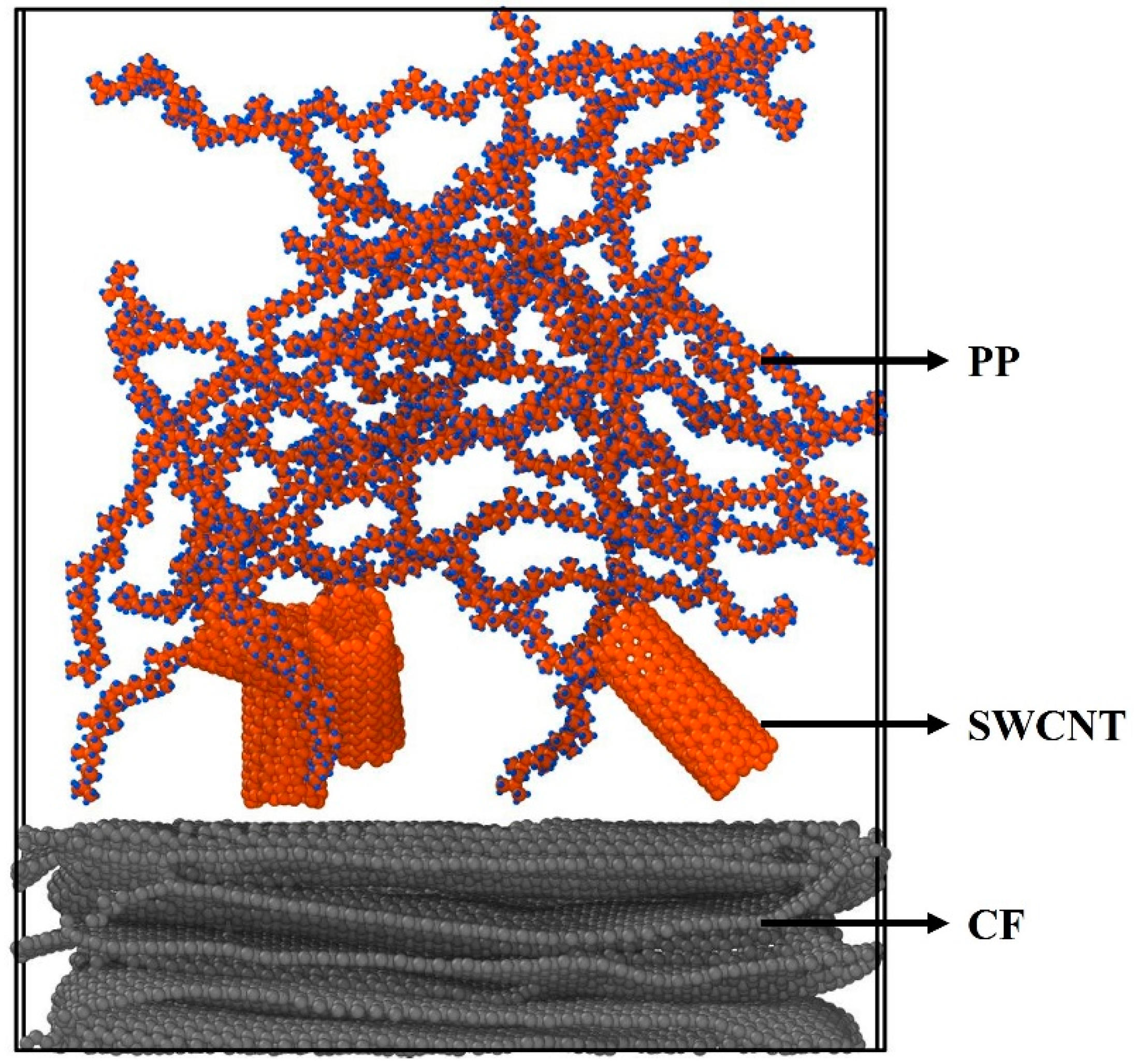
2.1. Model
2.2. Molecular Dynamic Simulations
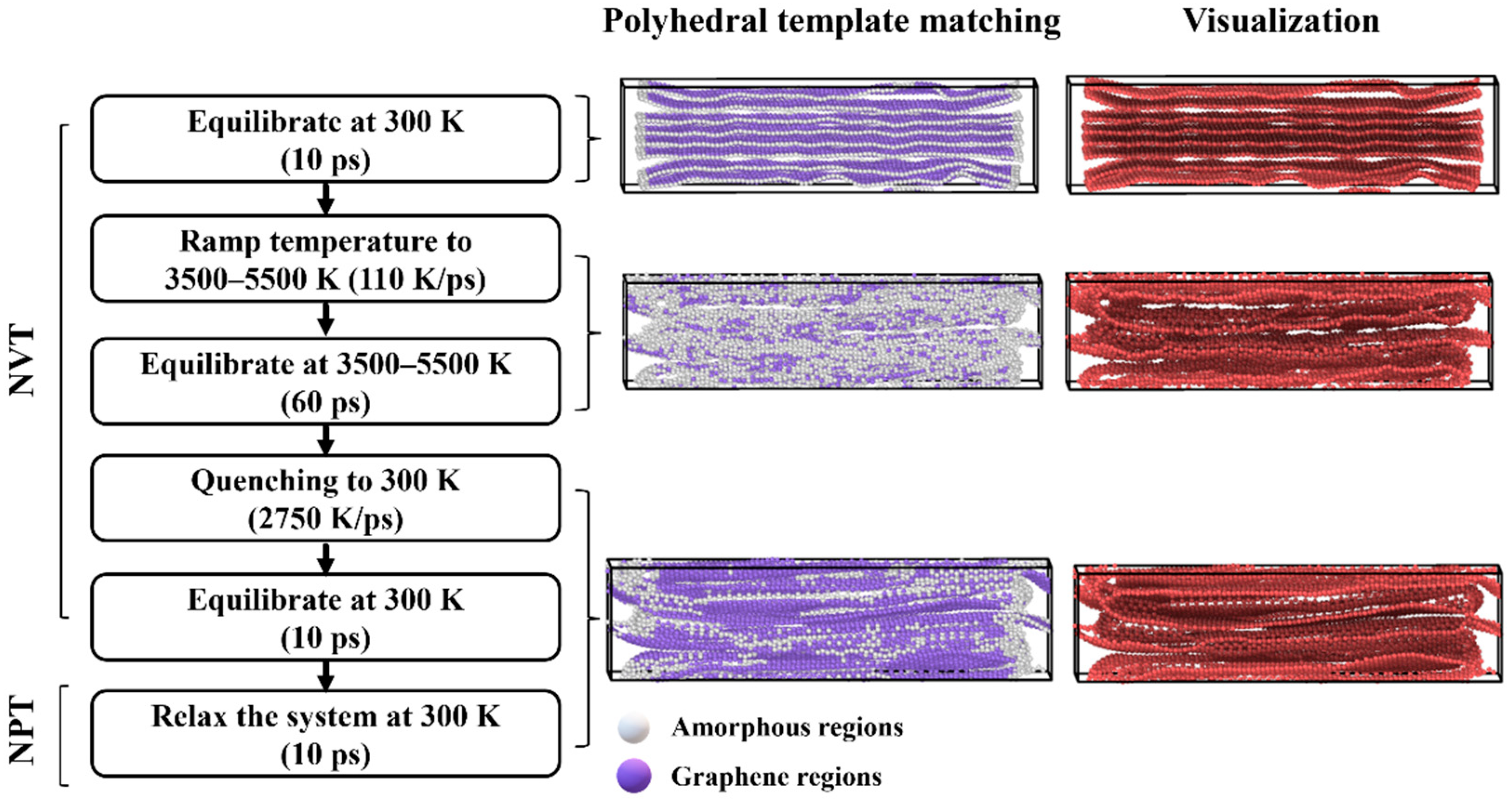
2.2.1. Carbon Fiber Simulation
2.2.2. Uniaxial Stress Simulation
3. Results and Discussions
3.1. Carbon Fiber Model Properties
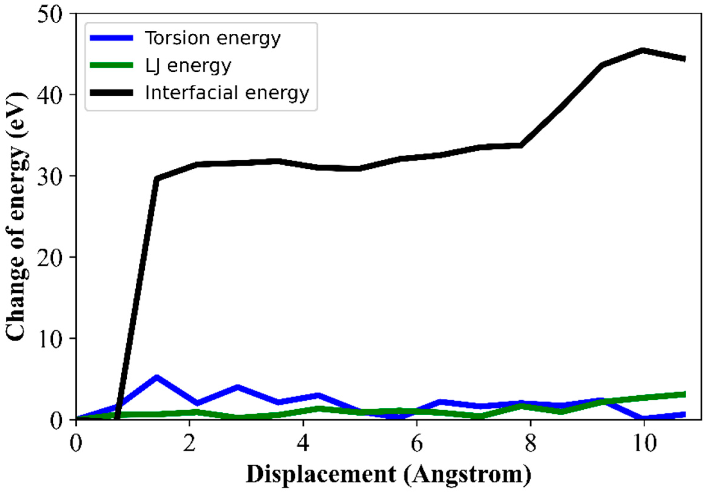
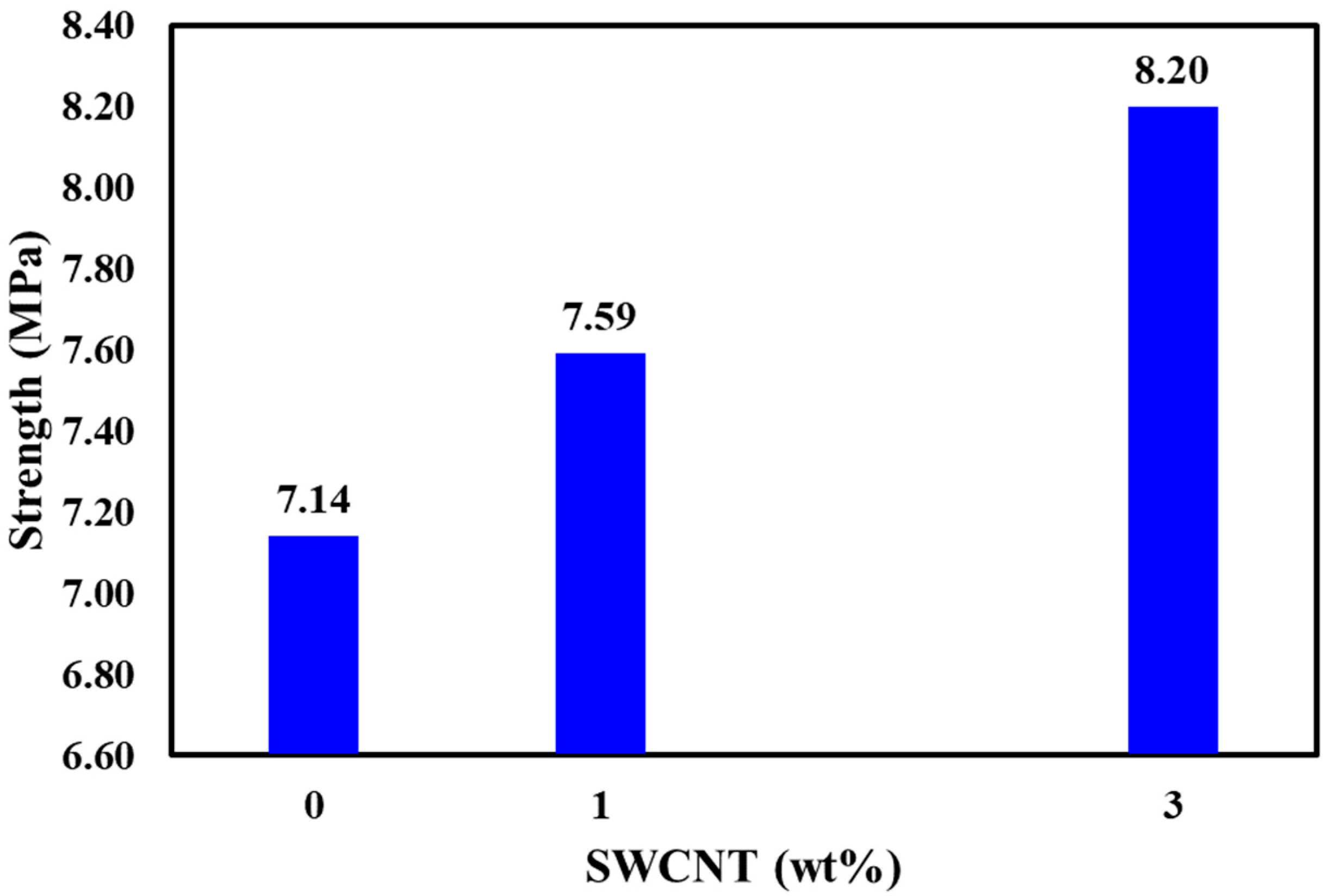
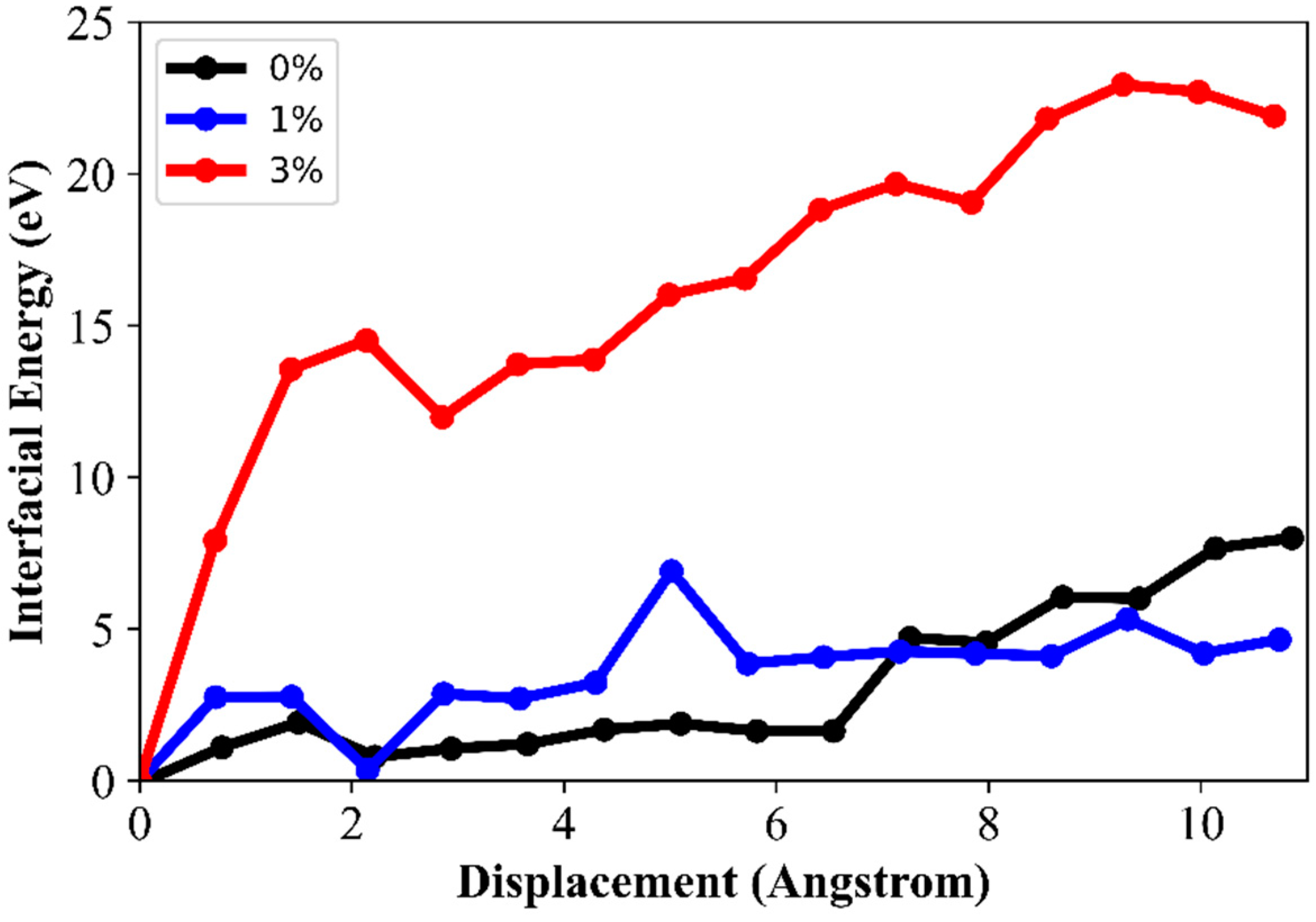
3.2. Nano-Engineered CF Composites Interfacial Properties
4. Conclusions
Supplementary Materials
Author Contributions
Funding
Data Availability Statement
Acknowledgments
Conflicts of Interest
References
- Aizebeokhai, A.P. Global Warming and Climate Change: Realities, Uncertainties and Measures. Int. J. Phys. Sci 2009, 4, 868–879. [Google Scholar] [CrossRef]
- Albuquerque, F.D.B.; Maraqa, M.A.; Chowdhury, R.; Mauga, T.; Alzard, M. Greenhouse Gas Emissions Associated with Road Transport Projects: Current Status, Benchmarking, and Assessment Tools. In Transportation Research Procedia; Elsevier B.V.: Amsterdam, The Netherlands, 2020; Volume 48, pp. 2018–2030. [Google Scholar] [CrossRef]
- Windisch, E.; Benezech, V.; Chen, G.; Kauppila, J. Lightening Up: How Less Heavy Vehicles Can Help Cut CO2 Emissions; OECD: Paris, France, 2017. [Google Scholar]
- Newcomb, B.A. Processing, Structure, and Properties of Carbon Fibers. Compos. Part A 2016, 91, 262–282. [Google Scholar] [CrossRef]
- Das, T.K.; Ghosh, P.; Das, N.C. Preparation, Development, Outcomes, and Application Versatility of Carbon Fiber-Based Polymer Composites: A Review. Adv. Compos. Hybrid Mater. 2019, 2, 214–233. [Google Scholar] [CrossRef]
- Kyriakides, S.; Arseculeratne, R.; Perry, E.J.; Liechti, K.M. On the compressive failure of fiber reinforced composites. Int. J. Solids Structures 1995, 32, 689–738. [Google Scholar] [CrossRef]
- Imani Yengejeh, S.; Kazemi, S.A.; Öchsner, A. Carbon Nanotubes as Reinforcement in Composites: A Review of the Analytical, Numerical and Experimental Approaches. Comput. Mater. Sci. 2017, 136, 85–101. [Google Scholar] [CrossRef]
- Clancy, A.J.; Anthony, D.B.; de Luca, F. Metal Mimics: Lightweight, Strong, and Tough Nanocomposites and Nanomaterial Assemblies. ACS Appl. Mater. Interfaces 2020, 12, 15955–15975. [Google Scholar] [CrossRef]
- Zhao, J.; Liu, L.; Guo, Q.; Shi, J.; Zhai, G.; Song, J.; Liu, Z. Growth of Carbon Nanotubes on the Surface of Carbon Fibers. Carbon 2008, 46, 380–383. [Google Scholar] [CrossRef]
- Bekyarova, E.; Thostenson, E.T.; Yu, A.; Kim, H.; Gao, J.; Tang, J.; Hahn, H.T.; Chou, T.W.; Itkis, M.E.; Haddon, R.C. Multiscale Carbon Nanotube-Carbon Fiber Reinforcement for Advanced Epoxy Composites. Langmuir 2007, 23, 3970–3974. [Google Scholar] [CrossRef]
- Qian, H.; Greenhalgh, E.S.; Shaffer, M.S.P.; Bismarck, A. Carbon Nanotube-Based Hierarchical Composites: A Review. J. Mater. Chem. 2010, 20, 4751–4762. [Google Scholar] [CrossRef]
- Peng, Q.; Meng, F.; Yang, Y.; Lu, C.; Deng, H.; Wang, L.; De, S.; Gao, F. Shockwave Generates <100> Dislocation Loops in Bcc Iron. Nat. Commun. 2018, 9, 4880. [Google Scholar] [CrossRef]
- Deng, B.; Hou, J.; Zhu, H.; Liu, S.; Liu, E.; Shi, Y.; Peng, Q. The Normal-Auxeticity Mechanical Phase Transition in Graphene. 2D Materials 2017, 4, 021020. [Google Scholar] [CrossRef]
- Hou, J.; Deng, B.; Zhu, H.; Lan, Y.; Shi, Y.; De, S.; Liu, L.; Chakraborty, P.; Gao, F.; Peng, Q. Magic Auxeticity Angle of Graphene. Carbon 2019, 149, 350–354. [Google Scholar] [CrossRef] [Green Version]
- Rapaport, D.C. The Art of Molecular Dynamics Simulation, 2nd ed.; Cambridge University Press: Cambridge, UK, 2004. [Google Scholar]
- Ritschl, F.; Fait, M.; Fiedler, K.; Khler, J.E.H.; Kubias, B.; Meisel, M. An Extension of the Consistent Valence Force Field (CVFF) with the Aim to Simulate the Structures of Vanadium Phosphorus Oxides and the Adsorption of n-Butane and of 1-Butene on Their Crystal Planes. Z. Anorg. Allg. Chem. 2002, 628, 1385–1396. [Google Scholar] [CrossRef]
- Sun, H. Ab Initio Calculations and Force Field Development for Computer Simulation of Polysilanes. Macromolecules 1995, 28, 701–712. [Google Scholar] [CrossRef]
- Sun, H. Compass: An Ab Initio Force-Field Optimized for Condensed-Phase Applications—Overview with Details on Alkane and Benzene Compounds. J. Phys. Chem. B 1998, 102, 7338–7364. [Google Scholar] [CrossRef]
- Van Duin, A.C.T.; Dasgupta, S.; Lorant, F.; Goddard, W.A. ReaxFF: A Reactive Force Field for Hydrocarbons. J. Phys. Chem. A 2001, 105, 9396–9409. [Google Scholar] [CrossRef] [Green Version]
- Allington, R.D.; Attwood, D.; Hamerton, I.; Hay, J.N.; Howlin, B.J. A Model of the Surface of Oxidatively Treated Carbon Fibre Based on Calculations of Adsorption Interactions with Small Molecules. Compos. Part A 1998, 29, 1283–1290. [Google Scholar] [CrossRef]
- Allington, R.D.; Attwood, D.; Hamerton, I.; Hay, J.N.; Howlin, B.J. Developing Improved Models of Oxidatively Treated Carbon Fibre Surfaces, Using Molecular Simulation. Compos. Part A 2004, 35, 1161–1173. [Google Scholar] [CrossRef]
- Awan, I.S.; Xiaoqun, W.; Pengcheng, H.; Shanyi, D. Developing an Approach to Calculate Carbon Fiber Surface Energy Using Molecular Simulation and Its Application to Real Carbon Fibers. J. Compos. Mater. 2012, 46, 707–715. [Google Scholar] [CrossRef]
- Penev, E.S.; Artyukhov, V.I.; Yakobson, B.I. Basic Structural Units in Carbon Fibers: Atomistic Models and Tensile Behavior. Carbon 2015, 85, 72–78. [Google Scholar] [CrossRef]
- Rajabpour, S.; Mao, Q.; Gao, Z.; Khajeh Talkhoncheh, M.; Zhu, J.; Schwab, Y.; Kowalik, M.; Li, X.; van Duin, A.C.T. Low-Temperature Carbonization of Polyacrylonitrile/Graphene Carbon Fibers: A Combined ReaxFF Molecular Dynamics and Experimental Study. Carbon 2021, 174, 345–356. [Google Scholar] [CrossRef]
- Zhu, J.; Gao, Z.; Kowalik, M.; Joshi, K.; Ashraf, C.M.; Arefev, M.I.; Schwab, Y.; Bumgardner, C.; Brown, K.; Burden, D.E.; et al. Unveiling Carbon Ring Structure Formation Mechanisms in Polyacrylonitrile-Derived Carbon Fibers. ACS Appl. Mater. Interfaces 2019, 11, 42288–42297. [Google Scholar] [CrossRef] [PubMed]
- Haley, B.; Wilson, N.; Li, C.; Arguelles, A.; Jaramillo, E.; Strachan, A. Polymer Modeler. 2010. Available online: https://nanohub.org/resources/polymod (accessed on 14 June 2021).
- Humphrey, W.; Dalke, A.; Schulten, K. VMD—Visual Molecular Dynamics. J. Molec. Graphics 1996, 14, 33–38. [Google Scholar] [CrossRef]
- Anthony, D.B.; Sui, X.M.; Kellersztein, I.; de Luca, H.G.; White, E.R.; Wagner, H.D.; Greenhalgh, E.S.; Bismarck, A.; Shaffer, M.S.P. Continuous Carbon Nanotube Synthesis on Charged Carbon Fibers. Compos. Part A 2018, 112, 525–538. [Google Scholar] [CrossRef]
- Rouhi, S.; Alizadeh, Y.; Ansari, R. Molecular Dynamics Simulations of the Interfacial Characteristics of Polypropylene/Single-Walled Carbon Nanotubes. Proc. IMechE Part L J. Mater. Des. Appl. 2016, 230, 190–205. [Google Scholar] [CrossRef]
- Martinez, L.; Andrade, R.; Birgin, E.G.; Martínez, J.M. PACKMOL: A Package for Building Initial Configurations for Molecular Dynamics Simulations. J. Comput. Chem. 2009, 30, 2157–2164. [Google Scholar] [CrossRef]
- Stukowski, A. Visualization and Analysis of Atomistic Simulation Data with OVITO-the Open Visualization Tool. Modelling Simul. Mater. Sci. Eng. 2010, 18, 015012. [Google Scholar] [CrossRef]
- Plimpton, S. Fast Parallel Algorithms for Short-Range Molecular Dynamics. J. Comput. Phys. 1995, 117, 1–19. [Google Scholar] [CrossRef] [Green Version]
- Tersoff, J. Empirical Interatomic Potential for Carbon, with Applications to Amorphous Carbon. Phys. Rev. Lett. 1988, 61, 2879–2882. [Google Scholar] [CrossRef] [Green Version]
- O’Connor, T.C.; Andzelm, J.; Robbins, M.O. AIREBO-M: A Reactive Model for Hydrocarbons at Extreme Pressures. J. Chem. Phys. 2015, 142, 024903. [Google Scholar] [CrossRef]
- Grantab, R.; Shenoy, V.B.; Ruoff, R.S. Anomalous Strength Characteristics of Tilt Grain Boundaries in Graphene. Science 2010, 330, 946–948. [Google Scholar] [CrossRef] [Green Version]
- Wei, Y.; Wu, J.; Yin, H.; Shi, X.; Yang, R.; Dresselhaus, M. The Nature of Strength Enhancement and Weakening by Pentagong-Heptagon Defects in Graphene. Nat. Mater. 2012, 11, 759–763. [Google Scholar] [CrossRef]
- Huhtala, M.; Krasheninnikov, A.V.; Aittoniemi, J.; Stuart, S.J.; Nordlund, K.; Kaski, K. Improved Mechanical Load Transfer between Shells of Multiwalled Carbon Nanotubes. Phys. Rev. B 2004, 70, 045404. [Google Scholar] [CrossRef] [Green Version]
- Zhu, C.; Liu, X.; Yu, X.; Zhao, N.; Liu, J.; Xu, J. A Small-Angle X-Ray Scattering Study and Molecular Dynamics Simulation of Microvoid Evolution during the Tensile Deformation of Carbon Fibers. Carbon 2012, 50, 235–243. [Google Scholar] [CrossRef]
- Hoover, W.G. Canonical Dynamics: Equilibrium Phase-Space Distributions. Phys. Rev. A 1985, 31, 1695–1697. [Google Scholar] [CrossRef] [Green Version]
- Carbon Fiber. Toray Composite Materials America, Inc. Available online: https://www.toraycma.com/products/carbon-fiber/ (accessed on 30 July 2021).
- Tse-Hao, K.; Tzy-Chin, D.; Jeng-An, P.; Ming-Fong, L. The Characterization of PAN-Based Carbon Fibers Developed by Two-Stage Continuous Carbonization. Carbon 1993, 31, 765–771. [Google Scholar] [CrossRef]
- Zhu, C.Z.; Yu, X.L.; Liu, X.F.; Mao, Y.Z.; Liu, R.G.; Zhao, N.; Zhang, X.L.; Xu, J. 2D SAXS/WAXD Analysis of Pan Carbon Fiber Microstructure in Organic/Inorganic Transformation. Chin. J. Polym. Sci. 2013, 31, 823–832. [Google Scholar] [CrossRef]
- Thostenson, E.T.; Li, W.Z.; Wang, D.Z.; Ren, Z.F.; Chou, T.W. Carbon Nanotube/Carbon Fiber Hybrid Multiscale Composites. J. Appl. Phys. 2002, 91, 6034–6037. [Google Scholar] [CrossRef]
- Yumitori, S.; Arao, Y.; Tanaka, T.; Naito, K.; Tanaka, K.; Katayama, T. Increasing the Interfacial Strength in Carbon Fiber/Polypropylene Composites by Growing CNTs on the Fibers. Comput. Methods Exp. Meas. XVI 2013, 55, 275–284. [Google Scholar] [CrossRef] [Green Version]
- Zhang, Z.Q.; Ward, D.K.; Xue, Y.; Zhang, H.W.; Horstemeyer, M.F. Interfacial Characteristics of Carbon Nanotube-Polyethylene Composites Using Molecular Dynamics Simulations. ISRN Mater. Sci. 2011, 2011, 145042. [Google Scholar] [CrossRef] [Green Version]


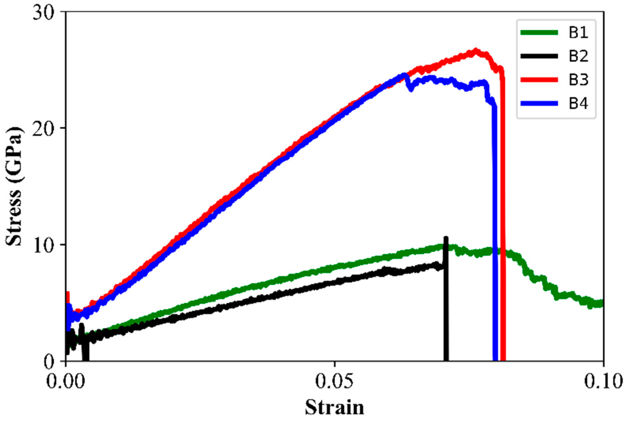
| Model | Annealing Temperature (K) | Number of Carbon Atoms | Density (g/cm3) | Graphene Region (%) | Strength (GPa) | Young’s Modulus (GPa) |
|---|---|---|---|---|---|---|
| B1 | 5500 | 15,739 | 1.64 | 70 | 9.9 | 138.1 |
| B2 | 4500 | 15,739 | 1.63 | 71 | 10.5 | 129.6 |
| B3 | 3500 | 16,120 | 1.68 | 84 | 26.7 | 277.0 |
| B4 | 4500 | 16,120 | 1.69 | 85 | 24.6 | 261.0 |
Publisher’s Note: MDPI stays neutral with regard to jurisdictional claims in published maps and institutional affiliations. |
© 2022 by the authors. Licensee MDPI, Basel, Switzerland. This article is an open access article distributed under the terms and conditions of the Creative Commons Attribution (CC BY) license (https://creativecommons.org/licenses/by/4.0/).
Share and Cite
Almousa, H.; Peng, Q.; Alsayoud, A.Q. A Molecular Dynamics Study of the Stability and Mechanical Properties of a Nano-Engineered Fuzzy Carbon Fiber Composite. J. Compos. Sci. 2022, 6, 54. https://doi.org/10.3390/jcs6020054
Almousa H, Peng Q, Alsayoud AQ. A Molecular Dynamics Study of the Stability and Mechanical Properties of a Nano-Engineered Fuzzy Carbon Fiber Composite. Journal of Composites Science. 2022; 6(2):54. https://doi.org/10.3390/jcs6020054
Chicago/Turabian StyleAlmousa, Hassan, Qing Peng, and Abduljabar Q. Alsayoud. 2022. "A Molecular Dynamics Study of the Stability and Mechanical Properties of a Nano-Engineered Fuzzy Carbon Fiber Composite" Journal of Composites Science 6, no. 2: 54. https://doi.org/10.3390/jcs6020054
APA StyleAlmousa, H., Peng, Q., & Alsayoud, A. Q. (2022). A Molecular Dynamics Study of the Stability and Mechanical Properties of a Nano-Engineered Fuzzy Carbon Fiber Composite. Journal of Composites Science, 6(2), 54. https://doi.org/10.3390/jcs6020054