1. Introduction
Efforts to reduce environmentally harmful emissions and the increasingly holistic approach towards the consideration of the entire component life cycle from manufacture to disposal (life cycle assessment) increase the pressure on material and production processes developments. Particularly in the area of fiber reinforced plastics, the development focus must not be exclusively on mechanical performance and cycle times. For example, the superior specific properties of carbon fiber-reinforced plastic (CFRP) structures and the weight and emission savings they offer are offset by significantly higher resource consumption during material extraction (greenhouse gas impact of 38.9 kg CO
2-equivalent per kg CF [
1]) and component manufacture. This burden at the beginning of the product life cycle must be reduced, especially when carbon fibers are used, in order to achieve an advantage over conventional materials when balancing the entire component life cycle.
One way to achieve this goal is to reduce the use of CO
2 intensive materials. Sandwich design is a suitable strategy for reducing the amount of carbon fibers, especially for large and flat components. The geometric stiffening effect is utilized for components subjected to bending and buckling loads by increasing the area moment of inertia in the relevant cross-section. Transferred to highly stressed CFRP components, continuous fiber-reinforced face sheets in combination, with a lightweight foam core, are an optimal combination for lightweight designs [
2,
3,
4]. The concept of sandwich panels is already widely used in several fields of application, especially within the construction and building sector [
5]. Besides CF reinforcements, glass and flax fiber reinforcements are also within the focus of current research activities, e.g., for cladding wall panels [
6,
7,
8].
In addition to the reduced use of materials, the manufacturing process also needs to made more efficient. Traditionally, pre-fabricated foam cores are processed together with fiber-reinforced cover layers. The cover layers can either consist of pre-impregnated material (so-called prepreg) [
9], or they can be impregnated during the component manufacturing process [
10,
11]. However, this is at least a two-stage process, since the pressure-sensitive foam core needs to be provided by a preceding manufacturing step. For increasing production efficiency, some one-step sandwich manufacturing approaches are already developed and described in the literature.
M. Ware developed the Thermal Expansion RTM (TERTM), a manufacturing process for fiber-reinforced sandwich structures using internal pressure generated by the foam core. However, this is still a two-stage process by which a PUR or PI foam core is wrapped with reinforcing material, placed in a cold mold and matrix material is injected. By controlled the heating of the mold, the thermal expansion of the foam core leads to an improved impregnation of the fabric material [
12,
13].
For one-step sandwich fabrication, Hopmann et al. developed a process that uses a syntactic foam system. They use polymeric hollow microspheres loaded with a low-boiling liquid as blowing agent. Mixed in an epoxy resin system, the polymeric hollow microsphere shell becomes flexible under the heat of the heated mold, and the transition of the low-boiling liquid into gas phase leads to the expansion of the blowing particles. To produce a sandwich structure, glass fiber textiles serve as filters in the sandwich face sheets. Used in a wet pressing process, the hollow microspheres of the syntactic foam system do not penetrate the textile reinforcement structure. The expanding microspheres force the matrix system into the textile fabric and thus leading to the impregnation of the face sheets. The cured matrix material fixates the expanded hollow spheres, which remain as foam pores in the material (achieved densities: 530–720 g/L) [
14,
15].
Weißenborn et al. developed a one-step process for the production of sandwich structures by using the expansion reaction of foamable polyurethane (PUR) in a closed mold. The reactive PUR mixture forms both the foam core and the matrix material for the textile reinforcement in the sandwich face sheets. Consequently, the foam core and the sandwich face sheets are produced in a single step and with the same material. The pore content in the top layer can be influenced by manipulating the pressure conditions during the process. The foam achieved densities range from 270 to 770 g/L, and a maximum roving impregnation of 84% was observed for CF fabric [
16].
Hopmann et al. developed an additional one-step process for the production of fiber-reinforced sandwich structures, based on two independent material systems for the foam core and the face sheets. A non-foamable PUR material is applied on the face sheet textile outside of the mold, targeting 38% fiber volume content (FVC). The pre-impregnated face sheets are then combined with a reactive PUR foam system in a mold. Utilizing the expansion reaction of the foamable component, the face sheets are pressed against the cavity wall, consolidated and cured. The sandwich structures produced have foam densities ranging from 397.4 g/L to 592.8 g/L, the resulting FVC was not determined [
17].
The basic idea of the intended process strategy is to use the pressure occurring during the PUR foam reaction for fiber impregnation and consolidation of the top layers. Following the example of Hopmann et al. [
17] two independent material systems will be used for the foam core and the face sheet material. However, the target process is distinguished from Hopmann’s approach by the use of an impermeable boundary layer (polymer film) between the face sheets and the reactive foam system. This leads to a higher flexibility regarding the resin types for the face sheets (e.g., use of epoxy based systems) and prevents an uncontrollable penetration of the foam system into the face sheets resulting in locally increased porosity.
This paper focuses on the material characterization and development as a basis for the described direct sandwich composite molding (D-SCM) process approach. Based on the current state of scientific knowledge the PUR system was identified as the key component during implementation of the D-SCM process. Therefore, an optimized PUR foam system has been developed, and described in this paper, in order to increase the light-weighting potential of the structures by lowering the foam density and increasing the FVC of the face sheets. The PUR material system development for novel process variants requires boundaries that need to be identified. For this reason, the compaction and the rheological behavior of the face sheet materials are also presented within this paper. The curing characteristics of the matrix material for the face sheets define the necessary reaction speed for the PUR foam system (foaming pressure needs to be applied before the matrix system in the face sheets is cured) and the compaction behavior of the fabric indicates the necessary maximum foaming pressure to achieve certain FVC. Based on this investigation, the theoretical suitability of the developed foam system is discussed and evaluated. The paper will conclude with a preliminary process strategy, based on the determined individual material characteristics. The actual realization of the one-step process is the subject of further work and will not be considered within this publication.
Figure 1 shows the idealized steps of D-SCM process. A resin pre-infiltrated textile layer (green) plus polymer film (red) is placed in the heated mold, (1) the reactive polyurethane foam mixture is introduced into the cavity, and (2) a second pre-infiltrated textile layer plus polymer film forms the upper face sheet (3). The mold closes to the target component thickness, and (4) the expansion reaction of the foam builds up pressure on the outer face sheet layers (5). This internal pressure completes the impregnation, followed by the subsequent consolidation (curing) of the cover layers (6). After curing, the mold can be opened and the sandwich structure removed (7).
The described D-SCM process offers a high potential for industrial applications. Considering the state of the art process variants with pre-cut and three-dimensional (3D)-milled foam cores, scrap rates of up to 90% for complex geometries can be avoided. Furthermore, the processing equipment costs may be reduced as the D-SCM process variant utilizes equally distributed low pressures. Expensive hydraulic press equipment is not necessary.
The process development within this paper is considered with carbon fibers as reinforcement material to achieve the highest lightweight potential. Glass fibers can be an adequate alternative, in terms of cost efficiency. The targeted D‑SCM process provides the potential for substituting the fiber material, in the future, to open up further fields of applications.
3. Results
3.1. Rheology of the Face Sheet Resin Systems
Figure 4 shows the determined viscosity behavior over time for both epoxy resin systems at 80 °C up to 1000 mPa·s. It is obvious that the Epikote system has a lower reaction speed than the Araldite system. The time to reach a viscosity of 500 mPa·s is ~120 s for Araldite and ~260 s for the Epikote system. Both materials show a slight temperature-dependent decrease in viscosity in the beginning of the tests, which is then overcome by the crosslinking reaction of the polymer that leads to an increasing viscosity during curing. For the Epikote material, this results in a comparatively long time below 100 mPa·s of about 140 s against the Araldite system.
The significantly different viscosity over time characteristics for both systems allowed us to analyze the face sheet resin viscosity influence on the D-SCM process. It is assumed that a resin viscosity above 500 mPa·s leads to an insufficient impregnation quality. For the polyurethane foam system development, this assumption resulted in a requirement for the foaming-speed, as the maximum foaming pressure should be reached before the resin systems pass the 500 mPa·s limit to ensure high quality impregnation.
3.2. Compaction Analysis of the Face Sheet Fabric Material
The diagrams in
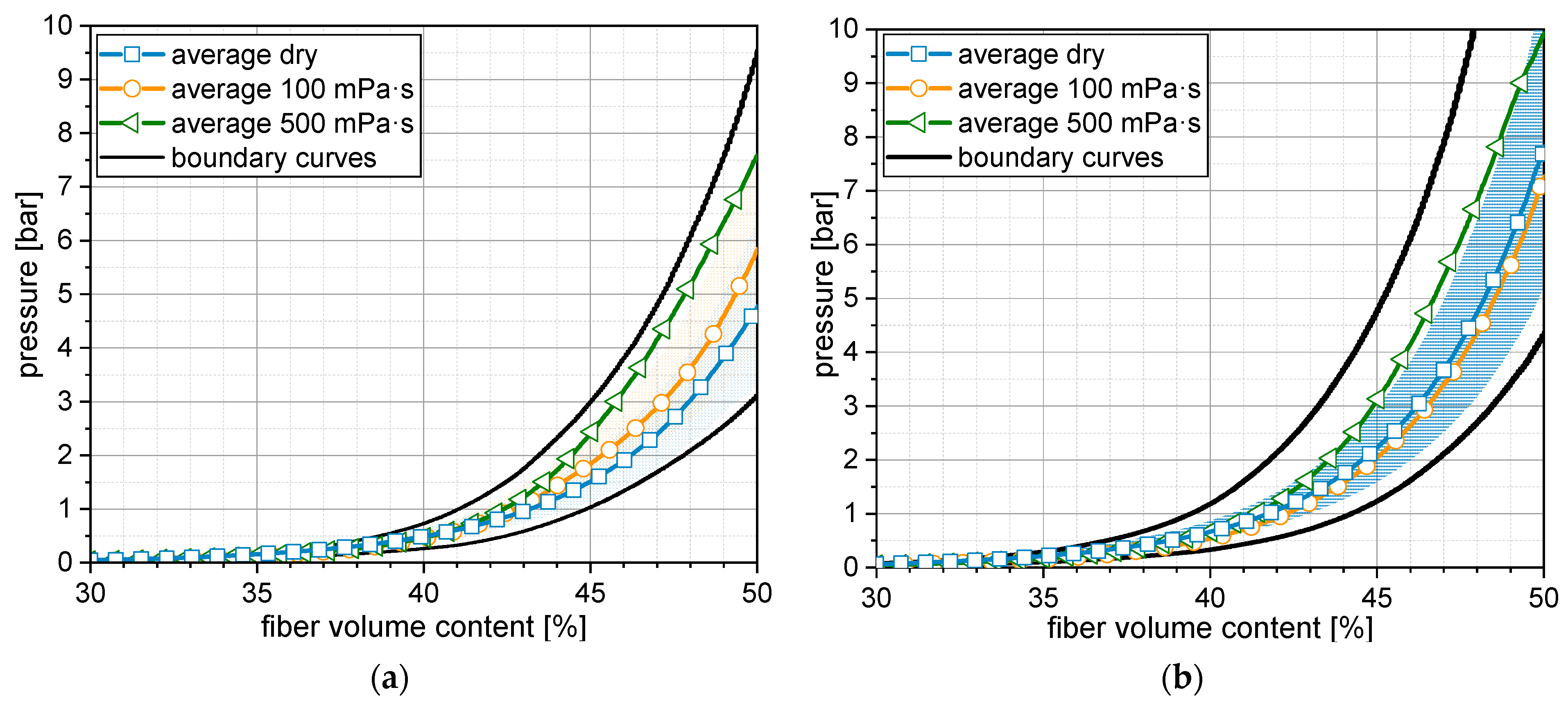
Figure 5 shows the resulting average pressure values related to the FVC with the corresponding standard deviation, illustrated as enveloping surface. The boundary curves represent the highest and lowest pressure to FVC ratios, observed during all compaction tests per configuration.
The configuration in
Figure 5a (C1 configuration) shows a dependency of the necessary pressure for compacting the fabric to a certain FVC on the impregnation situation. The average pressure curves increase from dry fabric over 100 mPa·s to 500 mPa·s. This effect is due to the necessary additional pressure to enable the fluid flow (fluid pressure) during the compaction trial in case the fabric is impregnated, also investigated by Poppe et al. [
22]. The higher the viscosity the higher the necessary additional pressure. It must be mentioned that this effect is valid for the average pressure values, but the enveloping surfaces representing the standard deviation overlap and the effect, is thus, not generally valid. A similar behavior can be observed in
Figure 5b (C2 configuration) from dry fabric to 500 mPa·s. The average values for 100 mPa·s are slightly lower than for dry fabric and very close to each other. In general, the C2 configuration shows higher necessary pressures to achieve a certain FVC. This is due to the different surface textures of the 50 K based CF fabric. On the straight stitching side of the fabric, the 50 K rovings were subdivided into smaller fiber bundles by the stitching yarn (see
Figure 2b). This resulted in a smoother surface compared to the zick-zack side. As the compaction was characterized by only using two layers of fabric, singularities like local fiber accumulations could not be homogenized using thickness direction. These singularities are less likely if the surfaces within the symmetry plane are smoother like for the C1-configuration and thus the necessary compaction pressure is lower. The effect of the local singularities partially superimposes and blurs the viscosity influence on the compaction behavior for the C2 configuration. The C1 configuration is preferable for the D-SCM process as less pressure is needed for the face sheet compaction and thus higher FVC are achievable.
3.3. Reactive Polyurethane Foam System Development
The design analysis of the performed FCCCD-based DoE shows an R-square of 99.53% and an adjusted R-square of 99.39%, and is thus, considered valid for well-founded conclusions on the material characteristics. The main effects plot for the influence of the factors water portion, catalyst portion and foam density on the maximum foam pressure is shown in
Figure 6. We observed that the higher the gradient of the curve, the higher the influence of the factor on the maximum foam pressure.
The water portion effect on the mean of the maximum foaming pressure is almost linear and rises from 2.1 bar monotonously to 3.6 bar at higher water contents. This behavior was expected as more CO2 molecules can be generated by the reaction of isocyanate and water which results in a higher pressure inside the closed cavity. A similar, but even more significant influence is the foam density on the maximum foam pressure (1.7–4.1 bar). This effect is explained by the decreasing free volume and increasing absolute water content as soon as the amount of reactive material is increased with higher foam densities. Both aspects work in the same direction towards a higher internal cavity pressure. The catalyst portion has a qualitatively analogous influence on the pressure (higher catalyst portion → higher pressure), but the function is slightly quadratic and less significant (2.9–3.1 bar). The foaming behavior of the polyurethane system is always a combination of the CO2-reaction and the crosslinkage of the polymer network. The catalyst influences both heat-dependent reactions. However, it seems that the crosslinkage at lower catalyst portions of 0.5 and the accompanying viscosity increase prevents the foam system from developing the full blowing potential. With higher catalyst portions, the CO2-reaction can keep pace with the polymerization and thus reach higher cavity pressures.
With regard to the foam system development for the D-SCM process, a high maximum pressure for the foam formulation is preferred. It is obvious, that the maximum water portion of 3.1, and catalyst portion of 1.1, respectively should be considered for the formulation of the foaming polyurethane system. However, both factors also lead to an accelerated foaming reaction, which might be challenging for the necessary overall process. If the material reaction is too fast and the mold cannot be closed completely before the foam expands, leakages could occur or the foam structure can be affected negatively.
The density is a powerful adjusting lever for the maximum pressure. However, a higher density works against the superior goal of a lightweight design. In this context, the lowest possible density for achieving the desired component properties should be targeted for the D-SCM process development.
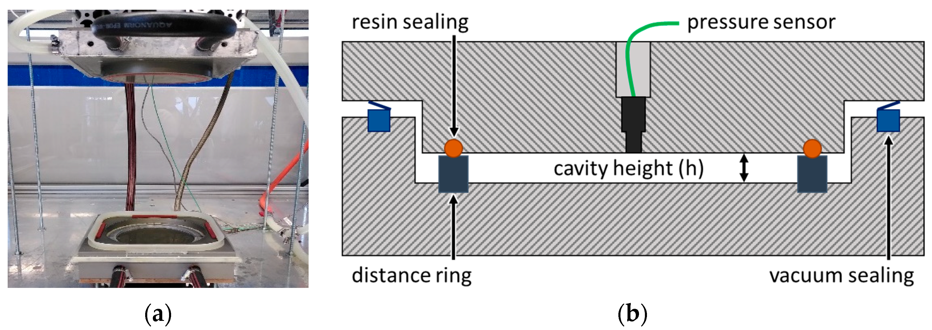
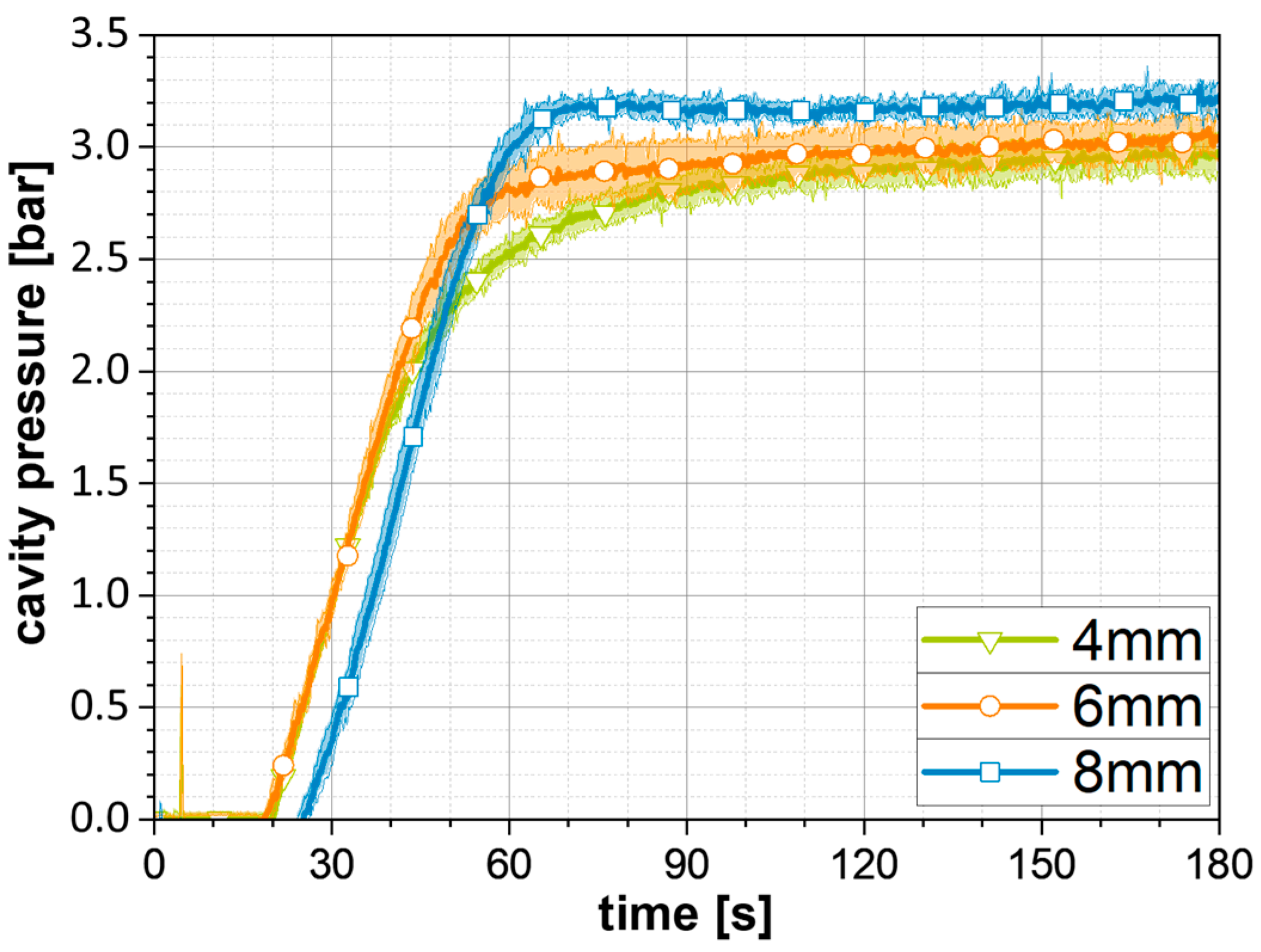
Besides the system formulation and the density-impact on the cavity pressure, the influence of the cavity height was investigated. The foam configuration was kept constant at 162.8 g/L ± 3.2 density (target: 160 g/L, see
Table 1), 3.1 parts water and 1.1 parts catalyst. The resulting pressure curves (average curve and standard deviation as enveloping surface) are shown in
Figure 7.
At 4 mm cavity height, the pressure increase starts after 19 s, is nearly linear until 1.8 bar, and then flattens out considerably towards the maximum pressure close to 3 bar at 180 s. The trials at 6 mm show a similar pressure increase rate rise after 19 s. The linear part of the curve rises up to 2.4 bar and then flattens sharper than the 4 mm curve towards the maximum pressure just above 3 bar. This effect is even more pronounced at 8 mm cavity height. The pressure increase starts at 25 s and the gradient is similar to the 4 and 6 mm curves. However, the linear pressure rise ends comparably sharp into a plateau at around 3.2 bar. The late start of the curve at 8 mm height can be explained by the longer distance for the foam to reach the pressure sensor in the upper mold even as there is more material introduced to ensure the same foam density like for the 4 and 6 mm trials. The foam pressure curve progression at the three investigated heights is mainly driven by the heat introduction into the foaming material. As mentioned, the foaming of the polyurethane system is always a combination of the CO2-reaction and the crosslinkage of the polymer network. The results from the DoE already suggest that the formulation needs a certain amount of catalyst to speed up the CO2-reaction, whereas the crosslinkage is sufficiently driven by the heated mold. By increasing the mold height, the heated cavity surface increases less in relative terms to the cavity volume. Therefore, the energy input into the material at constant mold temperature is reduced on a volume-specific basis. At 4 mm cavity height, the foam material is heated via the mold surface and the crosslinkage reaction is slowing down the foam reaction. For 8 mm cavity height, the energy input through the mold surface into the double amount of material compared to 4 mm (density = constant) is volume-specific lower. Consequently, the crosslinkage reaction is slower and the catalyst-driven CO2-reaction of the foam system can develop the full potential, resulting in higher maximum pressure values.
4. Discussion
The following discussion explains the identification, for the first time, of the theoretical processing windows, based on the individual material characterizations, taking the chronological order of the process steps into account. The realization of the D-SCM process is not part of the paper. The process is dominated by manual process steps for the first investigations. The reactive polyurethane foam mixture is introduced into the cavity 20 s after the first impregnated textile layer plus polymer film (first sheet) is placed in the heated mold (1). The foam application time is estimated with 20 s (2) and the second impregnated textile layer plus polymer film (second sheet) is placed in the mold 10 s after foam application end (3). Twelve second mold closing time is defined within the experimental setup program (4), followed by the system curing and sandwich demolding.
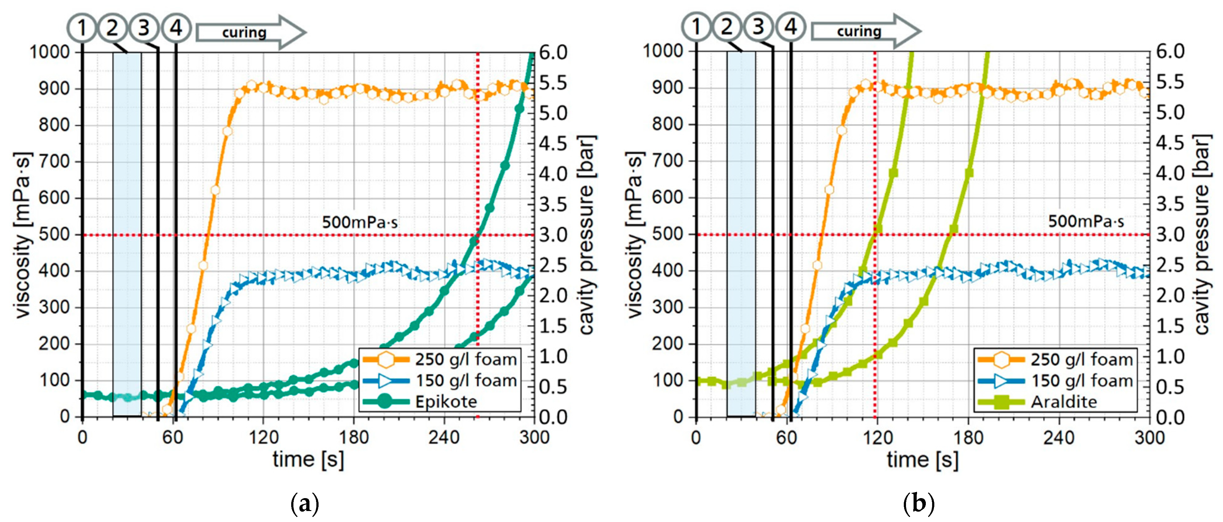
Figure 8 shows exemplary process strategies for both resin systems (
Figure 8a for Araldite,
Figure 8b for Epikote) in the face sheets as well as 150 g/L and 250 g/L foam density, based on the independent material characterization. The resin viscosity is plotted on the left and the expectable foaming pressure on the right
y-axis.
Figure 8a shows two viscosity curves of the Araldite resin system that represent the viscosity increase for the lower (first sheet, starting from 0 s) and the upper face sheet (second sheet, starting from 50 s). The blue area indicates the time for the foam application that ends after 40 s after, which the foam reaction starts. Two different foaming pressure curves are illustrated, one for 250 g/L and one for 150 g/L foam density, whereas the formulation is the same for both curves (3.1 parts water, 1.1 parts catalyst). By sorting the material behaviors along the chronological process chain, potential issues during the one-step process can be identified. As already explained, 500 mPa·s is considered as viscosity limit until when the maximum foaming pressure should be reached. As highlighted by the horizontal dashed line (red) in
Figure 8b, this limit is reached for the lower, and thus, first introduced face sheet at 118 s (vertical dashed line). At this time, the foam curves just reached the maximum pressure plateau with which the combination of the considered foam formulation and the Araldite resin seems to be feasible. However, this needs to be verified during actual one-step sandwich manufacturing trials as the heat transition trough the face sheet material, and thus, the foaming pressure built-up could be slowed down. This could lead to a situation where the resin viscosity of the lower face sheet already passes the 500 mPa·s limit and thus affects the impregnation quality negatively. In that case,
Figure 8a shows an alternative combination where the Epikote resin system is used for the face sheet impregnation by the same foam configurations. The slower viscosity increase leads to more time for the foam expansion as the 500 mPa·s limit is reached only after 262 s. At this point, the maximum foaming pressure is already fully developed, even if a delay due to the heat transfer trough the face sheets occurs. However, the higher process safety by using the Epikote system is a tradeoff towards longer cycle times as the face sheets need to be fully cured before demolding the sandwich. With respect to productivity, this step should be avoided as long as it is not necessary due to quality reasons. For both foam curves in
Figure 8, the time when reaching the maximum pressure plateau and the gradient are comparable. The curve with for 250 g/L foam density rises at an earlier point in time as the applied foam material amount in the same cavity volume is respectively higher. The main advantage by using the 250 g/L configuration is the higher pressure of 5.4 bar compared to 2.3 bar with 150 g/L. When considering the C1 configuration for the face sheet fabric (
Figure 5a, left boundary curve) 5.4 bar results theoretically in 47.5% FVC and the 2.3 bar in 44% FVC. As the sandwich weight is affected by the density increase of the foam core, it must be evaluated on a case-by-case basis whether the higher fiber volume content is worthwhile at a component level. For all the described theoretical considerations, it must be highlighted that their foundation contains independent material characterizations and needs to be verified during realization of the D-SCM process.


