
Numerical Analysis of Filament Wound Cylindrical Composite Pressure Vessels Accounting for Variable Dome Contour


Abstract
1. Introduction
2. Dome Design
2.1. Geodesic Paths
2.2. Non-Geodesic Paths
2.3. Dome Profile Equation
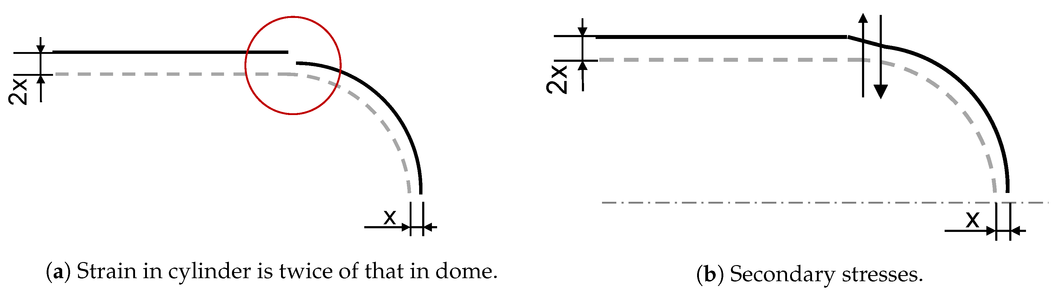
3. Dome-Cylinder Interface
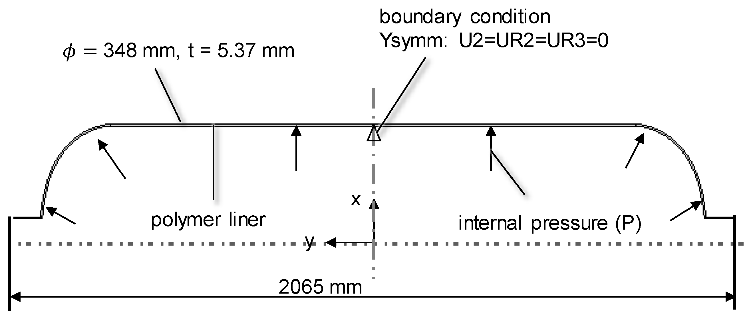
4. Finite Element Model
5. Results
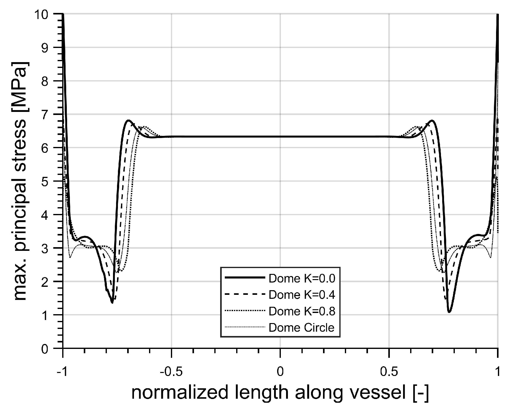
5.1. Liner Analysis
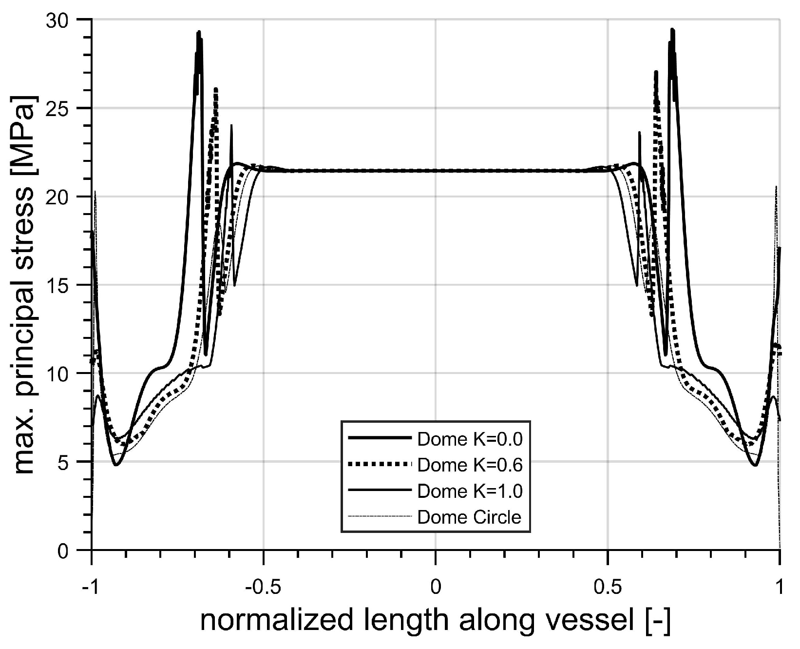
5.2. Composite and Liner Analysis
6. Conclusions
Author Contributions
Funding
Acknowledgments
Conflicts of Interest
References
- Stolten, D.; Emonts, B.; Grube, T. (Eds.) Der 4. DeutscheWasserstoff-Congress 2008—Tagungsband. In Schriften des Forschungszentrums Jülich Reihe Energie & Umwelt; Forschungszentrum Zentralbibliothek: Jülich, Germany, 2008. [Google Scholar]
- Peters, S.T. (Ed.) Composite Filament Winding; ASM International: Materials Park, OH, USA, 2011. [Google Scholar]
- Lengersdorf, M. Produktorientiertes Geflecht-Preforming für Druckbehälter in Faserverbundbauweise. Ph.D. Thesis, RWTH Aachen, Aachen, Germany, 2017. [Google Scholar]
- Askeland, D.R. The Science and Engineering of Materials; Springer: Dordrecht, The Netherlands, 1991. [Google Scholar]
- Tew, B.W. Preliminary Design of Tubular Composite Structures Using Netting Theory and Composite Degradation Factors. J. Press. Vessel Technol. 1995, 117, 390–394. [Google Scholar] [CrossRef]
- Gheshlaghi, R.M.; Hojjati, M.H.; Daniali, H.R.M. Analysis of Composite Pressure Vessels. In Fracture of Nano and Engineering Materials and Structures; Gdoutos, E.E., Ed.; Springer: Dordrecht, The Netherlands, 2006; Volume 117, pp. 335–336. [Google Scholar]
- Zhang, Q.; Xu, H.; Jia, X.; Zu, L.; Cheng, S.; Wang, H. Design of a 70 MPa type IV hydrogen storage vessel using accurate modeling techniques for dome thickness prediction. Compos. Struct. 2020, 236, 111915. [Google Scholar] [CrossRef]
- Mallick, K.; Cronin, J.; Arzberger, S.; Tupper, M.; Grimes-Ledesma, L.; Lewis, J.; Paul, C.; Welsh, J. Ultralight Linerless Composite Tanks for In-Space Applications. In Space 2004 Conference and Exhibit; American Institute of Aeronautics and Astronautics, Ed.; American Institute of Aeronautics and Astronautics: Reston, VA, USA, 2004; p. 121. [Google Scholar]
- Gray, D.; Moser, D. Finite Element Analysis of a Composite Overwrapped Pressure Vessel. In 40th AIAA/ASME/SAE/ASEE Joint Propulsion Conference and Exhibit; American Institute of Aeronautics and Astronautics: Reston, VA, USA, 2004; p. 3506. [Google Scholar]
- Multhoff, J.B.; Krieger, J. Effective structural design procedure for composite hydrogen tanks. In Proceedings of the 18th World Hydrogen Energy Conference 2010—WHEC 2010, Forschungszentrums Jülich, Jülich, 16–21 May 2010; Volume 78-4, ISBN 978-3-89336-654-5. [Google Scholar]
- Magneville, B.; Gentilleau, B.; Villalonga, S.; Nony, F.; Galiano, H. Modeling, parameters identification and experimental validation of composite materials behavior law used in 700 bar type IV hydrogen high pressure storage vessel. Int. J. Hydrog. Energy 2015, 40, 13193–13205. [Google Scholar] [CrossRef]
- Willardson, R.P.; Gray, D.L.; DeLay, T.K. Improvements in FEA of Composite Overwrapped Pressure Vessels. In Proceedings of the Society for the Advancement of Material and Porcess Engineering–Fall Technical Conference, Wichita, KS, USA, 24 April 2009. [Google Scholar]
- Tam, W.H.; Griffin, P.S.; Jackson, A.C. Design and manufacture of a composite overwrapped pressurant tank assembly. In Proceedings of the 38th AIAA/ASME/SAE/ASEE Joint Propulsion Conference & Exhibit, Indianapolis, Indiana, 7–10 July 2002. [Google Scholar]
- Park, Y.H.; Sakai, J. Optimum design of composite pressure vessel structure based on 3-dimensional failure criteria. Int. J. Mater. Form. 2020, 13, 957–965. [Google Scholar] [CrossRef]
- Almeida, J.H.S.; Faria, H.; Marques, A.T.; Amico, S.C. Load sharing ability of the liner in type III composite pressure vessels under internal pressure. J. Reinf. Plast. Compos. 2014, 33, 2274–2286. [Google Scholar] [CrossRef]
- Lin, S.; Yang, L.; Xu, H.; Jia, X.; Yang, X.; Zu, L. Progressive damage analysis for multiscale modelling of composite pressure vessels based on Puck failure criterion. Compos. Struct. 2021, 255, 113046. [Google Scholar] [CrossRef]
- Koussios, S. Filament Winding: A Unified Approach; DUP Science: Delft, The Netherlands, 2004. [Google Scholar]
- Zu, L.; Xu, H.; Wang, H.; Zhang, B.; Zi, B. Design and analysis of filament-wound composite pressure vessels based on non-geodesic winding. Compos. Struct. 2019, 207, 41–52. [Google Scholar] [CrossRef]
- Koussios, S.; Bergsma, O.K. Friction Experiments for Filament Winding Applications. J. Thermoplast. Compos. Mater. 2006, 19, 5–34. [Google Scholar] [CrossRef]
- Hartog, J.P.D. Advanced Strength of Materials; Dover Civil and Mechanical Engineering, Dover Publications: Newburyport, MA, USA, 2014. [Google Scholar]
- Timoshenko, S. Strength of Materials, 3rd ed.; CBS Publishers & Distributors: New Delhi, India, 2002. [Google Scholar]
- Moser, K. Faser-Kunststoff-Verbund: Entwurfs- und Berechnungsgrundlagen; VDI-Buch, Springer: Berlin/Heidelberg, Germany, 1992. [Google Scholar] [CrossRef]
- Barboza Neto, E.S.; Chludzinski, M.; Roese, P.B.; Fonseca, J.; Amico, S.C.; Ferreira, C.A. Experimental and numerical analysis of a LLDPE/HDPE liner for a composite pressure vessel. Polym. Test. 2011, 30, 693–700. [Google Scholar] [CrossRef]
- Dassault Systèmes Simulia Corp. Abaqus 6.14 Documentation; Dassault Systèmes Simulia Corp: Johnston, RI, USA, 2014. [Google Scholar]
- Vasiliev, V.V.; Krikanov, A.A.; Razin, A.F. New generation of filament-wound composite pressure vessels for commercial applications. Compos. Struct. 2003, 62, 449–459. [Google Scholar] [CrossRef]


| Carbon-Epoxy UD—Orthotropic | |||||||
|---|---|---|---|---|---|---|---|
| [MPa] | [MPa] | [-] | [-] | [MPa] | [MPa] | ||
| Carbon Epoxy UD—Orthotropic—Strength | |||||||
| [MPa] | [MPa] | [MPa] | [MPa] | [MPa] | [MPa] | ||
| Liner (LDPE)—Isotropic | |||||||
| [MPa] | [-] | ||||||
| Liner (HDPE)—Isotropic | |||||||
| [MPa] | [-] | ||||||
Publisher’s Note: MDPI stays neutral with regard to jurisdictional claims in published maps and institutional affiliations. |
© 2021 by the authors. Licensee MDPI, Basel, Switzerland. This article is an open access article distributed under the terms and conditions of the Creative Commons Attribution (CC BY) license (http://creativecommons.org/licenses/by/4.0/).
Share and Cite
Jois, K.C.; Welsh, M.; Gries, T.; Sackmann, J. Numerical Analysis of Filament Wound Cylindrical Composite Pressure Vessels Accounting for Variable Dome Contour. J. Compos. Sci. 2021, 5, 56. https://doi.org/10.3390/jcs5020056
Jois KC, Welsh M, Gries T, Sackmann J. Numerical Analysis of Filament Wound Cylindrical Composite Pressure Vessels Accounting for Variable Dome Contour. Journal of Composites Science. 2021; 5(2):56. https://doi.org/10.3390/jcs5020056
Chicago/Turabian StyleJois, Kumar C., Marcus Welsh, Thomas Gries, and Johannes Sackmann. 2021. "Numerical Analysis of Filament Wound Cylindrical Composite Pressure Vessels Accounting for Variable Dome Contour" Journal of Composites Science 5, no. 2: 56. https://doi.org/10.3390/jcs5020056
APA StyleJois, K. C., Welsh, M., Gries, T., & Sackmann, J. (2021). Numerical Analysis of Filament Wound Cylindrical Composite Pressure Vessels Accounting for Variable Dome Contour. Journal of Composites Science, 5(2), 56. https://doi.org/10.3390/jcs5020056