Mechanical Analysis of Flexible Riser with Carbon Fiber Composite Tension Armor


Abstract
1. Introduction
2. Theory and Model
2.1. Theory
2.1.1. Elastic Modulus of Composite Material
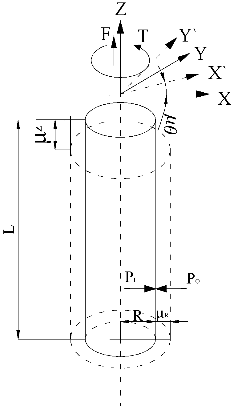
2.1.2. Analytical Model of Unbonded Flexible Riser
2.1.3. Failure Criteria for Composites
2.1.4. Contact Formulation
2.2. Finite Element Model
2.2.1. Model Parameters
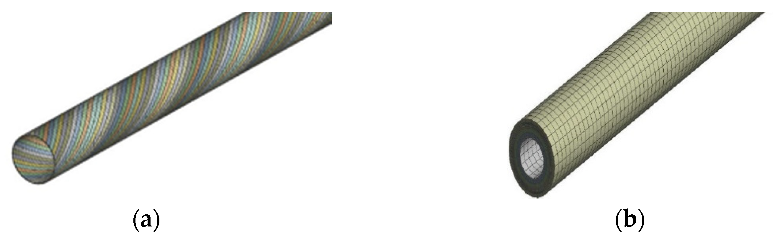
2.2.2. Flexible Riser Model
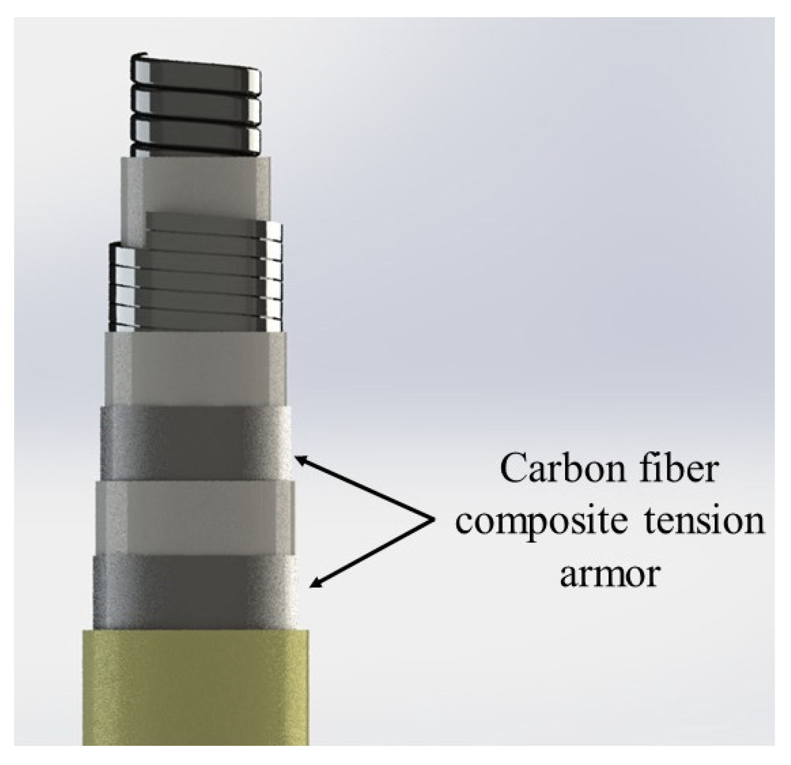
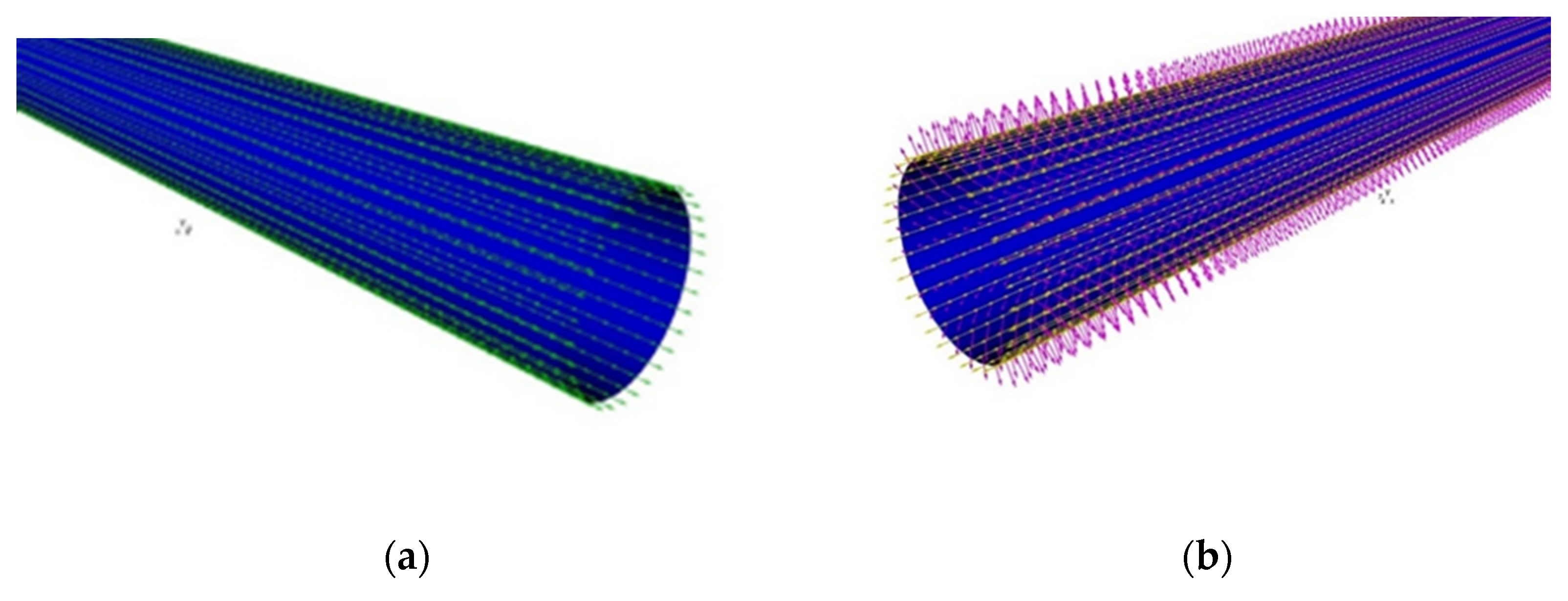
2.2.3. Composite Tension Armor
2.2.4. Contact
2.2.5. Boundary Conditions and Load
3. Results
3.1. The Composite Lamination of the Tensile Armor
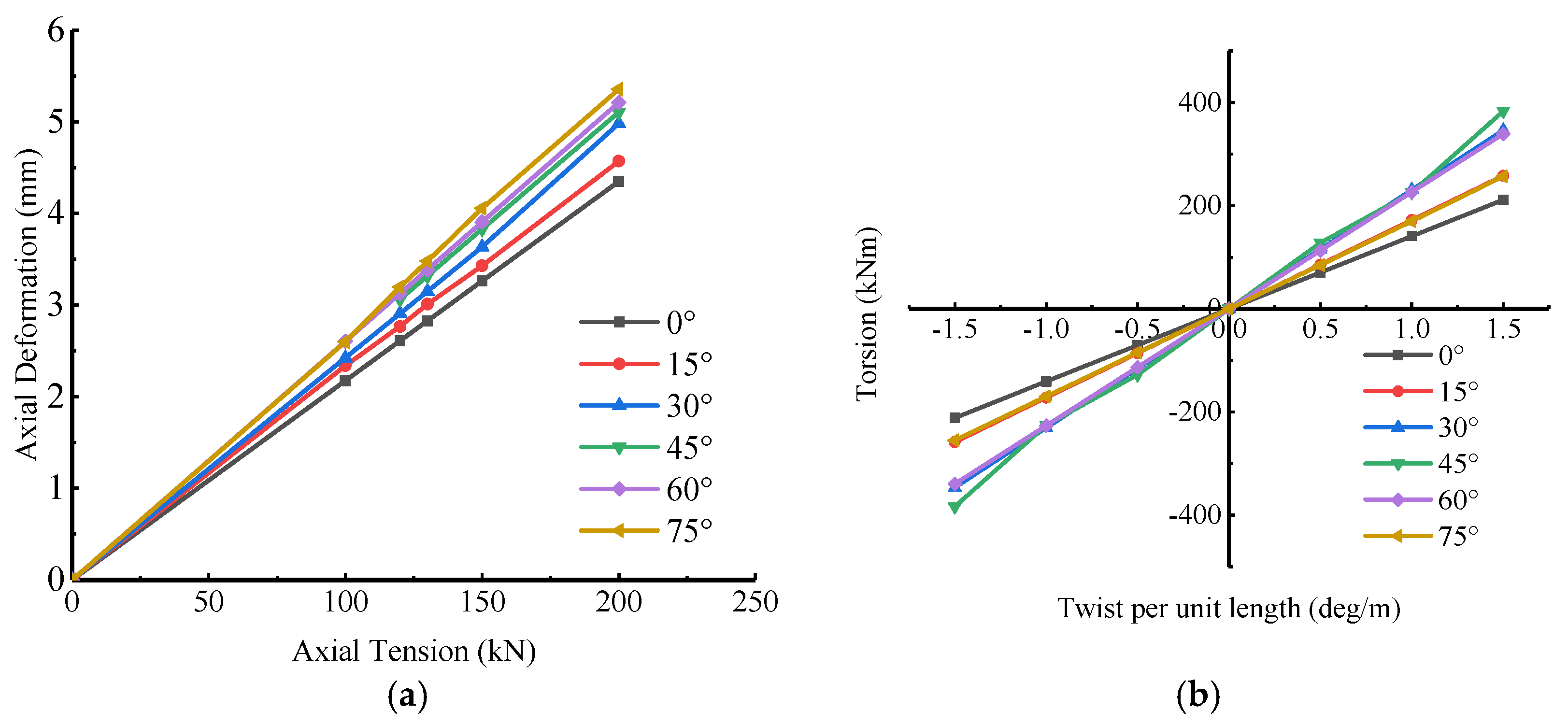
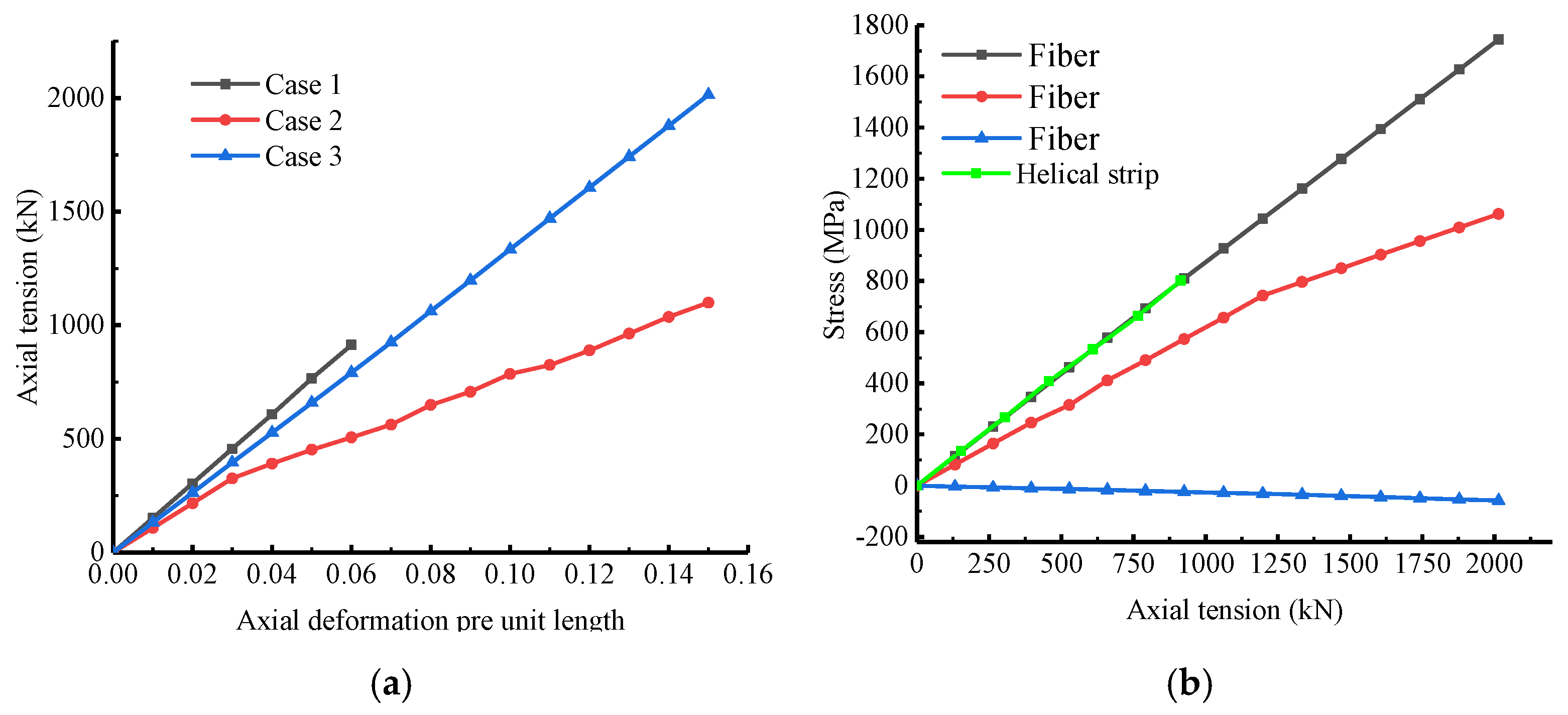
3.2. Pure Axial Tensile
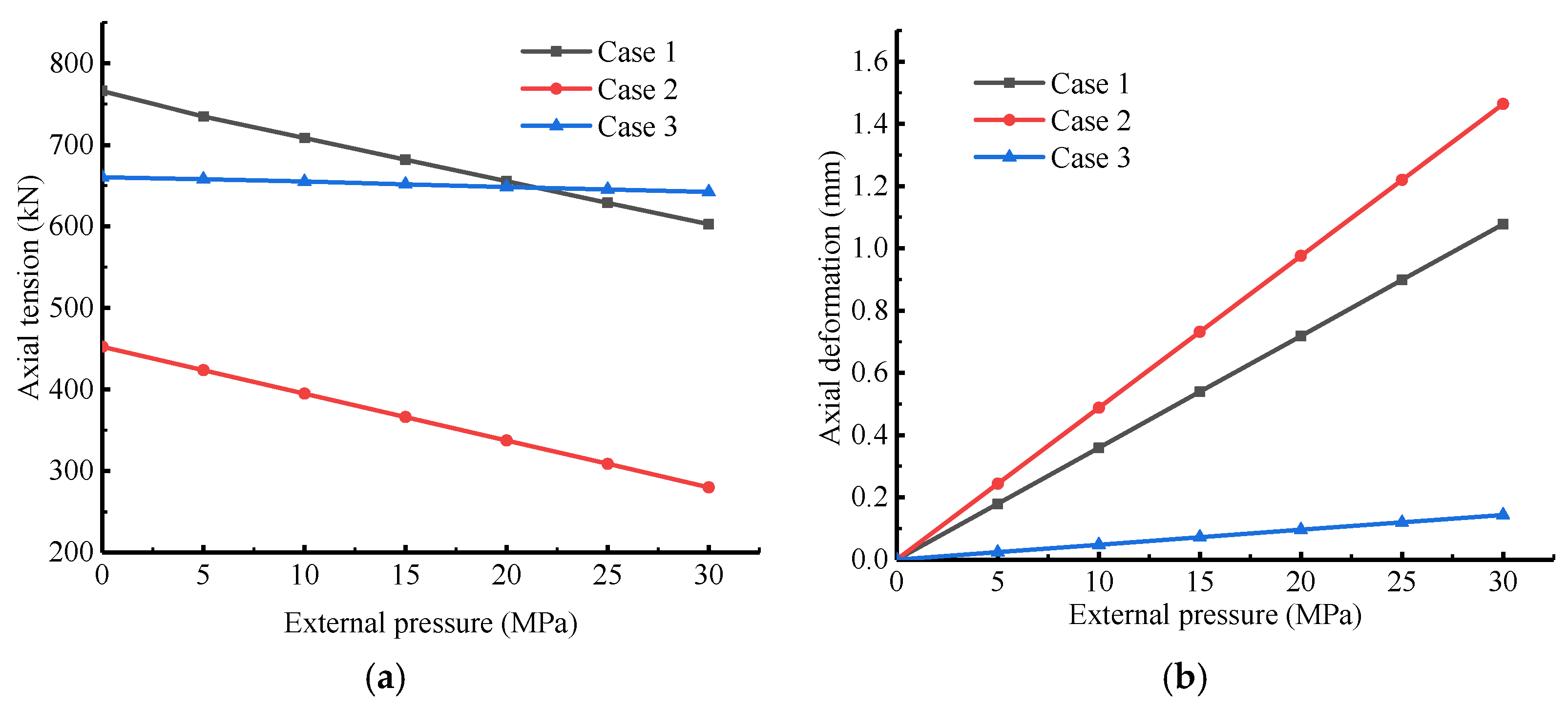
3.3. Tension and External Pressure
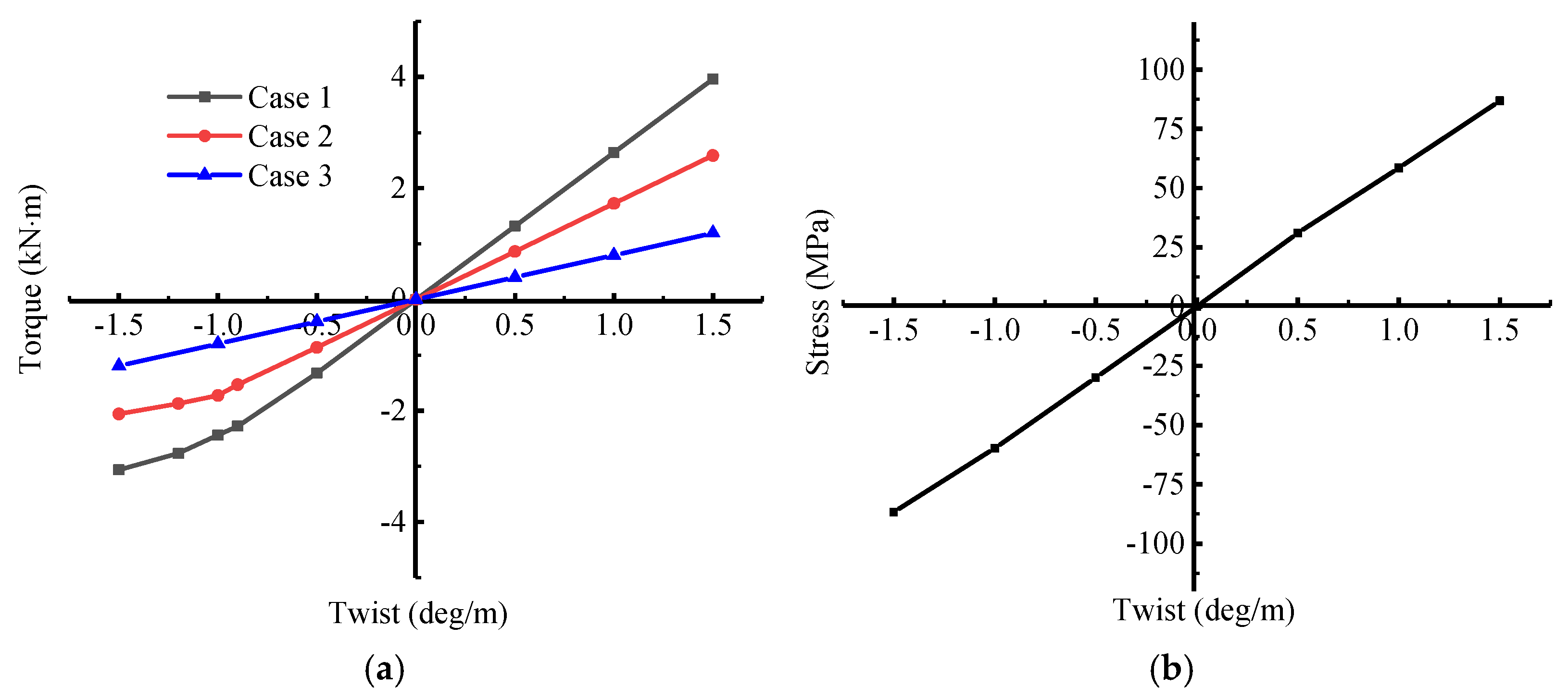
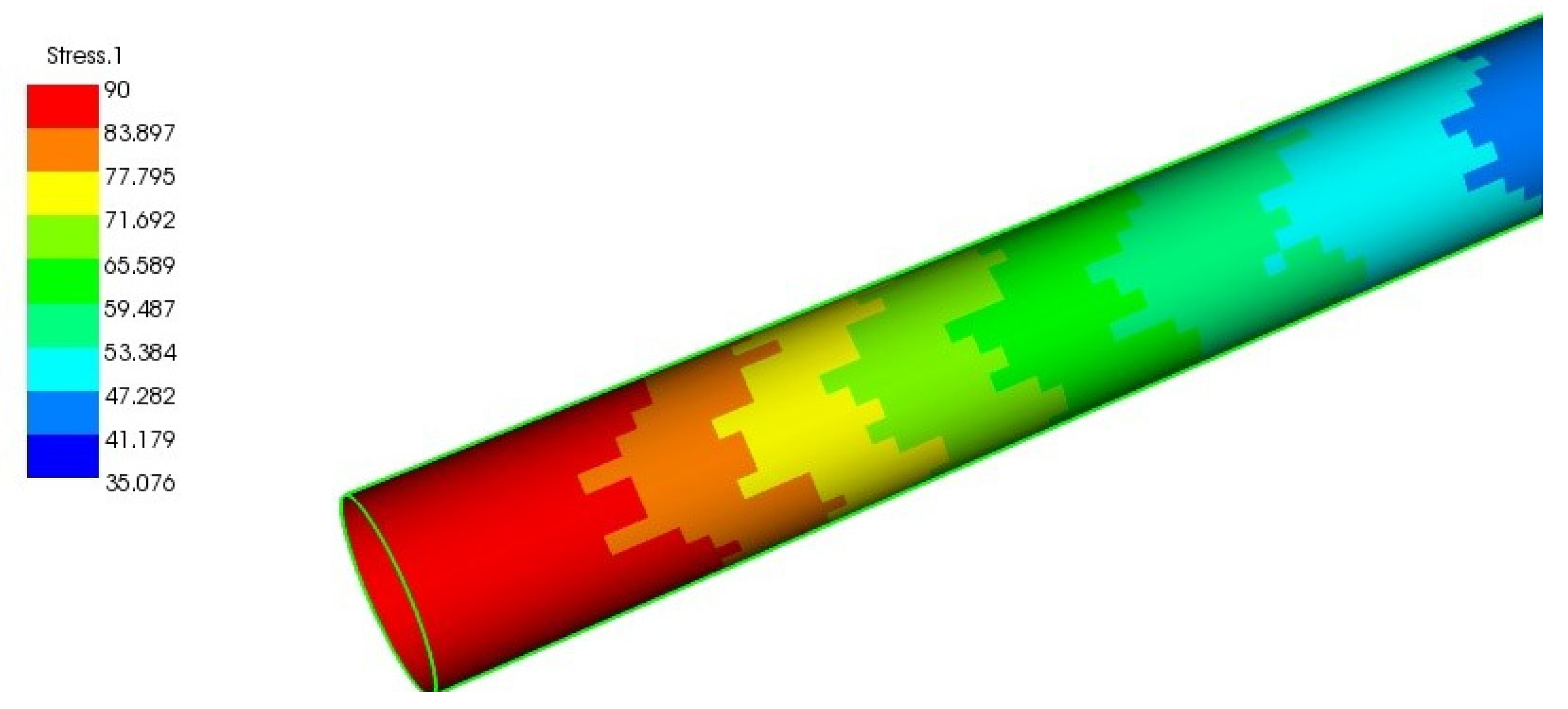
3.4. Torque
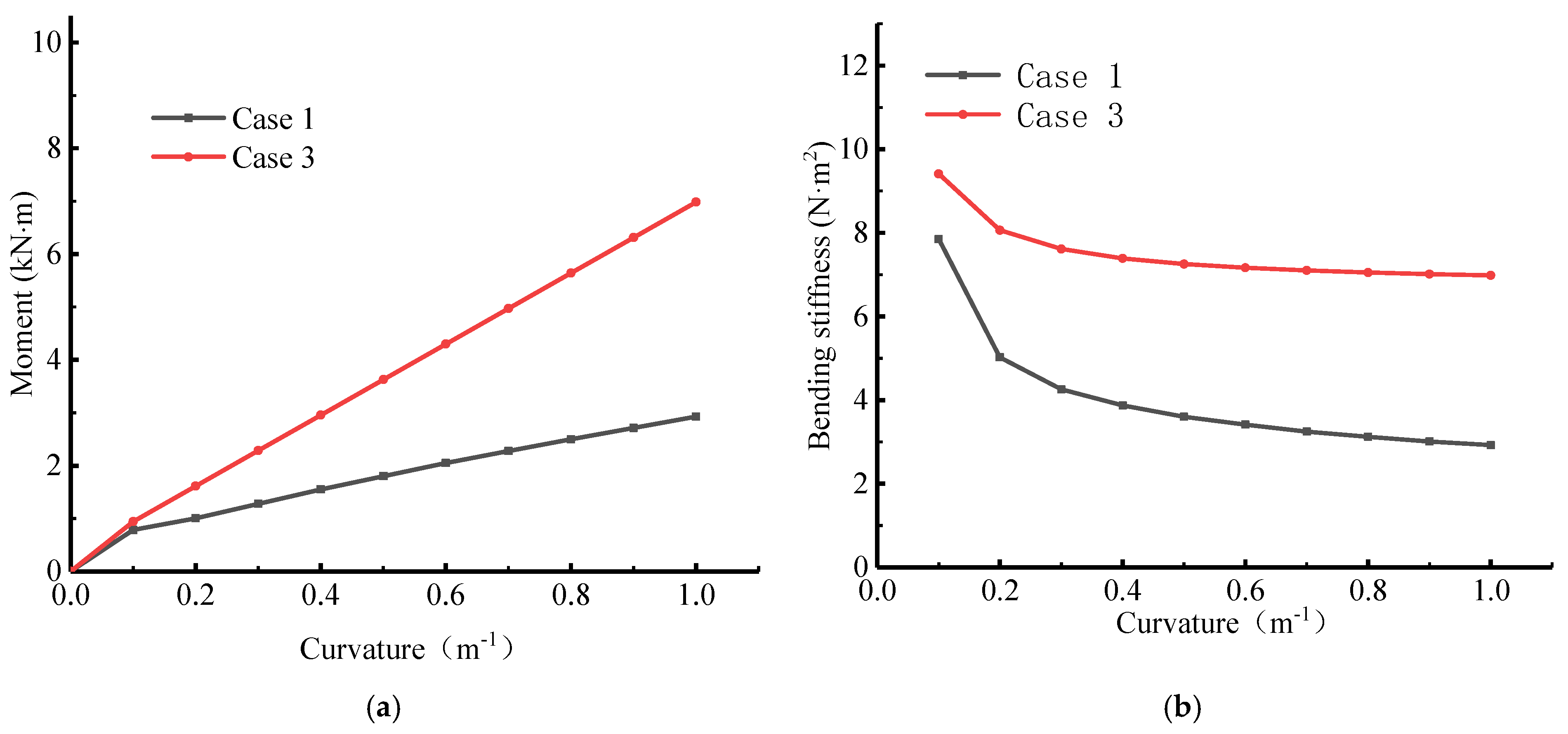
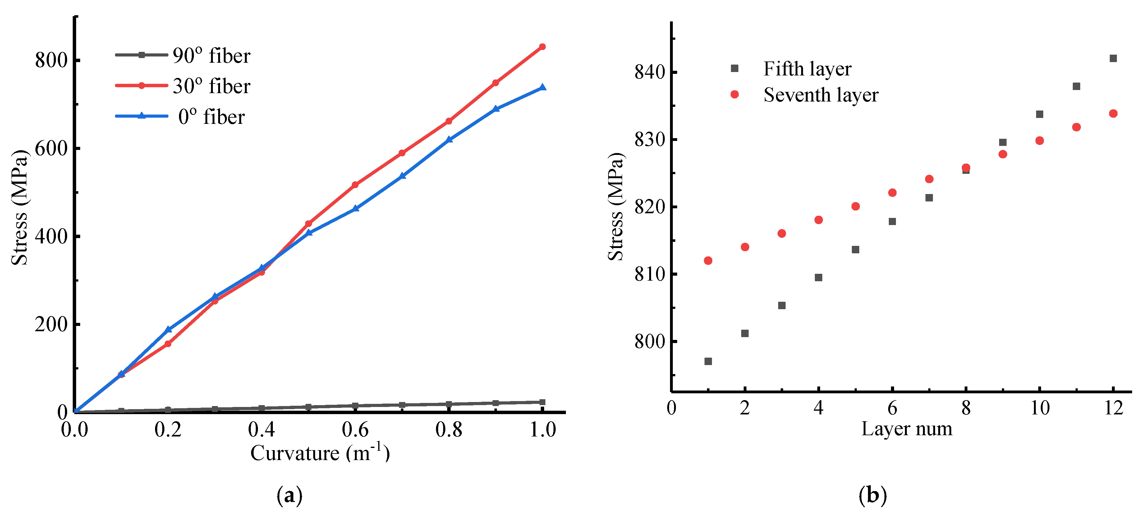
3.5. Bending
4. Conclusions
Author Contributions
Funding
Informed Consent Statement
Data Availability Statement
Acknowledgments
Conflicts of Interest
References
- Dudley, B. BP Energy Outlook; BP Amoco: London, UK, 2018. [Google Scholar]
- Yoo, D.-H.; Jang, B.-S.; Yim, K.-H. Nonlinear finite element analysis of failure modes and ultimate strength of flexible pipes. Mar. Struct. 2017, 54, 50–72. [Google Scholar] [CrossRef]
- API. Recommended Practice for Flexible Pipe, 5th ed.; API RP 17B; American Petroleum Institute: Washington, DC, USA, 2014. [Google Scholar]
- API. Specification for Unbounded Flexible Pipe, APIA Specification 17, 4th ed.; American Petroleum Institute: Washington, DC, USA, 2014. [Google Scholar]
- Ryu, S.; Duggal, A.S.; Heyl, C.N.; Liu, Y. Prediction of deepwater oil offloading buoy response and experimental validation. Int. J. Offshore Polar Eng. 2006, 16, 290–296. [Google Scholar]
- Kang, Y.; Sun, L.; Kang, Z.; Chai, S. Coupled analysis of FPSO and CALM buoy offloading system in West Africa. In Proceedings of the ASME 2014 33rd International Conference on Ocean, Offshore and Arctic Engineering, San Francisco, CA, USA, 8–13 June 2014. [Google Scholar]
- Hovde, G.O.; Kaalstad, J.P.; Skjaastad, O. Offloading in Deep and Ultradeep Water—Main Drivers and Need for Improved Systems. In Proceedings of the Offshore Technology Conference, Houston, TX, USA, 2 May 2005. [Google Scholar]
- Toh, W.; Bin Tan, L.; Jaiman, R.K.; Tay, T.E.; Tan, V. A comprehensive study on composite risers: Material solution, local end fitting design and global response. Mar. Struct. 2018, 61, 155–169. [Google Scholar] [CrossRef]
- Amaechi, C.V.; Gillett, N.; Odijie, A.C.; Hou, X.; Ye, J. Composite risers for deep waters using a numerical modelling approach. Compos. Struct. 2019, 210, 486–499. [Google Scholar] [CrossRef]
- Liu, Q.; Xue, H.; Tang, W.; Yuan, Y. Theoretical and numerical methods to predict the behaviour of unbonded flexible riser with composite armour layers subjected to axial tension. Ocean Eng. 2020, 199, 107038. [Google Scholar] [CrossRef]
- Wang, Z.; Almeida, J.H.S., Jr.; St-Pierre, L.; Wang, Z.; Castro, S.G. Reliability-based buckling optimization with an accelerated Kriging metamodel for filament-wound variable angle tow composite cylinders. Compos. Struct. 2020, 254, 112821. [Google Scholar] [CrossRef]
- Almeida, J.H.S.; Ribeiro, M.L.; Tita, V.; Amico, S.C. Damage and failure in carbon/epoxy filament wound composite tubes under external pressure: Experimental and numerical approaches. Mater. Des. 2016, 96, 431–438. [Google Scholar] [CrossRef]
- Almeida, J.H.S.; Ribeiro, M.L.; Almeida, J.H.S.; Amico, S.C. Stacking sequence optimization in composite tubes under internal pressure based on genetic algorithm accounting for progressive damage. Compos. Struct. 2017, 178, 20–26. [Google Scholar] [CrossRef]
- De Sousa, J.R.; Magluta, C.; Roitman, N.; Vargas-Londono, T.; Campello, G. A Study on the Response of a Flexible Pipe to Combined Axisymmetric Loads. In Proceedings of the ASME 2013 32nd International Conference on Ocean: Offshore and Arctic Engineering, Nantes, France, 9–14 June 2013. [Google Scholar]
- Out, J.; Von Morgen, B. Slippage of helical reinforcing on a bent cylinder. Eng. Struct. 1997, 19, 507–515. [Google Scholar] [CrossRef]
- Zhou, Y.; Vaz, M.A. A quasi-linear method for frictional model in helical layers of bent flexible risers. Mar. Struct. 2017, 51, 152–173. [Google Scholar] [CrossRef]
- Tang, L.; He, W.; Zhu, X.; Zhou, Y. Mechanical analysis of un-bonded flexible pipe tensile armor under combined loads. Int. J. Press. Vessel. Pip. 2019, 171, 217–223. [Google Scholar] [CrossRef]
- Bai, Y.; Lu, Y.; Cheng, P. Analytical prediction of umbilical behavior under combined tension and internal pressure. Ocean Eng. 2015, 109, 135–144. [Google Scholar] [CrossRef]
- Merino, H.E.M.; de Sousa, J.R.M.; Magluta, C.; Roitman, N. Numerical and Experimental Study of a Flexible Pipe under Torsion. In Proceedings of the International Conference on Offshore Mechanics and Arctic Engineering, Shanghai, China, 6–11 June 2010; pp. 911–922. [Google Scholar]
- Bussetta, P.; Marceau, D.; Ponthot, J.-P. The adapted augmented Lagrangian method: A new method for the resolution of the mechanical frictional contact problem. Comput. Mech. 2011, 49, 259–275. [Google Scholar] [CrossRef]
- Gu, J.; Chen, P. Some modifications of Hashin’s failure criteria for unidirectional composite materials. Compos. Struct. 2017, 182, 143–152. [Google Scholar] [CrossRef]
- Tserpes, K.I.; Papanikos, P.; Kermanidis, T. A three-dimensional progressive damage model for bolted joints in composite laminates subjected to tensile loading. Fatigue Fract. Eng. Mater. Struct. 2001, 24, 663–675. [Google Scholar] [CrossRef]
- Zhang, X.; Gou, R.; Yang, W.; Chang, X. Vortex-induced vibration dynamics of a flexible fluid-conveying marine riser subjected to axial harmonic tension. J. Braz. Soc. Mech. Sci. Eng. 2018, 40, 365. [Google Scholar] [CrossRef]
- Liu, P.; Gu, Z.; Yang, Y.; Peng, X. A nonlocal finite element model for progressive failure analysis of composite laminates. Compos. Part B Eng. 2016, 86, 178–196. [Google Scholar] [CrossRef]
- Novitsky, A.; Gray, F. Flexible and Rigid Pipe Solutions in the Development of Ultra-Deepwater Fields. Int. Conf. Offshore Mech. Arct. Eng. 2003, 36827, 755–770. [Google Scholar]
- Vaz, M.; Rizzo, N. A finite element model for flexible pipe armor wire instability. Mar. Struct. 2011, 24, 275–291. [Google Scholar] [CrossRef]
- Li, X.; Jiang, X.; Hopman, H. A strain energy-based equivalent layer method for the prediction of critical collapse pressure of flexible risers. Ocean Eng. 2018, 164, 248–255. [Google Scholar] [CrossRef]
- Ebrahimi, A.; Kenny, S.; Hussein, A. Finite Element Investigation on the Tensile Armor Wire Response of Flexible Pipe for Axisymmetric Loading Conditions Using an Implicit Solver. J. Offshore Mech. Arct. Eng. 2018, 140, 041402. [Google Scholar] [CrossRef]
- De Sousa, J.R.; Magluta, C.; Roitman, N.; Ellwanger, G.B.; Lima, E.C.; Papaleo, A. On the response of flexible risers to loads imposed by hydraulic collars. Appl. Ocean Res. 2009, 31, 157–170. [Google Scholar] [CrossRef]


| Case | Amount of Layer | Tensile Armor | Figure |
|---|---|---|---|
| case 1 | 8 | 2 carbon steel tensile armor | As shown in Figure 2 |
| case 2 | 12 | 4 spiral carbon fiber composite tensile armor | Technip and reference |
| case 3 | 8 | 2 cylindrical carbon fiber composite tensile armor | As shown in Figure 3 |
| No. | Type | Material | Inner Radius (mm) | External Radius (mm) | Angle | Thickness (mm) | Moment of Inertia (mm4) | Width (mm) |
|---|---|---|---|---|---|---|---|---|
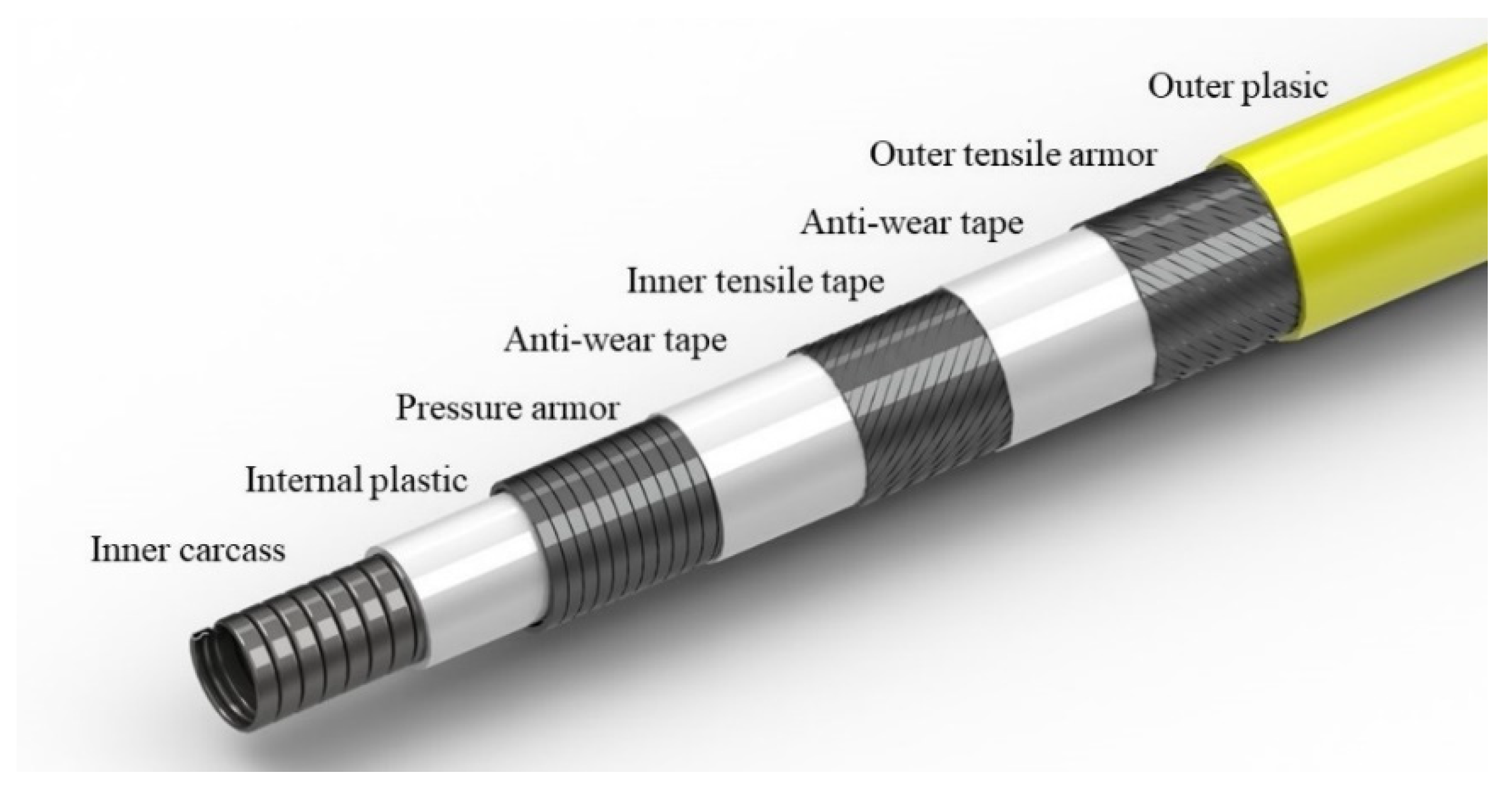
| 1 | Carcass | AISI 304 | 31.75 | 35.25 | +87.6° (1) | 3.5 | 23.1 | 5.6 |
| 2 | Internal plastic | Polyamide 11 | 35.25 | 40.25 | - | 5.0 | - | - |
| 3 | Pressure armor | Carbon steel | 40.25 | 46.85 | 85.6° | 6.6 | 173.4 | 8.73 |
| 4 | Anti-wear tape | Polyamide 11 | 46.85 | 48.85 | - | 2 | - | - |
| 5 | Internal tensile armor | Carbon steel | 48.85 | 51.35 | +30° (32) | 2.5 | 8 | |
| 6 | Anti-wear tape | Polyamide 11 | 51.35 | 52.85 | - | 1.5 | - | - |
| 7 | Outer tensile armor | Carbon steel | 52.85 | 55.35 | −30° (34) | 2.5 | 8 | |
| 8 | Fabric tape | Polyamide | 55.35 | 55.85 | - | 0.5 | - | - |
| 9 | Out plastic | Polyamide | 55.85 | 60.85 | - | 5.0 | - | - |
| Material | E (MPa) | ||
|---|---|---|---|
| AISI 304 | 7930 | 205 × 103 | 0.3 |
| Polyamide 11 | 803 | 345 | 0.3 |
| Carbon steel | 7820 | 205 × 103 | 0.3 |
| Polyamide (eighth) | 803 | 345 | 0.3 |
| Polyamide (ninth) | 803 | 215 | 0.3 |
| Carbon fiber/Epoxy(T700) | Density (kg/m2) | 1580 | (MPa) | 900 |
| E1 (GPa) | 120 | (MPa) | 20 | |
| E2 =E3 (GPa) | 10 | (MPa) | 240 | |
| G12 = G13 (GPa) | 5 | (MPa) | 18 | |
| G23 (GPa) | 5 | = | 0.2 | |
| (MPa) | 1800 | 0.27 |
| Name | Thickness (mm) | Sequence and Orientation |
|---|---|---|
| Internal tensile armor | 2.4 | [902, 2, 06, 06, –2, 902] |
| Outer tensile armor | 2.4 | [902, –2, 06, 06, 2, 902] |
Publisher’s Note: MDPI stays neutral with regard to jurisdictional claims in published maps and institutional affiliations. |
© 2020 by the authors. Licensee MDPI, Basel, Switzerland. This article is an open access article distributed under the terms and conditions of the Creative Commons Attribution (CC BY) license (http://creativecommons.org/licenses/by/4.0/).
Share and Cite
Zhang, H.; Tong, L.; Addo, M.A. Mechanical Analysis of Flexible Riser with Carbon Fiber Composite Tension Armor. J. Compos. Sci. 2021, 5, 3. https://doi.org/10.3390/jcs5010003
Zhang H, Tong L, Addo MA. Mechanical Analysis of Flexible Riser with Carbon Fiber Composite Tension Armor. Journal of Composites Science. 2021; 5(1):3. https://doi.org/10.3390/jcs5010003
Chicago/Turabian StyleZhang, Haichen, Lili Tong, and Michael Anim Addo. 2021. "Mechanical Analysis of Flexible Riser with Carbon Fiber Composite Tension Armor" Journal of Composites Science 5, no. 1: 3. https://doi.org/10.3390/jcs5010003
APA StyleZhang, H., Tong, L., & Addo, M. A. (2021). Mechanical Analysis of Flexible Riser with Carbon Fiber Composite Tension Armor. Journal of Composites Science, 5(1), 3. https://doi.org/10.3390/jcs5010003