Electrical Conductivity and Electromagnetic Shielding Effectiveness of Bio-Composites


Abstract
1. Introduction
2. Materials
3. Experimental
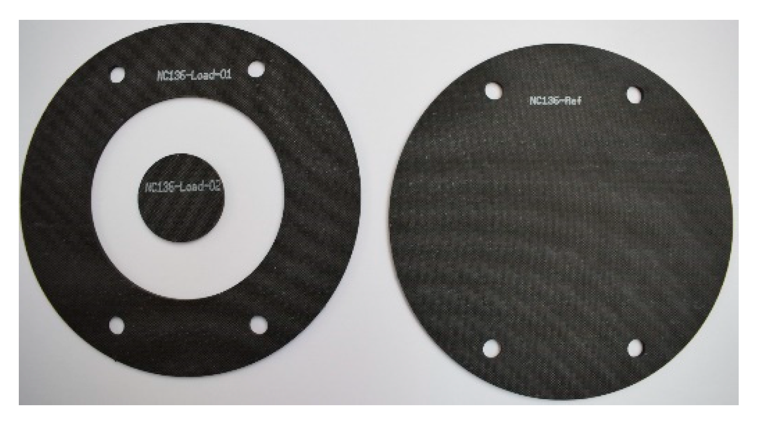
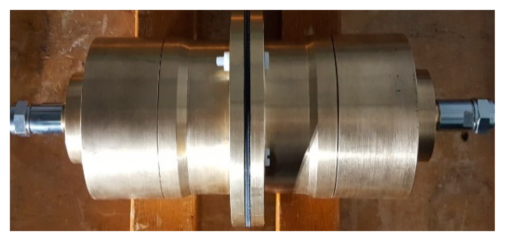
4. EMSE Tests
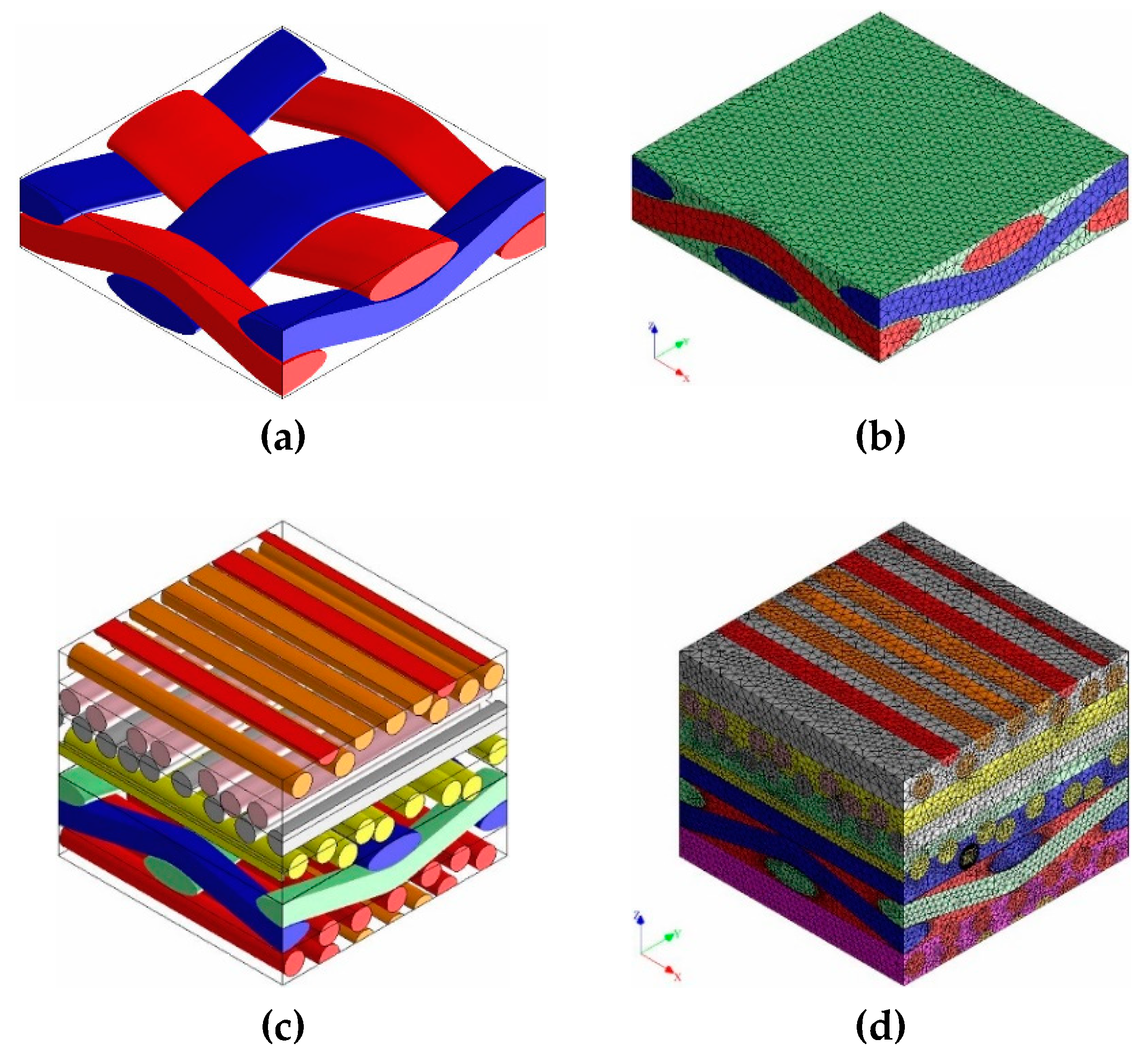
5. Numerical Analysis
6. Experimental Results
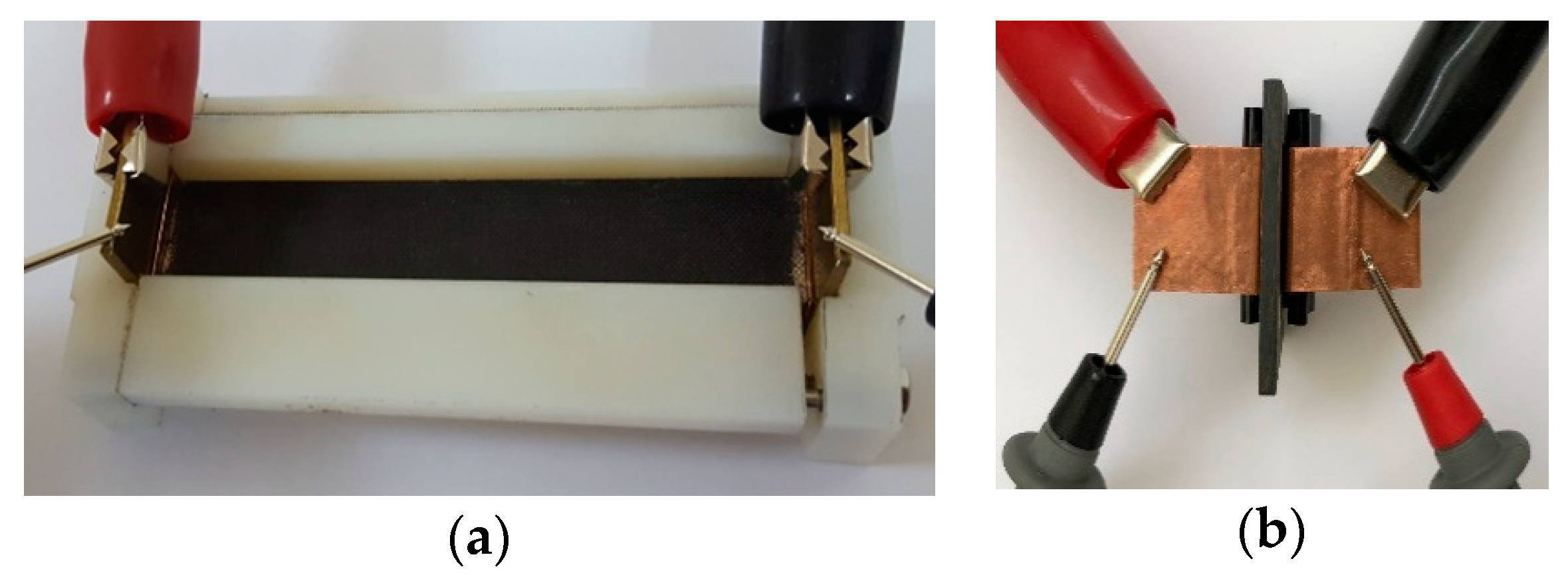
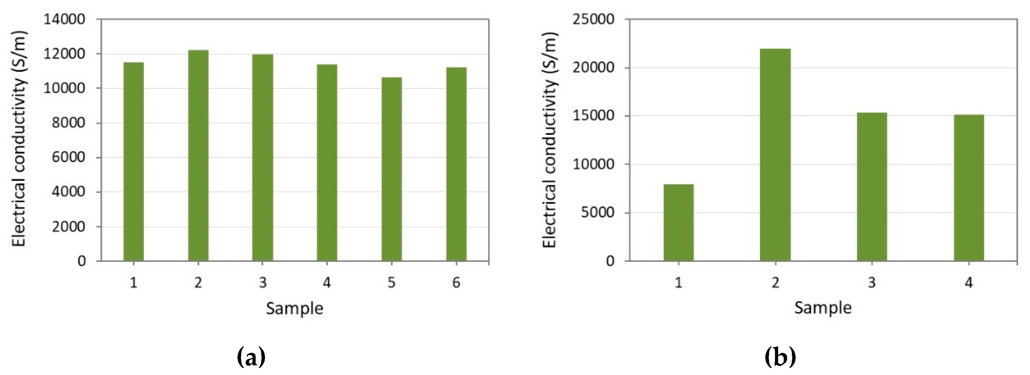
6.1. Electrical Conductivity
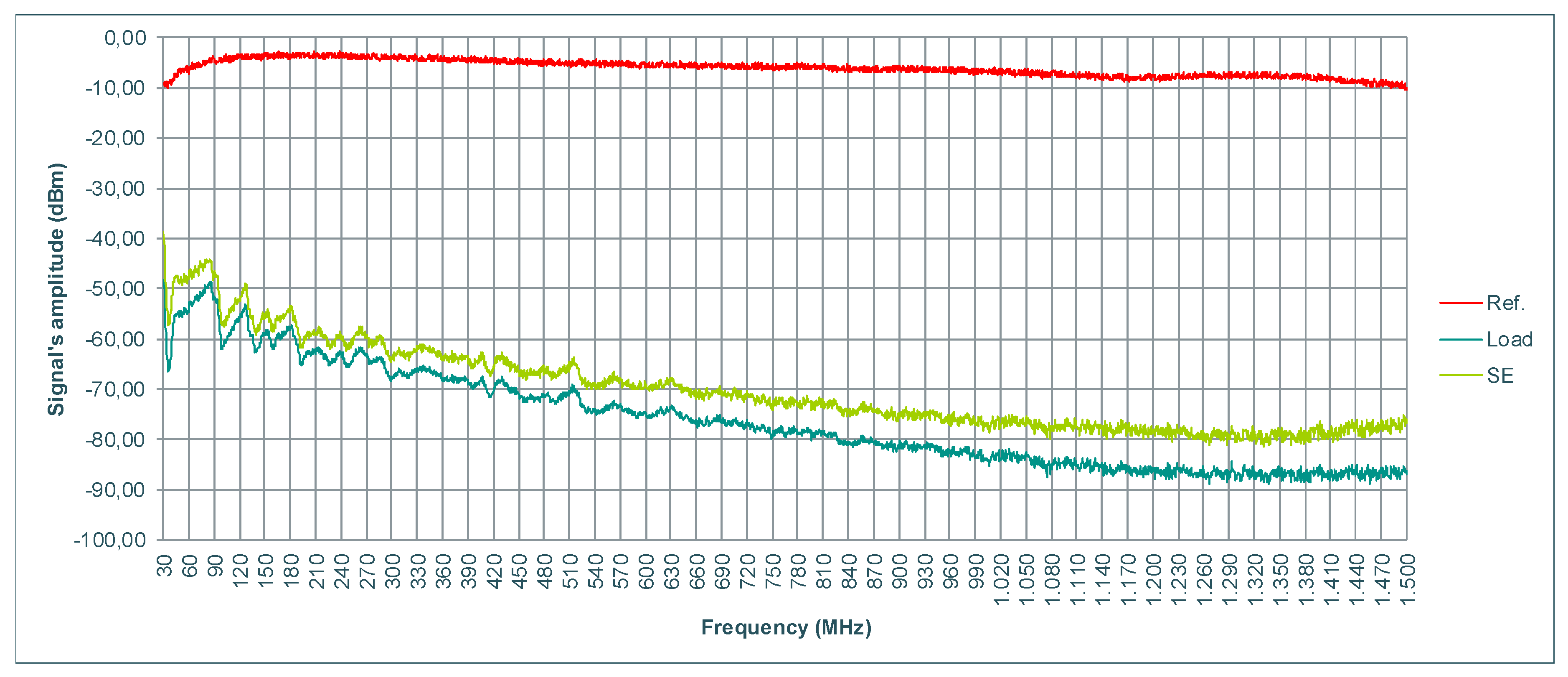
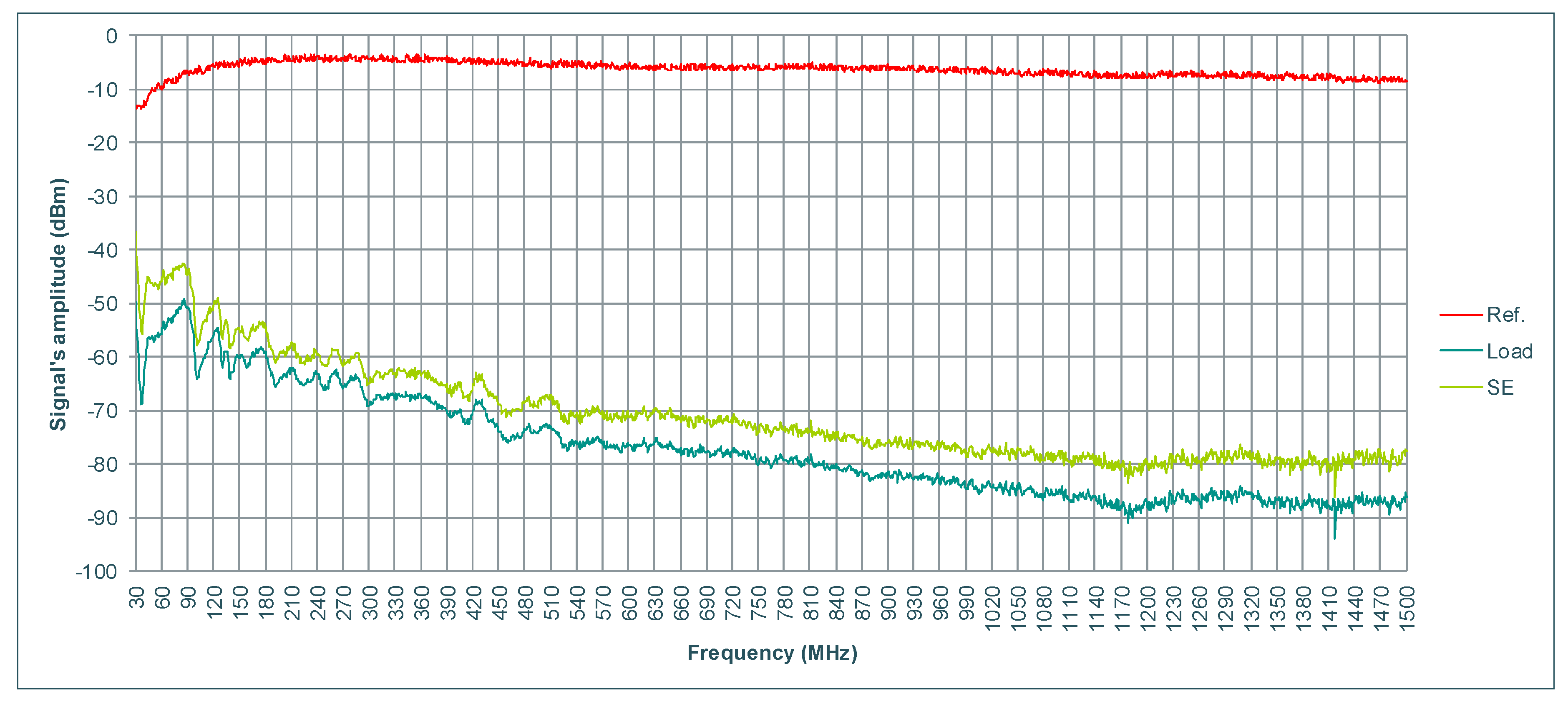
6.2. EMSE
7. Numerical Results
8. Conclusions
Author Contributions
Funding
Conflicts of Interest
References
- Prasad, M.; Kumari, K. Toxicity of Crude Oil to the Survival of the Fresh Water FishPuntius sophore (HAM.). Acta Hydrochimica et Hydrobiologica 1987, 15, 29–36. [Google Scholar] [CrossRef]
- Tzatzadakis, V.; Tserpes, K. Production of a novel bio-based structural adhesive and characterization of mechanical properties. J. Adhes. 2020, 1–16. [Google Scholar] [CrossRef]
- Encyclopedia Britannica. Plastic Pollution|Sources & Effects. 2019. Available online: https://www.britannica.com/science/plastic-pollution (accessed on 26 September 2019).
- Quispe, C.; Coronado, C.; Carvalho, J., Jr. Glycerol: Production, consumption, prices, characterization and new trends in combustion. Renew. Sustain. Energy Rev. 2013, 27, 475–493. [Google Scholar] [CrossRef]
- Tserpes, K.; Tzatzadakis, V.; Katsiropoulos, C. Effect of hygrothermal ageing on the interlaminar shear strength of carbon fiber-reinforced rosin-based epoxy bio-composites. Compos. Struct. 2019, 226, 111211. [Google Scholar] [CrossRef]
- Worldwatch.org. Global Plastic Production Rises, Recycling Lags|Worldwatch Institute. 2019. Available online: http://www.worldwatch.org/global-plastic-production-rises-recyclinglags-0 (accessed on 26 September 2019).
- Bachmann, J.; Yi, X.; Gong, H.; Martinez, X.; Bugeda, G.; Oller, S.; Tserpes, K.; Ramon, E.; Paris, C.; Moreira, P.; et al. Outlook on ecologically improved composites for aviation interior and secondary structures. CEAS Aeronaut. J. 2018, 9, 533–543. [Google Scholar] [CrossRef]
- Yi, X.; Tserpes, K. Special Issue: ECO-COMPASS: Ecological and Multifunctional Composites for Application in Aircraft Interior and Secondary Structures. Aerospace 2019, 6, 17. [Google Scholar] [CrossRef]
- Rakov, V.; Rachidi, F. Overview of Recent Progress in Lightning Research and Lightning Protection. IEEE Trans. Electromagn. Compat. 2009, 51, 428–442. [Google Scholar] [CrossRef]
- White, D.; Mardiguian, M. Electromagnetic Shielding; Emf-emi control, Inc.: Gainesville, VA, USA, 1988. [Google Scholar]
- Von Klemperer, C.J.; Maharaj, D. Composite electromagnetic interference shielding materials for aerospace applications. Compos. Struct. 2009, 91, 467–472. [Google Scholar] [CrossRef]
- Hutter, H.P.; Moshammer, H.; Wallner, P.; Kundi, M. Subjective symptoms, sleeping problems, and cognitive performance in subjects living near mobile phone base stations. Occup. Environ. Med. 2006, 63, 307–313. [Google Scholar] [CrossRef] [PubMed]
- International Workshop on Electromagnetic Field Hypersensitivity (2004: Prague, Czech Republic), Mild, Kjell Hansson, Repacholi, Michael H, Deventer, Emilie van & World Health Organization. (2006). Electromagnetic hypersensitivity: proceedings, International Workshop on Electromagnetic Field Hypersensitivity, Prague, Czech Republic, 25–27, 2004/editors, Kjell Hansson Mild, Mike Repacholi, Emilie van Deventer. World Health Organization. Available online: https://apps.who.int/iris/handle/10665/43435 (accessed on 18 March 2020).
- Singh, S.; Kapoor, N. Health Implications of Electromagnetic Fields, Mechanisms of Action, and Research Needs. Adv. Biol. 2014, 2014, 198609. [Google Scholar] [CrossRef]
- Genuis, S.J.; Lipp, C.T. Electromagnetic hypersensitivity: Fact or fiction? Sci. Total Environ. 2012, 414, 103–112. [Google Scholar] [CrossRef] [PubMed]
- Kaprana, A.; Karatzanis, A.; Prokopakis, E.; Panagiotaki, I.; Vardiambasis, I.; Adamidis, G.; Christodoulou, P.; Velegrakis, G. Studying the effects of mobile phone use on the auditory system and the central nervous system: A review of the literature and future directions. Eur. Arch. Oto Rhino Laryngol. 2008, 265, 1011–1019. [Google Scholar] [CrossRef]
- Hamada, A.J.; Singh, A.; Agarwal, A. Cell phones and their impact on male fertility: Fact or fiction. Open Reprod. Sci. J. 2011, 5, 125–137. [Google Scholar]
- Regel, S.J.; Achermann, P. Cognitive performancemeasures in bioelectromagnetic research critical evaluation and recommendations. Environ. Health 2011, 10, 10. [Google Scholar] [CrossRef]
- Leszczynski, D.; Joenväärä, S.; Reivinen, J.; Kuokka, R. Nonthermal activation of the hsp27/p38MAPK stress pathway by mobile phone radiation in human endothelial cells: Molecular mechanism for cancer- and blood-brain barrier-related effects. Differentiation 2002, 70, 120–129. [Google Scholar] [CrossRef]
- López-Martín, E.; Relova-Quinteiro, J.L.; Gallego-Gómez, R.; Peleteiro-Fernández, M.; Jorge–Barreiro, F.J.; Ares-Pena, F.J. GSM radiation triggers seizures and increases cerebral c-Fos positivity in rats pretreated with subconvulsive doses of picrotoxin. Neurosci. Lett. 2006, 398, 139–144. [Google Scholar] [CrossRef]
- Rifai, A.; Hakami, M. Health Hazards of Electromagnetic Radiation. J. Biosci. Med. 2014, 2, 1–12. [Google Scholar] [CrossRef][Green Version]
- Adebayo, E.; Adeeyo, A.; Ogundiran, M.; Olabisi, O. Bio-physical effects of radiofrequency electromagnetic radiation (RF-EMR) on blood parameters, spermatozoa, liver, kidney and heart of albino rats. J. King Saud Univ. Sci. 2019, 31, 813–821. [Google Scholar] [CrossRef]
- Adebayo, E.; Adeeyo, A.; Ayandele, A.; Omomowo, I. Effect of Radiofrequency Radiation from Telecommunication Base Stations on Microbial Diversity and Antibiotic Resistance. J. Appl. Sci. Environ. Manag. 2015, 18, 669. [Google Scholar] [CrossRef]
- Goodman, R.; Chizmadzhev, Y.; Shirley-Henderson, A. Electromagnetic fields and cells. J. Cell. Biochem. 1993, 51, 436–441. [Google Scholar] [CrossRef] [PubMed]
- Airbus, S.A.S. AITM 2-0064. Airbus Test Method. In Electrical Resistance for a Composite Laminate with Carbon Fibre: Measurement along X or Y Direction; Engineering Directorate: Blagnac, France, 2010. [Google Scholar]
- Airbus, S.A.S. AITM 2-0065. Airbus Test Method. In Electrical Resistance for a Composite Laminate with Carbon Fibre: Measurement along Z Direction; Engineering Directorate: Blagnac, France, 2010. [Google Scholar]
- ASTM Standard D4935, 2010. In Standard Test Method for Measuring the Electromagnetic Shielding Effectiveness of Planar Materials; ASTM International: West Conshohocken, PA, USA, 2010.
- DIGIMAT User’s Manual. In Release 2017.1-April 2017; eXstream Engineering: Brussels, Belgium, 2017.
- Piche, A.; Revel, I.; Peres, G. Experimental and Numerical Methods to Characterize Electrical Behaviour of Carbon Fiber Composites Used in Aeronautic Industry. Advances in Composite Materials - Analysis of Natural and Man-Made Materials. 2011; Available online: https://www.intechopen.com/books/advances-in-composite-materials-analysis-of-natural-and-man-made-materials/experimental-and-numerical-methods-to-characterize-electrical-behaviour-of-carbon-fiber-composites-u (accessed on 18 March 2020).
- Gao, S.P.; Lee, H.M.; Gao, R.X.K.; Lim, Q.F.; Thitsartarn, W.; Liu, E.X.; Png, C.E. Effective Modeling of Multidirectional CFRP Panels Based on Characterizing Unidirectional Samples for Studying the Lightning Direct Effect. 2017. Available online: https://ieeexplore.ieee.org/document/8105177 (accessed on 17 March 2020).
- Munalli, D.; Chronopoulos, D.; Greedy, S. Electromagnetic shielding effectiveness of fiber-reinforced composites: A preliminary study. In Proceedings of the 9th European Workshop on Structural Health Monitoring, Manchester, UK, 10–13 July 2018. [Google Scholar]
- Tserpes, K.; Tzatzadakis, V.; Bachmann, J. Electrical Conductivity and Electromagnetic Shielding Effectiveness of Bio-Composites. In Proceedings of the European Conference on Multifunctional Structures (EMUS), International Centre for Numerical Methods in Engineering (CIMNE), Barcelona, Spain, 11–12 June 2019; pp. 81–89, ISBN 978-84-949194-4-2. [Google Scholar]


| Property | Carbon | Flax |
|---|---|---|
| Density (g/cm3) | 1.8 | 1.54 |
| Electrical conductivity (S/m) | 70,000 | 100 |
| Dimensions of yarn (mm) | 0.15 × 0.5 | 0.15 × 0.4 |
© 2020 by the authors. Licensee MDPI, Basel, Switzerland. This article is an open access article distributed under the terms and conditions of the Creative Commons Attribution (CC BY) license (http://creativecommons.org/licenses/by/4.0/).
Share and Cite
Tserpes, K.; Tzatzadakis, V.; Bachmann, J. Electrical Conductivity and Electromagnetic Shielding Effectiveness of Bio-Composites. J. Compos. Sci. 2020, 4, 28. https://doi.org/10.3390/jcs4010028
Tserpes K, Tzatzadakis V, Bachmann J. Electrical Conductivity and Electromagnetic Shielding Effectiveness of Bio-Composites. Journal of Composites Science. 2020; 4(1):28. https://doi.org/10.3390/jcs4010028
Chicago/Turabian StyleTserpes, Konstantinos, Vasileios Tzatzadakis, and Jens Bachmann. 2020. "Electrical Conductivity and Electromagnetic Shielding Effectiveness of Bio-Composites" Journal of Composites Science 4, no. 1: 28. https://doi.org/10.3390/jcs4010028
APA StyleTserpes, K., Tzatzadakis, V., & Bachmann, J. (2020). Electrical Conductivity and Electromagnetic Shielding Effectiveness of Bio-Composites. Journal of Composites Science, 4(1), 28. https://doi.org/10.3390/jcs4010028