Article

Effect of Resin Rich Veil Cloth Layers on the Uniaxial Tensile Behavior of Carbon Fiber Reinforced Fiber Metal Laminates

Department of Mechanical Engineering, Wayne State University, Detroit, MI 48202, USA
*
Authors to whom correspondence should be addressed.
J. Compos. Sci. 2018, 2(4), 61; https://doi.org/10.3390/jcs2040061
Submission received: 9 August 2018 / Revised: 28 September 2018 / Accepted: 15 October 2018 / Published: 19 October 2018

Abstract

:
The influence of stacking sequence and resin rich (polyester veil cloth) layers, which were used to improve the adhesion between carbon fiber/epoxy (CFRP) and aluminum layers (AL), on the uniaxial tensile response of carbon fiber reinforced aluminum laminates (CARALL) was investigated in this research study. The metal volume fraction was varied to prepare two types of CARALL laminates having a 3/2 configuration with the help of a vacuum press without using any adhesive film. Numerical simulations were performed by utilizing commercially available finite element (FE) code, LS-Dyna to predict the tensile response of these laminates with initialization of predicted thermal residual stresses that developed during curing of laminates. Delamination failure was considered in the numerical simulation by utilizing the well-known B-K mixed-mode damage propagation model. It was found that addition of epoxy resin rich (polyester veil cloth) layers used for enhancement of interfacial bond adhesion and to ensure no separation between AL-CFRP layers increased the tensile strength of CARALL laminates.

1. Introduction

Fiber metal laminates (FMLs) are a good substitute for metallic structures in the automotive industry due to their better tensile properties [1,2], fatigue and fracture resistance [2,3,4], and superior damage threshold energy [5,6] than conventional metallic alloys. The FMLs have complex failure mechanisms due to the inhomogeneous nature of their constituents, with significantly diverse properties [7]. Plastic deformation of aluminum layers, matrix cracking, fiber fracture, and delamination between adjacent plies are common failure mechanisms that may contribute to damage of FML [8,9]. Glass fiber reinforced aluminum laminates (GLARE) is an important member of the FML family, which have found many aerospace structural applications. The effect of factors, such as delamination [10,11,12,13], the stacking sequence of composite layers [14,15,16], and the number of notches [17] and their sizes [10,18,19], on the strength of FMLs is studied in literature. Although GLARE offers excellent specific properties over traditional aluminum alloys, it does not find the application in higher loadbearing structures [20] due to the lower tensile strength as compared to carbon fiber reinforced aluminum laminates (CARALL) FML. CARALL laminates approximately show 10% higher tensile strength than GLARE [21] for the same fiber volume fraction. FMLs with carbon fiber, commonly known as CARALL, offers better crashworthiness [22,23], higher energy absorption, high specific modulus, better yield strength, and excellent fatigue resistance as compared to glass or aramid fiber reinforced aluminum laminates [24,25]. Thus, carbon fiber reinforced FMLs can be very attractive for the automotive industry to develop lightweight automobiles. Many researchers, through tensile, impact, and flexural experiments, studied the mechanical behavior of CARALL FMLs. Dov et al. [26] studied the mechanical behavior of a laminate consisting of monolithic thin alumina plates alternating with unidirectional carbon/epoxy prepreg tapes. Multiple fracture mechanisms led the FML to exhibit pseudo-ductile behavior and enhanced strain energy dissipation. A minimal volume fraction of the reinforcing layers is required to exhibit this behavior. They also investigated the influence of a number of layers and volume fraction on transverse properties.
Lin et al. [27] investigated the thermal residual strains in various carbon fiber reinforced aluminum laminates (CARALL) by both experimental methods and theoretical analysis. They used the deflection of an asymmetric laminate and the yield point shift of the aluminum alloy in the CARALL laminate as experimental methods to measure thermal strains. Classical lamination theory was used to perform the theoretical calculation of residual strains. A good agreement was observed in residual strains determined by each experimental method and by theoretical calculation. The thermal residual stress in the aluminum layer was found to be roughly proportional to the volume fraction of the carbon/epoxy layer for CARALL laminate reinforced with unidirectional carbon fibers.
Lawcock et al. [28] studied the effect of adhesion between aluminum sheets and fiber/epoxy layers on the mechanical properties of carbon-fiber-reinforced metal laminates by using two different ways of aluminum surface treatments methods. They used standard P2-Etch and modified Forest Products Laboratory (FPL) Etch procedures as surface treatment methods with the application of a silane coupling agent. A double cantilever beam experiment conducted by the author showed six times increase in interfacial fracture toughness by using the later surface treatment method. A 10% reduction in interlaminar shear strength was observed for a laminate with poor interfacial adhesion (P2-Etch method) in flexural tests. They found no clear difference in the tensile properties of laminates associated with both surface treatment methods.
The effect of adhesion between the fiber and matrix on the residual strength behavior of carbon-fiber-reinforced metal laminates was studied by using treated and untreated carbon fibers in an epoxy resin system by Lawcock et al. [29]. Interfacial failure was observed in the untreated fiber composites while matrix failure was shown by the treated fiber composites. A reduction of 7.5% was observed in the interlaminar shear strength value for the untreated fiber laminates by both three-point and five point bend tests. An excellent increase in strength for the untreated fiber specimens over the treated ones was found in residual strength and blunt notch tests.
Hu et al. [30] studied the flexural and interlaminar shear strength (ILSS) of carbon fiber reinforced titanium laminates. He found that micro-roughness structures were formed on the titanium surface after anodization, which improved the interlaminar bond strength between titanium and polyimide. He also reported that these FMLs possess excellent flexural and interlaminar properties at both room temperature and elevated temperature and found no delamination between the titanium layer and the fiber-reinforced polyimide layer after 1000 times thermal shock through thermostability tests. Botelho et al. [31] evaluated and compared the adhesion of different families of fiber-epoxy composite/metal laminates using carbon fiber and glass fiber fabrics as reinforcements for the hybrid laminates. They reported that chromic acid anodization (CAA) resulted in better wetting properties. They found out that, for both carbon fiber-epoxy/metal and glass fiber-epoxy metal laminates, the interlaminar shear strength results were close to the interlaminar shear strength results found in the literature (approx. 40.0 MPa).
Zhao et al. [32] used an ultrasonic C-scan and A-scan approach to evaluate the damage of the asymmetric CFRP-Al (carbon fiber reinforced aluminum alloy) laminates. They reported, based on comparison results and pulse echo analysis that when the specimen is subjected to repeat tensile tests with 70% elastic limit strain load of the CFRP laminates, the interface separation between CFRP and Al will not occur, but the delamination within CFRP laminates becomes the major damage of the asymmetric CFRP-Al laminates. Botelho et al. [33] studied the influence of moisture on the shear properties of carbon fiber/epoxy composites and CARALL by using interlaminar shear (ILSS) and Iosipescu tests. They observed that hygrothermal conditioning degraded the Iosipescu shear strength of CF/E and CARALL composites due to the higher moisture absorption in these materials. They have reported a decrease in the shear results by nearly 12%.
Rajkumar et al. [20] studied the effect of strain rate and layup configuration on the tensile and flexural behavior of GLARE and CARALL FMLs having a 3/2 stacking sequence. They observed that tensile strength increased with increasing the strain rate while flexural strength decreased with increasing the strain rate. They also reported that carbon fiber based FMLs have maximum tensile and flexural strength whereas glass fiber based FMLs showed minimum strengths and hybrid structure strengths lies between them. Kim et al. [24] studied the tensile behaviors of CARALL FMLs with different stacking sequences for carbon fiber/epoxy layers at strain rates between 0.001/s and 100/s, and compared the properties of these FMLs to the results of aluminum and carbon fiber reinforced polymer composites tested under the same conditions. They reported that the tensile strength of the AL alloy specimen was decreased by 5% as the strain rate increased. However the tensile strength and the failure strain increased as the strain rate increased for the CARALL FMLs, and the increase in tensile strength varied depending on the stacking sequence of the CFRP layer. Simulating the damage behavior of FMLs with greater accuracy is a challenge due to their complex mechanical response. Currently, finite element (FE) methods are employed to investigate the mechanical response and damage progression in various failure modes of FMLs. To consider the influence of various damage mechanisms on the performance of FMLs, it is necessary to consider progressive damage models in FE analyses. The material constitutive models based on continuum damage mechanics (CDM), assuming both degradation and linear elastic behavior of the composite layers in FMLs, have been employed by a few to study progressive damage simulations of FMLs [34,35,36]. Lapczyk [34] developed a two dimensional (2D) progressive damage model adopting the continuum damage mechanics (CDM)-based linear material degradation factors to study the response of FRP laminates. A 3D model having CDM-based exponential damage factors was proposed by Linde [37], which uses the square index as the key independent variable. The author satisfactorily predicted the failure process and strength of the FML with this model. In the previous CARALL FMLs research studies, the damage behavior of these FMLs with initialization of residual stresses under tensile loading is not studied and numerical modeling to predict the behavior, including damage progression, has not been achieved to date. In this study, we have conducted FE modeling to account for the progressive damage failure of CARALL laminates. Unidirectional carbon fiber-epoxy layers having different stacking sequences are utilized mostly in previous CARALL FML research studies, but plain weave woven carbon fiber-epoxy layers are employed in this work to manufacture CARALL FML samples. In addition, the effect of the layup sequence on the properties of carbon fiber reinforced aluminum laminates is investigated under a static tensile loading condition. The correlations between numerical simulations and experimental results are discussed. It was found that addition of epoxy resin rich (polyester veil cloth) layers used for the enhancement of interfacial bond adhesion and to ensure no separation between the AL-CFRP layers increased the tensile strength of CARALL laminates

2. Materials and Methods

Aluminum 5052-H32 material was used for the aluminum layers in the fiber metal laminate configurations. As 5052-H32 aluminum has excellent finishing qualities, it is often referred to as “Anodize Quality Aluminum”. To cause substantial lowering of the melting point without producing brittleness, magnesium is the major alloying element in 5052. The 5052 series is far stronger than the 1100 or 3000 series aluminum and have good forming qualities. Weldability is also very good for the aluminum 5052 series. The thickness of the 5052-H32 aluminum sheet was 0.5 mm. The chemical composition of aluminum 5052-H32 is given in Table 1 and the mechanical properties of the 5052-H32 aluminum alloy are given in Table 2.
Woven carbon fiber/epoxy prepreg, known as VTM264/CF302, manufactured by CYCTEC was used as a material for the fibrous layers in the fiber metal laminate construction. This prepreg system has a 2 × 2 twill weave fabric style with 3 K FT300B40B fibers. The twill weave fabric style is constructed with interlocking of reinforcement carbon tows upon themselves with over/under placement during the weaving process. Here, the size of the carbon tow is represented by 3 K. A bundle of continuous carbon fibers, with a size, generally, of 5–10 microns, is known as a carbon tow. A number of filaments in tow describes the size of the tow [39]. Multiplication by 1000 is indicated by the letter, K, to the filament number. Therefore, 3000 carbon filaments are contained by a 3 K size carbon tow. 2 × 2 designation stands for that there are two tows per inch in each direction.
Twill weave offers greater conformability and delivers slightly more strength as compared to plain weave counterparts. It is highly desirable for modern composites parts in auto, marine, and sporting goods industries because of its signature appearance. The schematic diagram of fibers with a twill weave construction style is described in Figure 1. The in-plane mechanical properties of the woven carbon fiber/epoxy prepreg are given in Table 3. A viewgraph of woven carbon fiber/epoxy prepreg before curing used in the FML manufacturing is shown in Figure 2a.
The synthetic surface veil used in this research is a non-woven fabric manufactured from Dacron® 106 homopolymer and it is commercially known as Nexus®. This polyester fiber has an aperture design that provides the necessary flexibility for the fabrication. Nexus® polyester fiber surfacing fabrics are formed by a unique binder-free process of hydraulic fiber entanglement that results in a web with both vertical and horizontal fiber orientation. This ability to orient fiber vertically as well as horizontally improves the interlaminar bond strength of surface layers reinforced with Nexus. These fabrics can be applied to both interior and exterior surfaces of products, offering excellent impact, corrosion, weather, and ultravoilet (UV)-resistance. The thickness of polyester surfacing veil cloth is approximately close to 8 mils. A viewgraph of the polyester surfacing veil is shown in Figure 2b.
Fiber metal laminate specimens were cured by using flat steel mold plates of 304.8 mm × 304.8 mm. Release agent was applied to mold plates to facilitate the removal of specimens after curing. Grit paper was used to make the surface of the aluminum sheet slightly rough to increase the interlocking between the carbon fiber and aluminum layers. A schematic of the mechanical interlocking produced by abrasion in the cured laminate is shown in Figure 3a. Aluminum sheets were not treated with any other surface pretreatment, like phosphoric acid etching or chromic acid anodization etc., to make the laminate curing process fast, as is desired in the automotive sector. The aluminum sheets were then cleaned with a solution of acetone to ensure that no grease or any other dirt remained on it. Later, these sheets were cut into the desired profile with the help of a water jet cutting machine. Carbon fiber/epoxy prepreg layers were then cut accordingly with a hand cutter. Prepreg plies were hand laid on the shaped aluminum sheets and no external adhesive was used at the carbon fiber/epoxy and aluminum interface.
The uncured specimens were then placed between the mold plates, which were prepared earlier by applying a mold release agent. The whole system, including mold plates and uncured specimens, was placed in the vacuum press shown in Figure 3b to cure the fiber metal laminate specimens. During the curing process, the layered prepreg and aluminum system was kept in vacuum and 0.35 MPa of pressure was applied on the layered system at 135 °C for 60 min. The carbon fiber/epoxy and aluminum layered system was then cooled by passing mist and water over the platten for 15 min each. The completely cured laminate was removed from the mold plate after the completion of the curing cycle. Cured FML specimens were cleaned with the help of a Dremel tool to remove the extra resin that came outside the samples. Carbon fiber reinforced aluminum laminates with two different stacking sequences were studied in this research. The effect of inserting epoxy resin dipped veil cloth between the aluminum and carbon fiber/epoxy layers was studied on both types of laminates. The layup sequence of all the samples studied in this research work along with the nomenclature adopted for naming the samples is schematically described in Figure 4a,b.
The samples of both configurations were accurately weighed and their geometrical dimensions were measured using a slide caliper before undergoing the test procedure. The calculation of weight savings was done by comparing the calculated weight of samples through a metal volume fraction formulation to the weight of monolithic pure Aluminum 5052-H32 samples. The carbon fiber reinforced laminate specimens with different constituents and layup sequences offer different weight savings results. As expected the addition of resin dipped veil cloth affected the weight saving results by decreasing it by approximately 8–9% due to an increase in the thickness of the laminate. Although there is a decrease in weight savings, there is a possibility of savings approximately around 25% of using CARALL laminates. The total laminate thickness, specimen type, and metal volume fraction of all types of samples is provided in Table 4.

3. Experimental Aspects

Tensile tests were conducted on CARALL fiber metal laminate samples according to the ASTM D 3039 standard to obtain Young’s modulus, the tensile strength, and the strain to failure, as well as the failure modes of each system. Tensile tests were conducted at room temperature (25 °C) on the standard specimens and the results were compared together to study the mechanical behavior of both fiber metal laminate configurations. The nominal dimensions of samples are shown in Figure 5.
Tensile tests were carried out at a constant displacement rate of 0.05 mm/s using a Material Testing System (MTS) Instron machine equipped with hydraulic wedge grips with a 200 KN force capacity. A clip-on extensometer with a gauge length of 20 mm was used to measure the modulus of elasticity of each sample. The load transducer, which was located on the top, recorded the load taken by the beam. The load taken by fiber metal laminated beams, machine displacement, and time duration of the test were written down at 0.1 s intervals with the help of the computerized controlled compression testing machine. The entire duration of tensile tests was monitored with the help of pictures and videos, which were later analyzed for critical failure mode and correlated with the time data obtained from the computerized controlled data acquisition system. The complete test setup, including the MTS Instron testing machine and the FML specimen, during the tensile test is shown in Figure 6.

3.1. Selective Mechanical and Fracture Tests

Several mechanical properties of fiber metal laminates constituents are needed for finite element analysis of these FMLs. Basic properties of carbon fiber/epoxy prepreg and aluminum were provided by the material suppliers. To model the interaction between aluminum and carbon fiber/epoxy layers accurately in finite element analysis, the normal strength and shear strength of aluminum-carbon fiber/epoxy bond was required. Therefore, T-peel and double notch shear strength tests were conducted to evaluate the shear strength of the aluminum-carbon fiber/epoxy bond.

3.2. Double Notch Shear Strength Test

Double notch shear tests on carbon fiber/epoxy and aluminum symmetric hybrid samples were done as per the ASTM D3846 [43] test method. Hybrid fiber metal laminate samples of 152.4 mm × 12.7 mm containing six plies of woven carbon fiber/epoxy prepreg on each side of the aluminum sheet having a 1 mm thickness were cured for double notch shear tests. The groove was cut into the carbon fiber and aluminum layers, and with the help of a Dremel tool, to define a joint zone of 12.5 mm. To avoid direct pressure on the laminate in the gripping area, grit paper was used on the laminate. A schematic of the hybrid FML test sample is shown in Figure 7.
Double notch shear tests were performed by using an MTS machine at a strain rate of 0.5 mm/s. The load carried by the carbon fiber/aluminum bond length was converted to stress data by using a force-stress relationship formula to get the shear strength of the bond between the carbon fiber and aluminum layers. A double notch test coupon secured in the MTS testing machine and a damaged test coupon is shown in Figure 8.

3.3. Static T-Peel Test

The peel resistance of the carbon fiber/epoxy-aluminum bond was determined by conducting a T-peel test by referring to the ASTM D1876 [45] and ISO 11339 [46] standards. The relative peel resistance of adhesive joints manufactured from flexible metallic adherend (e.g., thin steel or aluminum alloy sheet) is most widely determined by the T-(or 180°) peel test. The adherend is said to be flexible if it bends through 90° without breaking or cracking. Peel resistance is defined as the average force per unit test specimen width, measured along the bond line that is required to separate progressively two adherend members of a bonded joint [46].
Hybrid FML specimens with 200 mm × 25.4 mm geometrical dimensions containing a 50.4 mm initial crack provided by placing a Teflon sheet in between the woven carbon fiber/epoxy prepreg and aluminum sheet each having 1 mm thickness were cured for T-peel tests. Prior to bonding, the surface roughness of the aluminum adherend was increased with grit paper of size 60, and then degreased with acetone. The hinges were glued to specimens in the region having the initial crack with the help of the epoxy resin by keeping it at room temperature for curing by itself for 24 h. The purpose of using the hinges was to not fix the angle between the bond line and the direction of applied force during the test. The specimen schematic with dimensions is shown in Figure 9.
T-peel static strength can be detrimentally influenced by specimen misalignment, although the effect is very small for the bond line thickness (i.e., 0.1 mm) used in the test. This effect becomes more apparent with increasing bond line thickness. Testing was very simple because it does not require any special fixture.
Tensile tests were conducted with a displacement rate of 0.5 mm/s on specimens under standard laboratory conditions (23 °C/50% relative humidity) according to ASTM specifications. The specimens were held by a pair of well-aligned servo-hydraulic operated wedge action grips with a lateral pressure of 0.7 MPa. Instron MTS machine software was used to control the test machine and to collect the test data. Five specimens per conditions were tested. Figure 10 illustrates the specimen during the T-peel test.

3.4. Polyester Synthetic Veil Tensile Test

Tensile tests were carried to determine the properties of the polyester synthetic veil/epoxy layers so that parameters could be used as input to the finite element analysis. A panel consisting of eight layers of polyester surfacing veil/epoxy, having 200 × 200 dimensions, was prepared by employing the hand layup method and cured with an autoclave vacuum press using the same curing cycle as the carbon fiber/epoxy. The cured panel was cut into test coupons with dimensions of 200 mm × 25.4 × 1.3 ± 0.15 mm, with the help of a band saw. The cross section samples were maintained as rectangular to avoid failure near the grip. To avoid direct pressure on the specimen in the grip area, grit paper was used on the laminate in the gripping. An extensometer was used during the test to obtain strain data from the coupon. The specimen during the tensile and damaged coupon after the test is shown in Figure 11.

4. Finite Element Analysis

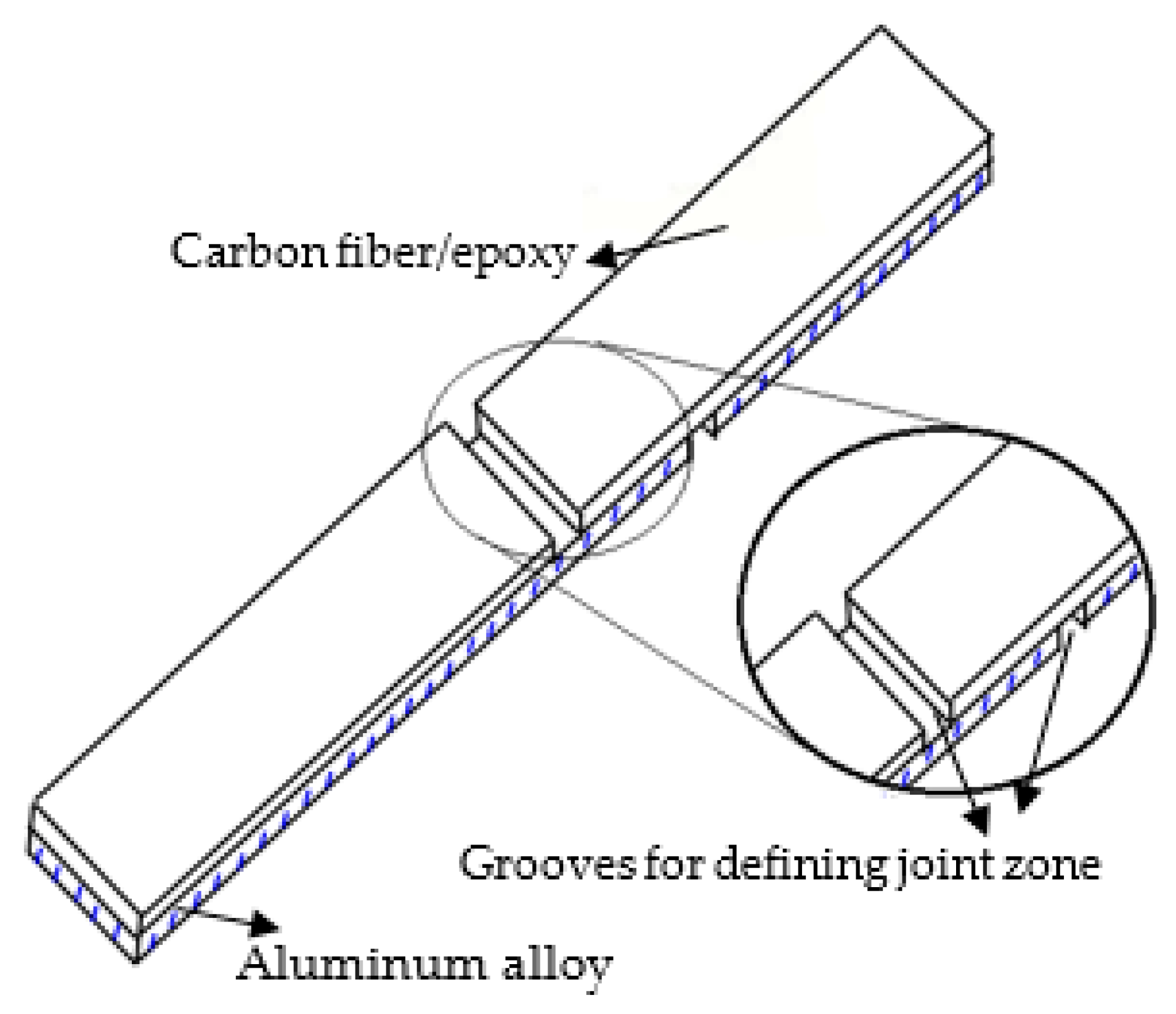
4.1. Thermal Residual Stresses

Fiber metal laminates are lightweight materials, consisting of very thin layers of metallic sheets interspersed with layers of fiber reinforced adhesives. The engineering aim behind the design of fiber metal laminates is to combine the best properties of metals and fiber-reinforced composites. Different materials can be used to create such hybrid material systems. However, any arbitrary combinations of materials would result in poor structural quality due to the existence of difficulties, such as very high residual thermal stresses during the fabrication process, galvanic corrosion, etc., during the manufacturing of these mixed materials. Residual stresses are developed in fiber metal laminates (FML) during the autoclave curing process due to a mismatch between the coefficients of thermal expansion of fiber layers and metal layers. Several other parameters, such as thermal contraction, which arises during the post-fabrication cooling process, laminate layup, volumetric shrinkage of resin, the morphology of fibers, mold material, thermal gradient during cooling, etc., contribute to the development of these residual stresses. The undesirable effects of residual stresses are distortions of the finished components when cooled and removed from molds (dimensional stability), failure in the manufactured products (e.g., matrix cracking, interfacial failure, ply failure), etc. Such stresses can subsequently reduce the design life and durability of fiber metal laminates. Therefore, the prediction and measurement of residual stresses is important to achieve the durable performance of fiber metal laminates. Therefore, the prediction of these residual stresses was done in the above stated two FML configurations before predicting their mechanical behavior.

4.2. Thermal Residual Stresses Finite Element Analysis

A three-dimensional (3D) finite element (FE) model was developed to predict cure-induced residual stresses for tensile specimens. The three-dimensional FE package, LS-Dyna, was used for the prediction of geometrical changes of the woven carbon/epoxy composite reinforced aluminum alloys specimens. Layered solid elements with perfect bonding between the layers are used. The element formulation, ELFORM 16, with full integration has been used for both aluminum and carbon fiber/epoxy layers. Since the cool-down part is dominant in the development of distortions, this part of the cure cycle is used as a primary modeling in static simulation of residual stresses. The Ls-Dyna FE package calculates the thermal residual stresses considering a linear relationship between the thermal strain and change in temperature at every increment in simulation time. Thermal stress is calculated by using strain values at each integration point as:
σ = E · ε = E · α · Δ t  
The thermal load is ΔT, the temperature difference between ambient temperature and cure temperature. The thermal load was applied through. Thermal Load Curve keyword on the FE model. The aluminum layers were modeled using a piecewise linear plasticity model. An enhanced composite damage material model and plastic kinematic model were employed for modeling the carbon fiber/epoxy and synthetic surfacing veil layers [47]. A thermal expansion coefficient was added to both materials through an add thermal expansion material card. The contact between adjacent layers was applied using the tied surface to surface contact algorithm. Material properties are assumed to be independent of temperature during analysis and in the final (after cool down) phase. The material properties of carbon fiber/epoxy and aluminum layers used in the residual thermal stress modeling are given in Table 2 and Table 3. Finite element models developed for thermal residual stress prediction for tensile specimens are shown in Figure 12.

4.3. Tensile Finite Element Analysis

The tensile behavior of FMLs was modeled by commercially available LS-DYNA FEM software. Static analysis was performed by using an explicit time integration scheme. The development of the FE model for tensile test numerical simulations in LS-DYNA includes discretization of geometry into finite elements, modeling of a composite material, including intralaminar failure and delamination failure, modeling of aluminum material with strain-based failure criteria, initialization of predicted thermal residual stresses, and applying appropriate boundary conditions.

4.4. Discretization of Tensile FML Specimen

Hypermesh, a preprocessor for finite element mesh generation, was used to build the tensile FE model for CARALL FML configurations. Both the aluminum layers and carbon fiber/epoxy layers in the FE model were modeled with eight-node solid elements (ELFORM 2). An element length of 1.5 mm was maintained in the gauge length region and 2 mm in the grip area of tensile FE models for both FMLs. In the normal solution phase, the appropriate boundary conditions were employed to perform the tensile simulation of CARALL FML specimens. The specimens were constrained from one end in all three translation degrees of freedom and pulled from another end at a loading of 0.05 mm/s. Since the delamination failure between the carbon fiber/epoxy and aluminum layers is only observed in the gauge length region of tensile FML specimens in experimental work, the carbon fiber/epoxy layers were connected to aluminum layers by a contact automatic one way surface to surface tiebreak contact in the gauge length region, and a tied automatic surface to surface contact was used to connect the carbon fiber/epoxy and aluminum layers in the grip area. The load-displacement data were collected using LS-PrePost and Microsoft Excel software. Figure 13 describes the finite element mesh and boundary conditions adopted for the tensile simulation of CARALL FML specimens.

4.5. Composite (CFRP) Material Model

The tensile behavior of the woven carbon fiber/epoxy layers was modeled using Chang-Chang [48] damage initiation criteria inbuilt in the enhanced composite damage (Mat_054) material model of LS-DYNA. According to this failure criterion, damage in composite laminate occurs when one of the following failure equations is equal to or greater than zero. Fiber tension, fiber compression, matrix tension, and matrix compression are the four failure modes considered in the Chang-Chang failure criteria [48]. The failure equations are represented separately as follows:
Tensile failure, fiber direction:
  σ 1 > 0 e f ,   T 2 = [ σ 1 X T ] 2 + Ψ [ τ 12 S ] 1 { 0   failure < 0   elastic  
Upon failure E1 = E2 = G12 = ν12 = ν21 = 0.
Compressive failure, fiber direction:
  σ 1 < 0 e f , C 2 = [ σ 1 X C ] 2 1 { 0   failure < 0   elastic   
Upon failure: E1 = ν12 = ν21 = 0.
Tensile failure, matrix direction:
  σ 2 > 0 e m , T 2 = [ σ 2 Y T ] 2 + [ τ 12 S ] 2 1 { 0   failure < 0   elastic  
Upon failure: E2 = G12 = ν21 = 0.
Compressive failure, matrix direction:
  σ 2 > 0 e m , C 2 = [ σ 2 2 S ] 2 + σ 2 Y C [ Y C 2 4 S 2 1 ] + [ τ 12 S ] 2 1 { 0   failure < 0   elastic  
Upon failure: E2 = G12 = ν12 = ν21 = 0.
Where, σ1 is the nominal stress in the lamina in the fiber direction; σ2 is the nominal stress in the lamina in the matrix direction; τ12 is the nominal shear stress in the plane of the lamina; XT is the tensile strength of the fibers; XC is the compressive strength of the fibers; YT is the tensile strength in the transverse direction of the fibers; YC is the compressive strength in the transverse direction of the fibers; S is the shear strength; and Ψ is the shear stress correction parameter in the tensile failure mode. The value of Ψ equal to zero was considered in the finite element analysis performed in this research study.
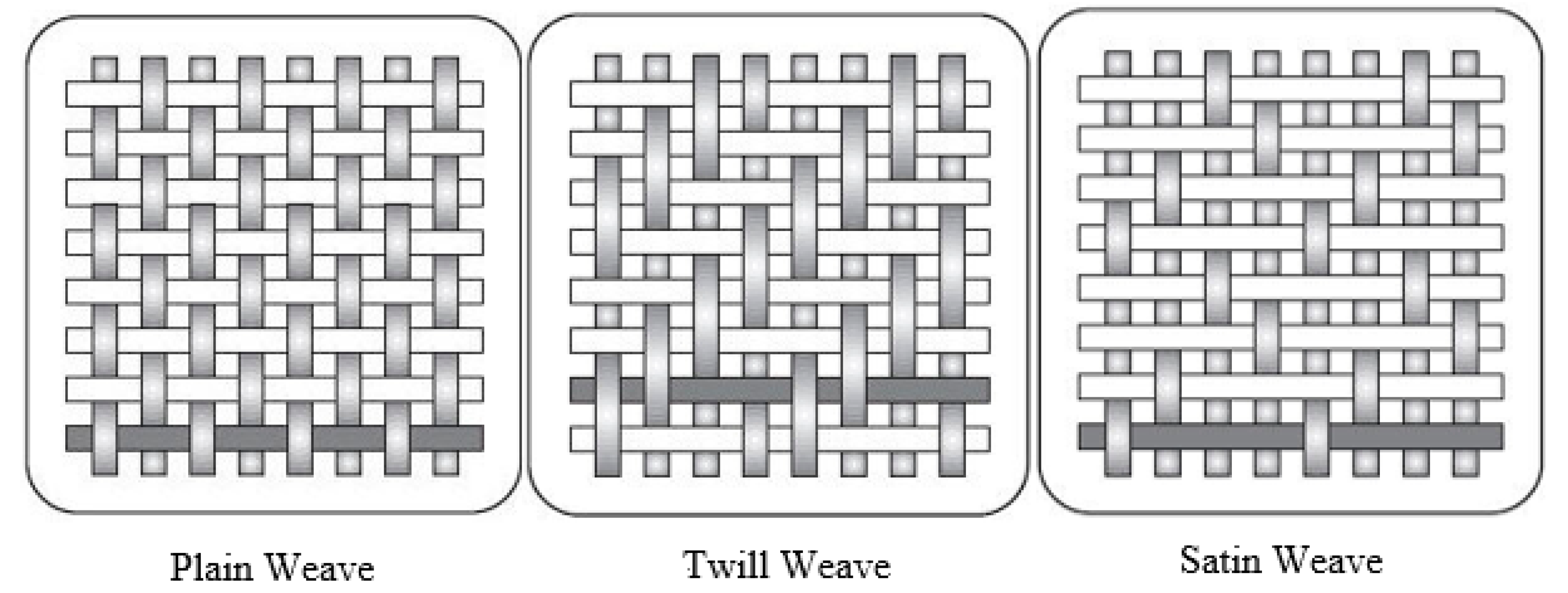
The fibers in the weft direction were also considered in the failure of the individual ply by setting up the two-way fiber flag equal to 1. When the two-way fiber flag is set equal to 1, then the failure criteria for tensile and compressive fiber failure in the local X direction are unchanged. For the local y-direction, the same failure criteria as for the x-direction fibers are used.
Tension, y direction
σ 2 > 0 e f ,   T 2 = [ σ 2 Y T ] 2 + Ψ [ τ 12 S ] 1   { 0   failure < 0   elastic  
Compressive, y direction
  σ 2 < 0 e f , C 2 = [ σ 2 Y C ] 2 1 { 0   failure < 0   elastic  
Matrix failure criterion
  e f 2 = [ τ 12 S ] 2 1  
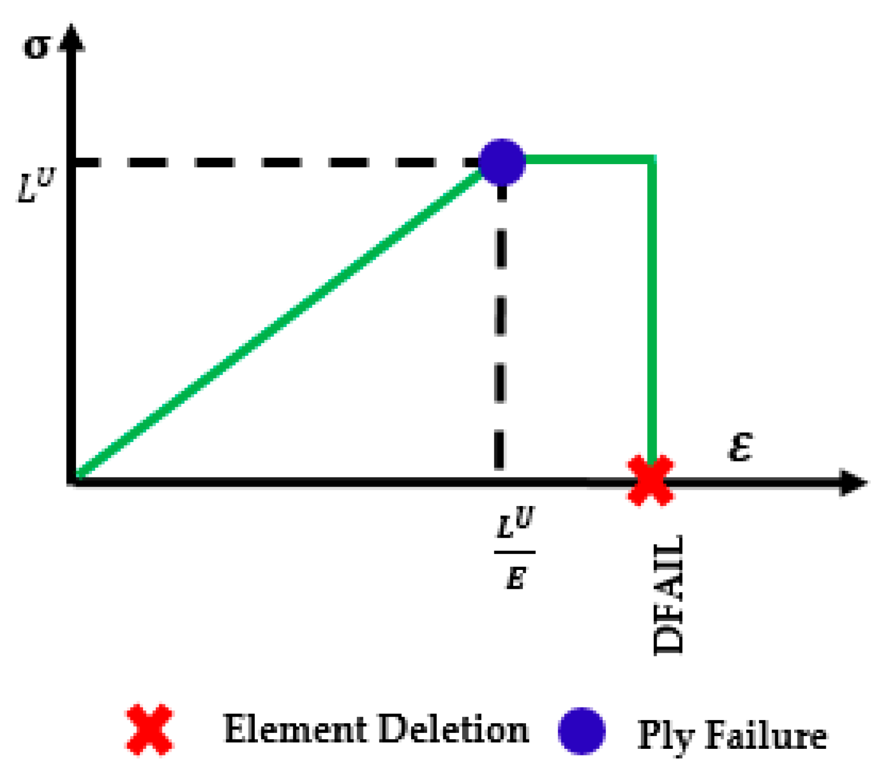
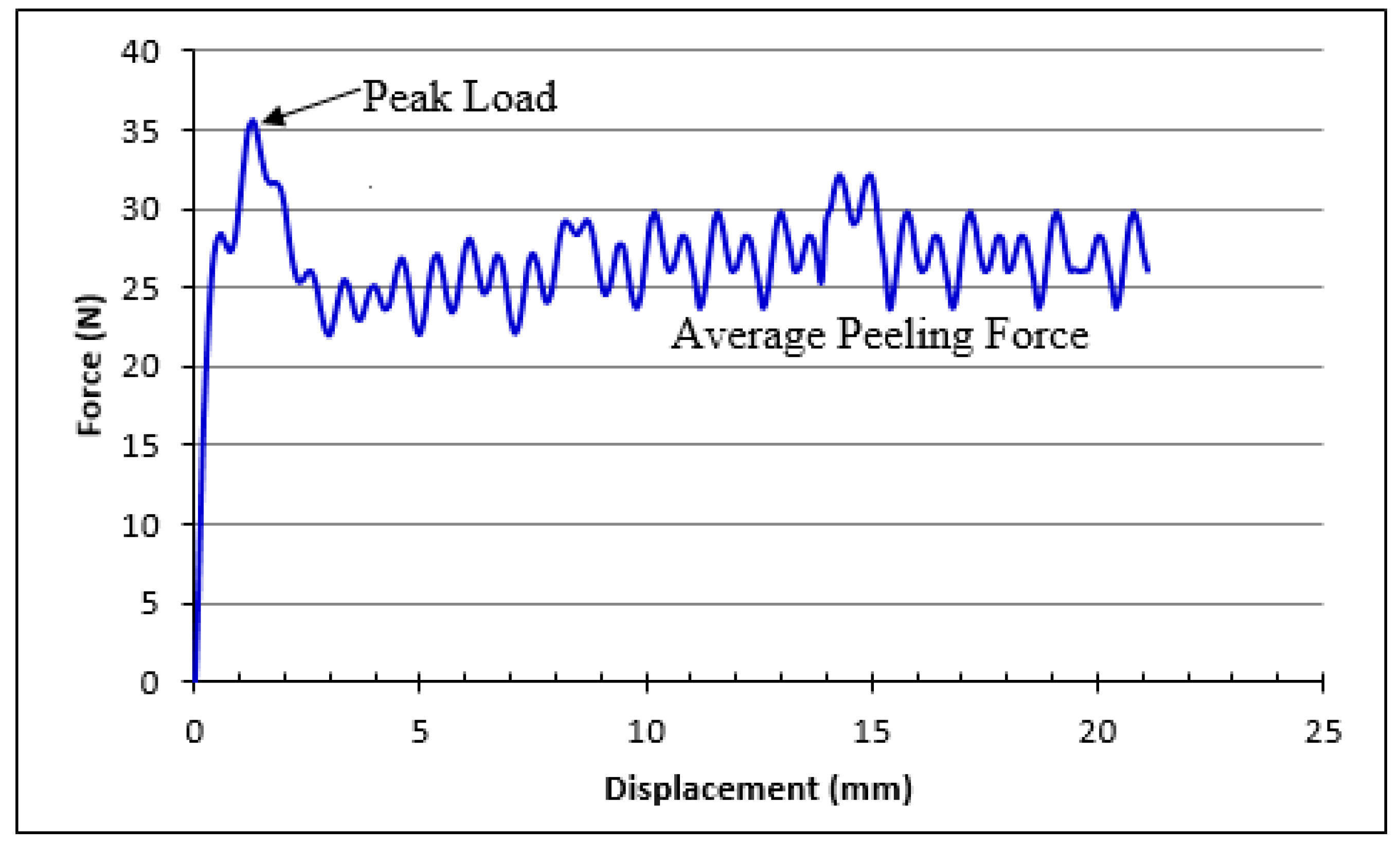
When one of the above conditions is exceeded in a ply within the element, the specified elastic properties for that ply are set to zero. The mechanism by which MAT54 applies this elastic property reduction, however, only prevents the failed ply from carrying increased stress rather than reducing the stress to zero or a near zero value. The equations used by MAT54 to determine 1- and 2-direction element stress in the ith time step provides insight into this mechanism.
  [ σ 1 σ 2 ] i =   [ σ 1 σ 2 ] i 1 + [ C 11 C 12 C 12 C 22 ] i [ Δ ε 1 Δ ε 2 ] i    
When ply failure occurs in the ith time step, constitutive properties in the stiffness matrix, C, go to zero, but the stress from the ith−1 time step is non-zero. The ply stresses of a failed ply are unchanged from the stress state just prior to failure. This produces a constant stress state in the ply stress-strain curve following failure. The resulting plastic behavior, shown in Figure 14, only occurs when the strength is reached before the failure strain. MAT54 applies property degradation following failure in this way rather than degrading properties in the elastic equations.
The MAT54’s FBRT and YCFAC strength reduction parameters are used to degrade the pristine fiber strengths of a ply if compressive matrix failure takes place. This strength reduction simulates damage done to the fibers from the failed matrix. This strength degradation is applied using the following equations:
X T   =   X T × FBRT  
X C   =   Y C × YCFAC  
The FBRT parameter defines the percentage of the pristine fiber strength that is left following failure, therefore, its value may only be in the range [0, 1]. The YCFAC parameter uses the pristine matrix strength, YC, to determine the damaged compressive fiber strength, which means that the upper limit of YCFAC is XC/YC. The input value for the two parameters, FBRT and YCFAC, cannot be measured experimentally and must be determined by trial and error. The failure equations described in Equations (2)–(8) provide the maximum stress limit of a ply, and the damage mechanisms described in Equations (9)–(11) reduce the stress limit by a specified value given specific loading conditions. None of these mechanisms, however, causes the ply stress to go to zero, as would be expected of a failed ply. Instead, five critical strain values reduce the ply stresses to zero.
These are the strain to failure values in the positive fiber direction (tension), DFAILT; in the negative fiber direction (compression), DFAILC; in the matrix direction, DFAILM; in shear, DFAILS; and a non-physical failure strain parameter called EFS. It is important to note that in the matrix direction, there is only one failure strain value, which is used for both tension and compression. When the two-way fiber flag is considered to model woven fabrics, then the DFAILT and DFAILC parameters are taken as the fiber tensile failure strain and fiber compressive failure strain in both local x and y directions. Four of the failure strains can be measured through coupon-level tests, but if they are not known, LS-DYNA gives the user the option to employ a generic failure strain parameter, EFS (effective failure strain). The EFS immediately reduces the ply stresses to zero when the strain in any direction exceeds EFS, which is given by:
EFS   = 4 3 ( ε 11 2 + ε 11 ε 12 + ε 22 2 +   ε 12 2 )  
A critical EFS value can be calculated for any simulation by determining 1-, 2-, and 12-strains at element failure, and using them in Equation (12). EFS values below the critical EFS will cause premature element deletion. The default value for EFS is zero, which is interpreted by MAT54 to be numerically infinite. An element is deleted once all of the plies in that element have zero stress. In this study, failure strains for CFRP layers were not used.

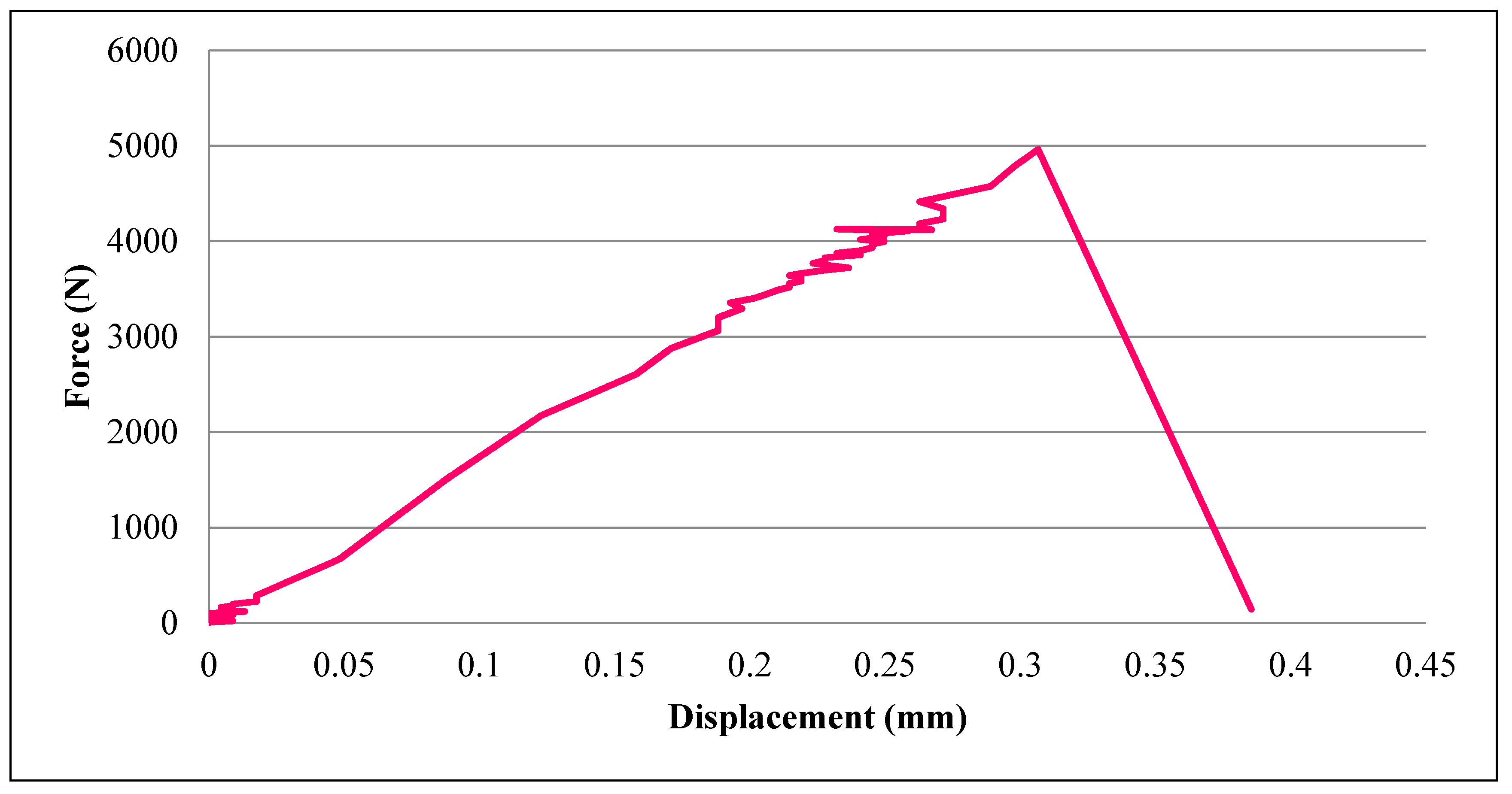
4.6. Aluminum Material Model

The piecewise linear plasticity material model (Mat_024) was utilized to model the elastoplastic behavior of aluminum layers by defining the effective stress-effective plastic strain curve obtained from experimental data. The failure of aluminum layers was modeled in this study by defining a plastic failure strain in the constitutive model card of LS-DYNA. The effective stress-effective plastic strain curve used as input to the piecewise linear plasticity material model is shown in Figure 15. The material properties’ parameters of aluminum and carbon fiber/epoxy used for predicting the tensile behavior of FMLs are presented in Table 2 and Table 3. The mechanical properties of 5052-H32 aluminum alloy shown in Table 2 were evaluated experimentally with the tensile test performed in the lab and cross-checked with the values given in reference [49].
In this material model, the plasticity treatment includes the strain rate and yield function, which is defined as:
  =   1 2   S ij S ij σ y 2 3 0   
where:
  σ y = β   [ σ 0 ] + f h ( ε eff p )  
In this material model, the hardening function,   f h ( ε eff p ) , can be defined in tabular form or specified in linear form as   f h ( ε eff p ) = E p ( ε eff p ) . The effective plastic strain is defined as ε eff p = 0 t ( 2 3 ε ˙ ij p ε ˙ ij p ) 1 / 2 dt and σ 0 denotes the initial yield strength. The plastic strain rate, ε ˙ ij p ,   is the difference between the total and elastic strain rates. The strain rate effects can be added in this model by using the Cowper-Symonds model. The yield stress is scaled in this model with the factor, β = 1 + ( ε ˙ C ) 1 / p , where C and p are the user defined input constants. The complete mathematical equations for the piecewise linear plasticity material model can be found in the LS-DYNA theory manual [50]. However, we have not used any strain rate and hardening effects in our analysis. The implementation of the piecewise linear plasticity model is done in LS-DYNA by updating the deviatoric stresses elastically, checking the yield function, and the deviatoric stresses are accepted if the yield function is satisfied. The incremental plastic strain is computed if the yield function is not satisfied.
  Δ ε eff p = ( 1.5 S ij * S ij * ) 0.5 σ y 3 G + E p   
where G and Ep are the shear modulus and actual plastic hardening modulus, respectively. The trial deviatoric stress, S ij * , state is then scaled back as:
  S ij n + 1 = σ y ( 1.5 S ij * S ij * ) 0.5 S ij *  

4.7. Delamination Failure Model

Interlaminar delamination between the carbon fiber/epoxy (CFRP) and aluminum interfaces was modeled by employing cohesive tiebreak algorithms available in LS-DYNA [51]. The transmission of both compressive and tensile forces is allowed in these penalty-based contact algorithms, which are used to model the connection between surfaces. The tie-break contact algorithms prevent the separation of the slave node from the master segment before failure of a connection, and after the failure, the contact behaves like a surface to surface contact with thickness offsets due to the removal of tensile coupling. Depending upon the nature of the connection, an optional failure criterion can be defined in all tie-break contacts. In this study, to simulate interlaminar debonding, the CONTACT AUTOMATIC SURFACE TO SURFACE TIEBREAK—DYCOSS Option 7 was chosen [52,53,54]. The cohesive contact criteria in this tiebreak contact algorithm are based on the bilinear constitutive traction-separation law. The linear elastic/linear softening model for mode 1 crack opening is shown in Figure 16. The stress-strain assumption with key points and the corresponding points with delamination progression are shown in Figure 16a,b. As point 1 is in elastic part of the material response, no material damage had occurred at this point and the unloading would follow the elastic line. The onset of damage is represented by point 2, and material softening (damage growth) starts at the point. When the loading had progressed to point 3, the material has suffered some damage, but the plies have not separated yet (damage parameter (α) is greater than zero, but less than 1). The unloading is assumed to follow the start line from point 3 to 0 if it occurs at point 3. Non-recoverable energy dissipated to partial damage of bonding is represented by the shaded area in 
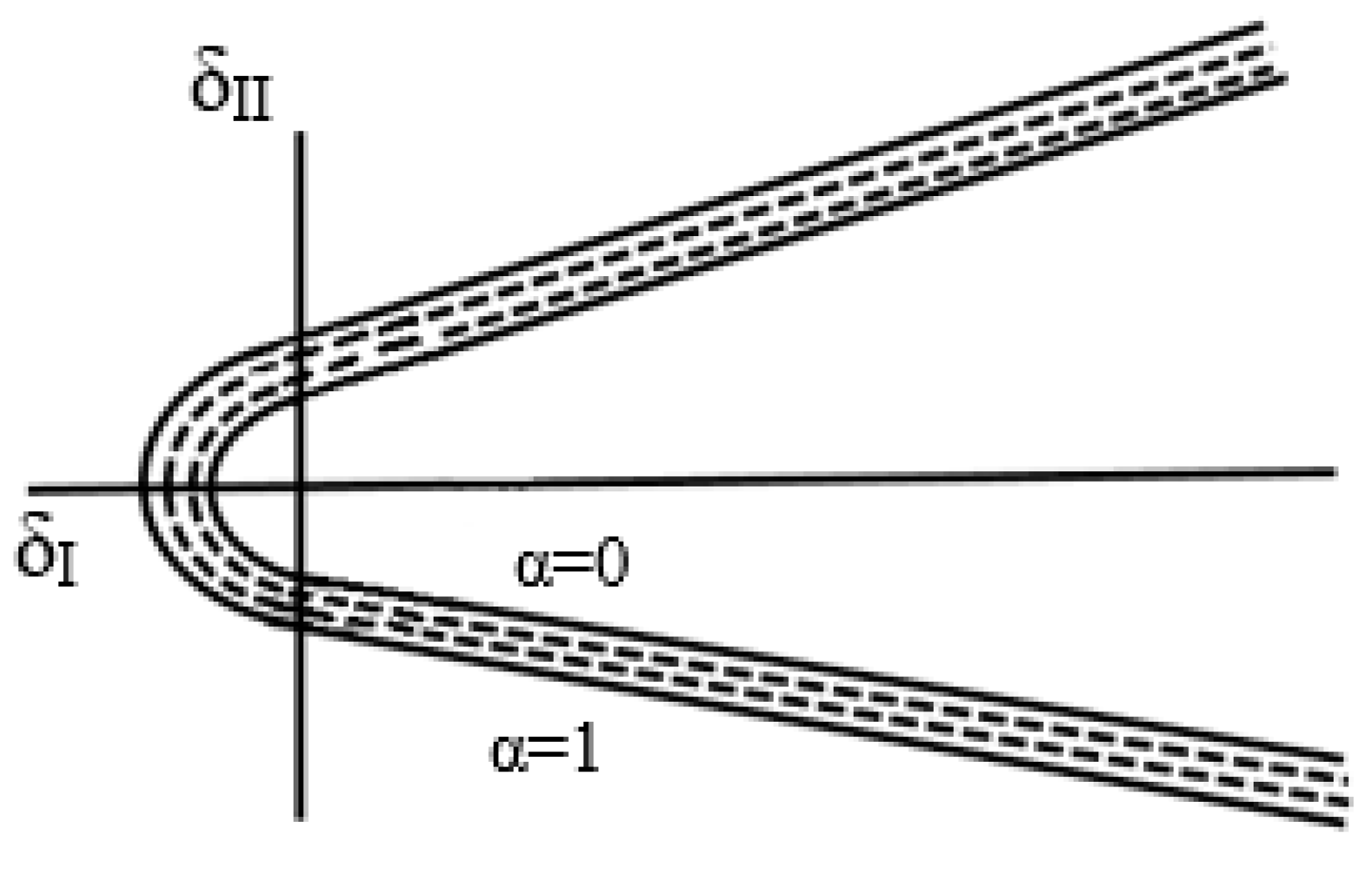
Figure 16b. The plies have separated permanently at point 4 as the damage parameter (α) had reached unity. Fracture energy (G) required to delaminate two plies is represented by the total area of the triangle (0-2-4). The input parameter in LS-DYNA has energy/area as units.
In the DYCOSS discrete crack model, the interface forces in the uncracked state (point 1) are calculated from the relative displacements assuming linear elastic behavior.
  σ = { σ I σ II } = [ k I 0 0 k II ] { δ I δ II } = K δ  
where σ I and σ II are the stresses in mode I and mode II, k I and k II are secant stiffness terms for mode I and mode II, and δ I and δ II are the displacements for mode I and mode II. The allowable shear stresses may increase under increasing normal stress for heavy woven fabrics laminate. The relation for the crack initiation, in this case, is developed by extending the Hashin criterion with a friction angle (Φ) given as:
  f = [ max ( σ I , 0 ) NFLS ] 2 + [ σ II SFLS sin ( Φ ) min ( 0 , σ I ) ] 2 = 1  
where NFLS is normal failure stress, SFLS is the shear failure stress, and Φ is the friction angle in degrees. When the loading is beyond the crack initiation point, the degradation of material is described by considering two damage variables, D I and DII.
  { σ I σ II } = [ 1 D I 0 0 1 D II ] [ k I 0 0 k II ] { δ I δ II }  
where 1-D is the stress reduction factor. The value of D ranges from 0 to 1. Damage evolution in mode I depends on displacement, δ I , only. The concept of friction angle is extended in the damage growth process for compressive normal displacements resulting in iso-lines, α, in δ I δ II planes, as shown in Figure 17.
The relation for crack propagation in terms of the internal parameter, α, is given as:
  f = [ max ( σ I , 0 ) NFLS   ( α ) ] 2 + [ σ II SFLS ( α ) sin ( Φ ) min ( 0 , σ I ) ] 2 = 1   
The interface stresses are expressed in terms of interface displacements as:
  σ I = k I ( α ) δ I   ;     σ II = k II ( α ) δ II                  
From Figure 18:
  NFLS ( α ) = k I ( α ) ( α δ I , CR + δ I 0 ) ;   SFLS ( α ) = k II ( α ) ( α δ II , CR + δ II 0 )  
  δ I ,   CR = δ I F δ I o ;   δ II , CR   = δ II F δ II o    
The initial and final displacement for mode I and mode II are given as:
  δ I 0 = NFLS k I ( 0 )   ;   δ I F = 2 G I A NFLS ; δ II 0 = SFLS k II ( 0 )   ;   δ II F = 2 G II A SFLS   
Substituting Equations (19) and (20) into (18), we get:
  [ max ( 0 , δ I ) ( α δ I , CR + δ I 0 ) ] 2 + [ δ II ( α δ II , CR + δ II 0 ) ( 1 sin ( Φ ) ) k I δ I ] 2 = 1  
The above equation is a nonlinear equation between α and known interface displacements. Linearizing it with respect to α gives:
  d α = 1 2 [ ( max ( 0 , δ I ) ) 2 δ I , CR ( α δ I , CR + δ I 0 ) 3 ] + 2 [ ( δ II ) 2 δ II , CR ( α δ II , CR + δ II 0 ) 3 ]      
After α is calculated, the secant terms are obtained as:
  k I = ( 1 α ) δ I 0 ( α δ I , CR + δ I 0 ) k I , ini   ; k II = ( 1 α ) δ II 0 ( α δ I ,   CR + δ II 0 ) k II , ini    
The damage matrix is given as:
  D = [ D I ( α ) 0 0 D II ( α ) ] = [ α ( δ I , CR + δ I 0 ) ( α δ I , CR + δ I 0 ) 0 0 α ( δ II , CR   + δ II 0 ) ( α δ II , CR + δ II 0 ) ]    
The interface stresses for the crack development state are given by:
  σ = { σ I σ II } = [ 1 D I ( α ) 0 0 1 D II ( α ) ] [ k I 0 0 k II ] { δ I δ II } = ( 1 D ) K δ  
The complete mathematical equations for the DYCOSS discrete crack model can be found in Lemmen and Meijer’s technical paper [56]. In this study, the mode II failure condition was considered dominant for modeling interlaminar delamination crack growth in an area located locally underneath the loading pin. Therefore, only shear failure strength (SFLS) = 15 MPa and shear energy release rate (ERATES) = 0.23 MPa·mm was used as input to the delamination model. Due to the lack of available data, the mode II energy release rate value was assumed.

4.8. Predicted Thermal Residual Stresses Initialization

The thermal residual stress, which comes into picture during the curing process of laminates, was initialized to the FE model with the help of the dynamic relaxation option in LS-Dyna. Dynamic relaxation is carried out before the explicit analysis in LS-Dyna i.e., in pseudo time before the actual simulation time. The simulation time resets to zero after the initialization state is achieved and the normal stage of the solution automatically begins from the initialized state. Dynamic relaxation allows LS-Dyna to approximate solutions to linear and nonlinear static or quasi-static processes. Control dynamic relaxation control card parameters are described in Table 5. The IDRFLG parameter in the dynamic relaxation control card controls the way the preloaded state is computed. If IDRFLG is set to 1 or −1, a transient “dynamic relaxation” analysis is started, in which an explicit analysis is performed and the DRFCTR factor is used to damp by means of scaling nodal velocities in each time step. When the ratio of current distortional kinetic energy to peak distortional kinetic energy (the convergence factor) falls below the convergence tolerance (DRTOL) or when the time reaches DRTERM, the dynamic relaxation analysis stops and the current state becomes the initial state of the subsequent normal analysis. Distortional kinetic energy is defined as the total kinetic energy less the kinetic energy due to rigid body motion. Distortional kinetic energy history computed during the dynamic relaxation phase is automatically written to a file called “relax”. This file can be read as an ASCII file by LS-PrePost and its data plotted.
The relax file also includes a history of the convergence factor. Dynamic relaxation was invoked by setting the SIDR parameter to 1 in the define curve commands. Curves so tagged are applicable to the dynamic relaxation analysis phase. Curves with SIDR set to 0 or 2 are applicable to the normal phase of the solution. At the completion of the dynamic relaxation stage and before the start of the normal solution stage, a binary dump file (d3dump01) and a “prescribed geometry” file (drdisp.sif) were written by LS-Dyna. Either of these files can be used in a subsequent analysis to quickly initialize the preloaded state without having to repeat the dynamic relaxation run.

5. Results and Discussion

5.1. Double Notch Shear Test

Force-displacement plots obtained from the double notch shear test are shown in Figure 19. Shear strength calculations for the strength of the bond are shown in Table 6. This shear strength value obtained for the carbon fiber/epoxy and aluminum bond is utilized as an input parameter for the numerical modeling in LS-DYNA.

5.2. T-Peel Test

Peel strength is defined as the force per unit width required to start failure and maintain a specified rate of failure using a stress applied in a peeling mode [46]. Static strength (peak load/force to initiate failure) and average peeling force (Figure 20) were the two types of loads recorded for each test. The static strength data along with the average peeling force is shown in Table 7 for carbon fiber/epoxy-aluminum specimens. Static normal strength was considered on the basis of average peeling force rather than peak load to neglect the effect accumulated resin at the crack tip of the initial crack during bonding of hinges to the specimen

5.3. Polyester Surfacing Veil Cloth Tensile Test

The load-displacement data of the machine was converted to the stress-strain curve considering specimen geometrical dimensions. The typical stress-strain response of the polyester synthetic surfacing veil/epoxy laminate is shown in Figure 21. Elastic modulus, ultimate tensile strength, and the strain were obtained from the results. The thermal expansion coefficient data for the polyester synthetic surfacing veil was not available in the literature. So, its thermal expansion coefficient was assumed to be close to an E-glass fabric surfacing veil and this assumption was verified by calculating it with Turner’s equation, which considers the modulus of both the matrix and fibers. The subscripts, m and f, in the Turner’s equation represents the epoxy matrix and E-glass fiber.
  α v = α m k m ν m + α f k f ν f k m ν m + k f ν f   
The properties of the E-glass fiber and epoxy matrix used to calculate the thermal expansion coefficient of surfacing veil cloth is given by Table 8. The nominal values and standard deviation of the tensile properties and the thermal expansion coefficient of the polyester veil cloth is summarized in Table 9. These material properties of polyester veil cloth were used in the finite element analysis of CARALL-A and CARALL-B specimens.

5.4. Thermal Residual Stress Results

Finite element thermal residual stress predictions for CARALL-A & B tensile specimens made by inserting synthetic surfacing veil cloth is mentioned in Table 10. Thermal residual stress also shows the effect of the addition of synthetic surfacing veil cloth layers. Residual stresses are increased in aluminum layers whereas they were reduced in carbon fiber/epoxy layers with the addition of polyester veil layers. Figure 22 and Figure 23 exemplifies the Finite Element Analysis (FEA) X stress predictions contours of CARALL-A & CARALL-A with veil layers specimens and CARALL-B & CARALL-B with veil layers specimens, respectively.

Effect of Polyester Synthetic Surfacing Veil Cloth Layers on Tensile Behavior

FML’s tensile properties are greatly influenced by their individual components. Composite and metal layers are loaded elastically in a first linear part of the bilinear stress-strain curve. So, FML configurations exhibit a well-defined elastic response from the composite layers and aluminum up to 0.2% strain in tensile stress-strain curves. The change in the slope after the first linear portion is due to the yielding of the metallic layer. The stress-curve in this region exhibits a nonlinear behavior. Since the tensile behavior of the carbon fiber composite is linear elastic until fracture, the stress-strain relation becomes linear again in the second phase of the bilinear stress-strain curve, as the carbon fiber layers are still reinforcing the laminate. It is well known that in the tensile mode, the Al yields, but does not fail, until the composite layers have failed. Fiber metal laminate configurations have a combination of high stiffness and strength from the composite layer and good impact properties from the aluminum layer. The load-displacement curves were converted to the tensile stress-strain diagrams for specimens of each category. Typical stress-strain plots characterizing the tensile response of CARALL-A & CARALL-B without the veil cloth is shown in Figure 24, whereas the tensile response of both FMLs having polyester veil cloth layers in shown in Figure 25.
It can be observed from Figure 24 that the tensile strength of CARALL-B is more than CARALL-A FML. Carbon fiber/epoxy and aluminum layers fail at different strain values in both FMLs as the interface bonds are not strong enough to transfer the stresses to aluminum layers after the failure of carbon fiber/epoxy layers. Carbon fiber/epoxy and aluminum layers failed at a strain value of 0.011 and 0.078, respectively, in both configurations. The difference in the strength values of aluminum layers after the failure of carbon fiber/epoxy layers at a tensile strain level of 0.011 in both FMLs is due to the volume fraction of aluminum layers. The strength of aluminum layers is reduced to about 125 MPa in CARALL-A FMLs whereas in CARALL-B, it is reduced to 100 MPa due to a lesser volume fraction of aluminum in CARALL-B. The interface bond between the carbon fiber/epoxy lamina and the aluminum plays an important role in the transfer of stresses in FML composites as the fiber matrix interface bond plays in the carbon fiber reinforced laminate composites. The addition of polyester surfacing veil cloth makes the interface bond much stronger. This statement is attributed from the fact that in CARALL specimens made with veil cloth layers, the entire laminate failed at the same strain level, i.e., ≈0.012, due to a more efficient transfer of stresses between the different layers of laminate. Whereas in CARALL specimens made without veil cloth layers, the carbon fiber layers and aluminum layers failed at different strain values as the interfacial bond was not strong enough to transfer the tensile stresses between layers. The comparison of CARALL A specimens made with and without cloth layers shown in Figure 26 clearly supports the above statements. In addition to making the interface bond stronger, the addition of polyester veil cloth also increases the ultimate tensile strength of both CARALL FML specimens, which can be inferred by comparing Figure 24 and Figure 25.

5.5. Tensile Experimental Test and FEA Results Comparison

The correlation between experiment and finite element analysis is made by plotting stress-strain curves in the same scatter plot. FEA and experimental stress-strain curves for CARALL-A & B specimens made by not using polyester veil cloth layers are shown in Figure 27 and Figure 28. The CARALL specimens made without using polyester veil cloth layers show the linear elastic response up to a strain level of 0.1% whereas specimens made with cloth layers show an elastic response up to 0.2%. The load carrying capacity of all specimens in the linear region is around 30% of the maximum load. In the linear region, both FRP and aluminum is assumed to act as a single component.
The correlation between experimental and FEA damage morphology of CARALL-A and CARALL-B specimens made without veil cloth layers are shown in Figure 29 and Figure 30. The response observed from 0.1 or 0.2% strain to their peak strength is a result of uneven load sharing between the aluminum and carbon fiber layers due to their different poison ratios. Less ductile carbon fiber/epoxy layers bear more load as compared to high ductile aluminum layers. Similarly, Figure 31 and Figure 32 depict the correlation between FEA and experimental results for CARALL-A & B specimens made by using polyester synthetic surfacing veil cloth layers.
The maximum strength attained by CARALL-A specimens made without using cloth layers and with veil cloth layers are 325 MPa and 410 MPa, respectively. Similarly, the maximum strength attained by CARALL-B specimens made without using cloth layers and with veil cloth layers are 400 MPa and 475 MPa, respectively. After attaining the peak, the aluminum layers did not fail immediately in specimens made without using polyester veil cloth layers whereas it failed immediately in specimens made with veil cloth layers. The FEM model results showed good correlation with experimental results for all different types of CARALL specimens.
It can be clearly inferred from the fracture surfaces of experimental failed specimens that aluminum layers in FMLs of all combinations were fractured at an angle approximately equal to 65 degrees to the loading direction due to the direction of the dislocation-related slip plane and slip direction of the metal crystal [58]. The carbon fiber layers fractured almost at an angle of 90 degrees to the loading direction, showing good bonding strength between the carbon fiber and epoxy matrix. Finite element models also captured the fractured surfaces of aluminum and fibrous layers of all FMLs combinations, depicting a necking induced fracture surface for aluminum layers and 90 degrees fractured surface for carbon fiber layers. A comparison between tensile properties of both FML types and monolithic 5052-H32 aluminum alloy are tabulated in Table 11. It can be observed from the tabulated results that there is a significant increase in the tensile strength in comparison to the aluminum 5052-H32 strength for both types of FMLs whereas the modulus of FMLs and monolithic aluminum is comparatively similar. The correlation between experimental and FEA damage morphology of CARALL-A and CARALL-B specimens made with veil cloth layers are shown in Figure 33 and Figure 34.

6. Conclusions

In this research work, the experimental characterization of damage mechanisms and mechanical behavior of the carbon fiber reinforced aluminum laminates (CARALL) cured with and without using polyester synthetic surface veil cloth layers at the interfaces of carbon fiber aluminum layers under tensile loading were performed. For tensile and thermal residual stress cases, FEA models were developed for each case, which showed excellent correlation. Specific conclusions made from this investigation are listed.
● Thermal Residual Stresses
Thermal residual stresses developed during the curing of fiber metal laminates were predicted by utilizing finite element modeling. It was found that the veil cloth layer does not affect much in reducing the thermal residual stress of the entire laminate. Although the effect may be small, the tensile stress in aluminum was increased by 26.8 to 104.5 MPa, and the compressive stress in the CFRP was reduced by 46 to 95.7 MPa, resulting from the addition of the veil cloth layer in CARALL A specimens. The veil cloth layers also observed small residual stresses of 12 MPa, which were tensile stresses in nature. This difference did not show an effect on the tensile strength of the entire laminate, as the increase in tensile stress of aluminum layers was counter balanced by a reduction in the compressive stresses of the carbon fiber layers and induced tensile stresses of veil cloth layers. The total tensile stresses of the aluminum layers and veil cloth layers (27 + 12 MPa) were balanced by compressive stresses of the carbon fiber layers (46 MPa). Therefore, the entire laminate was almost in equilibrium at the initial stage with the addition of veil cloth layers. Thermal residual stress developed in aluminum layers of CARALL A (77.2 MPa) was found to be lower than CARALL B (104.2 MPa), however, the residual stresses developed in carbon fiber/epoxy layers was higher in CARALL A (140.7 MPa) laminate than CARALL B (101 MPa).
● Tensile Response Characterization
The addition of veil cloth layers led to combined failure of all layers in both CARALL laminates at the same time, whereas the carbon fiber/epoxy layers broke before the failure of aluminum layers in samples without veil cloth layers. Bonding between aluminum and carbon fiber/epoxy layers with the addition of resin rich layers did not allow the separation; therefore, the crack tended to propagate through the thickness of the material rather than manifest as delamination damage. CARALL-B FMLs showed stiffer tensile characteristics, with a high tangent modulus and small failure strain, when the carbon fiber/epoxy layers were stacked exterior to the aluminum layers as compared to CARALL-A specimens with a standard 3/2 stacking sequence. The effect of changing the position of carbon fiber/epoxy layers in carbon fiber reinforced aluminum laminates on the progressive damage failure behavior of CARALL FMLs was investigated experimentally and compared with the finite element predictions. Predicted progressive damage behavior and mechanical characteristics of CARALL FMLs under tensile loading matches well with the experimental results.

Author Contributions

G.S.D. and G.M.N. contributed to the Conceptualization, Methodology, and implementation of the research, to the analysis of the results and to the writing of the manuscript.

Funding

This research received no external funding.

Conflicts of Interest

The authors declare no conflicts of interest.

References

  1. Krishnakumar, S. Fiber metal laminates—The synthesis of metals and composites. Mater. Manuf. Process. 1994, 9, 295–354. [Google Scholar] [CrossRef]
  2. Cortes, P.; Cantwell, W. The fracture properties of a fibre–metal laminate based on magnesium alloy. Compos. Part B Eng. 2006, 37, 163–170. [Google Scholar] [CrossRef]
  3. Papakyriacou, M.; Schijve, J.; Stanzl-Tschegg, S. Fatigue crack growth behaviour of fibre-metal laminate glare-1 and metal laminate 7475 with different blunt notches. Fatigue Fract. Eng. Mater. Struct. 1997, 20, 1573–1584. [Google Scholar] [CrossRef]
  4. Cortes, P.; Cantwell, W. The tensile and fatigue properties of carbon fiber-reinforced peek-titanium fiber-metal laminates. J. Reinf. Plast. Compos. 2004, 23, 1615–1623. [Google Scholar] [CrossRef]
  5. Vlot, A.; Kroon, E.; La Rocca, G. Impact Response of Fiber Metal Laminates. Key Eng. Mater. 1997, 141–143, 235–276. [Google Scholar] [CrossRef]
  6. Dhaliwal, G.S.; Newaz, G.M. Experimental and numerical investigation of impact characteristics of the e-glass/toughened vinylester composite car hood panels. J. Dyn. Behav. Mater. 2016, 2, 484–499. [Google Scholar] [CrossRef]
  7. Dhaliwal, G.S.; Newaz, G.M. Experimental and numerical investigation of flexural behavior of carbon fiber reinforced aluminum laminates. J. Reinf. Plast. Compos. 2016, 35, 945–956. [Google Scholar] [CrossRef]
  8. Frizzell, R.; McCarthy, C.; McCarthy, M. An experimental investigation into the progression of damage in pin-loaded fibre metal laminates. Compos. Part B Eng. 2008, 39, 907–925. [Google Scholar] [CrossRef]
  9. Dhaliwal, G.S.; Newaz, G.M. Modeling low velocity impact response of carbon fiber reinforced aluminum laminates (CARALL). J. Dyn. Behav. Mater. 2016, 2, 181–193. [Google Scholar] [CrossRef]
  10. Wu, G.; Tan, Y.; Yang, J.-M. Evaluation of residual strength of notched fiber metal laminates. Mater. Sci. Eng. A 2007, 457, 338–349. [Google Scholar] [CrossRef]
  11. Glare, B.T.F. A Contribution to Aircraft Certification Issues on Strengths Properties in Non-Damaged and Fatigue Damaged Glare® Structures. Ph.D. Thesis, Delft University of Technology, Delft, The Netherlands, 2004. [Google Scholar]
  12. De Vries, T. Blunt and Sharp Notch Behaviour of Glare Laminates. Ph.D. Thesis, TU Delft, Delft University of Technology, Delft, The Netherlands, 2001. [Google Scholar]
  13. Dhaliwal, G.S.; Newaz, G.M. Compression after impact characteristics of carbon fiber reinforced aluminum laminates. Compos. Struct. 2017, 160, 1212–1224. [Google Scholar] [CrossRef]
  14. Aktas, A.; Dirikolu, M.H. The effect of stacking sequence of carbon epoxy composite laminates on pinned-joint strength. Compos. Struct. 2003, 62, 107–111. [Google Scholar] [CrossRef]
  15. Yaghoubi, A.S.; Liu, Y.; Liaw, B. Stacking sequence and geometrical effects on low-velocity impact behaviors of glare 5 (3/2) fiber–metal laminates. J. Thermoplast. Compos. Mater. 2012, 25, 223–247. [Google Scholar] [CrossRef]
  16. Dhaliwal, G.S.; Newaz, G.M. Effect of layer structure on dynamic response and failure characteristics of carbon fiber reinforced aluminum laminates (CARALL). J. Dyn. Behav. Mater. 2016, 2, 399–409. [Google Scholar] [CrossRef]
  17. Chang, P.Y.; Yeh, P.C.; Yang, J.M. Fatigue crack growth in fibre metal laminates with multiple open holes. Fatigue Fract. Eng. Mater. Struct. 2012, 35, 93–107. [Google Scholar] [CrossRef]
  18. Yeh, P.-C.; Chang, P.-Y.; Yang, J.-M.; Wu, P.H.; Liu, M.C. Blunt notch strength of hybrid boron/glass/aluminum fiber metal laminates. Mater. Sci. Eng. A 2011, 528, 2164–2173. [Google Scholar] [CrossRef]
  19. Kawai, M.; Arai, Y. Off-axis notched strength of fiber–metal laminates and a formula for predicting anisotropic size effect. Compos. Part A Appl. Sci. Manuf. 2009, 40, 1900–1910. [Google Scholar] [CrossRef]
  20. Rajkumar, G.; Krishna, M.; Narasimhamurthy, H.; Keshavamurthy, Y.; Nataraj, J. Investigation of tensile and bending behavior of aluminum based hybrid fiber metal laminates. Procedia Mater. Sci. 2014, 5, 60–68. [Google Scholar] [CrossRef]
  21. Botelho, E.C.; Silva, R.A.; Pardini, L.C.; Rezende, M.C. A review on the development and properties of continuous fiber/epoxy/aluminum hybrid composites for aircraft structures. Mater. Res. 2006, 9, 247–256. [Google Scholar] [CrossRef] [Green Version]
  22. Dixit, Y.; Begeman, P.; Dhaliwal, G.S.; Newaz, G.; Board, D.; Chen, Y.; Faruque, O. Crashworthiness performance of carbon fiber composite (CFC) vehicle front bumper crush can (FBCC) assemblies subjected to high speed 40% offset frontal impact. In Proceedings of the ASME 2017 International Mechanical Engineering Congress and Exposition, Florida, FL, USA, 3–9 November 2017; Volume 009, Topic 012. p. A004. [Google Scholar]
  23. Dixit, Y.; Begeman, P.; Dhaliwal, G.S.; Newaz, G.; Board, D.; Chen, Y.; Faruque, O. Full frontal crashworthiness of carbon fiber composite front bumper crush can (FBCC) structures. In Proceedings of the ASME 2017 International Mechanical Engineering Congress and Exposition, Florida, FL, USA, 3–9 November 2017; Volume 009, Topic 012. p. A003. [Google Scholar]
  24. Kim, J.G.; Kim, H.C.; Kwon, J.B.; Shin, D.K.; Lee, J.J.; Huh, H. Tensile behavior of aluminum/carbon fiber reinforced polymer hybrid composites at intermediate strain rates. J. Compos. Mater. 2015, 49, 1179–1193. [Google Scholar] [CrossRef]
  25. Lin, C.; Kao, P.; Yang, F. Fatigue behaviour of carbon fibre-reinforced aluminium laminates. Composites 1991, 22, 135–141. [Google Scholar] [CrossRef]
  26. Sherman, D.; Lemaitre, J.; Leckie, F.A. The mechanical behavior of an alumina carbon/epoxy laminate. Acta Met. Mater. 1995, 43, 4483–4493. [Google Scholar] [CrossRef]
  27. Lin, C.; Kao, P.; Jen, M.-H. Thermal residual strains in carbon fibre-reinforced aluminium laminates. Composites 1994, 25, 303–307. [Google Scholar] [CrossRef]
  28. Lawcock, G.; Ye, L.; Mai, Y.-W.; Sun, C.-T. The effect of adhesive bonding between aluminum and composite prepreg on the mechanical properties of carbon-fiber-reinforced metal laminates. Compos. Sci. Technol. 1997, 57, 35–45. [Google Scholar] [CrossRef]
  29. Ye, L.; Lawcock, G.; Mai, Y.; Sun, C. Effects of fibre/matrix adhesion on carbon-fibre-reinforced metal laminates. I. Residual strength. Compos. Sci. Technol. 1997, 57, 1609–1619. [Google Scholar]
  30. Hu, Y.; Li, H.; Cai, L.; Zhu, J.; Pan, L.; Xu, J.; Tao, J. Preparation and properties of fibre–metal laminates based on carbon fibre reinforced pmr polyimide. Compos. Part B Eng. 2015, 69, 587–591. [Google Scholar] [CrossRef]
  31. Botelho, E.; Silva, R.; Pardini, L.; Rezende, M. Evaluation of adhesion of continuous fiber–epoxy composite/aluminum laminates. J. Adhesion Sci. Technol. 2004, 18, 1799–1813. [Google Scholar] [CrossRef]
  32. Zhao, J.; Yang, F.; Wang, R. Ultrasonic monitoring of asymmetric carbon fiber reinforced aluminum laminates. In Proceedings of the Fourth International Conference on Smart Materials and Nanotechnology in Engineering, Gold Coast, Australia, 9 August 2013; International Society for Optics and Photonics: Washington, DC, USA, 2013; pp. 87930–87939. [Google Scholar]
  33. Botelho, E.; Pardini, L.; Rezende, M. Evaluation of hygrothermal effects on the shear properties of carall composites. Mater. Sci. Eng. A 2007, 452, 292–301. [Google Scholar] [CrossRef]
  34. Lapczyk, I.; Hurtado, J.A. Progressive damage modeling in fiber-reinforced materials. Compos. Part A Appl. Sci. Manuf. 2007, 38, 2333–2341. [Google Scholar] [CrossRef]
  35. Frizzell, R.; McCarthy, C.; McCarthy, M. Simulating damage and delamination in fibre metal laminate joints using a three-dimensional damage model with cohesive elements and damage regularisation. Compos. Sci. Technol. 2011, 71, 1225–1235. [Google Scholar] [CrossRef] [Green Version]
  36. Frizzell, R.; McCarthy, C.; McCarthy, M. Predicting the effects of geometry on the behaviour of fibre metal laminate joints. Compos. Struct. 2011, 93, 1877–1889. [Google Scholar] [CrossRef]
  37. Linde, P.; de Boer, H. Modelling of inter-rivet buckling of hybrid composites. Compos. Struct. 2006, 73, 221–228. [Google Scholar] [CrossRef]
  38. ASM Aerospace Specification Metals Inc. Available online: http://asm.Matweb.Com/search/specificmaterial.Asp?Bassnum=ma5052h32 (accessed on 16 October 2017).
  39. Advanced Composite Materials. In Aviation Maintenance Technician Handbook-Airframe; Federal Aviation Administration: Washington, DC, USA, 2012.
  40. Rattan, R.; Bijwe, J. Carbon fabric reinforced polyetherimide composites: Influence of weave of fabric and processing parameters on performance properties and erosive wear. Mater. Sci. Eng. A 2006, 420, 342–350. [Google Scholar] [CrossRef]
  41. Cytec Industrial Materials. Available online: http://cytec.Com/sites/default/files/datasheets/vtm260_series.pdf (accessed on 9 August 2018).
  42. Park, S.Y.; Choi, W.J.; Choi, H.S.; Kwon, H. Effects of surface pre-treatment and void content on glare laminate process characteristics. J. Mater. Process. Technol. 2010, 210, 1008–1016. [Google Scholar] [CrossRef]
  43. ASTM D3846–08, Standard Test Method for In-Plane Shear Strength of Reinforced Plastics; ASTM International: West Conshohocken, PA, USA, 2015.
  44. Frantz, M.; Lauter, C.; Tröster, T. Advanced manufacturing technologies for automotive structures in multi-material design consisting of high-strength steels and CFRP. In Proceedings of the 56th International Scientific Colloquium (56th IWK), Ilmenau, Germany, 12–16 September 2011; Universitätsbibliothek Ilmenau: Ilmenau, Germany, 2011. [Google Scholar]
  45. ASTM D1876–08, Standard Test Method for Peel Resistance of Adhesives (T-Peel Test); ASTM International: West Conshohocken, PA, USA, 2015.
  46. ISO 11339:2010, BSEN. Adhesives—T-Peel Test for Flexible-to-Flexible Bonded Assemblies; British Standards: London, UK, 2010. [Google Scholar]
  47. Newaz, G.; Dhaliwal, G.S. Analysis of residual thermal Stresses in metal/PMC composite systems. In Proceedings of the 29th Annual Technical Conference of the American Society for Composites, La Jolla, California, CA, USA, 8–10 September 2014; DEStech Publications: Lancaster, PA, USA, 2014; pp. 1545–1557. [Google Scholar]
  48. Chang, F.-K.; Chang, K.-Y. A progressive damage model for laminated composites containing stress concentrations. J. Compos. Mater. 1987, 21, 834–855. [Google Scholar] [CrossRef]
  49. Aluminum Alloy Data Sheet-Atlas Steels. Available online: http://www.Atlassteels.Com.Au/documents/atlas_aluminium_datasheet_5052_rev_oct_2013.pdf (accessed on 15 October 2017).
  50. LS-DYNA Version 971, Theory Manual, Livermore Software Technology Corporation. Available online: http://ftp.lstc.com/anonymous/outgoing/jday/manuals/DRAFT_Theory.pdf (accessed on 15 July 2016).
  51. Bala, S. Tie-Break Contacts in Ls-Dyna; Technical Report; Livermore Software Technology Corporation: Livermore, CA, USA, 2010. [Google Scholar]
  52. Loikkanen, M.; Praveen, G.; Powell, D. Simulation of Ballistic Impact on Composite Panels. In Proceedings of the 10th International LS-DYNA Users Conference, Dearborn, MI, USA, 8–10 June 2008. [Google Scholar]
  53. Lemmen, P.P.M.; Meijer, G.J.; Rasmussen, E.A. Dynamic behaviour of composite structures (Dycoss) failure prediction tool. In Proceedings of the 70th Shock and Vibration Symposium, Albuquerque, NM, USA, 15–19 November 1999. [Google Scholar]
  54. Meijer, G.J.; Rasmussen, E.A.; Lemmen, P.P.M.; Lemmen, R.L.C.; Palmer, D. Dynamic behavior of composite ship structures (Dycoss); tests and analyses efforts. In Proceedings of the 70th Shock and Vibration Symposium, Albuquerque, NM, USA, 15–19 November 1999. [Google Scholar]
  55. Davila, C.G.; Camanho, P.P. Decohesion elements using two and three-parameter mixed-mode criteria. In Proceedings of the American Helicopter Society Conference, Williamsburg, VA, USA, 29 October–1 November 2001. [Google Scholar]
  56. Lemmen, P.P.M.; Meiger, G.J. Failure Prediction Tool Theory and User Manual; Report 2000-CMC-R0018; Center for Maritime Engineering, Environment and Geosciences, Centre for Maritime and Mechanical Structures, TNO Building and Construction Research: Delft, The Netherlands, 2001. [Google Scholar]
  57. LS-DYNA Version 971, Keyword User’s Manual, Livermore Software Technology Corporation. Available online: http://ftp.lstc.com/anonymous/outgoing/jday/manuals/ls-dyna_971_manual_k_rev1.pdf (accessed on 15 July 2017).
  58. Carrillo, J.; Cantwell, W. Mechanical properties of a novel fiber–metal laminate based on a polypropylene composite. Mech. Mater. 2009, 41, 828–838. [Google Scholar] [CrossRef]
Figure 1. Different woven fibers weave patterns [40].
Jcs 02 00061 g001
Figure 2. (a) Woven carbon fiber/epoxy prepreg before curing. (b) Polyester synthetic surface veil.
Jcs 02 00061 g002
Figure 3. (a) Mechanical interlocking induced due to crevices produced by abrasion [42]. (b) Autoclave vacuum press machine used for curing the laminates.
Jcs 02 00061 g003
Figure 4. Carbon fiber/epoxy—aluminum laminates’ nomenclature and stacking sequence. (a) CARALL-A specimen schematic (b) CARALL-B specimen schematic.
Jcs 02 00061 g004
Figure 5. Nominal dimensions of tensile test samples.
Jcs 02 00061 g005
Figure 6. Dog bone specimen during tensile test.
Jcs 02 00061 g006
Figure 7. Schematic of the double notch test specimen [44].
Jcs 02 00061 g007
Figure 8. (a) Double notch shear test coupon; (b) coupon secured in the MTS testing machine; (c) damaged test coupon.
Jcs 02 00061 g008
Figure 9. Schematic of the T-peel specimen along with the dimensions (mm).
Jcs 02 00061 g009
Figure 10. T-Peel test being conducted.
Jcs 02 00061 g010
Figure 11. (a) Polyester surfacing veil coupon during the test and (b) damaged specimen after the test.
Jcs 02 00061 g011
Figure 12. Thermal residual stress FE model schematics of CARALL-A & B tensile specimens. (a) CARALL-B Specimen (b) CARALL-A specimen.
Jcs 02 00061 g012
Figure 13. Static tensile simulation FE model.
Jcs 02 00061 g013
Figure 14. Elastic-plastic stress-strain behavior of MAT54.
Jcs 02 00061 g014
Figure 15. Effective stress-effective plastic strain curve used as input to the constitutive material model.
Jcs 02 00061 g015
Figure 16. Bilinear traction-separation law for mode I crack in tension [55].
Jcs 02 00061 g016
Figure 17. Iso-lines of internal parameter α [56].
Jcs 02 00061 g017
Figure 18. Parameters in the softening model [56].
Jcs 02 00061 g018
Figure 19. Typical force-displacement curve obtained from the double notch shear test.
Jcs 02 00061 g019
Figure 20. Typical load-displacement plot achieved from T-peel tests of CFC-aluminum bond.
Jcs 02 00061 g020
Figure 21. Typical stress-strain response of polyester synthetic surfacing veil/epoxy laminate.
Jcs 02 00061 g021
Figure 22. X stress plots for residual stresses; (a) CARALL-A, (b) CARALL-A with veil layers.
Jcs 02 00061 g022
Figure 23. X stress plots for residual stresses; (a) CARALL-B, (b) CARALL-B with veil layers.
Jcs 02 00061 g023
Figure 24. Tensile behavior of CARALL FMLs without veil cloth layers.
Jcs 02 00061 g024
Figure 25. Tensile behavior of CARALL FMLs having polyester veil cloth layers.
Jcs 02 00061 g025
Figure 26. Comparison of CARALL A specimens made with and without cloth layers.
Jcs 02 00061 g026
Figure 27. FEA and experimental stress-strain plots for CARALL-A specimens.
Jcs 02 00061 g027
Figure 28. FEA and experimental stress-strain plots for CARALL-B specimens.
Jcs 02 00061 g028
Figure 29. FEA and experimental failed specimen of CARALL-A with no veil cloth.
Jcs 02 00061 g029
Figure 30. FEA and experimental failed specimen of CARALL-B with no veil cloth.
Jcs 02 00061 g030
Figure 31. FEA and experimental stress-strain plots for CARALL-A specimens having veil cloth.
Jcs 02 00061 g031
Figure 32. FEA and experimental stress-strain plots for CARALL-B specimens having veil cloth.
Jcs 02 00061 g032
Figure 33. FEA and experimental failed specimen of CARALL-A having veil cloth layers.
Jcs 02 00061 g033
Figure 34. FEA and experimental failed specimen of CARALL-B having veil cloth layers.
Jcs 02 00061 g034
Table 1. Chemical composition of aluminum 5052-H32 alloy [38].
Manganese (Mn) MaxSilicon (Si) MaxChromium (Cr)Copper (Cu) MaxIron (Fe) MaxZinc (Zn) MaxMagnesium (Mg)
0.10.250.15–0.350.10.40.12.2–2.8
Table 2. Mechanical properties of aluminum 5052-H32.
Propertiesρ (g/cc)E (GPa)UTS (Mpa)σy (Mpa)εeff plasticνα/°CG (GPa)Shear Strength (Mpa)
2.6870.32281500.090.3325.7 × 10−626.4138
Table 3. Twill weaves carbon fiber/epoxy properties [41].
Materialρ (kg/m3)E11 (GPa)E22 (GPa)ν21G12 (GPa)G23 (GPa)XcYcXtYtScα/°C
(MPa)
Carbon fiber16006060.50.053.902.3054056070074595−2.8 × 10⁻⁶
Table 4. Specimen notations and layup sequence for CARALL fiber metal laminates.
Specimen DesignationLayup SequenceMetal Volume Fraction (%)Laminate Thickness (mm)
CARALL AAL-CFRP-AL-CFRP-AL652.3 ± 0.08
CARALL A with Cloth LayersAL-Cloth-CFRP-Cloth-AL-Cloth-CFRP-Cloth-AL49.22.9 ± 0.1
CARALL BCFRP-AL-CFRP-AL-CFRP502.0 ± 0.03
CARALL B with Cloth LayersCFRP-Cloth-AL-Cloth-CFRP-Cloth-AL-Cloth-CFRP352.6 ± 0.12
Table 5. Parametric control card for dynamic relaxation in LS-Dyna [57].
Card12345678
VariableNRCYCKDRTOLDRFCTCDRTERMTSSFDRIRELALEDTTLIDRFLG
TypeIFFFFIFI
Default2500.0010.995infinityTSSFAC00.040
Table 6. Aluminum-carbon fiber/epoxy bond shear strength results.
S.noTest TypeLoad, P (N)Shear Stress (MPa)
1Double Notch Shear Test4555.5313.54
24061.6313.45
34960.4714.81
43187.3413.60
Table 7. Aluminum-carbon fiber/epoxy bond normal strength results.
S.noAverage Peeling Load (N)Static Strength (Mpa)
12337
22844
31855
41525
52035
Average20.839.2
Table 8. Properties of epoxy matrix and E-glass fiber used in Turner’s equation.
PropertiesCTE, α (C−1)Modulus, k (GPa)Volume Fraction, ν
Eglass Fiber10 × 10−6720.3
Epoxy matrix45.6 × 10−63.70.7
Table 9. Tensile and thermal expansion properties for the polyester veil cloth/epoxy.
Materialρ (kg/m3)E (GPa)Failure Stress (MPa)νCTE, α (C−1)
Cloth147114.5 ± 0.6240 ± 12.50.340.381 × 10−6
Table 10. Thermal residual stress predictions in tensile samples.
CARALL-ACARALL-A with VeilCARALL-BCARALL-B with Veil
Aluminum Layers (Mpa)σx77.61104.5104.9122.3
σy77.13105.6106.2126.3
τxy≈0≈0≈0≈0
Carbon Fiber/epoxy Layers (Mpa)σx−141.7−95.7−103.4−69.4
σy−140.2−109.3−104.4−75.2
τxy≈0≈0≈0≈0
Polyester Veil Cloth Layers (Mpa)σx 11.8 20.7
σy −9.4 11.5
τxy ≈ 0 ≈0
Table 11. Results of tensile experimental tests.
Property/SampleMonolithic Aluminum 5052-H32CARALL-ACARALL-BCARALL A with VeilCARALL B with Veil
Maximum tensile strength (MPa)240330385373425
Strain at CFC layers breaking point εmax (%)0.0860.01050.01040.01230.0114
Young’s Modulus, E (GPa)69.770.369.872.873.3
Density ρ (g/cm3)2.682.292.112.081.93
Specific Tensile strength (MPa/(g/cm3))79.48144.1182.46179.3220.2
Tensile strength increase as compared to AL (%)---37.560.455.477.2

