1. Introduction
Fused deposition modelling (FDM) is a type of 3D printing in which a thermoplastic filament is softened and extruded through a circular nozzle. The movement of the nozzle is controlled using a 3-axis system and facilitates deposition of the molten plastic in a controlled manner onto a print bed to produce the desired product. Thermoplastics are the preferred feedstock material and those commonly used to date for FDM are amorphous polymers or ones with limited crystallinity [
1,
2]. This is largely because amorphous polymers exhibit a low degree of shrinkage which is pivotal to the dimensional accuracy of components produced. Acrylonitrile-butadiene-styrene (ABS) and polylactic acid (PLA) are available commercially and the most commonly used FDM materials, but there would be a benefit to improving the mechanical properties. However, polymer properties can be dramatically modified by the use of additives; blending with reinforcing fibres offers a range of advantages including reductions in shrinkage and increased mechanical properties [
3,
4,
5,
6] which could support the use of semi-crystalline polymers as desirable in FDM. The addition of short carbon fibre in ABS has been shown to increase tensile strength and Young’s modulus, but decrease toughness, yield strength and ductility [
7]. Printer developments enabling the use of continuous carbon fibre in ABS and PLA have shown benefits in terms of increased tensile strength (147 MPa with ABS) and flexural strength (335 MPa with PLA) [
8,
9].
Polypropylene (PP) is a semi-crystalline thermoplastic polymer derived from propene, a relatively inexpensive by-product of the oil refining process. As propene is inexpensive, virgin PP is relatively cheap when compared to other virgin materials. As the recycled plastics industry is entirely market driven and manufacturers have generally preferred to use virgin material, the market price for recycled polypropylene is very low. Despite the high quantity of PP being used in consumer products, the low market value often has not warranted the cost of collection and sorting, resulting in a lot of the polymer going to landfill. However, as part of the broader transformation occurring with 3D printing, the shift of manufacturing into the hands of the consumer made possible through 3D printing has raised the social conscience relating to the need for manufacture to take account of sustainability and there is market-pull relating to the desire for more sustainable feedstock material. As a consequence, reduced shrinkage of recycled PP could lead to its use in FDM giving it an increased market value while simultaneously reducing landfilled plastic which would be further supported by improvement in mechanical performance. Two major types of recycled PP could be used: pre-consumer which occurs as a result of offcuts in traditional manufacturing processes, albeit in appreciable amounts and post-consumer which has been used by consumers. Although environmental and economic advantages could be obtained from pre-consumer PP, there would be greater advantages in using post-consumer (post-industrial) PP.
This paper explores the viability of using recycled post-consumer polypropylene for applications in FDM and assesses the use of natural fibres to reduce shrinkage and improve mechanical performance.
2. Materials and Methods
2.1. Post-Consumer Recycled Polypropylene Woven Bags
Post-consumer polypropylene was selected based on the premise that the polymer did not already have an end market and would otherwise be disposed of at a refuse centre.
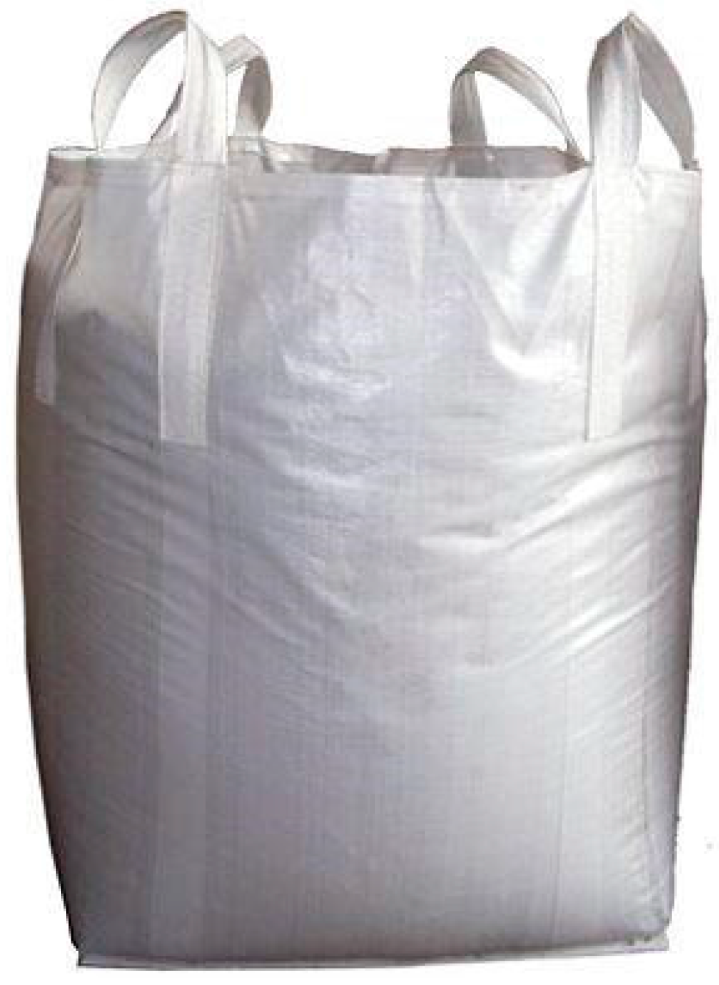
Large woven polypropylene bags, as shown in
Figure 1, were supplied by the Transpacific Recycling Centre located in Tauranga, New Zealand. These bags were a post-consumer product from a large local salt importer. This particular salt importer imports thousands of tonnes per year and the waste bags are accumulating at an increasing rate. The cleaning stage was simplified since the bags had only been used to transport salt containing very few contaminants that may adversely affect the material properties. Although there are relatively small local markets that reuse some of these bags, contamination issues restrict their use in many markets. Although the bags are predominantly made from woven polypropylene, they are stitched together using polyester thread (<1 wt %). There was no practical way to remove all traces of this thread, so the two materials were processed in a combined form. In addition to the impracticality of separation, the literature suggests possible mechanical property enhancements when combining polyester fibres in a polypropylene matrix [
10,
11,
12] and so their presence could have potential benefits. The bags were also chosen for experimentation owing to the material similarities to single use livestock feed bags. Hundreds of thousands of these are used by the New Zealand agricultural sector and are either burnt by farmers or destined for landfill.
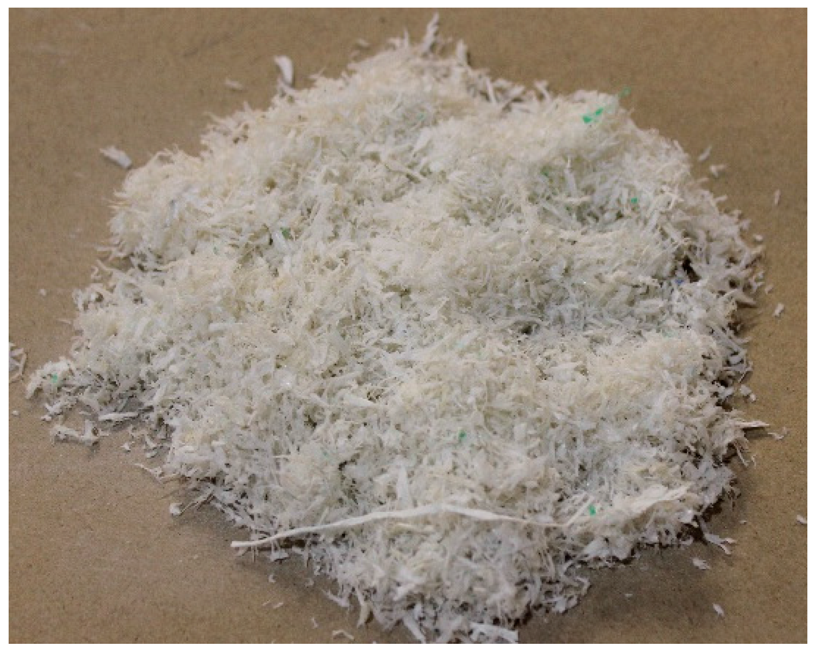
Bags were manually cut into pieces approximately 200 mm × 200 mm and then shredded using a Castin laboratory scale granulator. Salt was removed from the resulting plastic strands (
Figure 2) by washing them with dishwashing liquid in hot water before being rinsed thoroughly and oven dried at 105 °C for a minimum of 24 h.
2.2. Hemp Fibre
Hemp fibre was obtained through The Hemp Farm NZ Ltd. (Rotorua, New Zealand), having been harvested after 120 days in February 2014. Green hemp stalks were stored and air dried on shelves before the bast fibre was separated from the stalks by hand. The bast fibre was thoroughly inspected to ensure it was free of visible defects before being chopped into shorter lengths using a laboratory scale Castin granulator. An 8 mm sieve was used to regulate the size of the resultant fibre which produced an average fibre length of 10 mm.
2.3. Harakeke Fibre
Harakeke is a flax plant which is indigenous to New Zealand. The fibre has similar mechanical properties to hemp but its smaller fibre diameter could make it more suitable for applications in FDM. Mechanically separated harakeke fibre was air dried and supplied to the University in bundle form by the Templeton Flax Mill (Riverton, New Zealand) in 2014. Fibre bundles were manually cut into 200 mm lengths using scissors to avoid entanglement in the granulator blades. The chopped fibres were then fed into a Castin laboratory scale granulator using the same 8 mm sieve as used with the hemp fibre giving a similar average material length.
2.4. Coupling Agent
Maleated polypropylene (MAPP) supplied by Honeywell (AC(R)950P, Auckland, New Zealand) was used as a coupling agent with a MAPP: fibre ratio of 1:10.
2.5. Fibre Treatment
Separation of hemp and harakeke fibre was carried out using alkali treatment in a lab scale digester. Alkali treatment of natural fibres reduces average fibre diameter and removes non-cellulose constituents that do not contribute significantly to the fibres mechanical properties. Sodium hydroxide (NaOH) powder and sodium sulphite (NaSO
3) pellets, with a purity level of 98% were acquired from Scharlau Chemie S.A. (Barcelona, Spain). Oven dried hemp or harakeke fibres were weighed into 90 g samples and carefully placed into one of four steel canisters used to contain the fibre/solution mixtures inside the larger pressurized tank of the digester. For hemp fibres, a solution containing 36 g of NaOH and 684 mL of water was mixed in a conical flask. Four batches of this solution were prepared and combined with the fibres inside the canisters immediately prior to treatment. For harakeke fibres, the solution containing 36 g of NaOH, 14.4 g of NaSO
3 and 670 mL of water was prepared for use in a similar way.
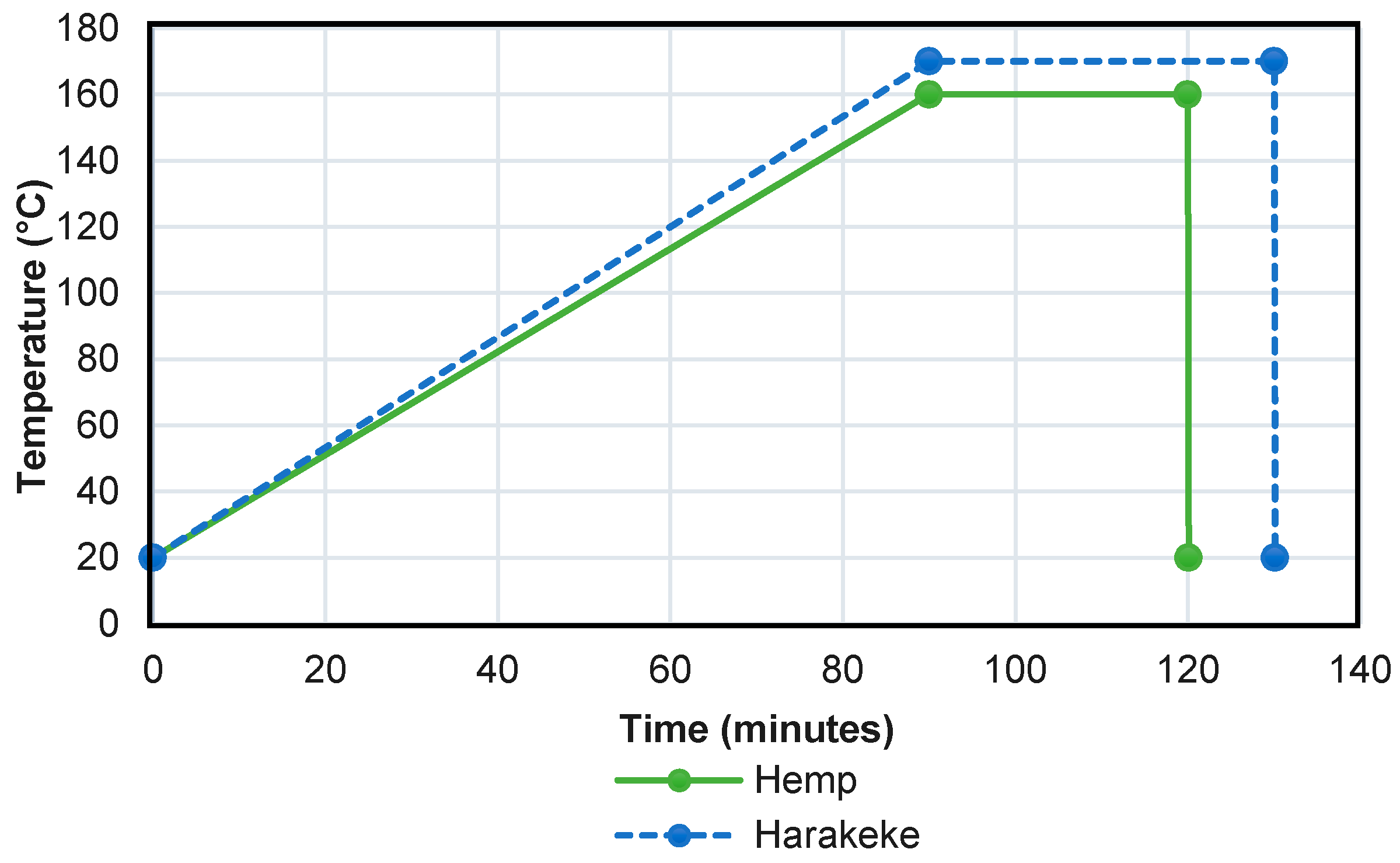
Figure 3 shows the temperature profiles used for both harakeke and hemp fibre treatment. An investigation conducted by Efendy et al. [
13] had previously determined that these treatments provided an optimal temperature profile for the aforementioned fibre species.
Once the treatment cycle was completed, fibres were removed from the canisters and thoroughly washed until all remnants of the alkali solution had been removed. The washed fibre pulp was placed in an oven to be dried at 105 °C for a minimum of 24 h. Dried fibre clusters were then put through the granulator for separation prior to composite fabrication.
2.6. Filament Fabrication
Composite constituents were weighed and placed in a sealed plastic bag where they were shaken until relatively even distribution was achieved. It was found that the use of polymer strands lead to better mixing than had been obtained with polymer granules in Part 1 [
14] of this paper. The premixed materials were then stave fed into a ThermoPrism TSE-16-TC 16 mm screw diameter co-rotating twin screw extruder (later referred to as the 16 mm extruder) (Auckland, New Zealand) with a 10 mm die before being granulated and dried at 105 °C for a minimum of 24 h. The extruder screw speed was maintained at 50 rpm with a temperature profile of 150, 170, 170, 170, 180 °C from entrance to exit. Extruded composites were allowed time to solidify before being granulated.
Granules of each different combination were stave fed at a rate of 12 rpm into a Labtech 1201-LTE20-44 20 mm screw diameter twin screw extruder (Dublin, Ireland) at 50 rpm such that the filament exited the die at approximately 0.05 m/s and was still in a semi-molten form. For dimensional control, an in-house built filament spooling machine was used (detailed in Part 1 of this paper [
14]). Composite filaments were produced containing 10, 20 and 30 wt % hemp and harakeke.
2.7. 3D Printing
The conventional method of printing onto a heated print bed was unsuccessful for polypropylene due to its lack of adhesion. A 200 mm × 200 mm × 5 mm thick polypropylene sheet was mounted in the place of the conventional heated print bed and used for all subsequent printing. Filament was printed at a temperature of 230 °C through a 1 mm die at the rate of 50 mm per minute. Single extruded rows of printed filament were used to examine the intrinsic mechanical performance of printed material.
2.8. Tensile Testing of 3D Printing Filament and Printed Material
3D printing filament and printed filament of gauge length 50 mm were tensile tested using an Instron 33R4204 universal testing machine (Instron, Norwood, MA, USA) equipped with a 5 kN load cell using a standard cross-head speed of 1 mm/min. Strain was measured for all filament using an Instron 2630-112 extensometer fitted to the samples.
Fracture surfaces of selected tensile test specimens were investigated using a Hitachi S-4100 Field Emission Scanning Electron Microscope (SEM) (Tokyo, Japan).
2.9. Shrinkage Testing of 3D Printed Parts
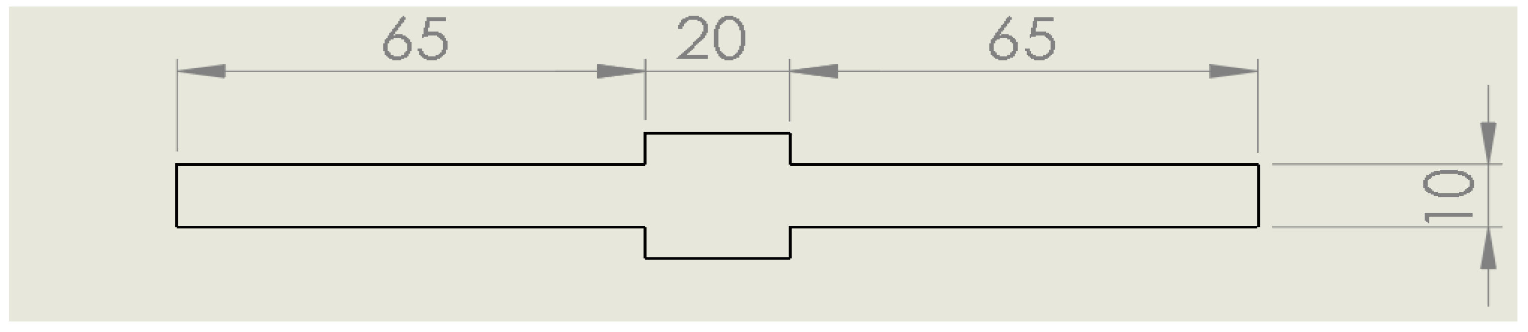
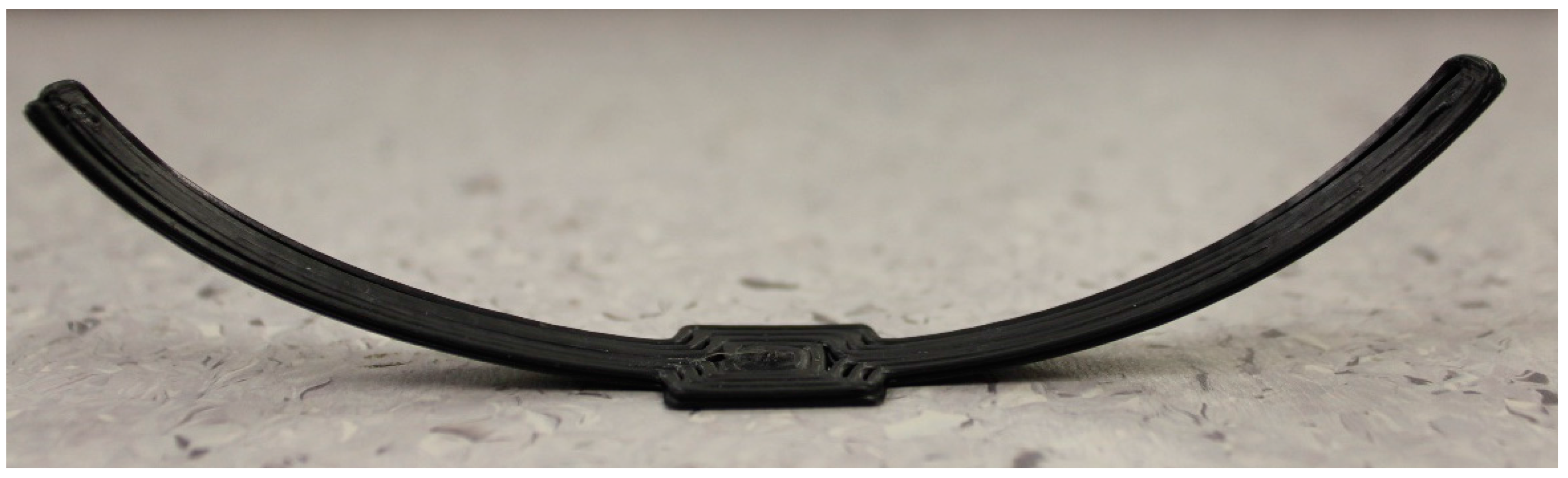
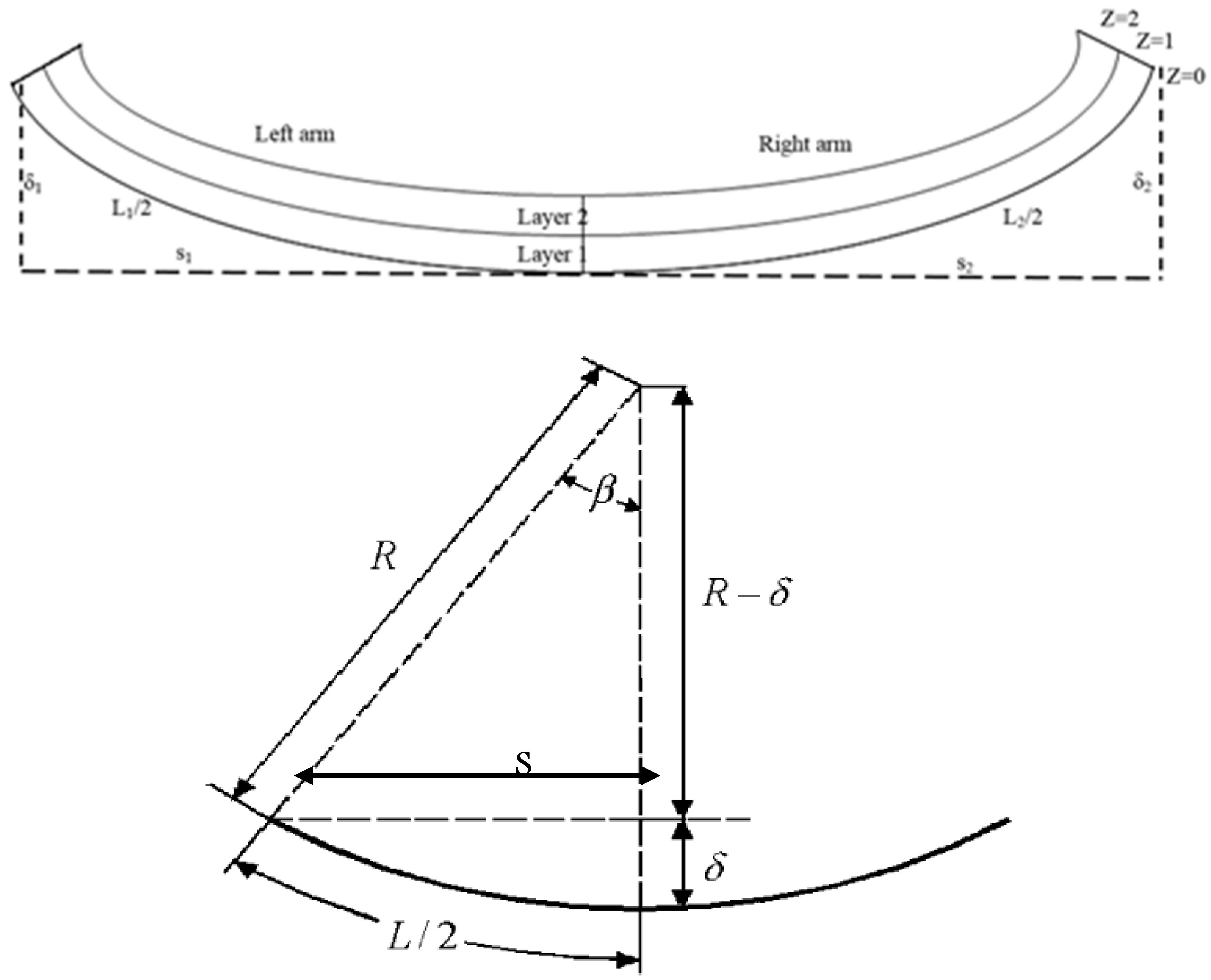
A method was developed to measure the effects of shrinkage specific to fused deposition modelling; this was based on simulation of a problem found in early testing where printed samples would peel upwards from the bed and eventually become dislodged, significantly reducing the quality of the resulting print. Test samples with dimensions as shown in
Figure 4 were printed in two layers following a concentric print pattern. The first layer (0.8 mm thick) adhered to the print bed minimising the warping effects of shrinkage. Once the first sample layer had been printed, digital calipers were used to measure the length of each arm. A razor blade was then used to dislodge the arms from the bed while leaving the centre attached. A second layer was then printed on top of the first using a vertical offset of 0.8 mm.
As the second layer solidified, its shrinkage along the length of the sample caused the sample to distort as shown in
Figure 5. The radius of curvature was used to establish a relative shrinkage value useful for comparing shrinkage properties of each material. Values used were the averages of five printed samples for each material. Full details of test sample geometry and formulas used are provided in
Appendix A Figure A1.
2.10. Density and Mass Measurements
All density values for plain polymer and composite filaments were determined using an Archimedes density test following the ASTM 792-00 standard, Standard Test Methods for Density and Specific Gravity (Relative Density) of Plastics by Displacement. The values used in the results section are the averages of five measurements which were taken using a balance accurate to ±0.5 mg.
3. Results and Discussion
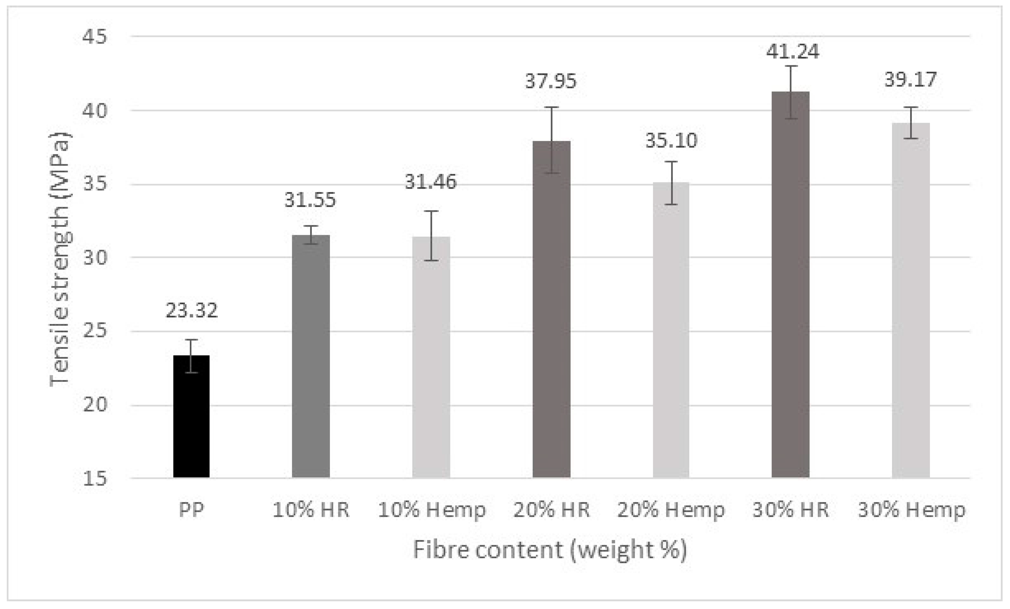
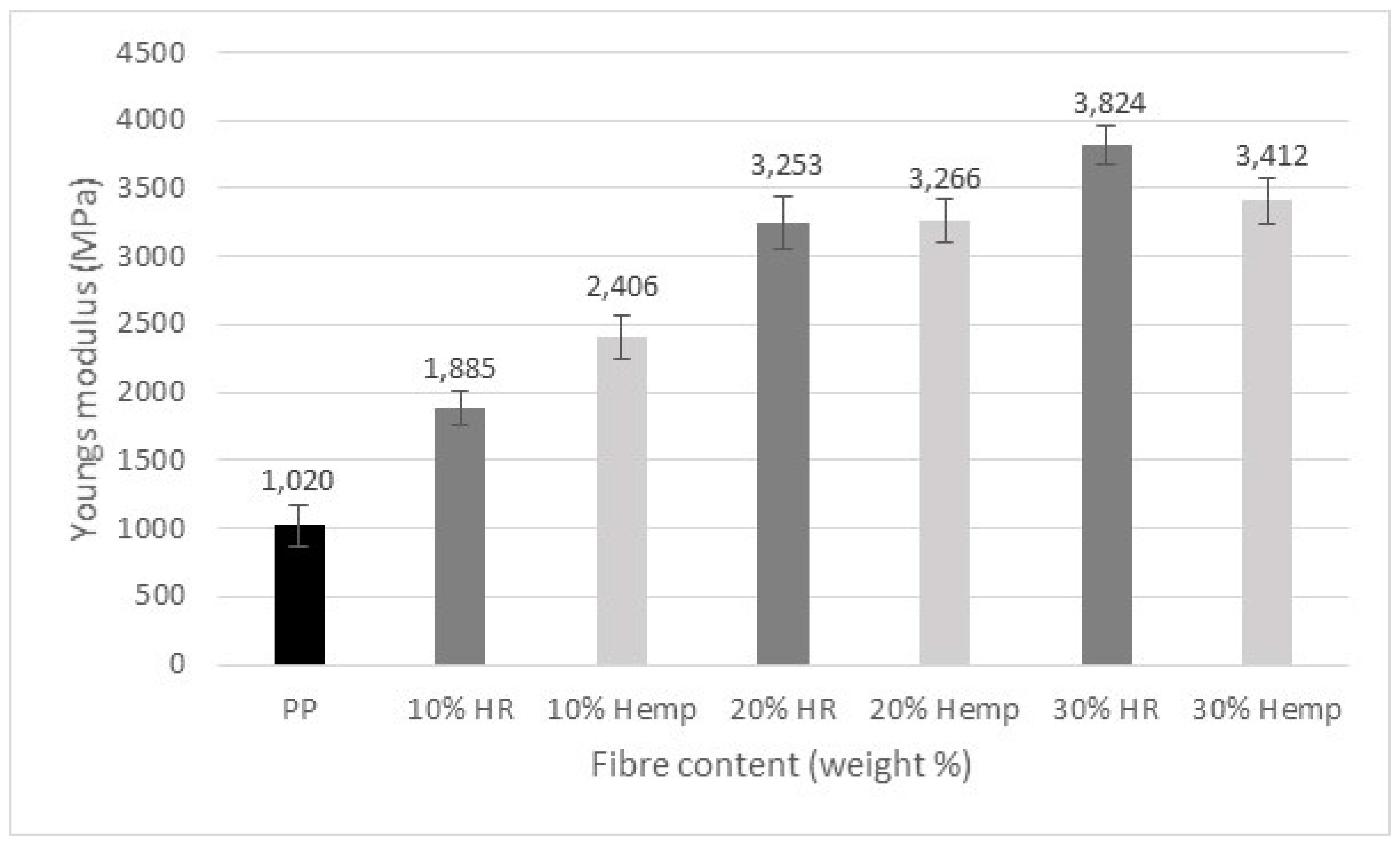
The tensile strength and Young’s modulus for PP/natural fibre composites are shown in
Figure 6 and
Figure 7. The 30 wt % harakeke samples showed the most significant improvements in strength and Young’s modulus of 77% and 275% respectively compared to plain post-consumer PP. Furthermore, values were generally higher than for those found using pre-consumer PP studied in a parallel study including that of the PP only filament which had strength and Young’s modulus values which were 6% and 14% higher than the pre-consumer PP only filament respectively [
15]. Although investigation into the different grades is necessary, the increased mechanical properties could be due to the polyester fibre content within the post-consumer polymer.
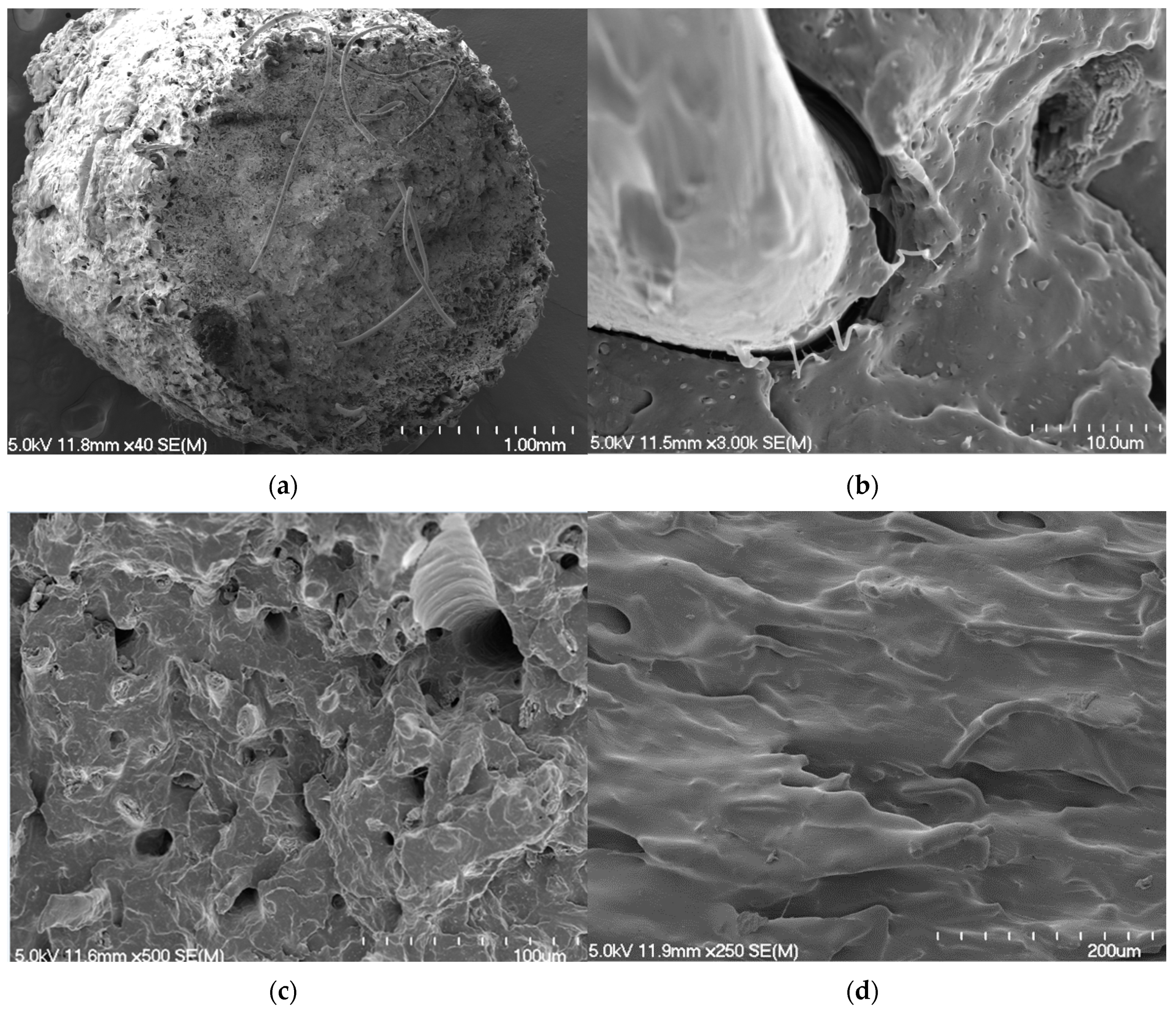
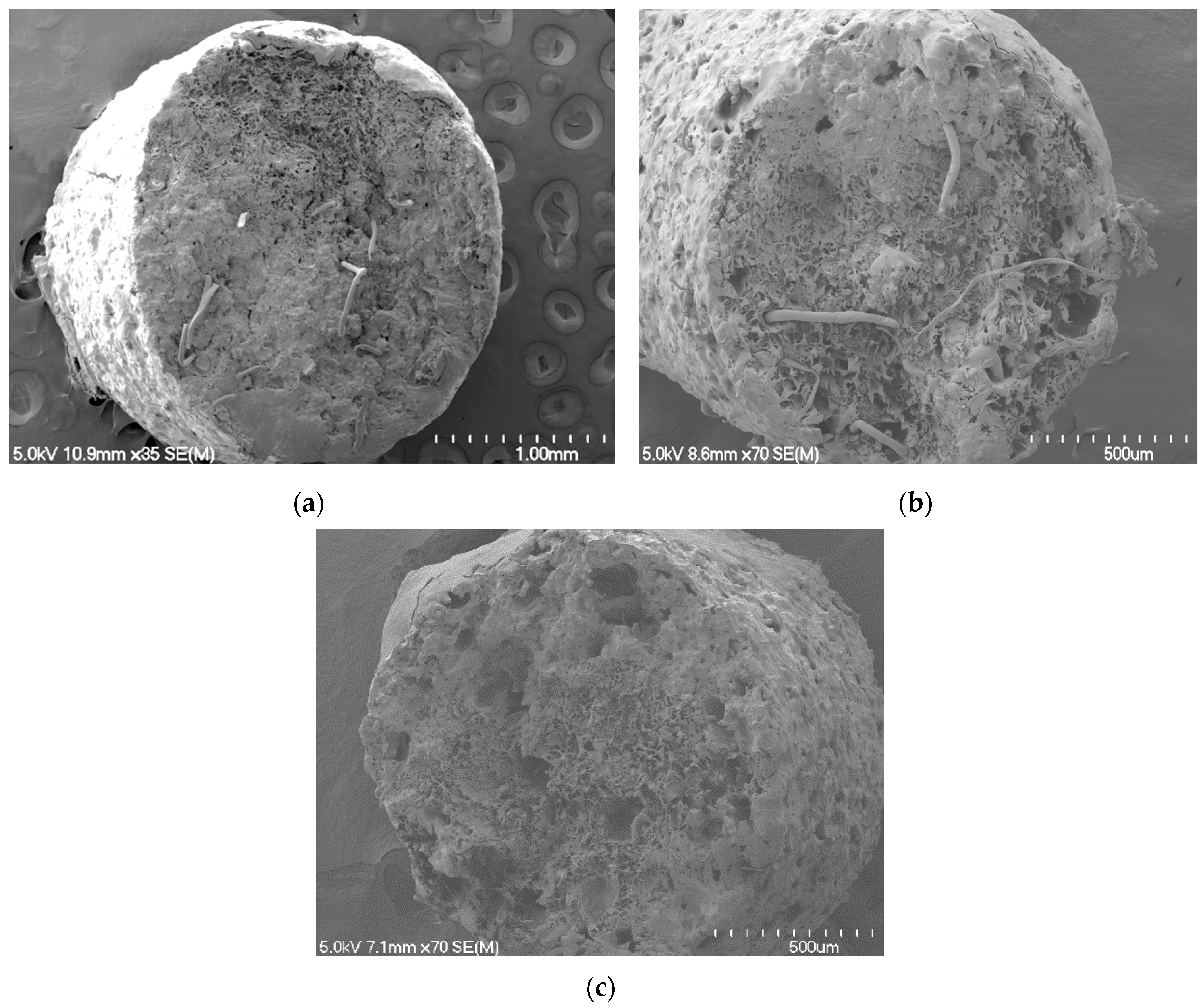
Inspection of fractured filaments evidenced long lengths of polyester fibre protruding from the fracture surfaces indicative of poor interfacial matrix adhesion between polyester fibres and the matrix (see
Figure 8a) along with a high amount of porosity which may be due to decomposition of impurities within the recycled material during manufacture. Polyester fibre could also be seen to have detached from its surrounding matrix material supporting that there had been a weak interface between them (
Figure 8b). Harakeke fibre appears better attached to the matrix supporting a stronger interface than for the polyester fibre, as well as undergoing a smaller degree of pull-out which could be due to there being at least a proportion of the harakeke fibres below the critical reinforcement length (
Figure 8c). Protruding fibre also indicated a degree of fibre alignment parallel to flow direction, further evidenced by fibre alignment seen just beneath the filament surface (
Figure 8d).
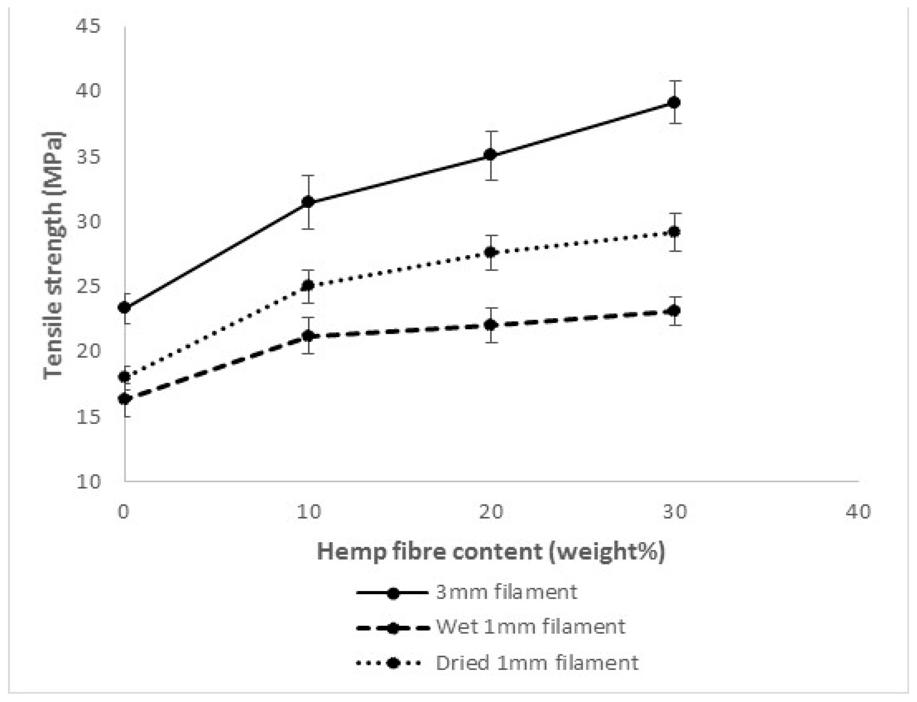
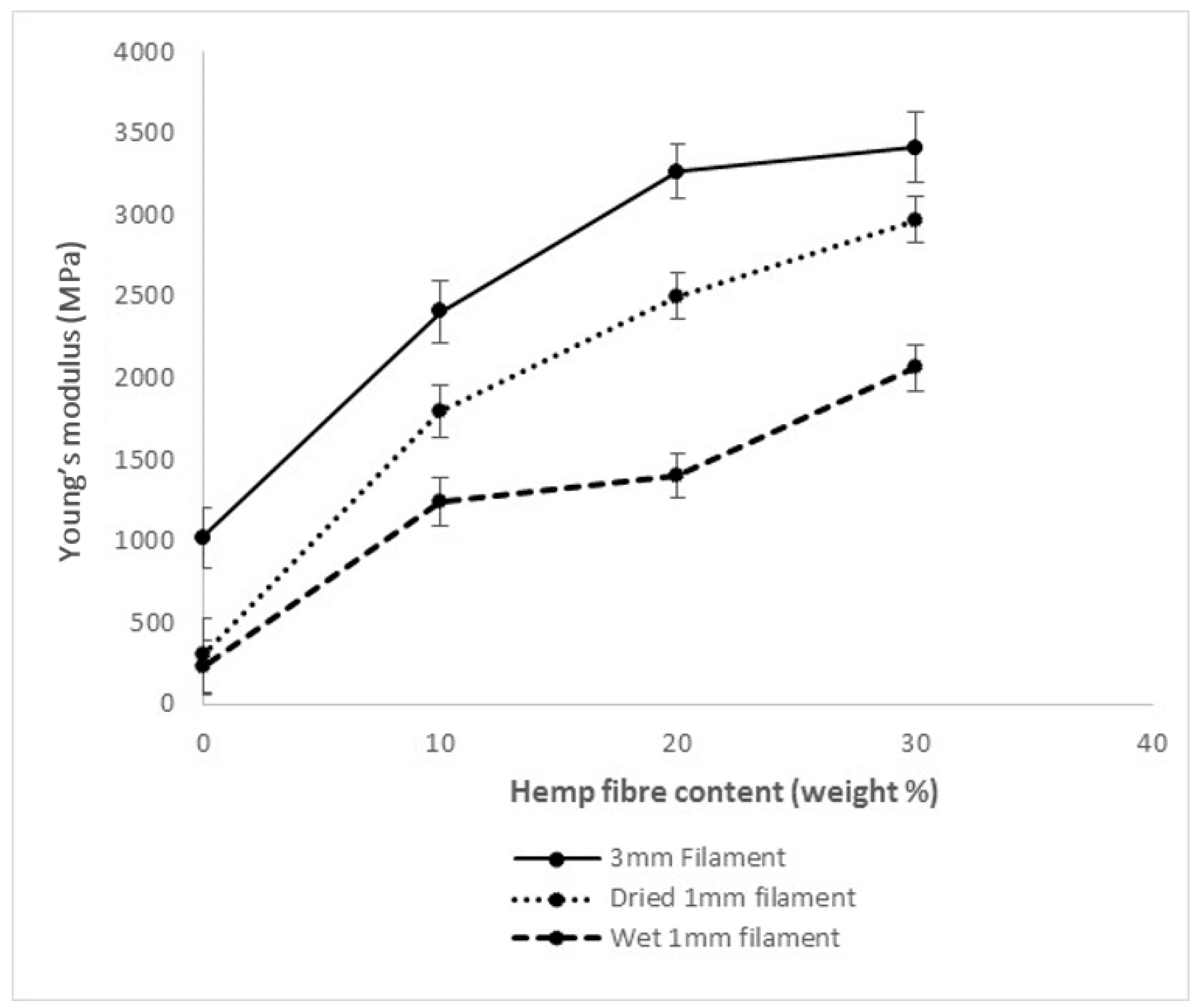
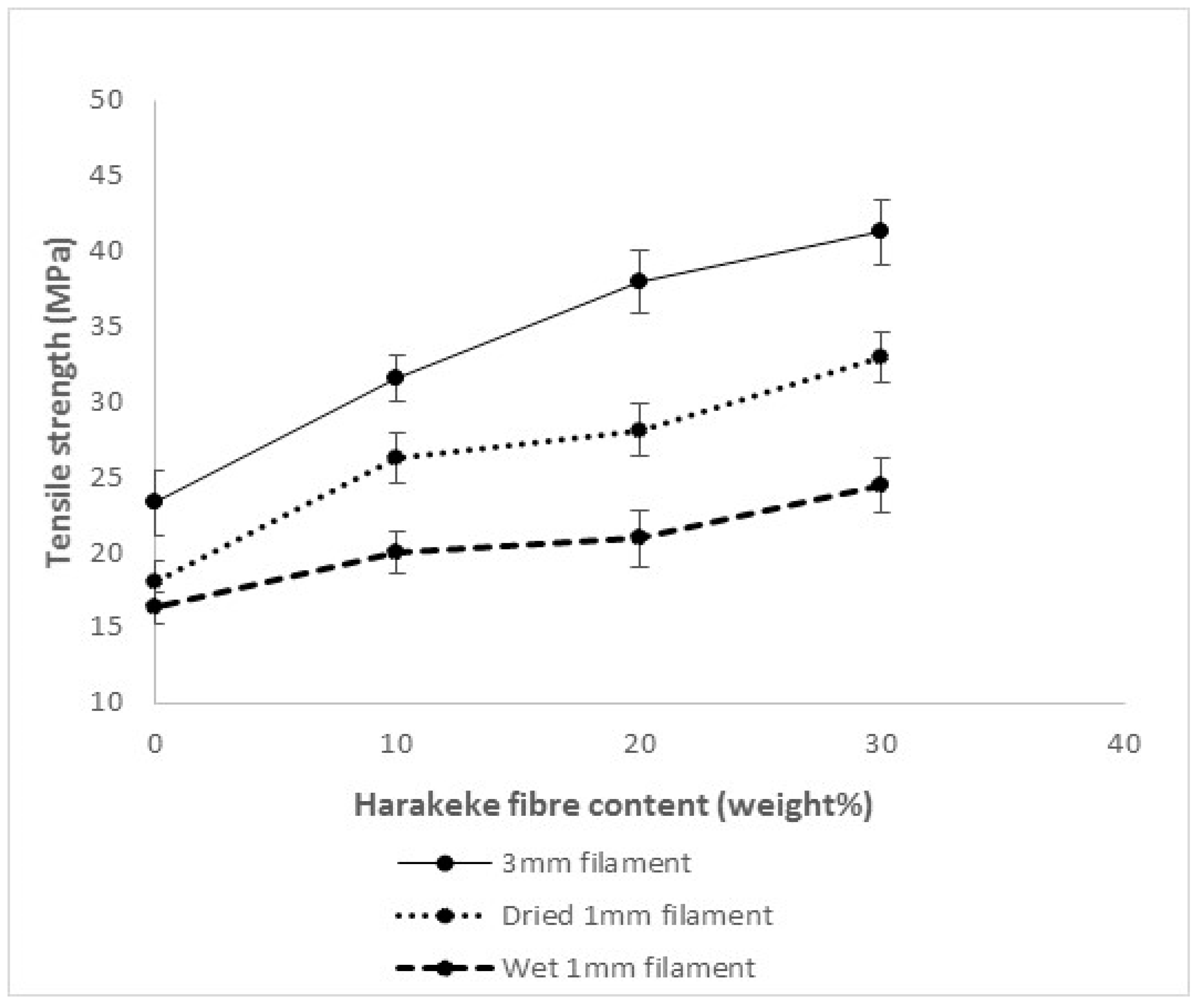
3.1. Tensile Testing of Hemp and Harakeke Fibre Reinforced Printed Material
Figure 9,
Figure 10,
Figure 11 and
Figure 12 show the strength and Young’s modulus data obtained for 1 mm diameter hemp and harakeke fibre/PP 3D printed material compared to that obtained for the 3 mm diameter printing filament. A significant reduction in properties occurred when the filaments were printed. One possible explanation was the moisture absorbed from the air into the 3 mm filament prior to printing. To investigate this further, 3D printed filament was printed after the filament was dried at 105 °C for 24 h for which the data is also shown in
Figure 9,
Figure 10,
Figure 11 and
Figure 12. A mass balance was used to measure the weights of undried and dried filament samples prior to printing, the results of which are summarised in
Table 1.
This shows a significant increase in both strength and Young’s modulus resulting from drying prior to 3D printing other than for plain PP, which is not surprising given the hydrophobic nature of the PP. The hydrophilic hemp and harakeke fibres can be considered to be the primary cause of moisture absorption. During the 3D printing process, the temperature exceeded 100 °C and would cause any moisture within the filament to evaporate. The evaporated steam could have affected the interfacial adhesion between fibre and matrix materials and/or created voids within the composite, both of which would have an adverse effect on the mechanical properties.
Although the properties increased as a result of drying feedstock material prior to printing, tensile strength and Young’s modulus values were still lower than those of the 3 mm printing filament. Therefore, the potential of reduced pressure relative to that in printing filament production was investigated as a possible factor for reducing properties during printing. To this end, density values for printing filament and dried printed filaments were obtained (See
Table 1).
Extruding the 3 mm printing filament through the 3D printer resulted in composite density reductions ranging from 11.1% to 16.5%, and although there was no obvious trend with increasing fibre content, plain polypropylene filament showed significantly lower reductions than for composite filaments. Comparing the theoretical density with the density measurement of the 3 mm composite printing filament, there is a difference ranging from a 3.3% to 9.1% reduction for the actual density. This is likely to be caused by trapped air and/or moisture within the composite.
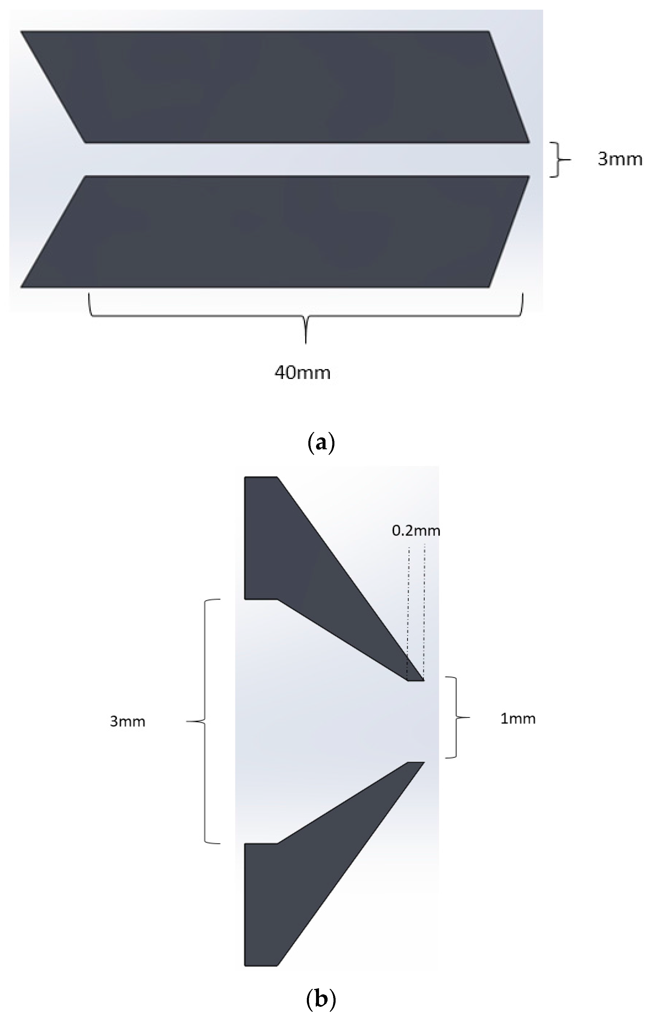
Figure 13a shows the capillary of length 40 mm which was used to produce the 3 mm diameter filament. The shear force from the walls of the filament extrusion die coupled with the partial solidification closer to the end would have induced a reasonable amount of pressure on the filament as it solidified, which would have encouraged compaction of the composite filament. The 3D printer, however, uses a very short capillary length (0.2 mm), as shown in
Figure 13b. The shorter die means that the 3D printed polymer experiences very little pressure, allowing the polymer to relax and the air/moisture to expand as it is heated and forced through the die. The reduction in density could be attributed to void formation resulting from either trapped moisture, air, or poor fibre wetting. It is possible that polymer relaxation may also be contributing to reduction of density.
Density values were used to calculate specific strength and modulus for 3 mm printing and 1 mm printed filaments.
Table 2 and
Table 3 show the differences in specific strength and modulus for 3 mm and 1 mm dry filament. When compared to the larger net differences observed in tensile strength and Young’s modulus it provides evidence that the reduction in mechanical properties is related to the density reduction of 3D printed samples, which could be due to the expansion of voids within the materials and particularly encouraged by moisture retention in fibre-reinforced composites. Expansion of voids would also be expected to increase stress concentration, and so amplify the effect of density reduction which would lead to lower specific properties. This highlights the necessity of reducing voids and moisture from FDM feedstock material.
SEM micrographs were found to support that although fracture surfaces of the 3 mm printing filament contained only small voids (
Figure 14a), those in the dried printed filament were relatively larger (
Figure 14b) compared with the printing filament, with those in the undried printed filament (
Figure 14c) relatively larger still and more plentiful.
3.2. Shrinkage
The shrinkage results for hemp- and harakeke-reinforced composites are shown in
Table 4. As the fibre content increased, the amount of shrinkage observed decreased by a maximum value of 84% for 30% harakeke. Further experimentation would be required to determine whether the presence of polyester fibre contributed to additional shrinkage reduction. However, experiments have shown that adding fibre is an effective method of reducing the effects of shrinkage in 3D printed polymers.
4. Conclusions
In this research, a series of composite 3D printing filaments were successfully extruded with varying weight fractions of hemp or harakeke fibre with post-consumer recycled PP. The strongest composite filament produced in this work contained 30 wt % harakeke fibre and had a tensile strength of 41 MPa and a Young’s modulus of 3824 MPa. These values correspond to improvements of 77% and 275% relative to unfilled recycled polypropylene filament. In addition to the natural fibre, improvements were attributed to additional reinforcement from polyester fibre present within the recycled PP.
SEM micrographs of post-consumer PP composite fracture surfaces supported very poor interfacial adhesion of polyester fibre. This was made apparent by long polyester fibres having pulled out from fracture surfaces. There was also evidence of fibre alignment along the length of the filament.
All 3D printed tensile specimens showed a drop in tensile strength and Young’s modulus relative to 3 mm feedstock. Moisture content and increased voids were found to be factors affecting reduction of properties supporting the importance of drying filament for enhanced performance and the influence of pressure on the final filament properties.
A novel method of measuring shrinkage within 3D printed components was developed and used to assess the shrinkage of different composites. The composites that displayed the greatest reduction in shrinkage contained 30 wt % harakeke with shrinkage reduction of 84% relative to un-reinforced post-consumer polypropylene. This has proven natural fibre to be an effective additive if reduced shrinkage is desired.
Based on the results shown in this research, it can be concluded that recycled polypropylene composites have the potential to be used as strong, stiff, cheap, and recyclable 3D printing filament. The rapid growth in the 3D printing industry coupled with increased environmental awareness suggest that these and similar composite filaments are highly relevant in this day and age.


