1. Introduction
Almost 30 years since its conception, additive manufacturing, or 3D printing, has gradually overcome its niche applications and is revolutionizing all manner of practices within the manufacturing industry [
1]. The remarkable ascent of additive manufacturing technology has been attributed to reductions in cost, tooling requirements, and production life cycle, when compared with traditional manufacturing techniques [
2]. To manufacture a component using this technology, computer aided design (CAD) is appropriated to develop a computerized 3D solid model of the component. The 3D CAD model is separated into 2D layered sections, allowing the geometry of each layer to be digitally analyzed. Precision machinery is used to systematically deposit each layer, generating a physical replica of the computerized model [
3]. The efficiency of this process minimizes consumption of raw material by almost 75%, leading to a reduction in carbon footprint, whilst attaining a high level of geometric accuracy [
1,
2].
The additive manufacturing industry, which incorporates machine sales, materials, and associated services, had an estimated market valuation of
$7.8 billion USD in 2014. This sector is forecasted to expand at an annual rate of around 35%, with an expected market valuation in excess of
$21.2 billion USD in 2020. Household consumers constituted 91.6% of machine sales in 2014, whilst industrial consumers accounted for the remaining 8.4% [
4].
Currently, the most widely adopted additive manufacturing technique is fused deposition modelling (FDM) [
5]. The success of FDM has largely been accredited to its simplicity, accuracy, and affordability, which has enabled the general public to become acquainted with additive manufacturing. FDM allows parts of any geometry to be constructed in layers, through the successive deposition of molten material. Thermoplastics are the preferred filament material, although a wide range of materials, including metals, ceramics, and composites, are compatible with the FDM process [
5,
6].
The rising popularity in additive manufacturing technology has coincided with increasing environmental awareness, where there is an urge to develop innovative and sustainable composites [
7]. In particular, natural fibers are becoming a preferred alternative in reinforced polymer composites, due to the energy intensive processing needed to manufacture synthetic fibers. Natural fibers are not only biodegradable and renewable, but also possess excellent tensile properties. Other than silk, which can have very high strength, but is very expensive, the best properties are obtained with plant fibers for which fiber strengths of up to 1830 MPa are reported [
8] These are generally present within plants in the form of bundles from which single fibers can be extracted by means of treatment of which alkali treatment is by far the most common. A recent review of natural fiber composites includes their mechanical properties, different treatments, and related composite mechanical performance [
9].
This paper presents the development of natural fiber reinforced polypropylene composites that are compatible with FDM processing. The literature suggests that the inclusion of natural fiber as reinforcement has yet to be investigated in FDM. The research focused on the formulation of constituent materials in order to maximize the tensile properties of composite FDM filaments and ultimately 3D printed parts.
In this investigation, two types of natural fiber were used for composite reinforcement, namely hemp (Cannabis sativa) and harakeke (Phormium tenax). Both species are abundant, relatively inexpensive to procure, and exhibit among the most favorable tensile properties of any natural fibers. Pre consumer recycled polypropylene was selected as the constituent matrix material, due to its affordable cost and minimal moisture absorption. The low processing temperature required for polypropylene also minimizes the lignocellulosic degradation of reinforcing natural fibers.
2. Experimental
2.1. Materials
Pre-consumer recycled polypropylene (PP) granules were provided by Astron Plastics, Auckland, New Zealand. Hemp fiber, locally grown in New Zealand from October 2013 and harvested in February 2014 after a 120 day cycle was provided by the Hemp Farm NZ Ltd. (Rotorua, New Zealand) Green hemp stalks were air dried for a period of two weeks before the bast fiber was separated from the stalks by hand. Harakeke fiber was mechanically prepared and supplied in bundle form by the Templeton Flax Mill, Riverton, New Zealand Maleic anhydride grafted polypropylene (MAPP) of grade AC(R)950P supplied by Honeywell was used as a coupling agent. MAPP was used due to the intrinsic incompatibilities of natural fiber and polypropylene, without it, poor interfacial bonding would result in low composite strength which can be lower than that of just the matrix [
9]. Hemp fiber and harakeke have quite different diameters with the average for hemp being approximately 35 µm and the average for harakeke being approximately 13 µm [
10]. Hemp fiber has been seen to have a higher crystallinity index (76.7) than harakeke fiber (68.5) as might be expected due to the higher structural requirements in a hemp stalk as opposed to a harakeke leaf. They have similar thermal behavior, with thermal degradation initiating at about 250 °C, although this temperature is increased by alkali treatment [
10].
2.2. Granulation of Fibres
The granulation of hemp fibers was carried out using a laboratory scale Castin granulator. An 8 mm sieve was used to regulate the size of the resultant fiber bundles which had a resulting average length of approximately 10 mm. Harakeke fiber bundles were manually cut with scissors into lengths of 200 mm and then, as for hemp fiber, granulated to give a similar average length.
2.3. Alkali Fibre Treatment
Following granulation, a laboratory scale digester was used to chemically treat the fibers with a predetermined temperature profile and time period. The chemicals used for alkali treatment (acquired from Scharlau Chemie S.A.) consisted of sodium hydroxide (NaOH) powder and sodium sulfite (Na
2SO
3) pellets, with a purity level of 98%. Ninety grams of fiber was combined with alkali solution at a fiber to solution ratio of 1:8 by weight. The alkali formulation for hemp consisted of 5 wt % NaOH, whilst a combination of 5 wt % NaOH and 2 wt % Na
2SO
3 was used for the harakeke fibers [
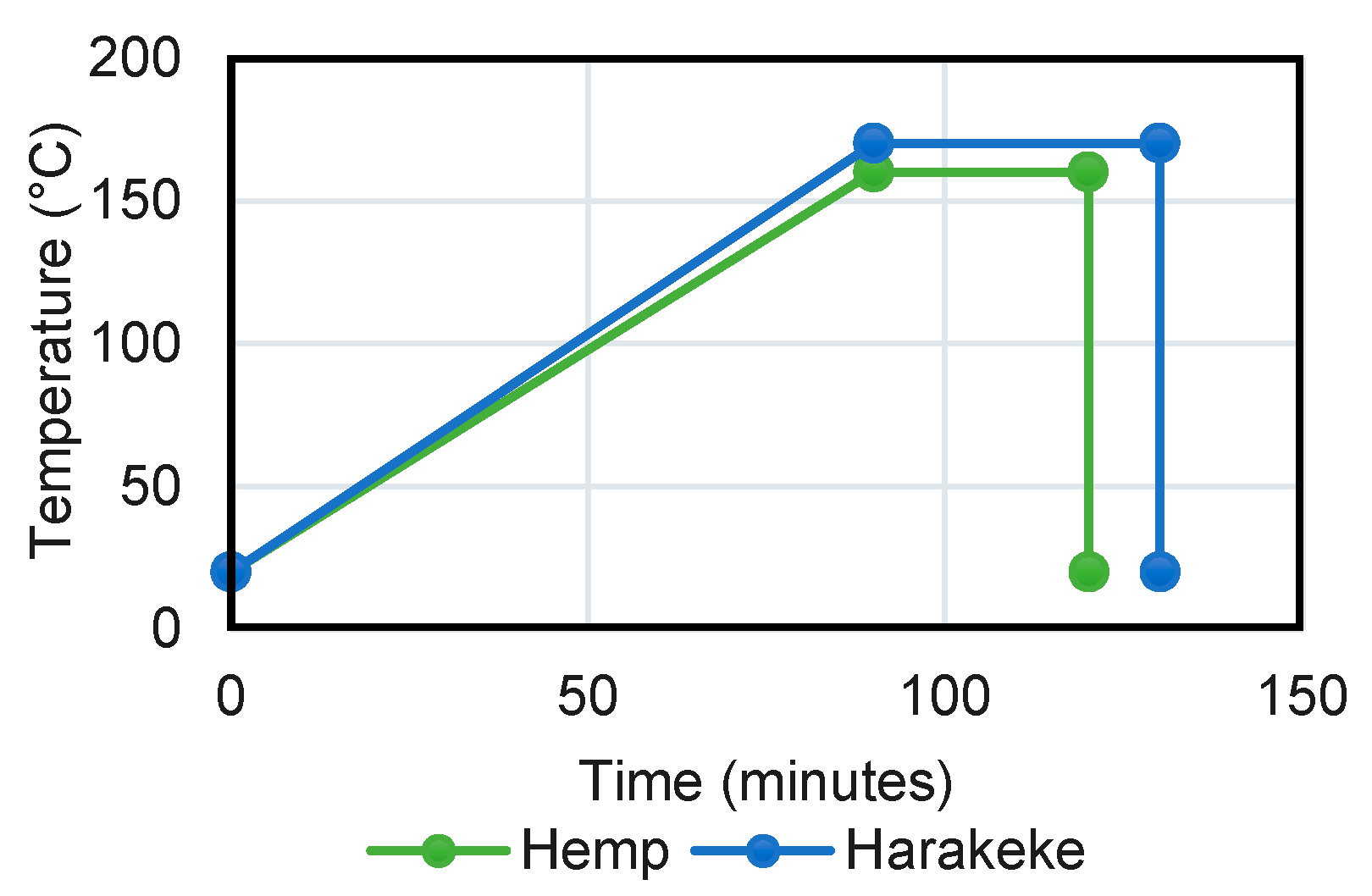
10]. The steel canisters were sealed and placed inside the lab scale digester, which followed the digestion regime outlined in
Figure 1. An investigation conducted by Efendy et al. [
10] had previously determined that these treatment regimes provided the optimal parameters for the different fibers.
Once the digestion cycle had been completed, the fibers were removed from the canisters and thoroughly washed a total of five times, or until all remnants of the alkali solution had been removed. The digested fibers were finally dried in an oven at 72 °C for a minimum period of 48 h.
Fiber diameters having undergone treatment were found to reduce from 13.0 to 12.3 (standard deviation 1.7) µm and from 34.9 to 28.3 (standard deviation 8.3) µm for harakeke and hemp, respectively [
10].
2.4. Fabrication of Filament
Prior to mixing, polypropylene granules were dried in an oven at 72 °C for a minimum period of 48 h. Compounds were prepared by weighing hemp and harakeke fibers and polypropylene granules to give 10–30 wt % fiber contents along with 2 wt % MAPP. This content of MAPP was based on previous work with hemp showing good improvement of strength for composites containing 2 wt % MAPP and little improvement at higher contents.
A ThermoPrism TSE-16-TC twin screw extruder with a 10 mm diameter die was used for mixing. Polypropylene, MAPP, and natural fibers were manually scooped into the same extruder hopper by hand. The temperature profile from the in-feed to outlet was maintained at 168 °C, 185 °C, 209 °C, and 196 °C for all composite weight percentages. A screw speed of 75 ± 10 rpm and a torque ranging from 45 to 70% was used. Hemp and harakeke composites of 10 wt % were successfully extruded with minimal effort. However, 20 and 30 wt % composites (
Figure 2) were challenging to extrude, as the natural fibers would accumulate in the extruder infeed, leading to congestion and material requiring further mixing.
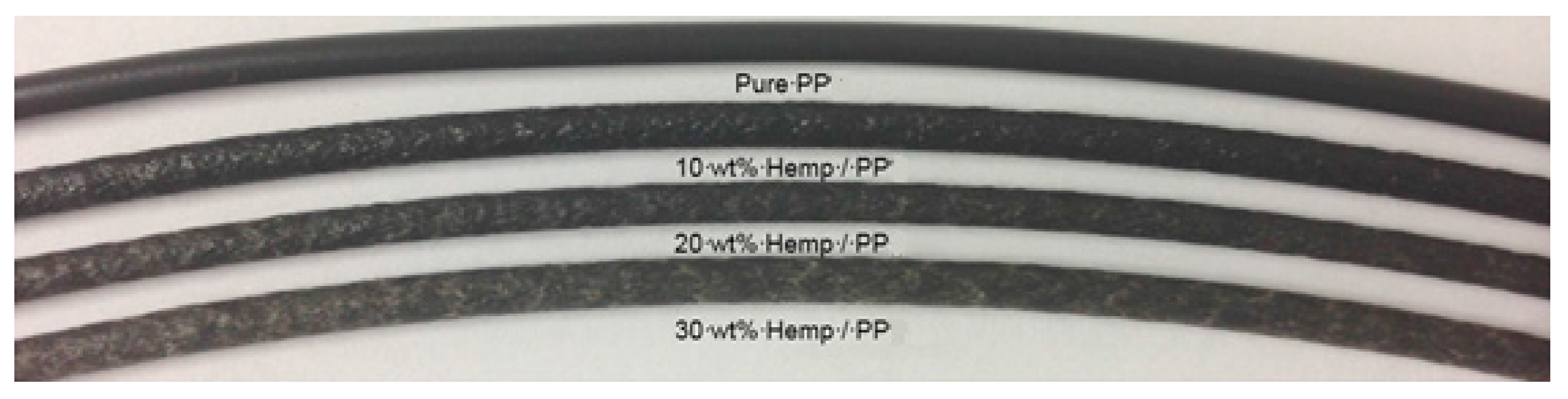
Once the composite material had solidified at room temperature, it was granulated using an 8 mm sieve. The resulting composite granules were placed in an oven, and dried at 72 °C for 48 h. Re-extrusion was conducted as after the first extrusion cycle, clusters of fibers were visible. This was much improved by a second extrusion cycle. For the re-extrusion of the composite materials, a larger Lab Tech Scientific Twin Screw Extruder Type LTE20-44, with a medium-length 3 mm capillary was used with a temperature profile of 174 °C, 166 °C, 168 °C, 179 °C, and 188 °C along the barrel, a consistent composite feed rate of 14 RPM, screw speed of 30 RPM and torque of 52%. All seven composite variations were successfully extruded through the 3 mm diameter capillary (
Figure 3). The diameter of the filament produced varied for non-reinforced PP from 2.4 to 2.55 (standard deviation of 0.05) mm, and for reinforced filament showing no trend with fiber content from 2.6 to 3.1 (standard deviation varying from 0.08 to 0.23) mm.
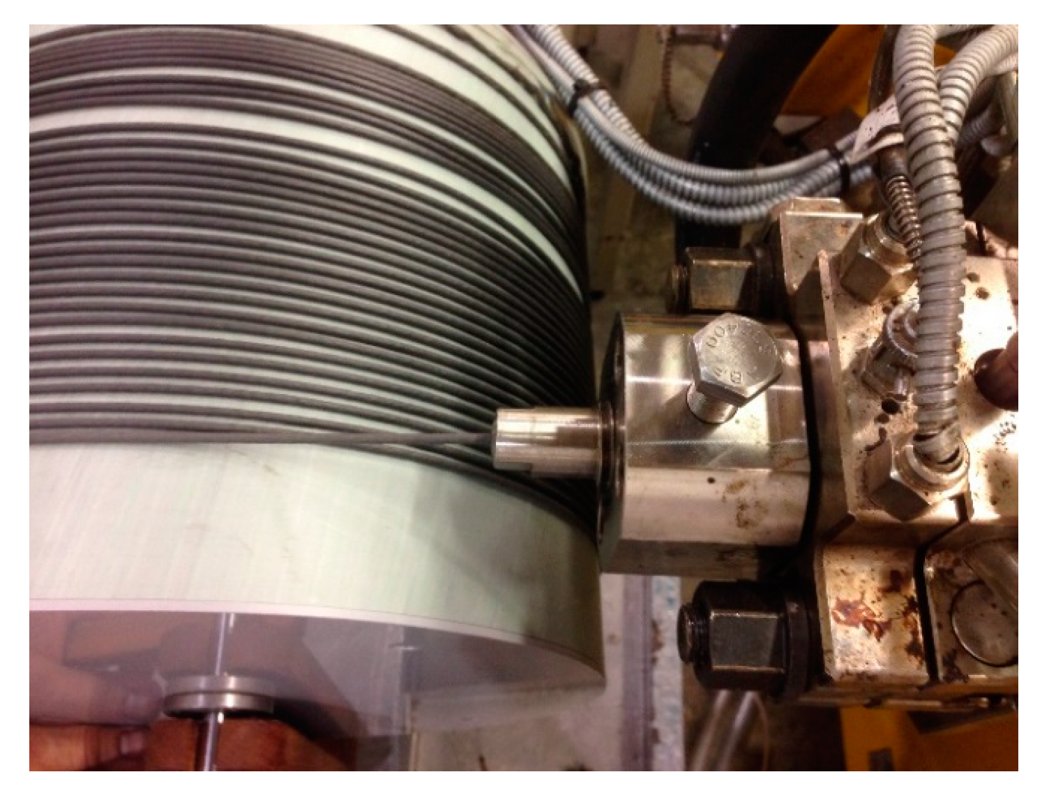
Due to a phenomenon known as die swell, the extrudate possessed an irregularly expanded cross sectional profile. To achieve a consistent geometric cross section, an electric spooling machine was purposely built for this investigation. By altering the distance and rotational speed of the drum, the rate of spooling could be synchronized with the rate of extrusion (
Figure 4). The optimization of these parameters ensured the precision of the extruded filament was within ±0.3 mm. The relatively gentle coiling process allowed sufficient time for the filament to solidify and retain the intended geometrical profile.
2.5. Fused Deposition Modelling of Tensile Testing Specimens
Prior to printing, all extruded filament was contained in sealed bags at ambient temperature. A 2014 Diamond Age 3D printer, which characterizes a typical household consumer style 3D printer, was to be used to produce dog bone specimens for tensile testing. Printing was carried out in a standard laboratory without temperature or humidity control. A 1 mm nozzle was used giving a layer thickness of approximately 1 mm. A 5 mm sheet of polypropylene was used as a print bed at room temperature. In-fill geometry was based on the use of concentric shapes following the outline of the sample. Initial efforts to manufacture test specimens revealed issues with die swell for both pure polypropylene and 10 wt % natural fiber specimens, similar to the elastic behavior that was displayed during filament extrusion. Therefore, to achieve 3D printed dog bones that allow for qualitative characterization, the printer settings had to be re-calibrated for each composite filament. This was accomplished by reducing the printing speed, along with reducing the feedstock diameter by approximately 80% through the printing software prior to printing.
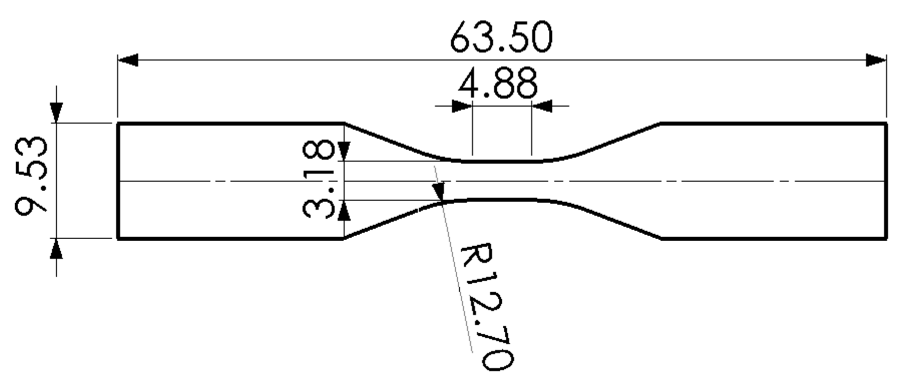
Filament wastage was reduced by printing small rectangular samples measuring 10 mm × 40 mm × 3 mm to ensure the printer was correctly calibrated prior to the production of dog bone samples. The design of the dog bone tensile test specimens were geometrically compliant to the ASTM D638-10 standard, which details the testing method for the tensile properties of plastics. Specifically, a Type V specimen (micro-tensile) profile was adopted (see
Figure 5) to ensure that quantity of available filament was sufficient for multiple dog bone and filament tensile tests. The thickness of the test-pieces was made up of three layers giving an approximate thickness of 3 mm.
Another identified issue was the warping of dog bone specimens during fused deposition modelling. This was attributed to the heated-glass build platform of the 3D printer, which facilitated different cooling rates between initial and subsequent layers, leading to variations in both internal stresses and shrinkage. Literature revealed that heated-glass build platforms are specifically optimized for polylactic acid (PLA) and acrylonitrile butadiene styrene (ABS) filaments but not PP. A 6 mm thick sheet of low density polyethylene (LDPE) was adopted for composite filaments in this investigation, allowing the extruded molten filament to fuse and solidify almost instantaneously.
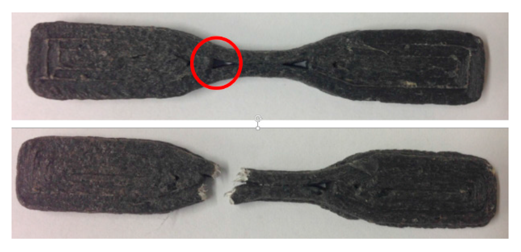
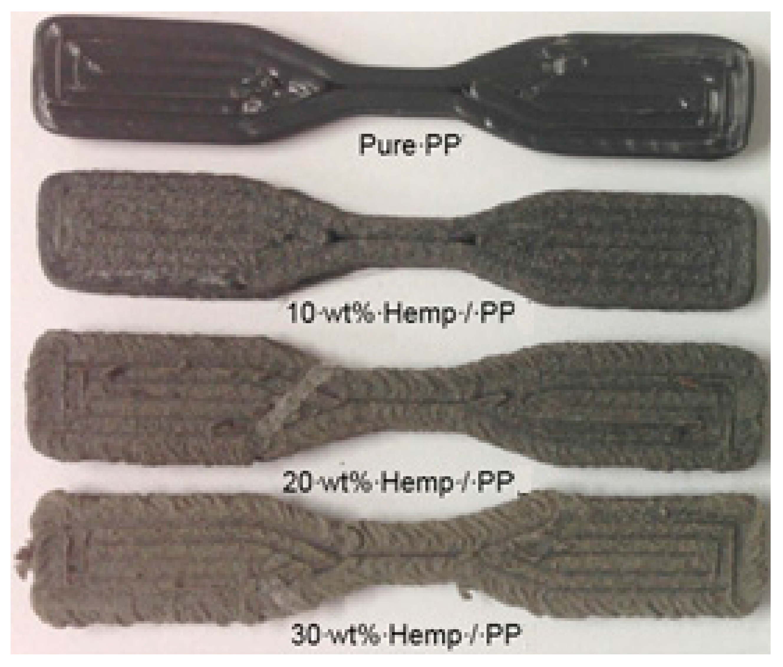
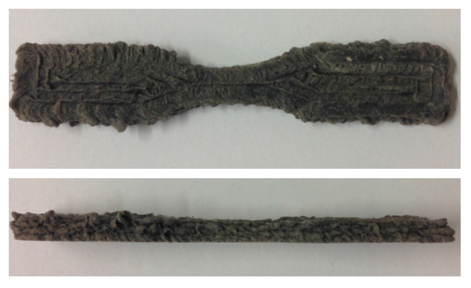
Ultimately, five dog bone samples of each filament specimen were manufactured (see
Figure 6). As a control, five dog bone samples were also produced using pure recycled polypropylene. All 35 dog bone specimens were printed using a concentric fill pattern with a 1.5 mm extrusion nozzle. The temperatures of the nozzle and the build platform were maintained at 230 °C and ambient temperature respectively. All of the tensile test samples were printed in a 24 h period, and were stored in sealed bags for 48 h prior to mechanical testing.
2.6. Mechanical Testing
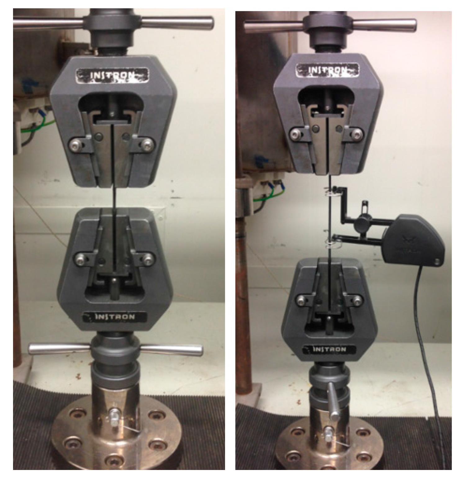
Tensile testing was performed according to ASTM D638: Standard Test Method for Tensile Properties of Plastics. The ultimate tensile strength and Young’s modulus of the dog bone and filament specimens was determined using an Instron 33R4204 universal testing machine equipped with a 5 kN load cell. A standard cross-head speed of 1 mm/min was applied to both dog bone and filament specimens (
Figure 7).
Strain of filaments was measured using an Instron 2630-112 extensometer at the at the centre of a 50 mm gauge length at the Univeristy of Waikato, Hamilton, New Zealand. All composite specimens were tested until failure, whereas unfilled polypropylene specimens were only tested to a point of maximum stress due to excessive necking.
2.7. Scanning Electron Microscopy
SEM micrographs of dog bone and filament fracture surfaces were obtained using a Hitachi S-4100 field emission scanning electron microscope (SEM) at the University of Waikato, Hamilton, New Zealand. Prior to observation, the samples were mounted on aluminum stubs using carbon tape, and the transverse corners of each sample was coated with carbon paint to provide a conductive path. A Hitachi E-1030 ion sputterer (University of Waikato, Hamilton, New Zealand) was used to coat the samples with a plasma sputtering (consisting of platinum and palladium), in order to prevent them from becoming charged under the electron beam.
3. Results and Discussion
3.1. Surface Finish of FDM Composite Specimens
According to literature, the surface finish of fiber reinforced polymer composites becomes progressively more abrasive and dull with increasing fiber content [
11,
12]. This relationship was largely observed in harakeke, and to a lesser degree in hemp composites during this investigation. All 10 wt % natural fiber dog bone specimens maintained identical geometrical accuracy to the unfilled polypropylene specimens, albeit with a lower gloss texture. A small proportion of the 20 wt % samples, along with most of the 30 wt % samples, possessed an irregular surface finish with a ribbon like texture, as shown in
Figure 8.
The cause of the irregular surface finish was attributed to intermittent blockages in the 1.5 mm extrusion nozzle leading to a decrease in dimensional accuracy and which could also have potentially influenced the layer adhesion quality of the specimens. Using a smaller 1 mm extrusion nozzle resulted in increased obstruction, leading to noticeable gaps in test specimens. However, increasing the diameter of the extrusion nozzle to 2 mm virtually eliminated this effect, at the expense of inferior build resolution for the test specimens. Increasing the diameter of the print nozzle to 2 mm decreased the surface roughness, but the round shape of the extruded material is more pronounced when looking at a part printed using a larger nozzle (stack of 2 mm cylinders compared to 1 mm cylinders), thus reducing the resolution control.
3.2. Mechanical Properties
Good quality fabrication of FDM components is dependent on the quality of the feedstock filament. The mechanical properties of natural fiber-reinforced filament are heavily influenced by parameters such as fiber length, alignment, dispersion and interfacial bonding [
13,
14].
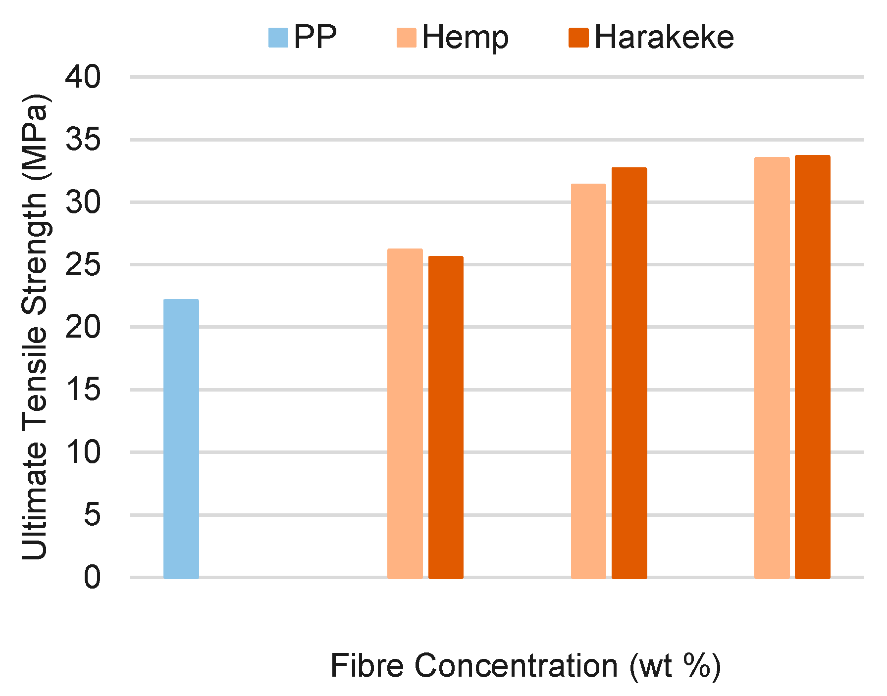
Figure 9 demonstrates the influence of gradually increasing the fiber content on the tensile strength of polypropylene filament; increased fiber content was found to result in increased ultimate tensile strengths. Hemp and harakeke reinforced filaments at 30 wt % both gave tensile strengths of 34 MPa, an increase of over 51% when compared with the 22 MPa ultimate tensile strength of unfilled polypropylene.
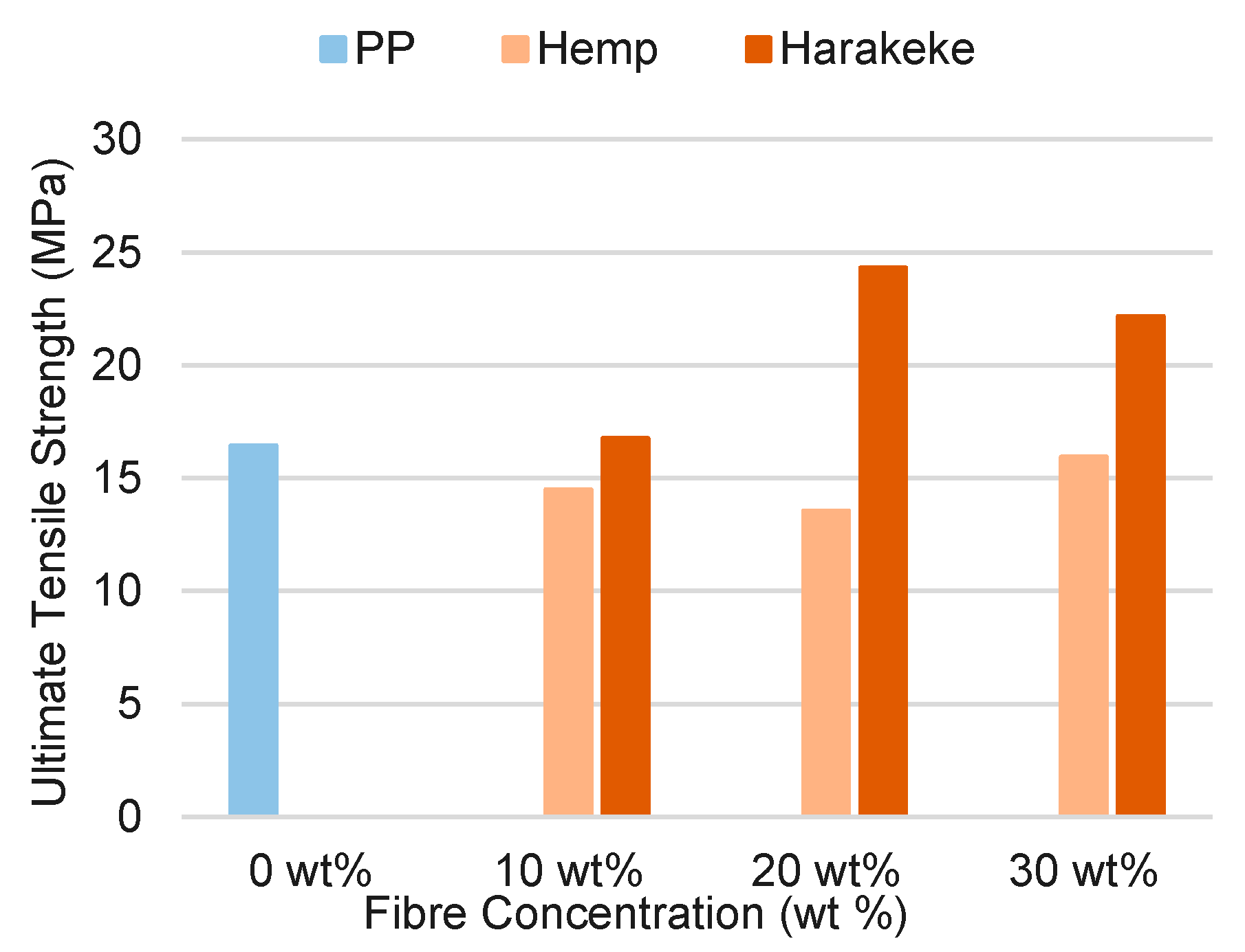
The influence of fiber reinforcement on tensile strength of printed dog-bone samples was found to be more variable than for filament (see
Figure 10). Much better strength was obtained with harakeke fiber than for hemp; the largest increase in tensile properties was for the 20 wt % harakeke reinforced dog bone specimens with an ultimate tensile strength almost 49% higher than unfilled polypropylene. However, a drop in tensile strength with reinforcement was observed for the hemp reinforced dog bone specimens; the 20 wt % hemp dog bone possessed a tensile strength of approximately 14 MPa, making it almost 18% weaker than the unfilled polypropylene specimen. Such reduction for hemp, in contrast to that for harakeke fiber along with the higher strengths for filaments, suggests that issues relating to poor interlayer fusion, and the presence of stress concentration points occurring during FDM could have a greater affect on the hemp printed specimens [
15]. Better values obtained with harakeke fiber could be explained by it being a finer fiber (approximately half the diameter of the hemp fiber) and thus able to flow more readily through the fine nozzle used in FDM. Better flow could indeed lead to better fusion between strands and layers. Overall reduction of strength between filament and printed samples supports the need to further optimize print quality in order to produce better properties.
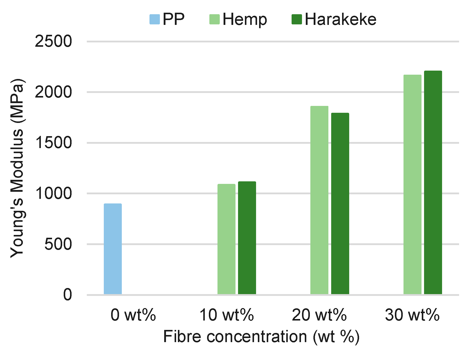
The increase in fiber content consistently improved the stiffness of filaments, as observed in
Figure 11.
The increased stiffness for both hemp and harakeke composites were similar. The 30 wt % hemp and harakeke filament possessed a Young’s modulus of 2163 MPa and 2202 MPa, respectively, constituting an increase of over 143% when compared with the unfilled polypropylene. Since the unfilled polypropylene filament encountered comparatively more die swell than composite filaments during extrusion, the observed increase in Young’s modulus can be attributed to both reduction of chain mobility brought about by higher fiber concentration, and the stiffness of the reinforcing fibers themselves.
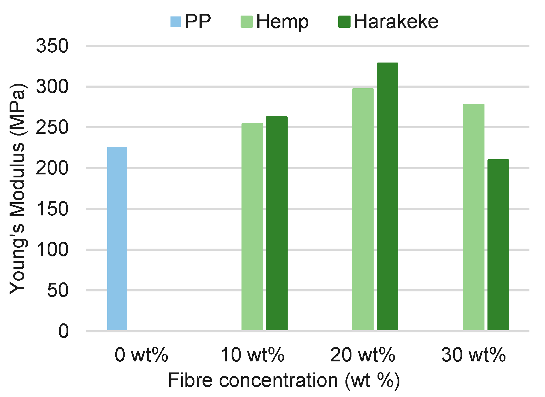
Overall, the Young’s modulus of FDM printed samples (see
Figure 12) was lower than for filament, although stiffness increased with fiber content except at 30 wt % fiber where reduction occurred. Hemp specimens experienced a 6.5% drop in Young’s modulus when the fiber concentration was increased from 20 to 30 wt %, whilst harakeke encountered a decrease of almost 36%.
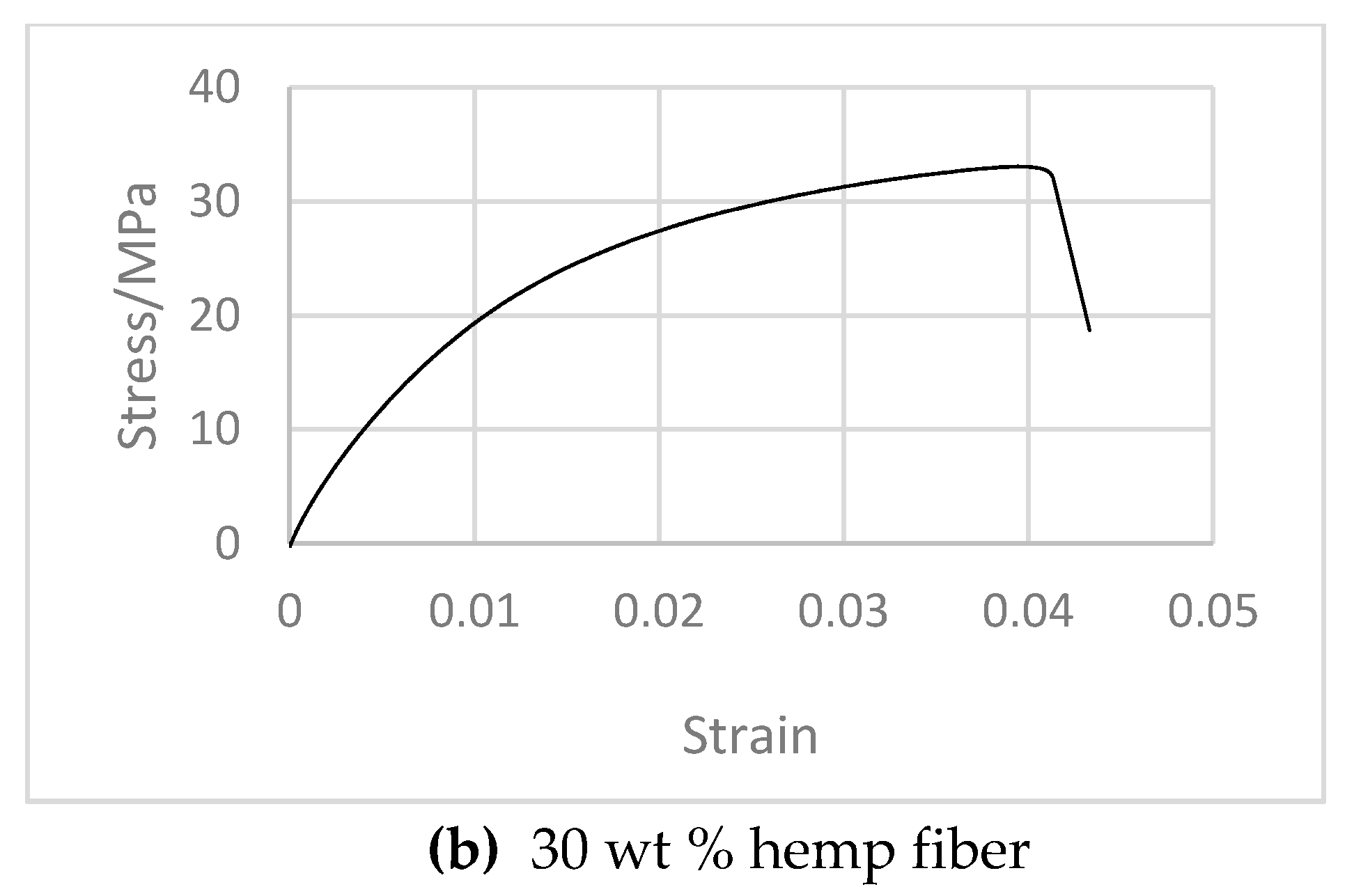
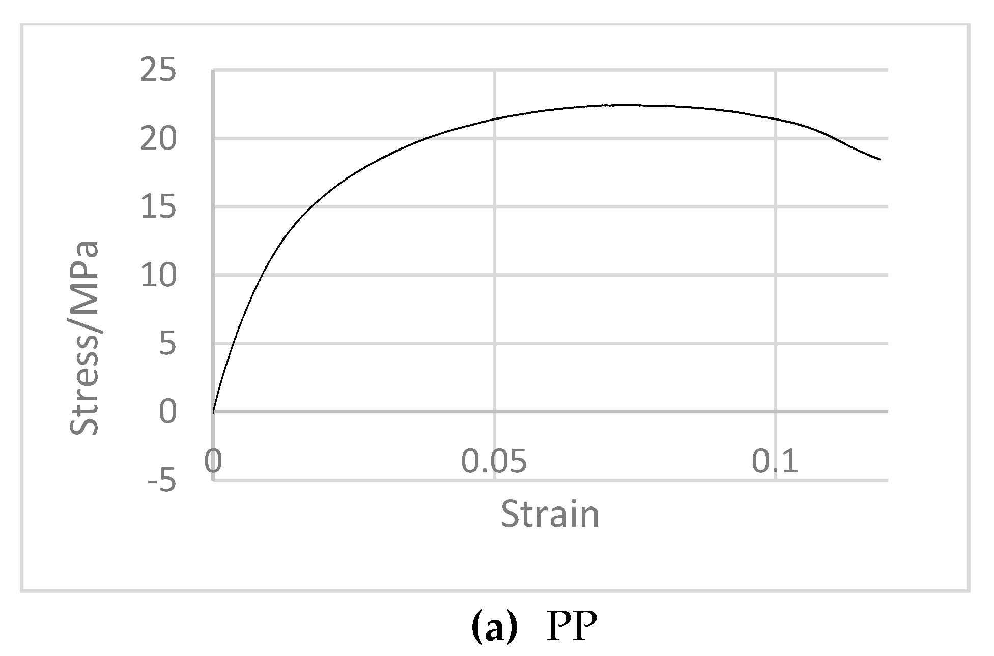
Filament and dog bone samples demonstrated a clear transition from ductile to brittle failure mode, starting at both 10 wt % hemp and harakeke with failure strain generally reducing with increasing fiber content and similar behavior for both hemp and harakeke fiber (see
Table 1) . Typical stress versus strain graphs are shown in
Figure 13.
3.3. Analysis of SEM Micrographs
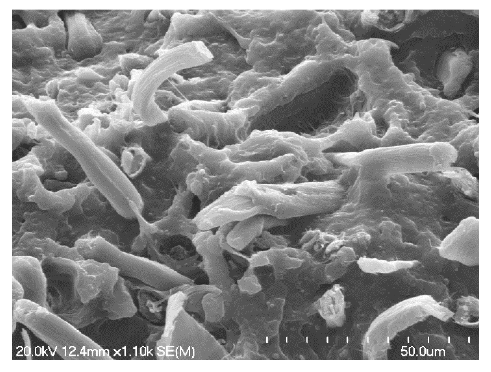
Prominent surface features of fractured dog bone samples and filament are displayed in the micrographs of
Figure 14 and
Figure 15 for harakeke fiber reinforcement. The fracture surface of the 20 wt % harakeke filament provides evidence of uniform fiber dispersion, fiber pull-out, and a certain degree of fiber alignment; exposed fibers and holes from which they have been extracted can be seen. There is far less evidence of fiber fracture, suggesting poor adhesion between the fibers and the matrix [
16].
Although fiber fracture was observed (see
Figure 14), a larger proportion of fibers appear to have experienced pull-out.
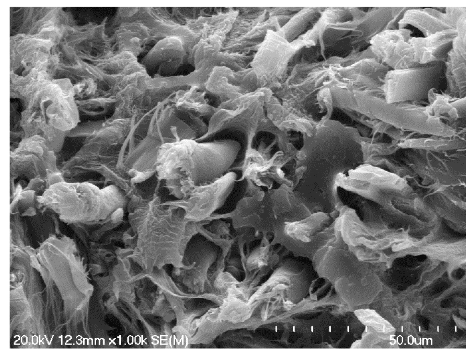
The increased thickness of individual hemp fibers was apparent on fracture surfaces (see
Figure 16). Fiber pull-out also appeared to be prevalent, however, in contrast to the harakeke filament, there was a significant amount of plastic deformation of the matrix surrounding the fibers, suggesting more resistance to fiber pull-out [
16]. Some protruding hemp fibers could also be seen to be coated by polypropylene, suggesting that fiber wetting for hemp filament was comparatively better than harakeke.
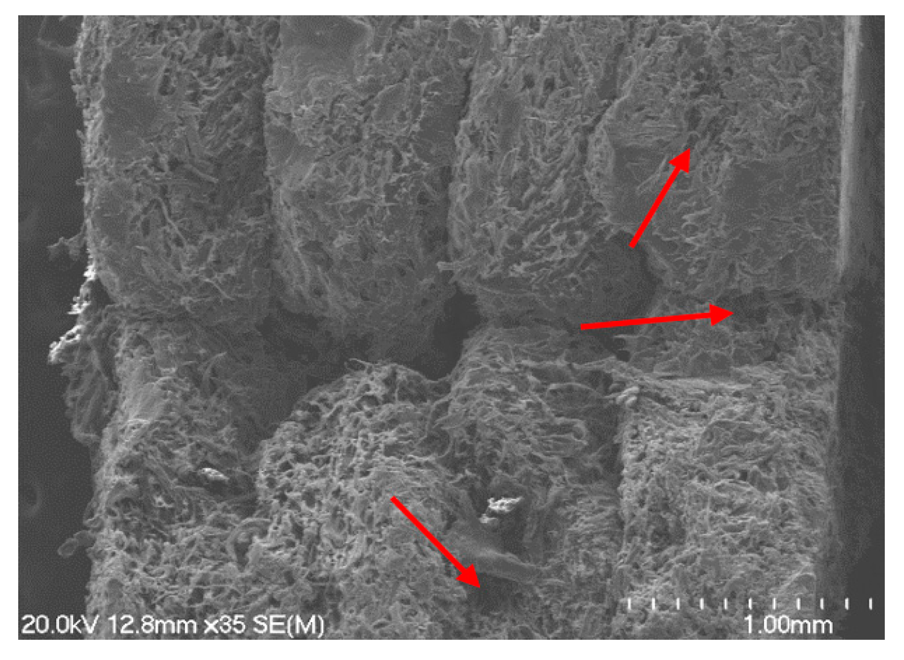
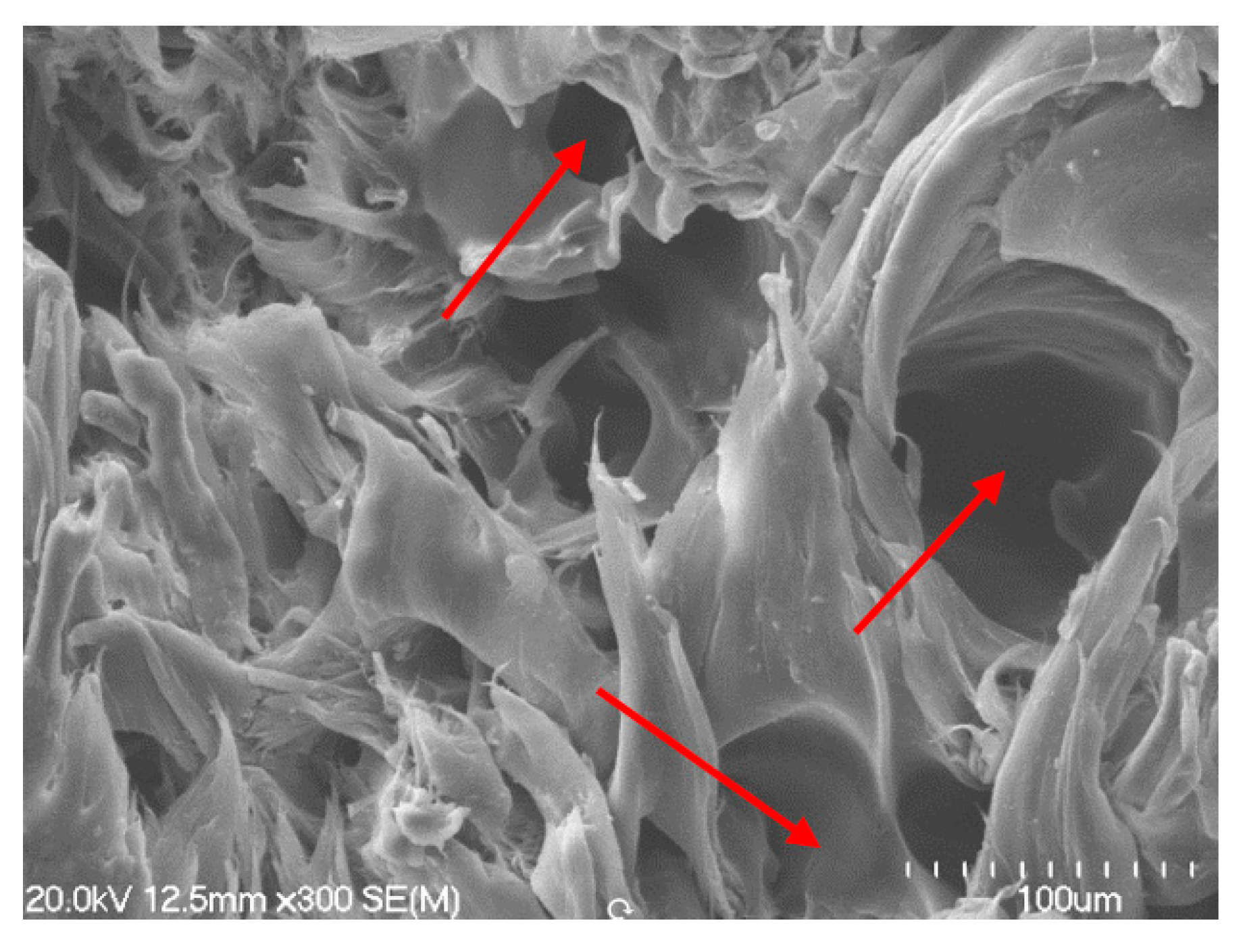
The fracture surface topography of the FDM dog bones differed slightly when compared with the filament, as seen in
Figure 17 and
Figure 18. There was notably more porosity, especially in the hemp composites, which would have contributed to the relatively low failure strength and stiffness of hemp dog bones during tensile testing.
The increased porosity of the hemp dog bone samples compared to filament samples is attributed to the FDM processing stage. Many of these voids exceed the 15–50 micron diameter of individual hemp fibers, suggesting that they are not a consequence of fiber pull-out. These voids would have behaved as stress concentrators during tensile testing, which would likely have contributed to premature failure of the dog bone samples. This along with lower print quality due to lack of flow and gaps between layers could explain the vast disparity between hemp dog bones and filament of 20 wt % and 30 wt %, where there was a reduction of tensile properties of over 50%. These results highlight the importance of reducing the porosity of samples while printing. The porosity could potentially be reduced by drying the filament in an oven prior to FDM, eliminating any residual moisture and printing at controlled humidity.


