Article

Manufacturing Design and Analysis of Bending Technology by the Variation of the Initial Technological Parameters

1
Department of Mechanical Engineering, University of Debrecen, Ótemető str. 2-4, 4028 Debrecen, Hungary
2
Department of Basic Technical Studies, University of Debrecen, Ótemető str. 2-4, 4028 Debrecen, Hungary
*
Author to whom correspondence should be addressed.
J. Manuf. Mater. Process. 2025, 9(8), 272; https://doi.org/10.3390/jmmp9080272
Submission received: 18 June 2025 / Revised: 30 July 2025 / Accepted: 5 August 2025 / Published: 11 August 2025

Abstract

The aim of this study is a detailed methodological analysis of the bending technology based on literature sources and the analysis of the correlation between the technological parameters. During this research the process of the determination of the technological parameters and their practical interpretation is given special attention. We analyze the technological process in a clear and understandable way using our own prepared figures to assist industrial and educational usage. This work contributes to a deeper understanding of bending technology and supports the basis of the technological decision. Furthermore four experiments will be conducted to find a correlation between the actual variable technological parameter (more variables will be selected) and the received technological parameters to analyze the function between these influential factors. This study can help industrial engineers and university students to understand the complexity of this technology, design all of the technological parameters that are needed to execute this technology for the manufacturing process, and enhance the quality of this metal forming process.

1. Introduction

The bending technology is a metal forming process where the parts of the workpiece are formed into an angular position relative to each other with plastic deformation (Figure 1). Cold bending technology is analyzed where the temperature is not changed during the metal forming process [1,2].
In recent years, the field of tube and profile bending has undergone remarkable advancements, driven primarily by the growing industrial demand for components that are not only lightweight and strong but also capable of assuming increasingly complex geometries. These requirements are particularly pronounced in high-performance sectors such as the automotive, aerospace, and healthcare industries, where structural efficiency, weight reduction, and high precision are essential. Consequently, researchers have focused on developing new bending methods and refining existing technologies to meet these rigorous standards. The outcome has been a diverse body of research that contributes to the improved understanding and implementation of modern bending techniques, both in theory and in industrial practice.
One particularly noteworthy study [3] offers a broad overview of the importance of bent tube components in the aviation and aerospace industries. It addresses key technological challenges commonly encountered in the bending process—such as wrinkling, wall thinning, springback, and deformation—by reviewing recent advances in tube bending technology. The paper underscores the central role of bending in producing high-strength yet lightweight structures and provides valuable insight into ongoing trends and future directions in the field. Its contribution lies in the comprehensive analysis of the bending process and its application to modern, lightweight materials that require high forming accuracy.
A cluster of studies has delved deeply into the free-bending technique, which has gained attention as a flexible and relatively new approach to forming tubes and profiles. One investigation [4] explores the adoption of this technique in the automotive industry, highlighting its ability to achieve high bending speeds and accommodate flexible geometries while minimizing the need for physical prototyping through the use of finite element method (FEM) simulations. The resulting process is not only faster and more adaptable but also cost-effective. Building on this, another paper [5] demonstrates free bending’s capacity to create complex geometries suitable for car chassis and space frame applications. Through experimental validation and numerical analysis, the study showcases the method’s versatility and potential for broader industrial use. A more comprehensive evaluation of free-bending forming (FBF) is provided in [6], where the authors examine its application in producing thin-walled metallic tubes. This review covers fundamental principles, modeling strategies, and process limitations, while also addressing key challenges such as springback, cross-sectional distortion, and over-thinning. The paper also explores recent developments in multi-axis FBF systems, marking a significant step forward in process control and quality assurance.
The increasing need for more adaptable and precise forming techniques has also stimulated interest in flexible 3D bending methods. In [7], researchers investigate a flexible 3D stretch bending (FSB) process using multi-point dies (MPD), introducing a flexible fundamental unit (FFU) capable of adjusting to different geometries. This unit reduces springback error significantly and helps eliminate common surface defects such as wrinkles and cracks, improving overall part quality. Similarly, [8] introduces a novel 3D stretch bending device that offers two degrees of freedom and utilizes multi-point roller dies to simplify shape adjustment for large, complex components. The study’s numerical simulations and experiments demonstrate how adjusting roller die parameters improves forming accuracy and reduces surface defects like dimples.
Advancements in tool and die design also play a crucial role in improving bending operations. A forward-looking study [9] proposes hybrid tooling systems composed of metallic bases and polymeric die inserts. These hybrid tools offer a cost-effective and environmentally sustainable alternative to conventional rigid metal dies, especially in the context of mass customization and additive manufacturing. Manufactured through 3D printing and other rapid prototyping methods, polymeric inserts provide sufficient strength and wear resistance while allowing for quicker replacements and reduced tooling costs. The integration of such tools into bending processes represents a promising innovation in sustainable manufacturing.
The integration of bending with hydroforming techniques is explored in [10], where the authors simulate and compare two prebending approaches—rotary draw bending and die bending—as preparatory steps before hydroforming an automotive tie bar. The simulations focus on analyzing changes in cross-sectional shape and material thinning. These results are then used to simulate the subsequent hydroforming process, allowing for a more efficient and accurate assessment of manufacturing parameters.
Further refinements in die optimization are presented in [11], where three types of bending dies—sliding friction, roller, and ball—are evaluated within a 3D free-bending system. The study reveals that roller-type dies result in the lowest stress levels, reduced cross-sectional distortion, and more uniform wall thickness. This insight is particularly useful for selecting optimal die configurations in high-precision applications.
A more holistic view is provided in [12], which reviews recent technological innovations in industrial bending, particularly flexible stretch forming and 3D rotary stretch forming. The authors emphasize the importance of controlling dimensional variability, proposing analytical models that account for geometry, material properties, and process parameters. These models are essential for understanding the mechanisms behind local deformations and global springback, thereby enhancing the dimensional accuracy of the final components.
In [13], researchers propose a new bending method inspired by biomimicry, specifically snake-spine structures. This process, termed FSBRD-S (Flexible Stretch Bending with Roller Dies—Snake-like Mechanism), is capable of reducing crease defects during vertical bending operations with large angles. A finite element model is developed to study the effects of die contact modes on surface quality, and the results confirm that adjusting these contact modes improves the final geometry and appearance of the bent components.
The synergistic use of additive manufacturing and traditional forming techniques is examined in [14]. The paper investigates the adhesion strength of extrusion-based layers on selectively sintered surfaces, simulating hybrid manufacturing conditions. Using single-leg bending (SLB) tests, the study explores delamination behavior in combinations of hard and soft materials and evaluates how process parameters like nozzle temperature influence bonding performance. This hybrid approach opens new possibilities in customized and multi-material component production.
Medical applications are addressed in [15], where stepped bending is used to fabricate thin-walled, arc-shaped parts for small medical devices. The study focuses on the manufacturing of components for a prototype plasma sterilizer, highlighting the advantages and limitations of sequential V-bending. Although labor-intensive, this method allows for precise curvature and satisfies the strict quality standards typical of medical equipment.
In the field of composite and layered structures, study [16] investigates the forming of bimetallic pipes, which are essential in industries such as petrochemicals and automotive manufacturing. The research addresses defects such as wrinkling and interlayer separation, while proposing theoretical and simulation-based solutions. The authors also suggest the use of artificial intelligence and neural network systems to improve forming accuracy and efficiency, indicating a shift toward intelligent manufacturing.
Finally, Ref. [17] explores laser-based bending, an alternative thermo-mechanical process suitable for microelectronics, shipbuilding, and aerospace. The study examines the influence of key laser parameters—such as power, speed, and beam diameter—on mild steel sheets and introduces an artificial neural network (ANN) model to predict bending outcomes. The use of an ANN represents a growing trend in combining traditional forming techniques with data-driven predictive modeling.
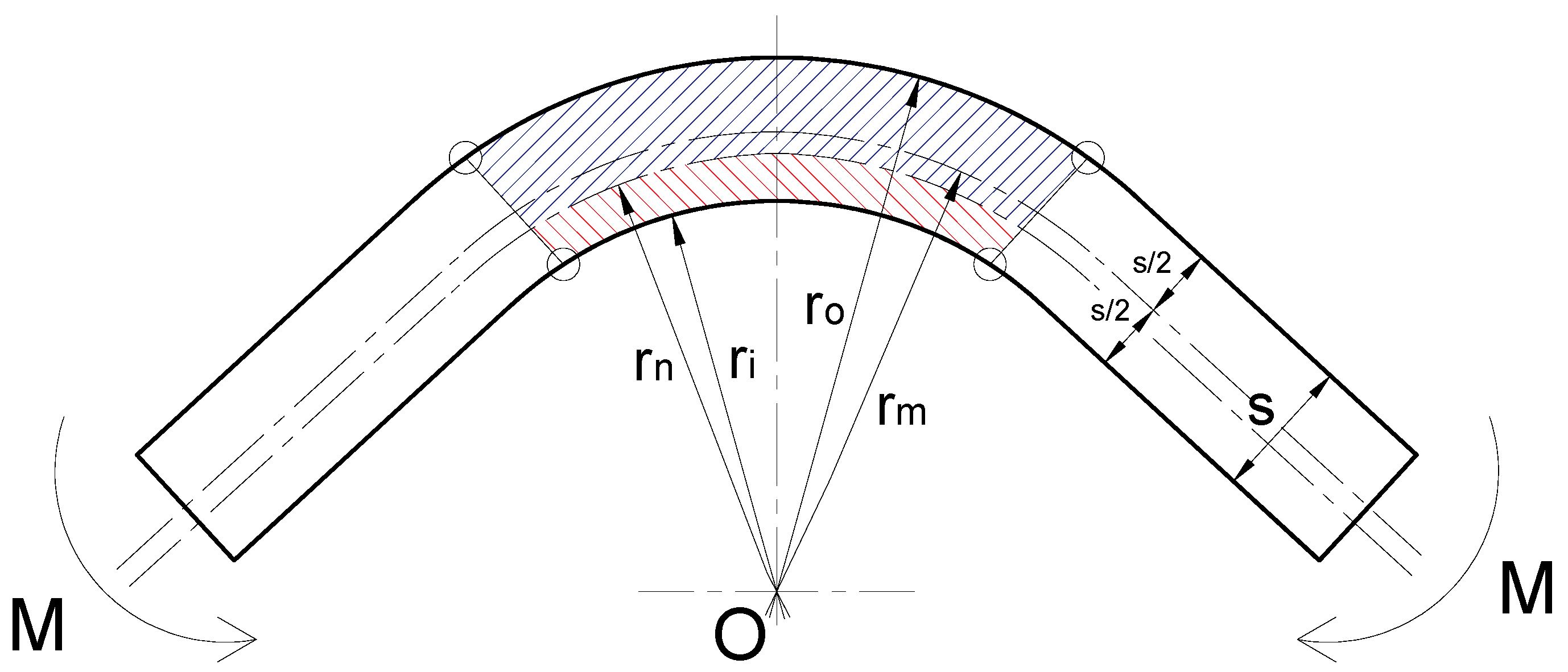
One of the most important parameters of the bending technology is the neutral radius (rn) which is the same as the middle radius (rm) so the thickness of the tension zone (blue hatched zone) is equal to the thickness of the compression zone (red hatched zone) in the case of elastic bending (Figure 2). After the cancellation of the M torque, the sheet can regain its original position [1,2].
In contrast the neutral radius and the middle radius are not equal, which is why the thickness of the tension zone is wider than the thickness of the compression zone in the case of plastic deformation (Figure 3). After the cancellation of the M torque, the sheet cannot regain its original position. It will be deformed [1,2].
The neutral radius belongs to the neutral strand whose length is permanent during the metal forming process; that is why the initial length of the workpiece has to be calculated according to the length of the neutral strand [1,2].
Naturally the used material is the same in both Figure 2 and Figure 3. The reason for the different hatching is to differentiate the tension zone and the compression zone during the metal forming process.
The formula of the middle radius is in both cases (Figure 2 and Figure 3)
r m = r i + r o 2
The formula of the neutral radius is
r n = r i + ξ · s 2
where
ξ = 1 in the case of elastic bending,
ξ > 1 in the case of plastic bending
This research can be interpreted as methodological [18,19], applied [20,21], and secondary [22,23] research that is primarily based on interpretation and synthesis of the available literature.

2. Materials and Methods

2.1. Determination of the Cover Length

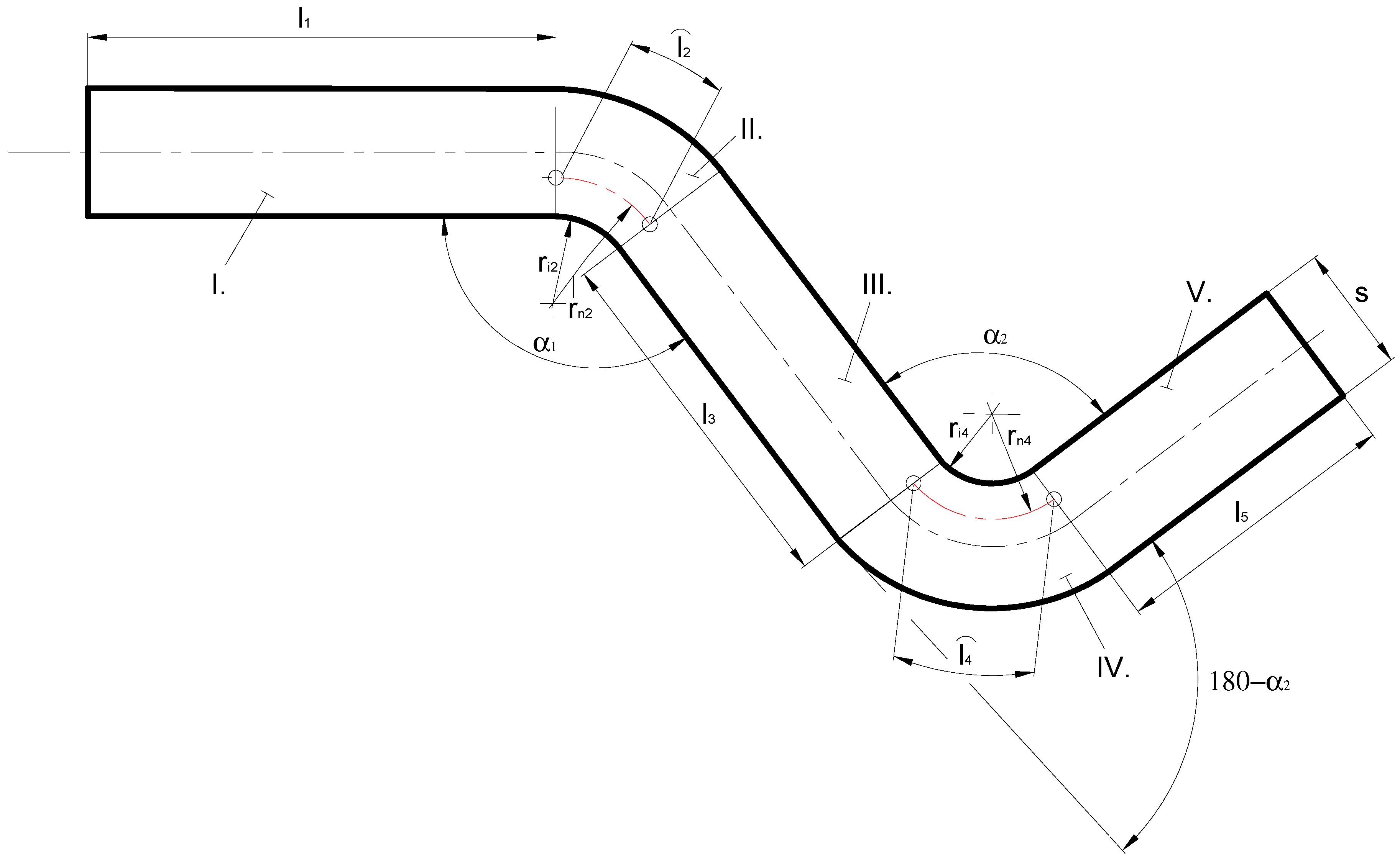
The cover length means a planar length for which the sheet or the spatial material has to be cut to get the required part shape (Figure 4) [1,2].
The workpiece has to be partitioned into different subparts to determine the manufacturing parameters. The lengths of the linear (I., III., and V.) sections are permanent during the metal forming process since bending technology does not happen on these subparts (Figure 4) [1,2].
Bending technology happens on the II. and IV. subparts where the neutral radiuses have to be determined first based on (2). Moreover, the length of the neutral strands has to be determined when we know the bending angles [1,2]:
l ^ = r n · α ^
The cover length can be determined based on the following formula, considering (2):
L = l + l ^ = j = 1 n l j + k = 1 m r i k + ξ · s 2 · α k ^

2.2. Springback Phenomenon

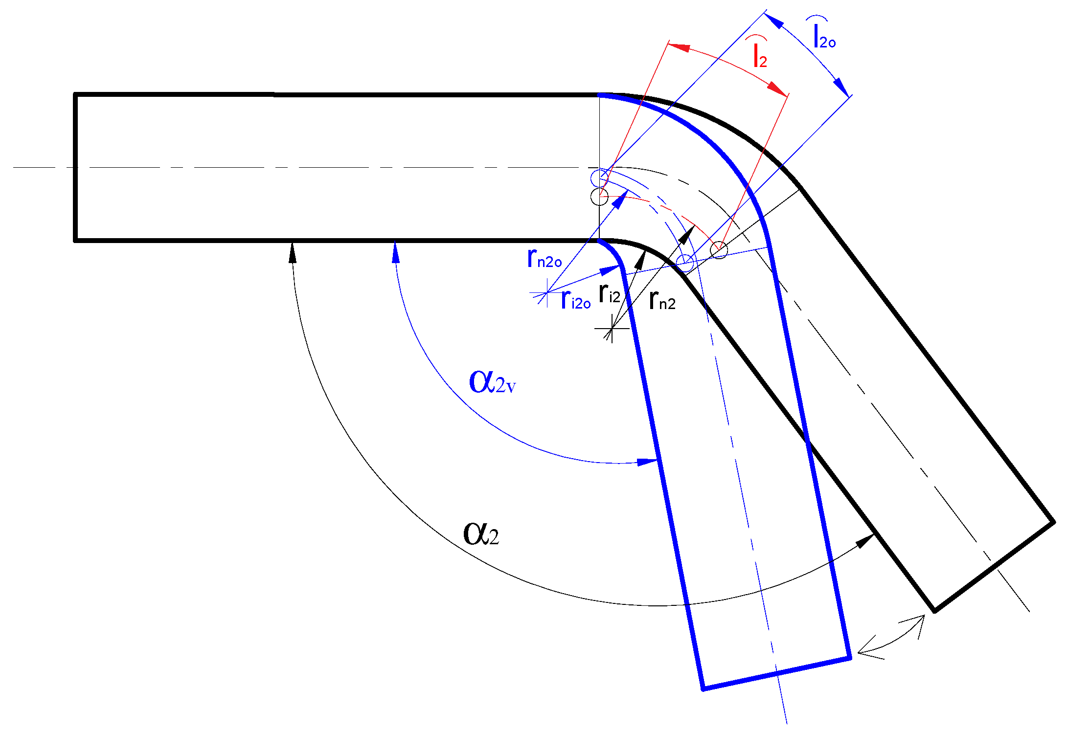
The material has to be overbended to provide enough space for the springback in the case of the given bending angle (α2) and inner radius (ri2) based on Figure 5. If the M torque is cancelled, the material has a bit of oscillation and then takes the prescribed bending angle (α2) and radius (ri2) (Figure 5) [1,2].
We start from the assumption that the neutral radiuses are equal in the case of normal bending and overbending [1,2]:
r i 2 + ξ 2 · s 2 · α 2 ^ = r i 2 v + ξ 2 · s 2 · α 2 v ^
Based on (5) the springback factor is
α 2 ^ α 2 v ^ = r i 2 v + ξ 2 · s 2 r i 2 + ξ 2 · s 2 = K
The value of the K factor is given by a standardized table. Based on this K factor, the modified bending angle (α2v) and the modified bending radius (ri2v) can be determined [1,2]:
α 2 v ^ = α 2 ^ K
r i 2 v = K · r i 2 + ξ 2 · s 2 ξ 2 · s 2

2.3. Determination of the Bending Force and Bending Torque

Liminality status: The entire workpiece is in a state of plastic deformation. Initial parameters: β, kf, b, s.
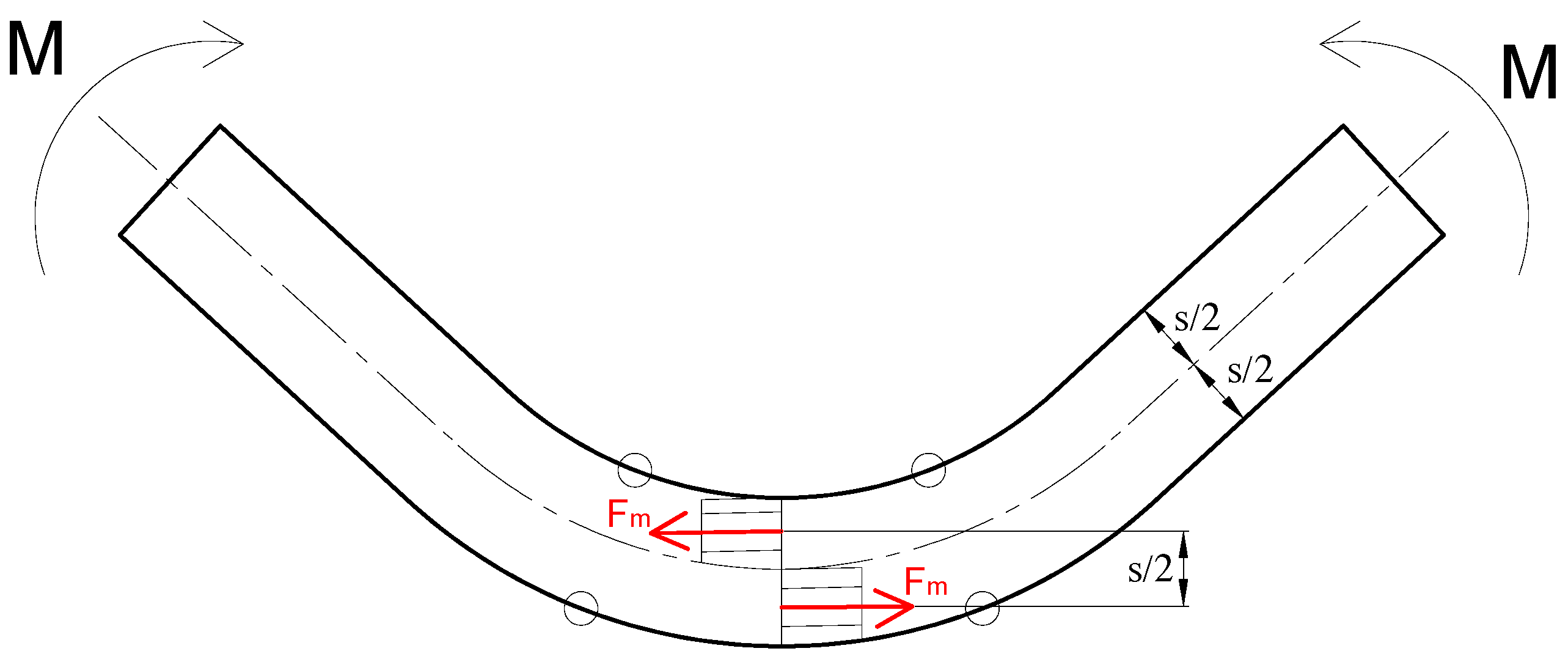
The internal force is present within the material in the case of bending technology (Figure 6) [1,2]:
F m = β · k f · b · s 2
The internal torque caused by the internal forces is [1,2]
M i = F m · s 2 = β · k f · b · s 2 4
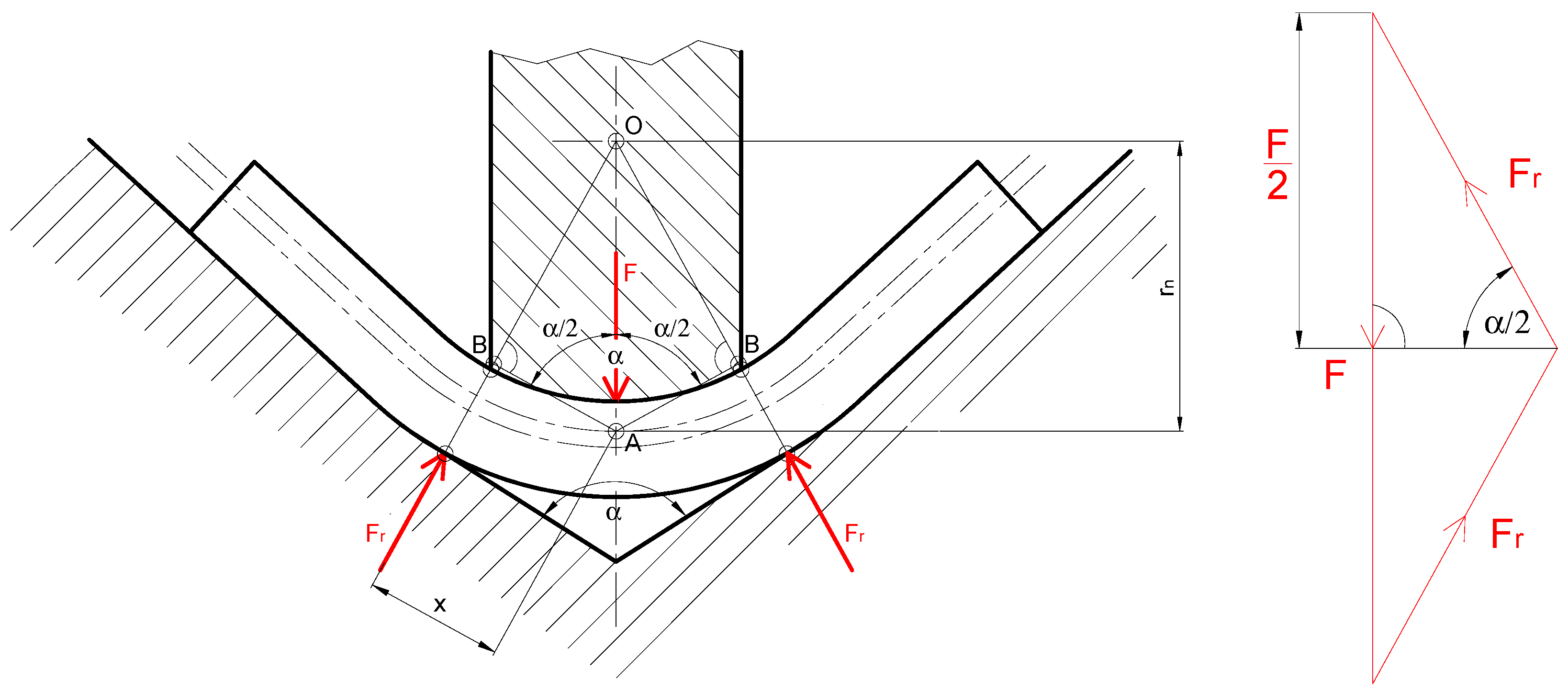
The bending technology can originate from the equilibrium of three forces. The external torque caused by the reaction force (Fr) is as follows (Figure 7) [1,2]:
M o = F r · x
where
x = r n · c o s α 2
F r = F 2 · s i n α 2
Substituting (12) and (13) into (11),
M o = F 2 · s i n α 2 · r n · c o s α 2
The internal torque and the external torque have to be equal [1,2]:
M i = M o
β · k f · b · s 2 4 = F 2 · s i n α 2 · r n · c o s α 2
Based on (16) the necessary bending force is
F = β · k f · b · s 2 2 · r n · t a n α 2

3. Results

Four experiments were executed to determine the effects of the variable technological parameter on the other parameters and analyze the shape of the charts between the variable and the analyzed technological parameter.
The initial experimental parameters were generated based on bending geometry experience. In the four experiments, a different initial geometric parameter is varied each time (bending radius, thickness of the bent sheet, bending angle, sheet width). Since no actual measurements were performed, there are no measurement errors in this case; however, the obtained results were determined with a precision of three decimal places and rounded in the mathematical sense.
The selected workpiece material is 42CrMo4. The flow stress is kf = 1000 MPa, and the β factor that characterizes the velocity of the stress increasing during the forming is β = 0.4.

3.1. Experiment I

The variable is the inner bending radius (ri).
Using the aforementioned technological formulas, the technological parameters are determined in Table 1 as a function of the changing inner bending radius. Six different inner bending radiuses were selected.
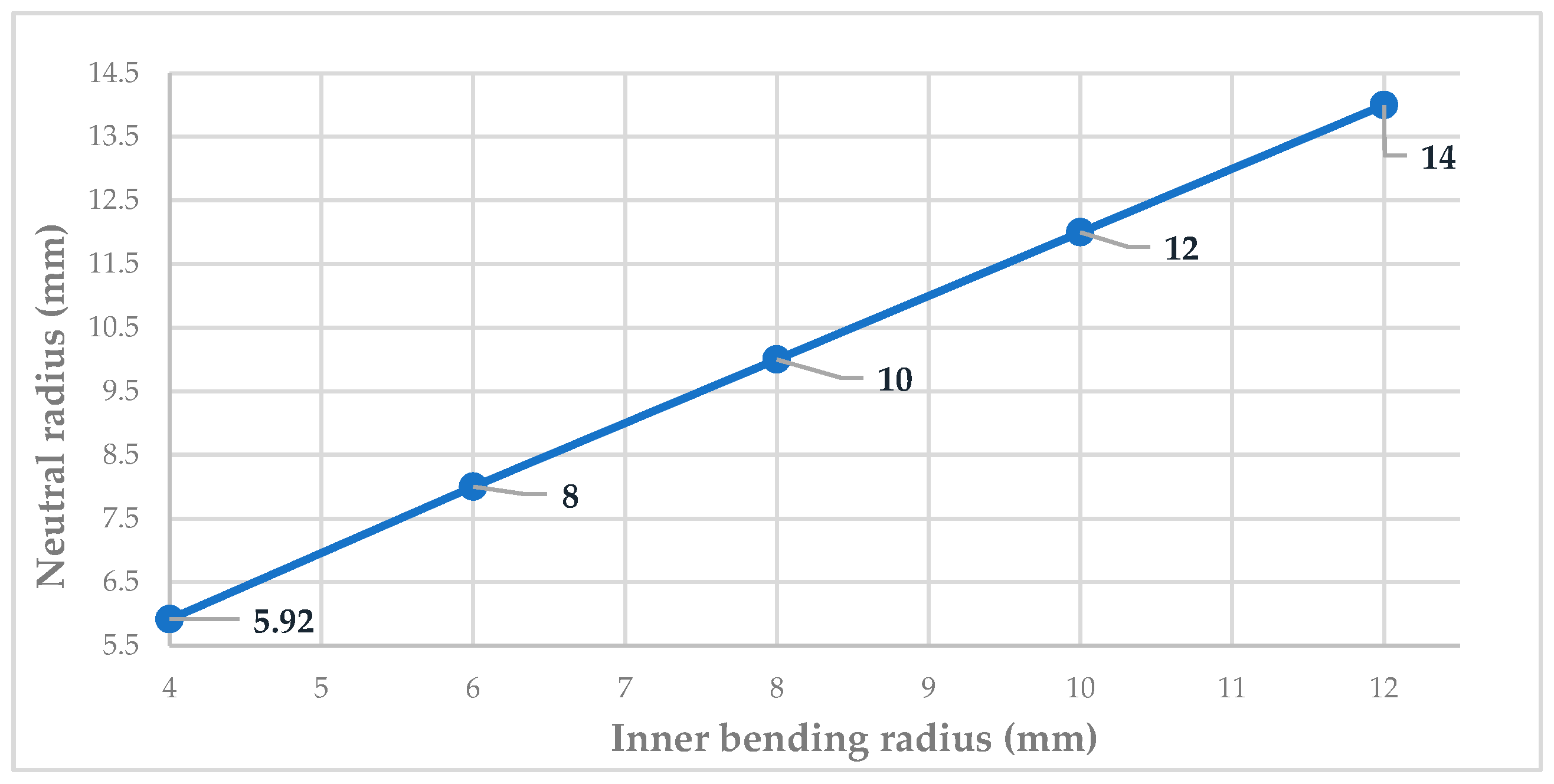
The larger the inner bending radius, the larger the neutral radius. The function between these parameters is linear (Figure 8). The shape of the function is the same in the case of the correlation between the inner bending radius and the modified bending radius (Figure 9).
The larger the inner bending radius, the lower the necessary bending force and the reaction force of the die (Figure 7 and Figure 10). The shape of the function is a hyperbola in both cases. The necessary bending force is always higher than the reaction force of the die.

3.2. Experiment II

The variable is the sheet thickness (s). The initial and the calculated parameters are in Table 2.
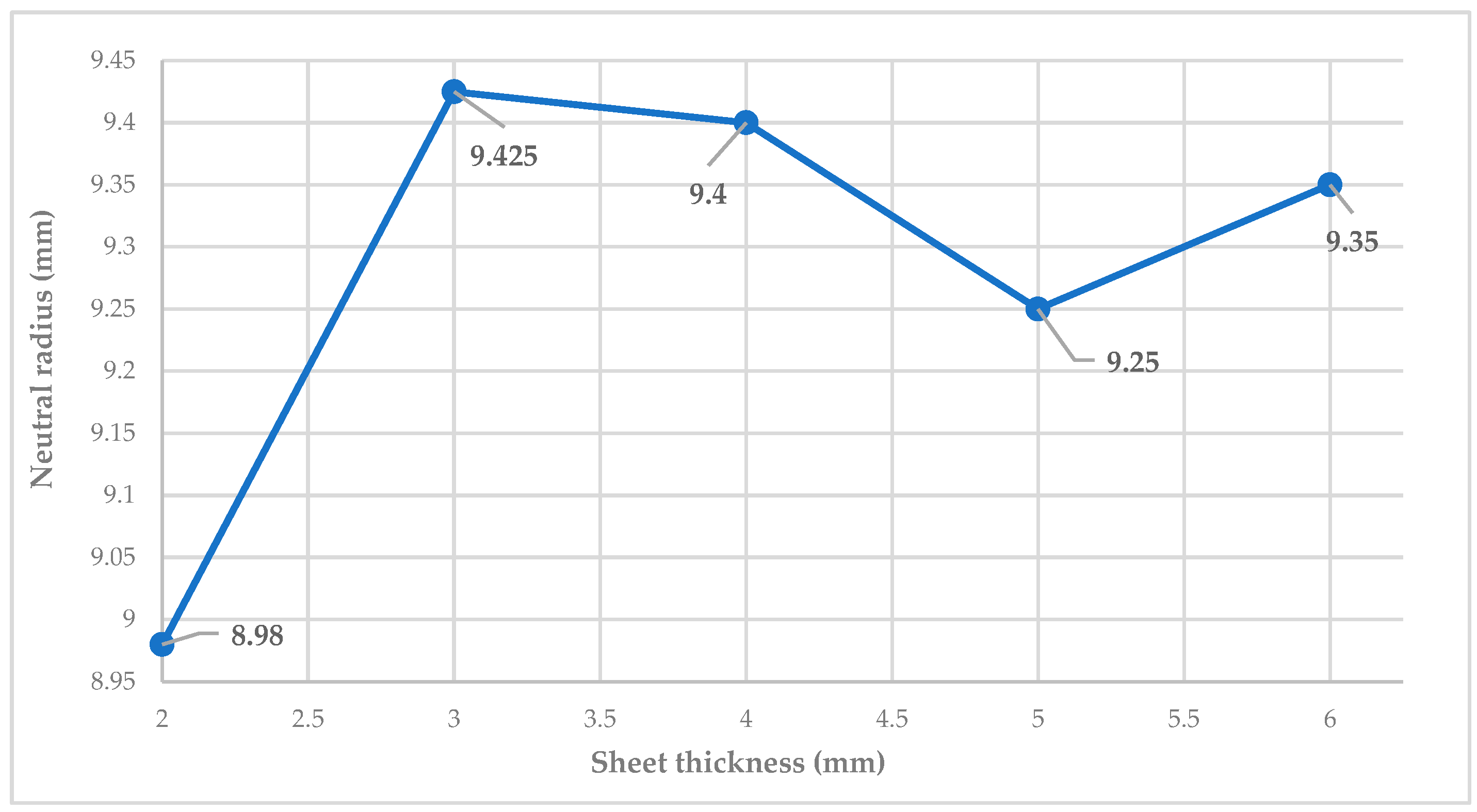
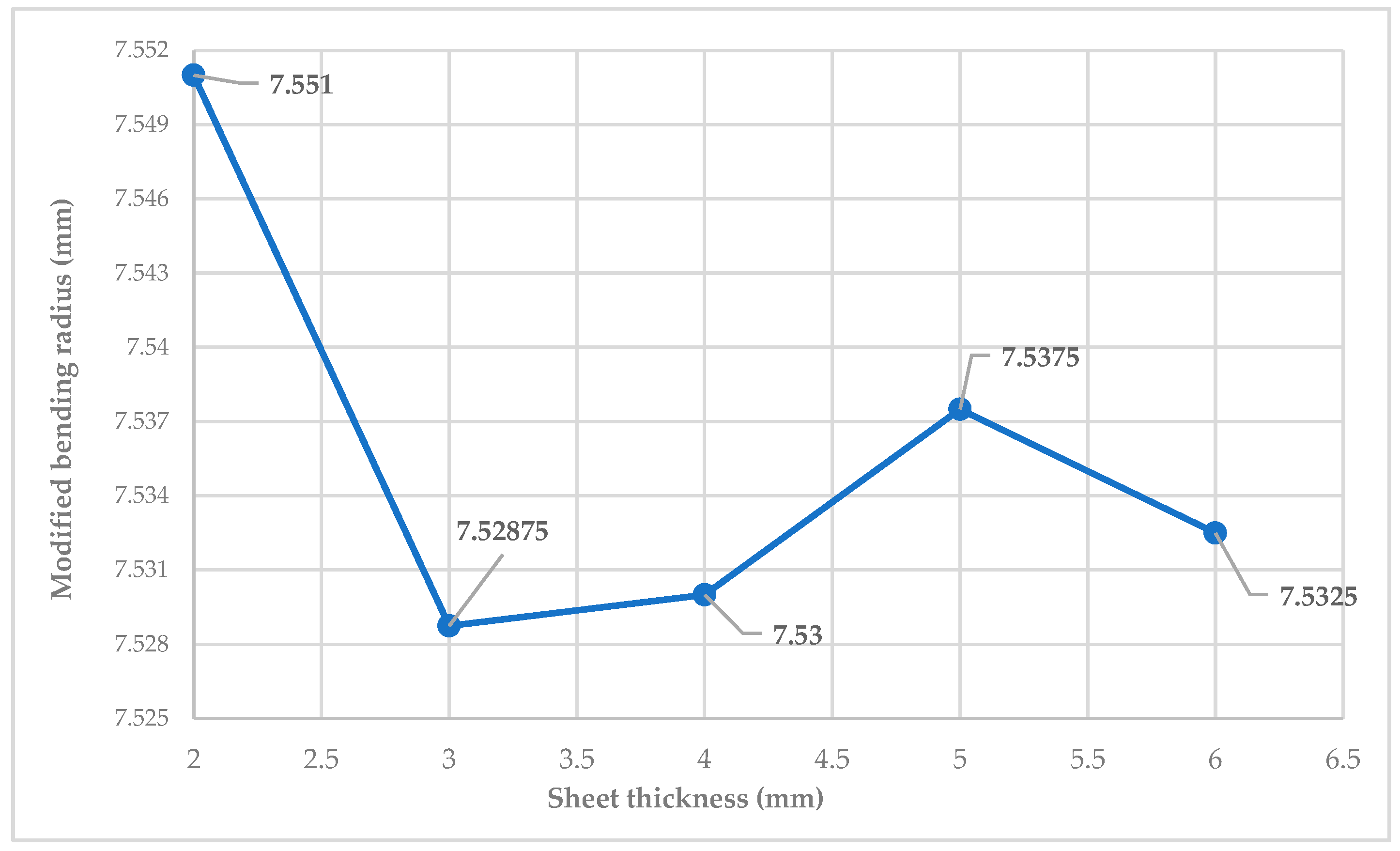
The neutral radius is fluctuating in the function of the changing of the sheet thickness (Figure 11). The same case can be considered between the function of the changing of the sheet thickness and the modified bending radius (Figure 12).
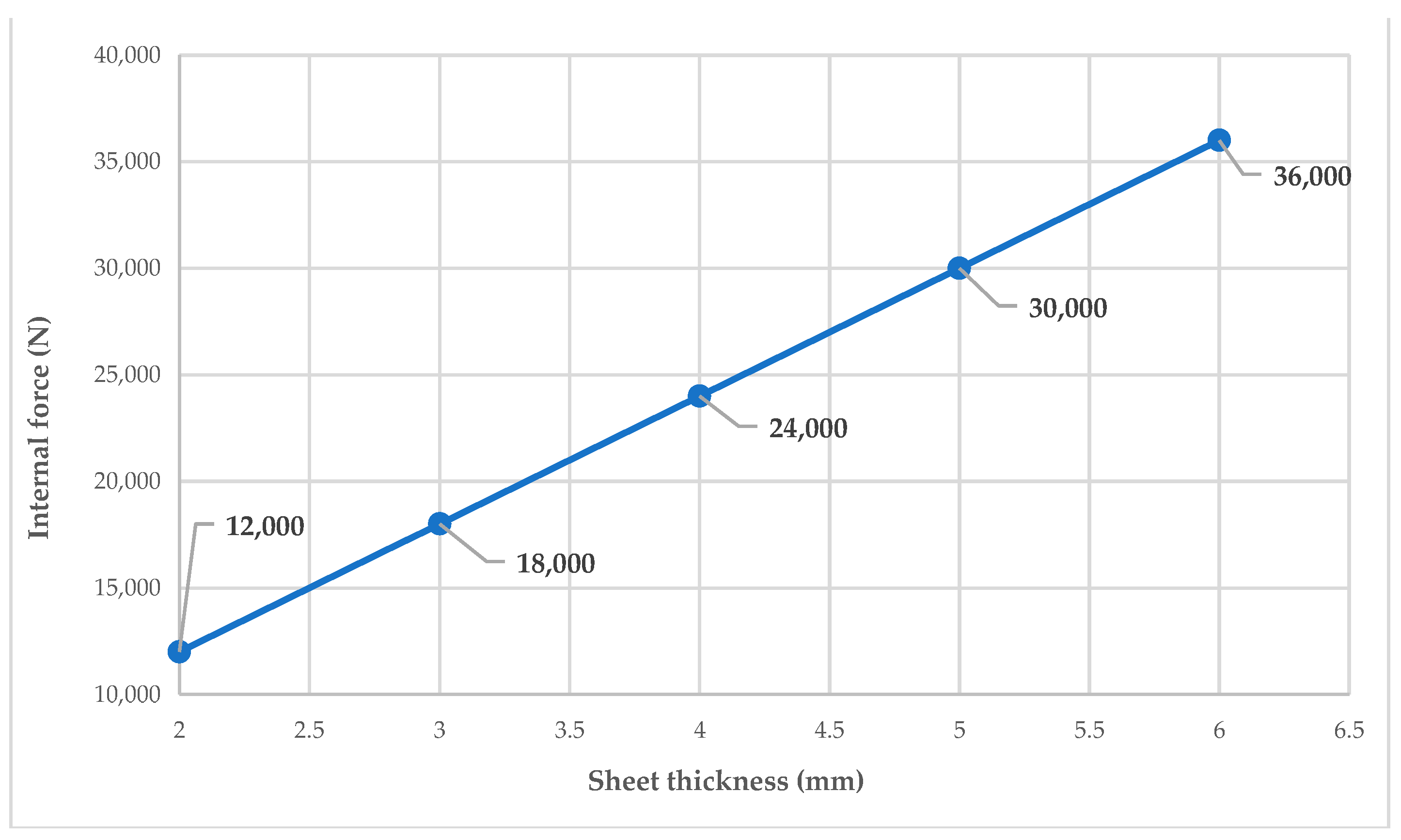
The shape of the function is linear between the changing of the sheet thickness and the internal force. The larger the sheet thickness, the larger the internal force of the same material (Figure 13).
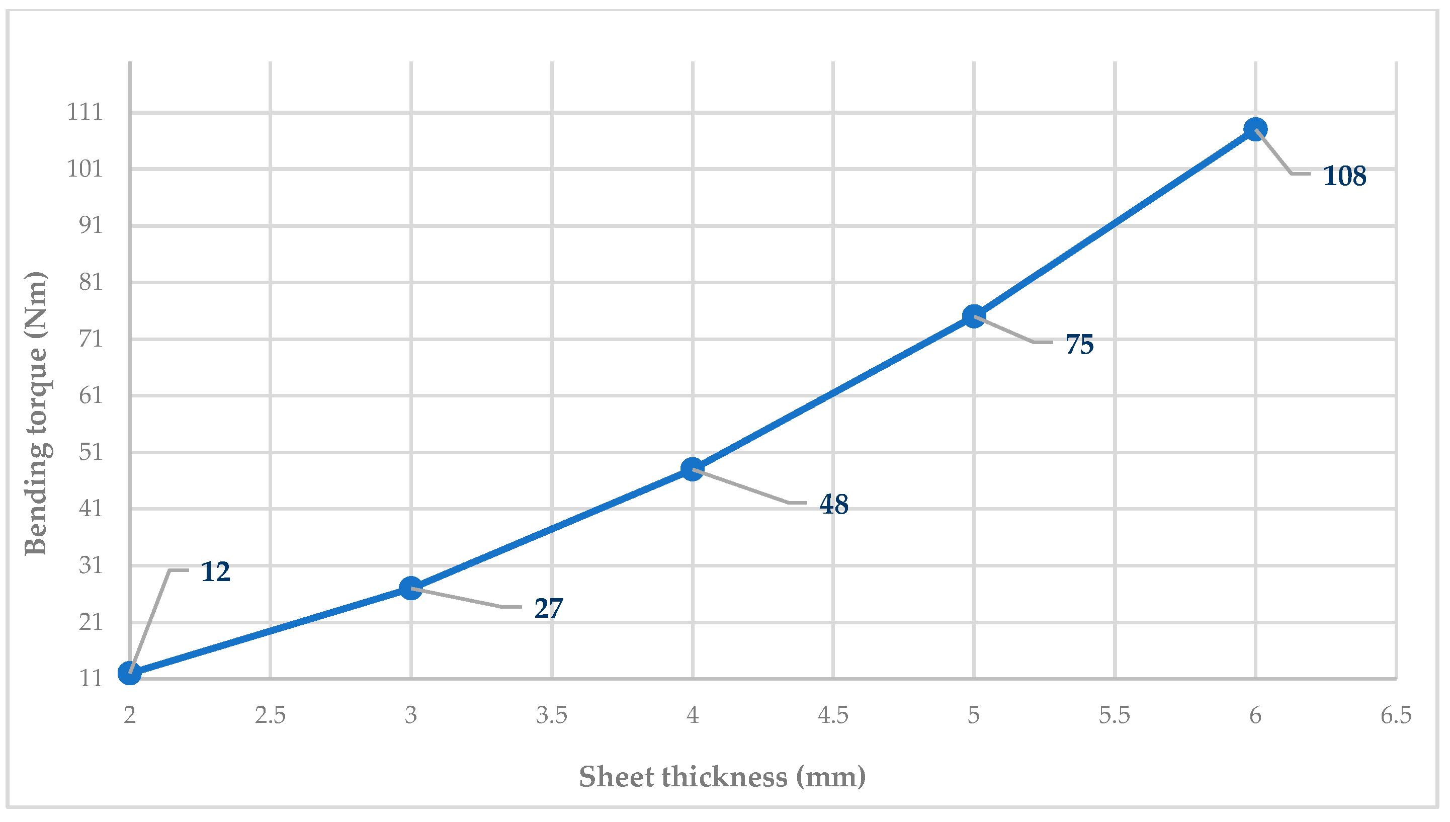
The parabola function shape can be recognized between the changing of the sheet thickness and the bending torques, so the correlation between these parameters is exponential (Figure 14).
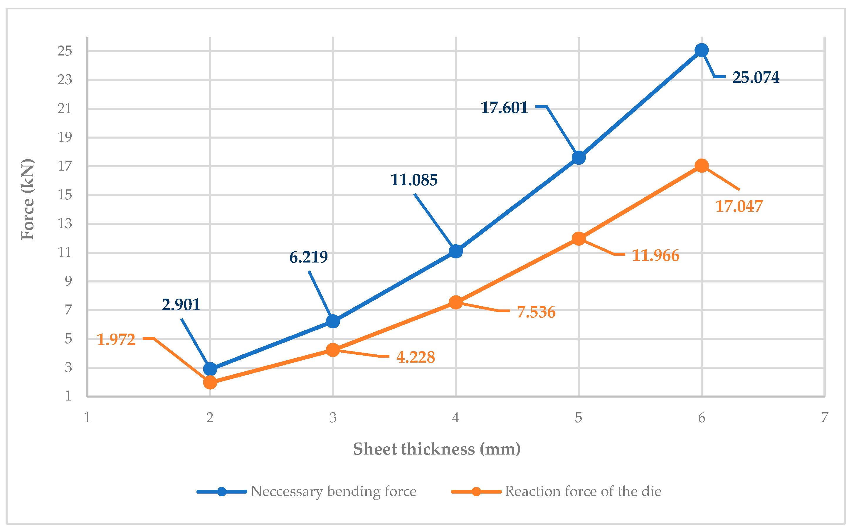
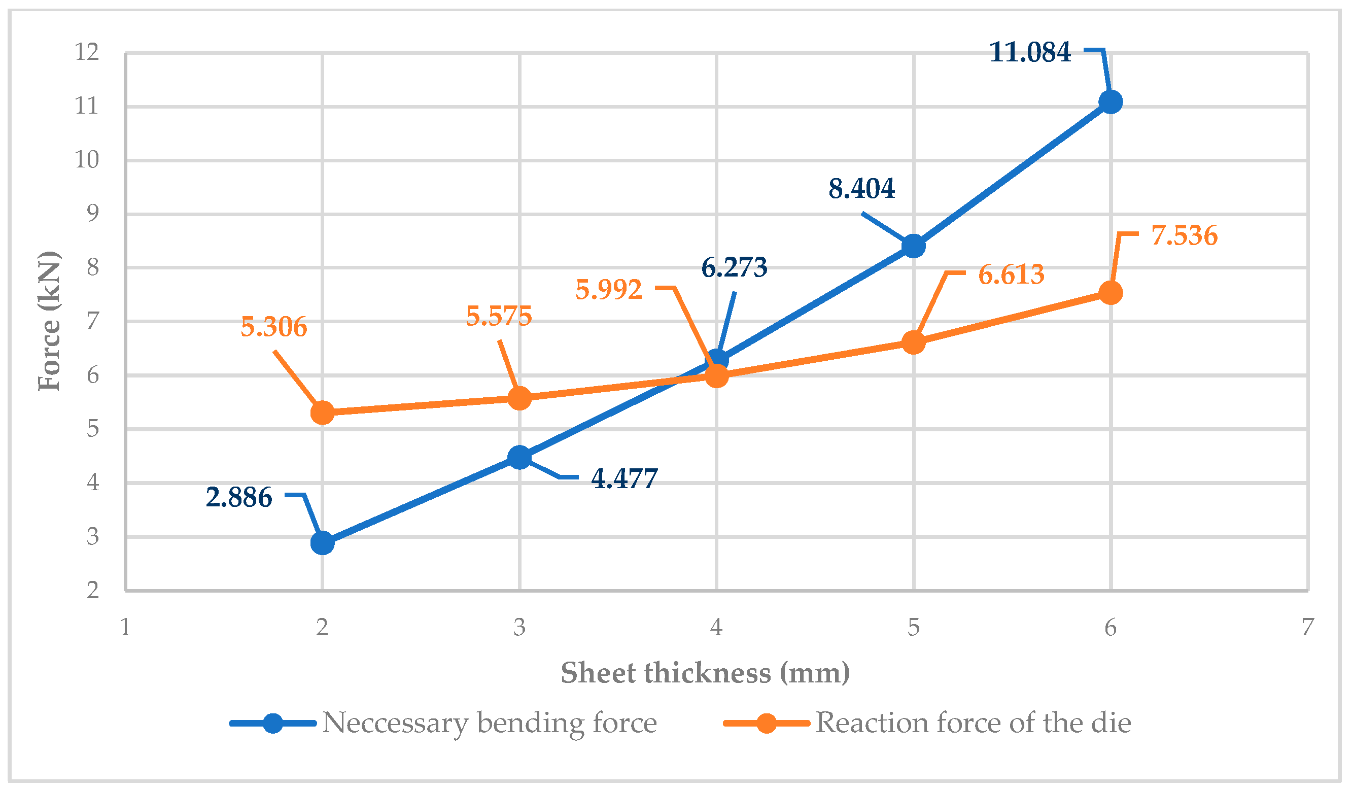
An exponential function that is a parabola can be seen between the changing of the sheet thickness and the forces (necessary bending force and reaction force of the die) in Figure 15. The necessary bending force is always higher than the reaction force of the die.

3.3. Experiment III

The variable is the bending angle (α). The initial and the calculated parameters are in Table 3.
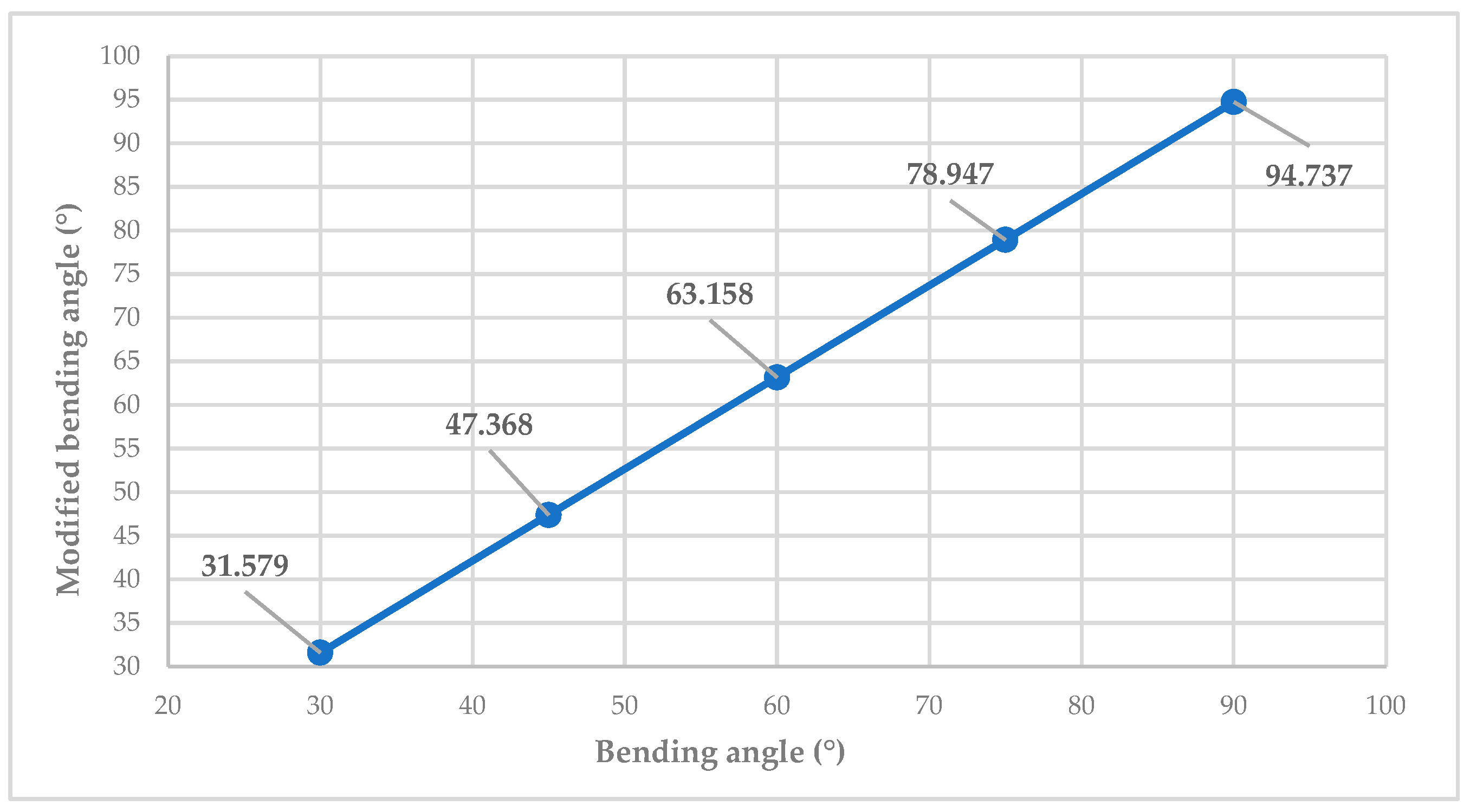
The shape of the function is linear, so there is a linear proportion between the changing of the bending angle and the calculated modified bending angle (Figure 16).
The necessary bending force and the reaction force of the die have an exponential correlation with the changing of the bending angle. The reaction force of the die is larger than the necessary bending force in the case of 30° and 45° bending angles. After that it is inverted, so the necessary bending force is larger than the reaction force (Figure 17).

3.4. Experiment IV

The variable is the sheet width (b). The initial and the calculated parameters are in Table 4.
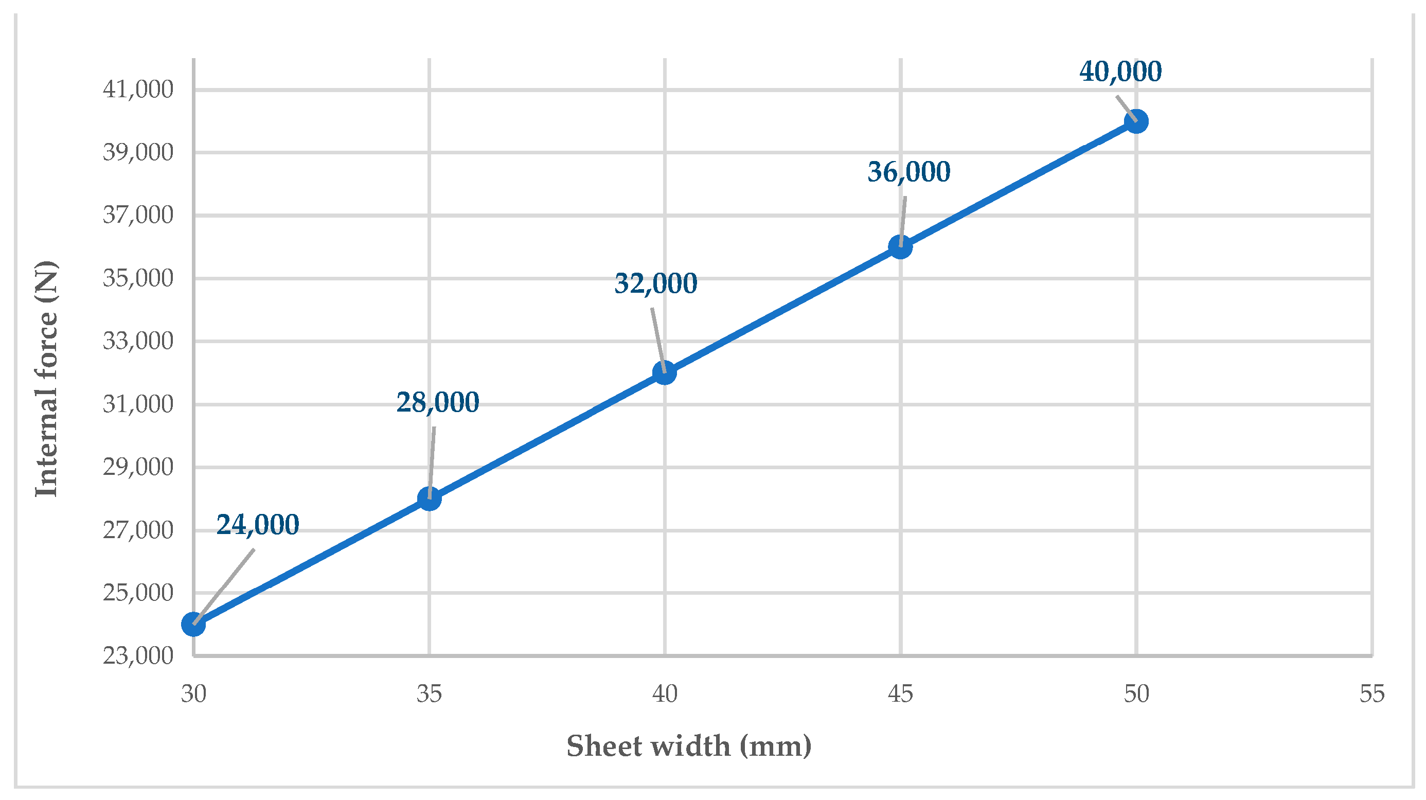
The shapes of the functions are linear in Figure 18 and Figure 19. A linear proportion can be seen in both cases where the received parameters are the internal force and the bending torque.
The function shape between the sheet width and the forces is also linear. The necessary bending force is always larger than the reaction force of the die (Figure 20).

4. Discussion

Based on the referenced literature, the entire bending technology was analyzed in a clear and comprehensive manner. During the analysis, new illustrative figures were introduced to support understanding by visually presenting the technological processes. Additionally, the formulas related to bending were explained in a clear and logical way, contributing to a deeper theoretical and practical understanding of the technology. It is useful for both university education and industrial application and technological design.
The effect of the changing of one important technological parameter was analyzed on four experiments for the determined technological parameters to determine the significance of the variable. Based on the shape of the functions, it is possible to conclude the importance of the variable technological parameter for the technological process. In addition, this study can serve as a valuable resource for manufacturing designers by providing insights into how various process parameters—such as material properties, tool geometry, bending speed, and temperature—affect the overall technological process. Through detailed analysis and interpretation of these effects, designers can make more informed decisions when developing or optimizing bending operations. This contributes not only to improving the efficiency and accuracy of the manufacturing process but also to enhancing the overall understanding of bending technology, both from theoretical and practical perspectives. There are a lot of possibilities to continue this research:
  • Finite Element Analysis (FEA) during the metal forming process can be conducted using either a static or dynamic approach. In the static method, the analysis assumes that the load is applied slowly and steadily, without considering inertial effects, which is suitable for processes where deformation occurs gradually. On the other hand, the dynamic method takes into account time-dependent factors, including inertia and impact forces, making it more appropriate for high-speed or sudden deformation processes. The choice between static and dynamic analysis depends on the specific characteristics of the forming operation being studied.
  • Various types of bending tools can be designed and modeled depending on the specific requirements of the bending process. These tools can be tailored to different material properties, bending angles, and product geometries. Through computer-aided design (CAD) and simulation techniques, such as Finite Element Analysis (FEA), the performance of these tools can be evaluated and optimized before physical production. This allows for improved accuracy, reduced material waste, and enhanced process efficiency in practical applications.
  • A wider range of materials can be analyzed to investigate how different technological parameters—such as bending speed, tool geometry, temperature, and material thickness—affect their behavior during the forming process. By conducting simulations or experiments on various materials, the influence of these parameters can be thoroughly examined. The results can then be compared to identify material-specific responses, optimize process conditions, and support the selection of the most suitable material for a given application. This comparative analysis contributes to a better understanding of material performance and process efficiency.
  • The manufacturing design and detailed analysis of the individual components of the designed bending tool can also represent a valuable and promising research direction. This includes the geometric and material design of parts such as punches, dies, and supports, as well as their structural behavior under operational loads. By applying advanced modeling techniques, such as CAD and Finite Element Analysis (FEA), researchers can optimize the tool components for durability, precision, and performance. Additionally, studying the manufacturing processes used to produce these components—such as machining, heat treatment, or surface finishing—can further enhance the overall efficiency and quality of the bending tool system.

5. Conclusions

The first part of this publication focuses on a methodological, applied, and secondary research approach, in which the entire technological design process is thoroughly explained. This is intended to assist manufacturing engineers in their design work, using references as a foundation. New manufacturing diagrams are introduced, and the relationships between the various formulas are made clear, allowing for a deeper understanding of the underlying technology.
This part presents an innovative methodological framework by systematically combining applied and secondary research approaches to support manufacturing engineering design. The first part introduces a novel, structured interpretation of the technological design process, supported by newly developed manufacturing diagrams and clarified interrelationships among formulas. This contributes to a more comprehensive understanding of bending technologies and provides engineers with a practical, reference-based foundation for their design work—a notable methodological advancement in the field.
The second part of the publication provides a manufacturing analysis aimed at identifying the relationships between selected variable parameters and the resulting technological outcomes. Four key experiments were conducted to assess the most critical initial manufacturing parameters. The findings of these experiments offer valuable insights for manufacturing designers, helping them understand the interactions between crucial parameters and enabling them to select the most optimized settings for executing the technology.
Based on formula (2), it is determinable that the neutral radius depends on the sheet thickness. The ratio between them is a linear proportion.
The second part delivers a scientifically grounded experimental analysis that explores the interactions between initial manufacturing parameters and technological outcomes. By varying one geometric parameter per experiment across four distinct trials, the study reveals how critical input variables—such as sheet thickness, bending radius, angle, and width—affect process performance. One particularly valuable theoretical contribution is the confirmation of a linear relationship between sheet thickness and the neutral radius, based on Formula (2).
This research holds significant value both from a theoretical perspective and for industrial applications. The combination of structured methodology, new visual tools (diagrams), and experimental validation makes this research both theoretically relevant and practically applicable in industrial contexts. It enables manufacturing designers to better predict and optimize process parameters, contributing to efficiency, accuracy, and technological innovation.

Author Contributions

Mathematical analysis, G.S.; Technological analysis, S.B.; Analysis of the technological parameters, S.B.; Experiments, S.B. and G.S.; Evaluation of the results, S.B. and G.S.; All authors have read and agreed to the published version of the manuscript.

Funding

This research received no external funding.

Data Availability Statement

The data presented in this study are available on request from the corresponding author.

Acknowledgments

Supported by the University of Debrecen Program for Scientific Publication.

Conflicts of Interest

The authors declare no conflict of interest.

Abbreviations

SymbolNameUnit
l ^ arc length[mm]
bsheet width[mm]
Fthe necessary bending force[N]
Fminternal force[N]
Frthe reaction force of the die[N]
Kspringback factor
k, jrunning index numbers
kfflow stress[MPa]
Lcover length[mm]
llength of the linear section on the part[mm]
Mbending torque[Nm]
Miinternal torque[Nm]
Moexternal torque[Nm]
Obending center point
riinner bending radius[mm]
ri_vmodified inner bending radius[mm]
rmmiddle radius[mm]
rnneutral radius[mm]
roouter bending radius[mm]
ssheet thickness[mm]
xthe distance between the line of action of the reaction force of the die and the intersection point of the center line of the punch and the neutral strand[mm]
αbending angle[°]
α_vmodified bending angle[°]
ββ factor of the workpiece material
ξbending factor

References

  1. Skriba, Z. Fémek Képlékeny Alakítása, 3rd ed.; Tankönyvkiadó: Budapest, Hungary, 1966; p. 429. [Google Scholar]
  2. Gulyás, J.; Pintér, K.; Kiss, E.; Reisz, G.; Mecseki, I.; Tóth, L.; Voith, M. Képlékenyalakítás; Tankönyvkiadó: Budapest, Hungary, 1987; p. 691. ISBN 963 17 9492 X. [Google Scholar]
  3. Yang, H.; Li, H.; Zhang, Z.; Zhan, M.; Liu, J.; Li, G. Advances and Trends on Tube Bending Forming Technologies. Chin. J. Aeronaut. 2012, 25, 1–12. [Google Scholar] [CrossRef]
  4. Gantner, P.; Bauer, H.; Harrison, D.K.; De Silva Anjali, K.M. Free-Bending—A new bending technique in the hydroforming process chain. J. Mater. Process. Technol. 2005, 167, 302–308. [Google Scholar] [CrossRef]
  5. Gantner, P.; Harrison, D.K.; De Silva, A.K.M.; Bauer, H. New Bending Technologies for the Automobile Manufacturing Industry. In Proceedings of the 34th International MATADOR Conference, Manchester, UK, 7–9 July 2004; Hinduja, S., Ed.; Springer: London, UK, 2004. [Google Scholar] [CrossRef]
  6. El-Aty, A.A.; Guo, X.; Lee, M.-G.; Tao, J.; Hou, Y.; Hu, S.; Li, T.; Wu, C.; Yang, Q. A review on flexibility of free bending forming technology for manufacturing thin-walled complex-shaped metallic tubes. Int. J. Lightweight Mater. Manuf. 2023, 6, 165–188. [Google Scholar] [CrossRef]
  7. Liang, J.; Gao, S.; Teng, F.; Yu, P.; Song, X. Flexible 3D stretch-bending technology for aluminum profile. Int. J. Adv. Manuf. Technol. 2014, 71, 1939–1947. [Google Scholar] [CrossRef]
  8. Li, Y.; Han, X.; Liang, J.; Teng, F.; Liang, C. Effect of multi-point roller dies on the forming accuracy of profile in flexible 3D stretch bending technology. Int. J. Adv. Manuf. Technol. 2021, 112, 897–905. [Google Scholar] [CrossRef]
  9. Zaragoza, V.G.; Strano, M.; Iorio, L.; Monno, M. Sheet metal bending with flexible tools. Procedia Manuf. 2019, 29, 232–239. [Google Scholar] [CrossRef]
  10. Yang, J.-B.; Jeon, B.-H.; Oh, S.-I. The tube bending technology of a hydroforming process for an automotive part. J. Mater. Process. Technol. 2001, 111, 175–181. [Google Scholar] [CrossRef]
  11. Chen, H.; Wang, H.; Abd El-Aty, A.; Qin, Y.; Li, J.; Zhang, Y.; Li, T.; Guo, X. Impact of bending dies with different friction forms on forming force and quality of tubes manufactured by free bending technology. Chin. J. Aeronaut. 2021, 34, 253–264. [Google Scholar] [CrossRef]
  12. Welo, T.; Wideroe, F. Precision bending of high-quality components for volume applications. Trans. Nonferrous Met. Soc. China 2010, 20, 2100–2110. [Google Scholar] [CrossRef]
  13. Yang, S.; Li, Y.; Liang, J.; Wen, Y.; Liang, C.; Han, Q. Adaptive multi-point flexible-bending technology for improving the quality of profile using discrete dies driven by snake-shaped motion mechanism. J. Mater. Process. Technol. 2024, 325, 118297. [Google Scholar] [CrossRef]
  14. Stiller, T.; Kerschbaumer, R.C.; Waly, C.; Zink, B.; Slapnik, J.; Pinter, G. Investigating the influence of bending stiffness and processing parameters on single-leg bending geometries of additively manufactured composites. Results Eng. 2024, 24, 103276. [Google Scholar] [CrossRef]
  15. Karfidov, A.O.; Chichenev, N.A.; Vasil’ev, M.V.; Chicheneva, O.N. Production of arc sheet elements by stepped bending method. Izvestiya. Ferr. Metall. 2025, 68, 233–238. [Google Scholar] [CrossRef]
  16. Li, H.; Zhu, Y.; Chen, W.; Yuan, C.; Wang, L. Advanced Bending and Forming Technologies for Bimetallic Composite Pipes. Materials 2025, 18, 111. [Google Scholar] [CrossRef] [PubMed]
  17. Ahemad, M.W.; Palani, I.A.; Joshi, S.S. Investigation on multiple bending using laser forming of mild steel plate and its bend angle prediction. J. Micromanuf. 2025. [Google Scholar] [CrossRef]
  18. Neuman, W.L. Social Research Methods: Qualitative and Quantitative Approaches, 7th ed.; Pearson Education Limited: Harlow, UK, 2014; ISBN 9781292020235. [Google Scholar]
  19. Patton, M.Q. Qualitative Research & Evaluation Methods, 3rd ed.; Sage Publications: Thousand Oaks, CA, USA, 2002; ISBN 9780761919711. [Google Scholar]
  20. Hunyady, G. (Ed.) Társadalomtudományi Kutatások Módszertana; Osiris Publisher: Budapest, Hungary, 2002; ISBN 963389429X. [Google Scholar]
  21. Creswell, J.W. Research Design: Qualitative, Quantitative, and Mixed Methods Approaches, 4th ed.; SAGE Publications: Thousand Oaks, CA, USA, 2014; ISBN 9781452226101. [Google Scholar]
  22. Babbie, E. The Practice of Social Research, 12th ed.; Wadsworth Cengage Learning: Belmont, CA, USA, 2010; ISBN 9780495598411. [Google Scholar]
  23. Saunders, M.; Lewis, P.; Thornhill, A. Research Methods for Business Students, 7th ed.; Pearson Education Limited: Harlow, UK, 2016; ISBN 9781292016627. [Google Scholar]
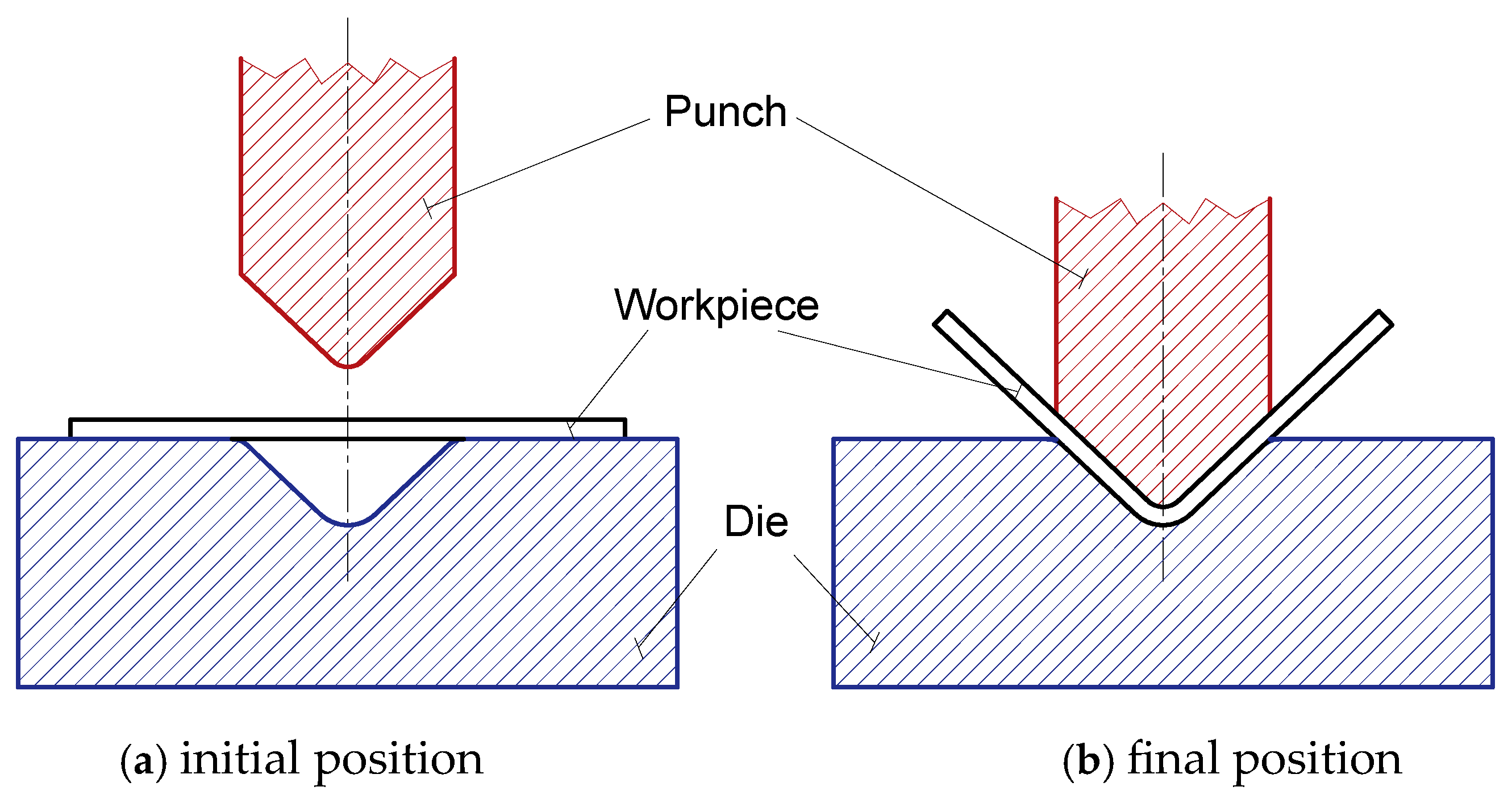
Figure 1. Execution of the bending process.
Jmmp 09 00272 g001
Figure 2. Deformation status of elastic bending.
Jmmp 09 00272 g002
Figure 3. Deformation status of plastic bending.
Jmmp 09 00272 g003
Figure 4. Determination of the cover length and the geometric shape of the workpiece.
Jmmp 09 00272 g004
Figure 5. The theorem of springback.
Jmmp 09 00272 g005
Figure 6. The equilibrium of the internal forces.
Jmmp 09 00272 g006
Figure 7. The equilibrium of the external forces.
Jmmp 09 00272 g007
Figure 8. Chart function of the inner bending radius and the neutral radius.
Jmmp 09 00272 g008
Figure 9. Chart function of the inner bending radius and modified bending radius.
Jmmp 09 00272 g009
Figure 10. The correlation between the inner bending radius and the forces.
Jmmp 09 00272 g010
Figure 11. The correlation between the sheet thickness and the neutral radius.
Jmmp 09 00272 g011
Figure 12. The correlation between the sheet thickness and the modified bending radius.
Jmmp 09 00272 g012
Figure 13. The correlation between the sheet thickness and the internal force.
Jmmp 09 00272 g013
Figure 14. The correlation between the sheet thickness and bending torque.
Jmmp 09 00272 g014
Figure 15. The correlation between the sheet thickness and the forces of the metal forming process.
Jmmp 09 00272 g015
Figure 16. The correlation between the bending angle and the modified bending angle.
Jmmp 09 00272 g016
Figure 17. The correlation between the bending angle and the forces of the metal forming process.
Jmmp 09 00272 g017
Figure 18. The correlation between the sheet width and the internal force.
Jmmp 09 00272 g018
Figure 19. The correlation between the sheet width and the bending torque.
Jmmp 09 00272 g019
Figure 20. The correlation between the sheet width and the forces of the metal forming process.
Jmmp 09 00272 g020
Table 1. The effect of the changing of the inner bending radius.
Inner bending radius (ri)4 mm6 mm8 mm10 mm12 mm
Sheet thickness (s)4 mm
Bending factor (ξ)0.961
Bending angle (α)90°
Springback factor (K)0.95
Modified bending angle (αm)94.737
Middle radius (rm)6 mm8 mm10 mm12 mm14 mm
Outer radius (ro)8 mm10 mm12 mm14 mm16 mm
Sheet width (b)30 mm
Internal force (Fm)24 kN
Bending torque (M)48 Nm
Table 2. The effect of the changing of the sheet thickness.
Inner bending radius (ri)8 mm
Sheet thickness (s)2 mm3 mm4 mm5 mm6 mm
Bending factor (ξ)0.980.940.70.50.45
Bending angle (α)90°
Springback factor (K)0.95
Modified bending angle (αm)94.737
Middle radius (rm)9 mm9.5 mm10 mm10.5 mm11 mm
Outer radius (ro)10 mm11 mm12 mm13 mm14 mm
Sheet width (b)30 mm
Table 3. The effect of the changing of the bending angles.
Inner bending radius (ri)8 mm
Sheet thickness (s)4 mm
Bending factor (ξ)0.7
Bending angle (α)30°45°60°75°90°
Springback factor (K)0.95
Middle radius (rm)10 mm
Outer radius (ro)12 mm
Modified bending angle (αm)7.53 mm
Sheet width (b)30 mm
Internal force (Fm)24 kN
Bending torque (M)48 Nm
Table 4. The effect of the changing of the bending width.
Inner bending radius (ri)8 mm
Sheet thickness (s)4 mm
Bending factor (ξ)0.7
Bending angle (α)90°
Springback factor (K)0.95
Middle radius (rm)10 mm
Outer radius (ro)12 mm
Modified bending angle (αm)7.53 mm
Sheet width (b)30 mm35 mm40 mm45 mm50 mm
Disclaimer/Publisher’s Note: The statements, opinions and data contained in all publications are solely those of the individual author(s) and contributor(s) and not of MDPI and/or the editor(s). MDPI and/or the editor(s) disclaim responsibility for any injury to people or property resulting from any ideas, methods, instructions or products referred to in the content.