Article

Influence of Structural Components on Thermal Deformations in Large Machine Tools

by
Álvaro Sáinz de la Maza García
*,
Leonardo Sastoque Pinilla
and
Luis Norberto López de Lacalle Marcaide
Aeronautics Advanced Manufacturing Centre (CFAA), University of the Basque Country (UPV-EHU), Technology Park of Biscay, Building 202, 48170 Zamudio, Spain
*
Author to whom correspondence should be addressed.
J. Manuf. Mater. Process. 2025, 9(8), 267; https://doi.org/10.3390/jmmp9080267
Submission received: 10 July 2025 / Revised: 30 July 2025 / Accepted: 6 August 2025 / Published: 8 August 2025

Abstract

In sectors that require large components with tight tolerances, the control of machine thermal deformations as a result of ambient temperature variations, motor consumption, and heating of moving components is essential. There are many alternatives for modelling and trying to compensate for this deformation, but structural components are rarely analysed independently to study their influence on positioning errors. This study analysed component temperature and deformation measurements using 49 thermocouples and 14 integral deformation sensors (IDS) installed on a large-scale machine tool. The effect of each heat source on component deformations was studied and those with a predominant effect were identified. The results can ease thermal effect prediction models development and new machine design process to maximise accuracy by focusing effort on the most critical components and most important heat sources. It was found that ambient temperature variations lead to greater but more uniform deformations than internal heat sources, reaching a 60% of total deformations with smaller temperature changes (8.7 °C, against 15–35 °C due to internal heat sources). These deformations are localized mainly in the machine bed (100 μ m in X direction and 170 μ m in the Y direction) and column (150 μ m in the Z direction) and in the axis ball screw bearings (reaching 55 °C). Consequently, it is concluded that improving bearing and motor refrigeration could significantly reduce thermally-induced deformations.

Graphical Abstract

1. Introduction

In certain industrial sectors such as aerospace, it is necessary to machine large components with strict tolerances, requiring precise, large-scale machines. In these machines, thermally-induced deformations caused by ambient temperature variations and internally generated heat [1] tend to be significant and unacceptable, accounting for up to 75% of total positioning errors [2].
Given the relative significance of thermally-induced errors, numerous authors have proposed thermal error compensation models aimed at improving the accuracy and repeatability of machine tools [3]. Early efforts predominantly focused on regression-based methodologies, employing either single or multiple variables to achieve substantial error reductions. For example, Q. Li and H. Li [4] applied least-square regression methods to compensate for spindle thermal error, obtaining high prediction accuracy. Similarly, J. Liu et al. [5] developed a comprehensive data-driven thermally-induced error compensation method suitable for high-speed and high-precision five-axis machine tools, achieving about an 80% error reduction. These results highlight the effectiveness of regression-based modelling approaches under controlled conditions.
Neural-network-based methodologies have also been widely explored as a viable alternative to regression models, leveraging their capacity to handle the complex and nonlinear relationships inherent in thermal deformation phenomena. A compelling example is the study by Yin et al. [6], who implemented a selective ensemble of backpropagation (BP) neural networks combined with fuzzy c-means clustering for selecting thermal sensitive points along with a genetic algorithm to evolve the model weights. The resulting IPSO-BP model achieved a prediction accuracy of 96.5% for the spindle thermal error, markedly outperforming both single BP networks and least-square support vector machine (LS-SVM) models. Similarly, H. Yau et al. [7] employed advanced transfer learning-based long short-term memory (LSTM) neural networks, attaining compensation accuracy of approximately 75%. These neural network models have demonstrate robustness against thermal variations and represent a substantial advancement over traditional regression methods, particularly when dealing with complex thermal behaviours that might be difficult to characterise analytically.
More recently, innovative approaches involving digital twins and advanced sensor integration have further enhanced error compensation capabilities. B. Iñigo et al. [8] exemplified the potential of digital twin technologies in achieving high-fidelity volumetric thermal error compensation, providing continuous and dynamic model updates through virtual simulations closely linked to physical systems. Using the same large-scale machining centre employed in the present research, Á. Sáinz de la Maza García et al. [9] presented a compensation model that integrated experimental data from three thermocouples or IDS bars. Using a dedicated metrological artefact for measurement [10], their results demonstrated prediction accuracy slightly exceeding 75%. Complementing empirical approaches, alternative research lines have studied detailed machine modelling and thermal simulation methods, as reported by M. Ess [11] and W. Ye et al. [12], as well as analytical models that offer theoretical insights into thermally induced deformations, notably described by L. Weng et al. [13] and W. L. Chu et al. [14].
Data-driven models do not require detailed knowledge of the machine structure or understanding of which components experience the greatest deformation, whereas physical or simulation-based models consider each component individually along with their influence on positioning errors [15,16]. When comparing these two kinds of techniques, it could be said that physical models can generally achieve very high error prediction accuracy with an outstanding robustness, being adequate to work with thermal states that were not seen before; however, the main limitation of these models is the higher expertise needed to generate them. In contrast, data-driven models are easier to generate, especially when using neural networks or machine learning approaches, but require a large dataset with information about the most probable working conditions of the machine. These models generally lead to excellent results for conditions close to those used during the training or adjustment stage, but may become unstable as working conditions move further from those in the dataset obtained by testing [17,18]. Additionally, in the case of data-driven models, a large dataset is needed to adequately adjust the model, which requires more data as its complexity increases. Obtaining such large amounts of data can be costly and inefficient [19].
With physical models in mind, in this research we performed multiple heating tests on a large-scale machine equipped with 49 thermocouples and 14 integral deformation sensors (IDS) installed on its structural components. The influence of each heat source and ambient temperature was studied.
To summarize the main idea of using temperature and deformation sensors, Figure 1 shows a brief mind map indicating the main sources of TCP positioning errors in machine tools, which in turn induce workpiece geometric errors during manufacturing operations. TCP errors are mainly due to thermal effect, kinematic errors, control-related issues, and cutting force-induced deformations. Additionally, when the machine is moving, dynamic deformations due to inertia may appear, leading to an increase in positioning errors. This research is limited to studying the first source of positioning errors, as it is the most severe in large machine tools. These thermal errors may be a consequence of ambient temperature changes or other environmental changes; alternatively, they may be due to internal heat sources (or sinks, in the case of cooling systems). During this research, the use of IDS sensors allowed us to directly measure thermally-induced deformations in structural components, while internal heating and ambient temperature changes were measured using thermocouples. All of these sensors were connected to an internal server consisting of fog computing infrastructure, as described in [20], where all data were recorded. Ambient temperature variations were measured but could not be effectively controlled in the workshop where this research was conducted. The same was the case with the refrigeration system, which acts as a heat sink that is not controllable by the research team. On the other hand, internal heat sources were easy to vary by moving machine axes and spindles.
In this work, it was found that for large machining centres, ambient temperature variations have a larger but more uniform effect on machine deformations than internal heat sources. In fact, the ambient temperature varied less than 9 °C, much less than the 35 °C increase measured in some moving components, but led to about a 60% of total deformation. The main structural components causing positioning errors were the machine bed and column, with deformations of 100 to 170 μ m, while the elements most affected by movements of the axes were the ball screw bearings and nuts, with temperature increases of up to 35 °C. These results can allow machine tool manufacturers to improve their designs for future products.
Thermal issues in machine tools are a well-known research topic in the manufacturing industry, and many different approaches have been proposed to reduce or compensate for their effects. However, it is very uncommon to study how each structural element is deformed due to ambient temperature changes and internal heat sources. Moreover, previous works studying structural components deformations have mostly been based on finite element method (FEM) simulations due to their simplicity and low cost. However, machine tool manufacturers lack scientific research in this line using real-life experimental testing that measures not only TCP errors or internal temperatures but also analyses real component deformation. This study aims to cover this gap in the research environment by using IDS sensors, which provide interesting data for new machine tool designs but are very rarely used due to their high cost and complexity. Previous examples have been proposed by C. Brecher et al. [21] and C. Baum et al. [22], both of which were based on estimating TCP positioning error by using IDS measurements to compensate for thermal deformations but without indicating the deformations suffered by each component.

2. Materials and Methods

This section describes the equipment used in this research and the procedures for obtaining temperature and deformation data.

2.1. Machine

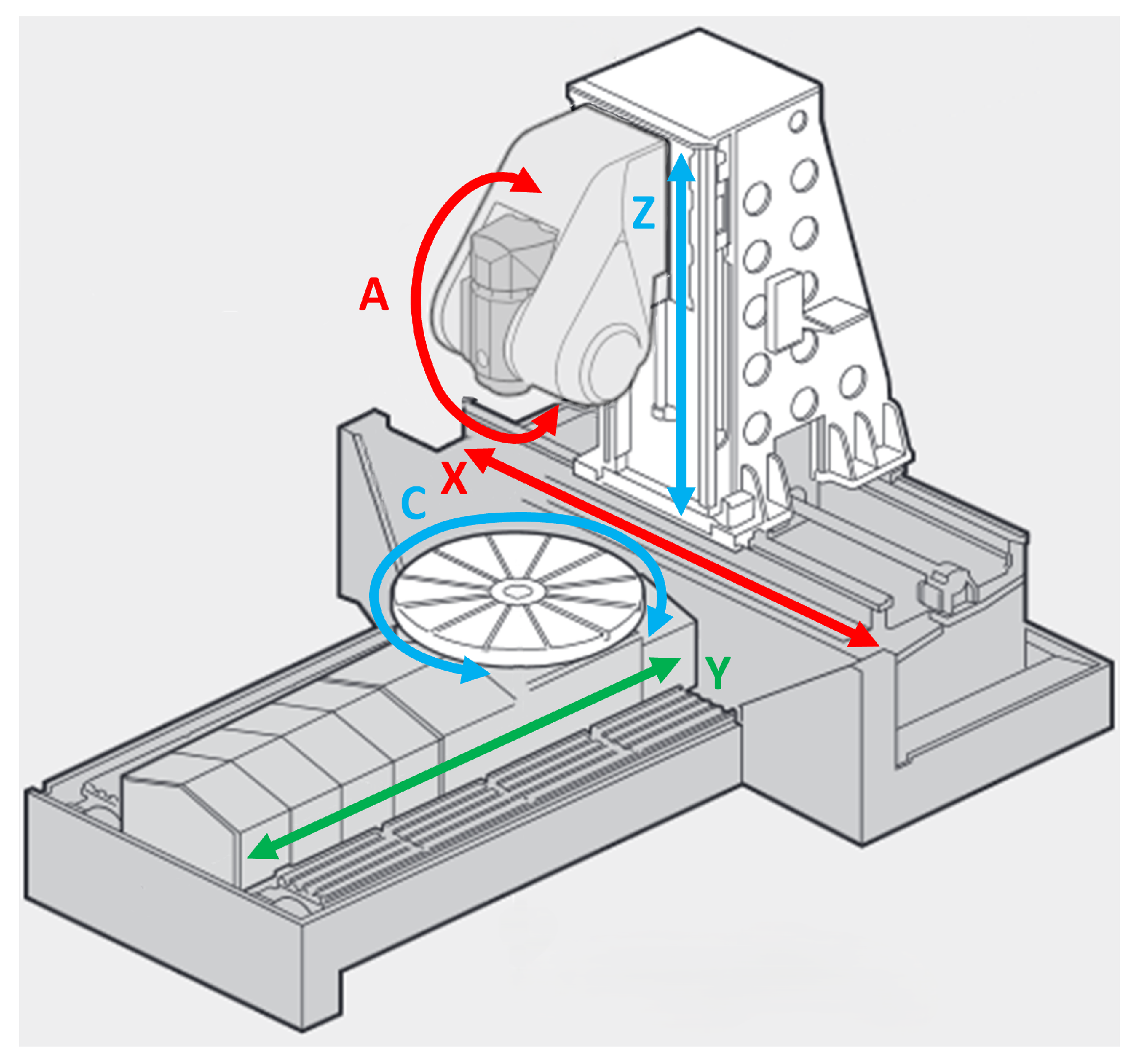
All tests were performed on a five-axis large-scale multi-process machine with an RLLLR configuration (two rotary axes, designated A and C, and three linear axes, designated X, Y, and Z) capable of milling, turning, and grinding. The turning table has a diameter of 1250 mm. The travel ranges of the linear axes are 1620 mm (X), 1310 mm (Y), and 1500 mm (Z), while the head tilt axis (A) ranges from −135 ° to 45 °, including vertical and horizontal positions. Figure 2 shows the machine and its linear and rotary axes.
The machine is equipped with an 84 kW electrospindle with a maximum speed of 12,000 rpm. The rotary table drive (capable of turning) uses a 54.1 kW torque motor reaching 500 rpm. Both motors feature internal cooling systems to maintain stable temperatures. The A-axis drive also uses a cooled torque motor. All three motors share a cooling circuit that operates cyclically, maintaining the cooling liquid within two ambient temperature-dependent thresholds.
All linear axes (X, Y, Z) use ball screw drives; however, only the Y and Z axes have rotating screws. For the X-axis, rotation occurs at the nut, while the screw remains stationary. The Y-axis motor is directly coupled to the screw, whereas the X and Z axes employ toothed belt transmissions. None of these linear drives have internal cooling.

2.2. Installed Sensors

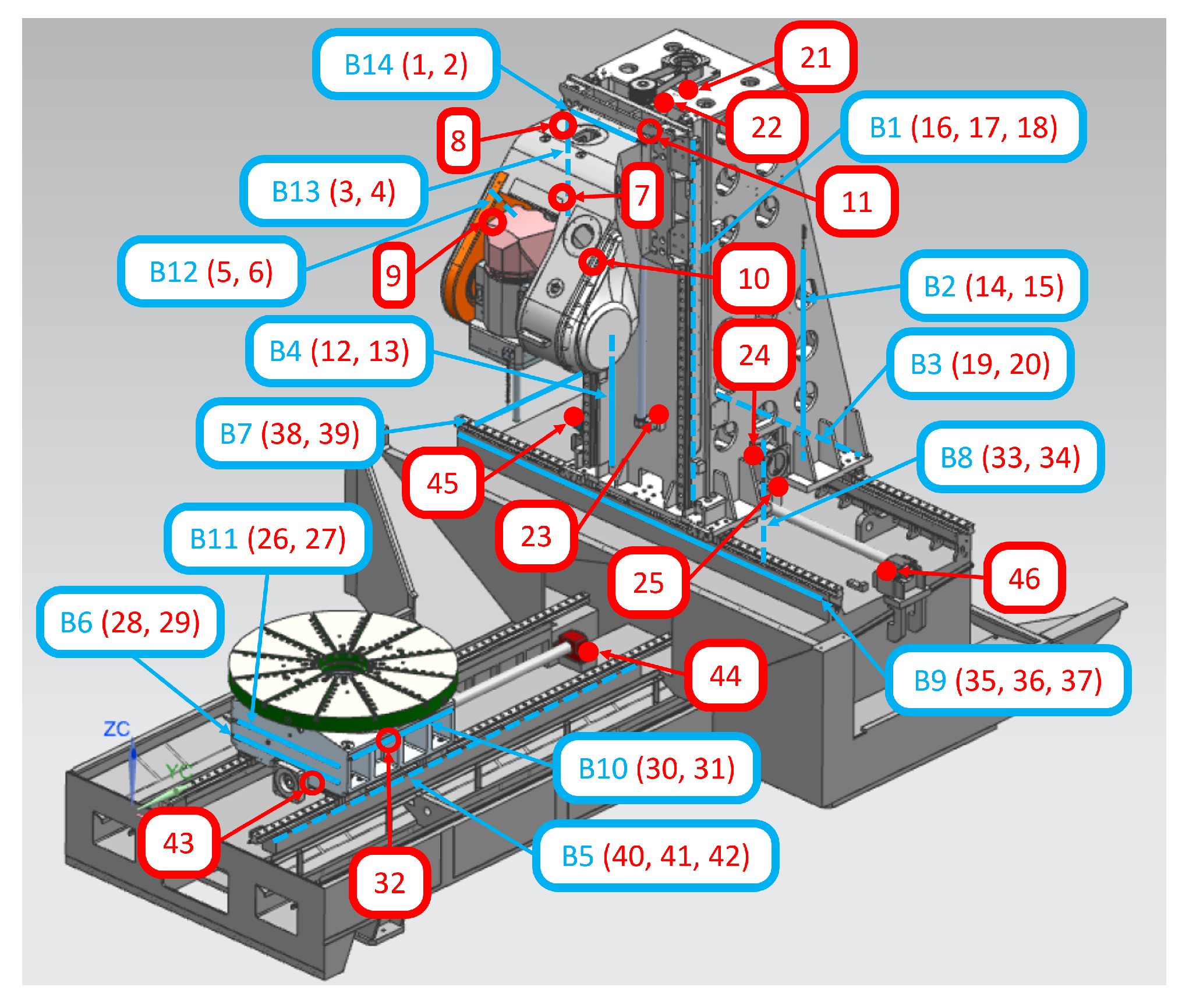
For this study, temperatures at multiple points and deformations of major structural components were monitored (Figure 3). Ambient temperature was measured using three thermocouples (47, 48, 49) placed strategically at different heights in the workshop, near the machine but avoiding air current influence, allowing for air stratification analysis. Measuring the machine component temperatures required installing 46 thermocouples in critical thermal areas, along with internal motor temperature sensors; this configuration allowed us to detect both ambient-induced structural changes and localised heat sources, including motors, guides, bearings, and other energy-intensive components.
Although machine tool temperature monitoring is not common in industry, structural component deformation measurement is even rarer. Structural deformation analysis aims at global behaviour rather than localised areas prone to stress concentration effects or very local heat sources. Thus, traditional strain gauges were discarded in favour of fourteen integral deformation sensors. Each IDS comprised a composite bar of known length with minimal thermal expansion and a linear variable displacement transducer (LVDT). One bar end was rigidly attached to the monitored component, while the other rested freely in a second support keeping the LVDT in place and fixed to the component, allowing for relative displacement of the bar and the LVDT. As thermal effects on the bar are much lower than on machine structural components, this setup directly measures component deformation. For longer bars, a central support was employed to reduce lateral vibrations. A more detailed description of IDS sensors is provided by C. Naumann et al. [23].
Even though they measure different physical variables, IDS sensors and thermocouples provide complementary information. In fact, due to the prohibitive cost of IDS sensors for production environments, thermocouples were installed at each IDS support to assess whether lower-cost thermocouples could replace IDS measurements to enable real-time deformation prediction and correction models. IDS sensors have 1 μ m resolution, while thermocouples have 0.1 C resolution.

2.3. Data Acquisition System

Given the large sensor count and data volume, the data acquisition system is complex. Thus, only a global description is introduced in this section; the detailed system was exposed by E. Tapia et al. in [24].
Analog signals from thermocouples and IDS sensors are digitised using multiple acquisition cards. Data are then sent to an industrial PC and subsequently transmitted to an edge device. Additionally, internal CNC parameters (Siemens Sinumerik 840D), including motor power, temperatures, and positions from encoders and optical scales, are collected and directly sent to the edge device.
Using a single timestamp, all data are sent in real-time from the edge device to an internal server at the Aeronautics Advanced Manufacturing Centre (CFAA) using a fog-based approach for privacy. Data are recorded at 1 Hz frequency, which is suitable for thermal analysis due to high thermal inertia. In over 730 h of work, the system recorded more than 420 million data points.

2.4. Conducted Experimental Tests

Numerous tests were performed under varying conditions and ambient temperatures. The main conclusions could be derived from a single representative test per movement type, as trends were consistent across tests. Thus, this paper presents results from six heating cycles, summarised in Table 1, although some conclusions correspond to a broader range of cases, such as movements of the rotary axes.
To study the effect of each axis movement, they were heated independently; additionally, the combined movement of those axes with greater cross-effect (XZ or XYZ combinations) was studied.
Apart from ambient temperature changes and internal heat sources related to axes movements, machining operations may represent an important heat source. As this depends heavily on each operation, it was excluded from this study, representing a finishing operation where material removal rates and cutting power are low.

3. Results and Discussion

This research clarifies which components are most affected by internal and ambient temperature changes, informing large-scale machine-tool design and enabling future thermal error compensation models. Our key results are summarized in this section.
These findings are highly valuable for machine tool manufacturers, and the research was conducted in constant communication with manufacturers in order to investigate those effects for which there is less information available. Using the results of this work, machine tool manufacturers will be able to improve their designs towards more thermally-immune machines.

3.1. Structural Elements Deformations

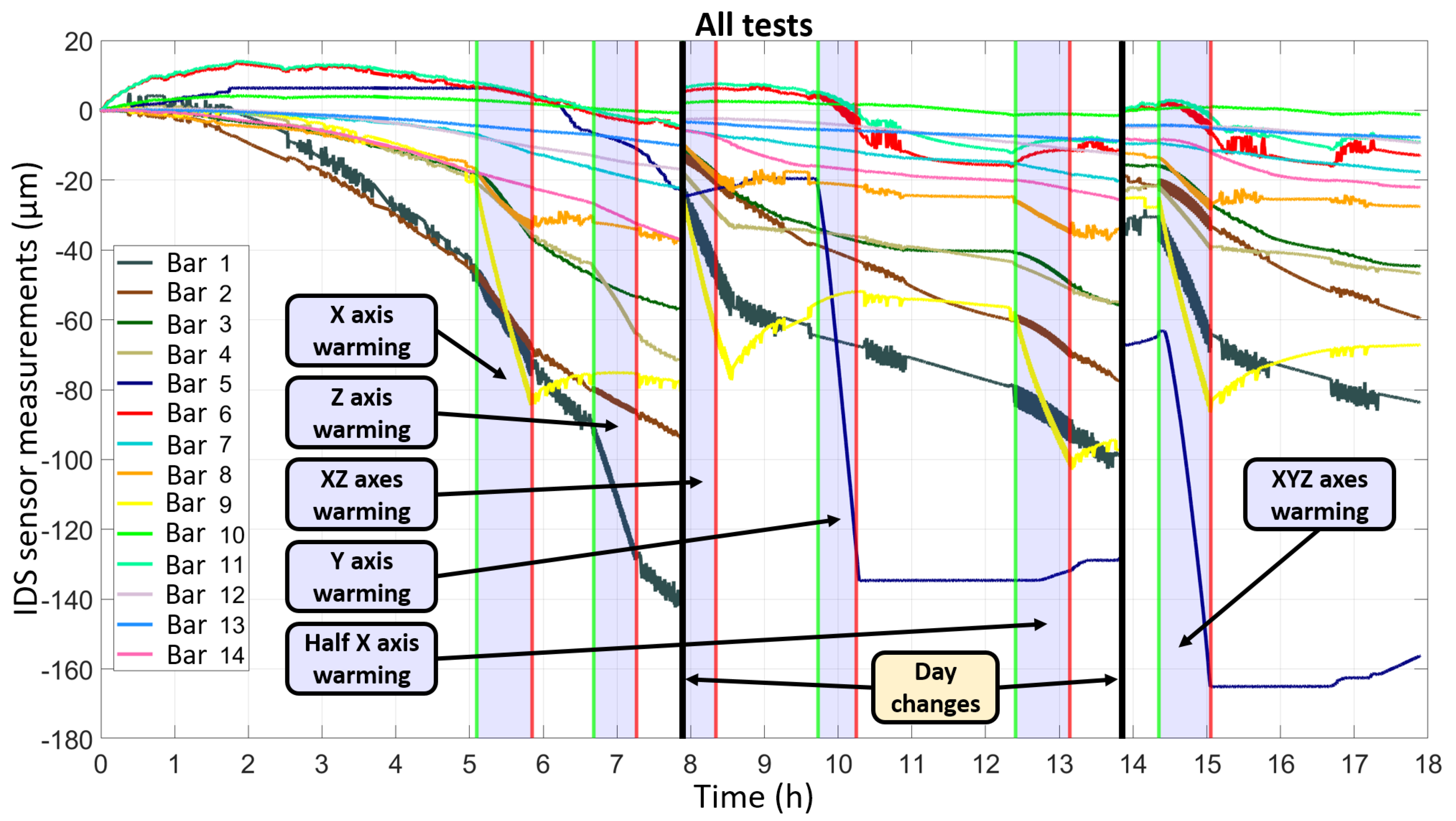
As the main objective in understand machine deformation sources is to prevent them in future designs and compensation models, we first analysed the deformation measurements of the components performed using IDS sensors. The deformations shown in Figure 4 were recorded over the three-day testing period considered in this study. In the figure, vertical black lines represent day changes (no data were collected with the machine switched off), green vertical lines indicate the start of each test, and red lines mark their end. More precisely, measurements were made on three consecutive days, starting and finishing at the times shown in Table 2. Due to the operating principle of IDS sensors, expansion is measured as negative deformation; thus, most recorded deformation values are negative.
Figure 4 clearly illustrates that the signal is very noisy during certain periods, particularly for IDS bar 1, while during others the signal is smoother. This phenomenon, attributable to the cooling system, is described in detail in Section 3.3, and only appears when the machine is powered on. Consequently, less noisy regions correspond to times when the machine was not powered and thus was generating no internal heat. It is observable that the deformations are smaller during these periods compared to the rest of the testing time (e.g., between 11:00 and 12:20, 15:45 and 16:40, and 17:20 and 17:50). Without power, the machine deforms solely due to ambient temperature variations, significantly affecting components that are more exposed to the environment, such as the column. Conversely, when powered on (but still without any movement), internal heating increases component deformation, as evidenced between 2:30 and 5:00.
From Figure 4, it is evident that certain components experience minimal deformation beyond that caused by ambient temperature variation. These include the machine head (bars 12, 13, and 14) and the bed supporting the X-axis in the Y direction (bar 7). Although some deformations are seen during movement, they are small in the moving carriage structure (bars 6, 10, and 11). The head remains thermally stable thanks to spindle cooling, although bar 14 shows slight elongation during Z-axis heating due to its proximity to this axis. Taking into account the small magnitude of these components deformations, the head and moving carriage can be considered adequate in terms of thermal design; in a first design improvement, all efforts should be used to upgrade other machine parts, as design changes in these would result in comparatively larger deformation reductions.
To more intuitively illustrate the deformations shown in Figure 4, Figure 5 presents the deformation suffered by the machine according to each component’s deformation measurements. The figure schematically represents the most important deformations for each heating test. Different colours are used to indicate the relative magnitude of each deformation; those marked in red are the most prominent, while orange deformations are of lower magnitude and green ones are much less significant. As can be seen, combining the heating of various axes leads to the combined deformation when adding deformations from individual axis tests, verifying the statement by M. Gebhardt et al. [25], although slight deviations are seen due to cross-influence, as explained by J. Mayr et al. [2]. It must also be pointed out that when heating the X axis, for example, the column is bent towards the table, however, when the Z axis is heated, this deformation happens in the opposite direction. Thus, when both axes are heated, the effect on the TCP positioning error is lower than in individual axis heating. It is also notable that when the X axis is moved, the Y axis moving carriage tends to increase in height. This is a consequence of having a single refrigeration circuit for the spindle and the A and C axes, as seen by L. Shabi et al. [26] and improved by T. Liu et al. [27]. During movement of the X axis, heat is generated in the spindle and A axis to maintain their positions, which is transferred to the carriage by the cooling fluid. This has a direct effect on machine tool accuracy, as it means that even if a certain heat source is not active it may suffer deformations due to other sources. For example, if the spindle is rotating, then the table will suffer deformations, leading to an additional relative position error on top of the error due to spindle elongation.
Having illustrated the magnitude of deformations in Figure 4, the deformation analysis in the remainder of this section is performed in terms of strain (unit deformation). Because the bar lengths differ, the absolute values in Figure 4 depend on the IDS bar length.
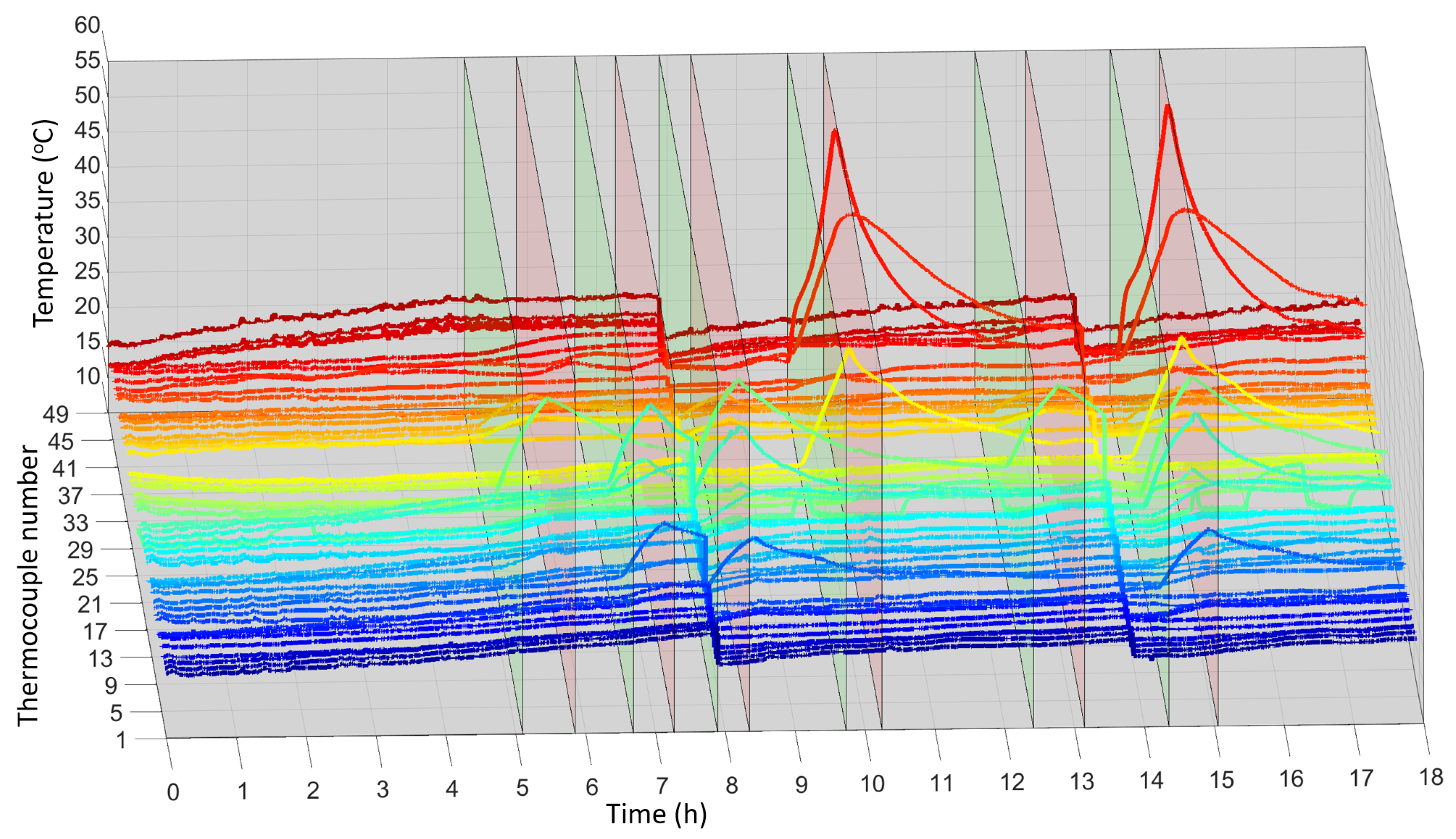
Similarly, Figure 6 shows measurements from the 49 thermocouples using the same time scale. The figure clearly illustrates that most thermocouples follow ambient temperature trends (thermocouples 47, 48, and 49), albeit with lower amplitude and slight time delay due to the thermal inertia of the structure, which has a mass of approximately 30,000 kg. In relation to this figure and the ambient temperature measurements, it should be indicated that the ambient temperature during testing ranged from 17.6 °C to 26.3 °C.
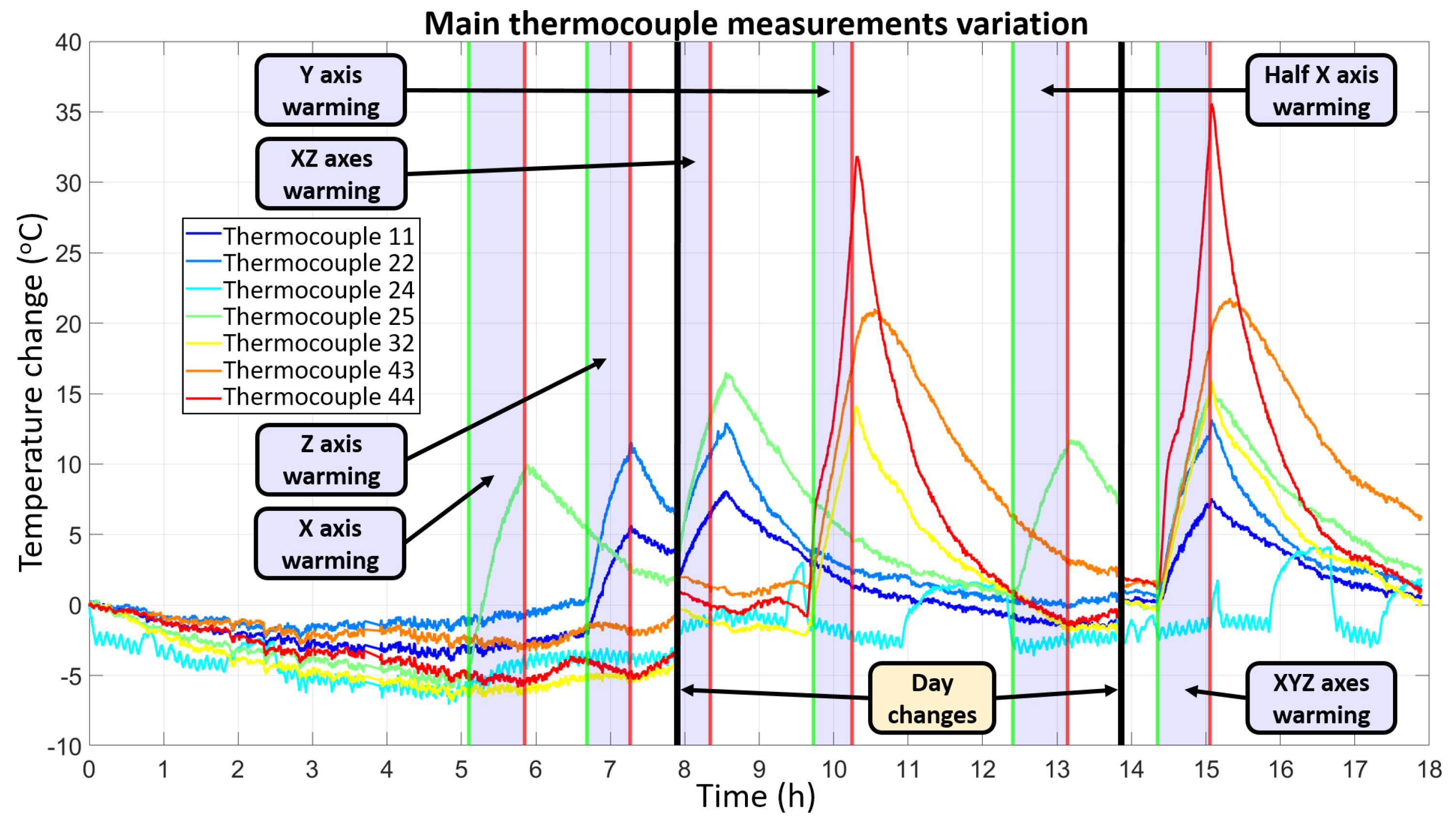
Given that few thermocouples are significantly affected by heating cycles, Figure 7 presents only the seven thermocouples that experienced temperature variations greater than 10 °C. The figure shows that temperature variations between days are generally small with the exception of those thermocouples directly affected by heating cycles near the end of the day. However, despite these small temperature differences, significant deformations can be observed in Figure 4. This indicates that due to the large size of the components, even minor ambient temperature variations can cause significant structural expansion. This has a direct effect on machine accuracy, as very small ambient temperature deviations which may happen even in air-conditioned workshops can lead to important machine deformations.
To better visualise the data presented in Figure 4, Figure 6 and Figure 7, Figure 8 illustrates the deformation measured by IDS bars for each heating cycle individually, while Figure 9 shows the temperature variations for thermocouples exhibiting changes above 1 °C during the corresponding tests. In Figure 8, some bars display noisy signals; these are not caused by cooling but rather by component inertia during movements. Unlike thermocouples, IDS bars measure component deformations due to both thermal and mechanical effects; nevertheless, global trends represent primarily thermal behaviour, making them an adequate type of sensor for this analysis.
According to Figure 8, the machine components experiencing the largest strain during heating cycles are the bed (bars 5, 8, and 9) and column (bars 1, 2, 3, and 4). Because the analysis is based on strain rather than absolute deformation, this result is independent of component dimensions; however, as the components in question are longer than other components, their effect on positioning errors is even larger. Additionally, the component of deformation due to continuous ambient temperature variations has been eliminated from the analysis, leaving only deformation caused during test periods.
The bed deformation arises because the bed supports the guides, bearings, and ball screws of the X and Y axes as well as the Y-axis motor. However, the deformation of the column, resulting from heating cycles in both the X and Z axes, is even greater. In the Z axis, the guides and drive system are mounted directly on the column, while in the X axis both the motor and nut are attached to the column, leading to significant expansion. Conversely, deformation of the bed due to X-axis movements is considerably lower than that caused by Y-axis movements.
Figure 9 shows that heating of the axes is highly localised, primarily affecting areas near the motors, bearings, and ball screw nuts. Contrary to expectations of significant heating in the guides, it is primarily the ball screw nuts and especially the bearings that experience the greatest temperature increases, exceeding even the motors. For the X axis, which has a stationary screw, the nut heats up the most (about 14 °C increase), while for the Y and Z axes, which both have rotating screws, the heat is concentrated in the bearings, reaching up to 55 °C. Thus, without cooling, stationary screws with rotating nuts are preferable for future designs.
A key observation for future thermal error compensation models is that the temperatures and deformations recorded during combined movement of the axes can be approximated as the superposition of the effects from independent axis movements. This result is converse to the consideration in J. Mayr, et al. [2]. Furthermore, the repeatability of thermal effects is very high, yielding nearly identical measurements when repeating heating cycles.
It is noteworthy that despite having identified substantial thermal deformations reaching 100 μ m in the X direction, 170 μ m in the Y direction, and nearly 150 μ m in the Z direction, the resulting machined parts do not exhibit significant errors. This is largely because both machine and workpiece undergo similar thermal expansion due to ambient temperature. Additionally, the global geometry of the machine structure compensates for the deformations of some components with those of other components. Thus, assessing actual part errors is not straightforward; the most reliable method involves tests against calibrated metrological artefacts, external measurement systems, or other techniques, as reviewed by W. Gao et al. [28].
In this study, it was seen that for a common ambient temperature variation during testing (8.7 °C), the effect of ambient temperature on main component deformations was higher than that of internal heat sources, although moving elements consistently reached temperature increases of 15 to 25 °C. In fact, total deformation due to the bed and column reached about 250 μ m, of which 150 μ m (or 60%) was due to ambient effects. This leads to the clear implication that ambient temperature change-induced deformations were larger than those due to internal heat sources even with much smaller variation amplitudes, which means that the effect of ambient temperature per unit temperature change is notably larger than any other heat source. Sensitivity values of about 17.2 μ m/°C due to ambient temperature were obtained, against a mean value of 5.9 μ m/°C for internal heating, meaning that minimizing ambient effects will be more effective in future designs than reducing internal heating effects.
Analysis of the collected data also revealed that thermocouples mounted at the IDS supports were strongly correlated with IDS measurements (>90% in all cases, and >95% for over 70% of sensors). This is a significant finding suggesting that accurate thermal error compensation models could be developed without IDS sensors, which are substantially more expensive than thermocouples.

3.2. Heating of Axis Drives

One of the main heat sources in a machine tool consists of its axis drives. This group of components includes not only the motors generating motion but also the entire transmission and guiding system of the axes, such as guides, ball screws, and bearings.
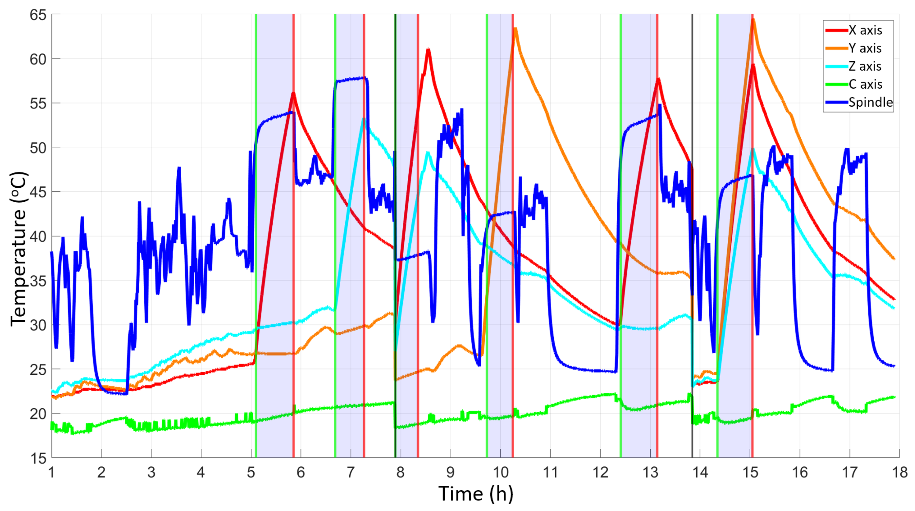
The primary results regarding the influence of the drives have already been discussed in terms of structural deformation in Section 3.1. However, in addition to the thermocouple and IDS sensor measurements, motor temperatures during tests were recorded using their internal sensors. These measurements are summarised in Figure 10, where the A-axis motor is not included because it lacks an internal temperature sensor. While the motor temperatures are consistent with those measured by nearby thermocouples, using motor temperature signals directly in future research would reduce the need to install additional thermocouples, as these signals exhibit higher amplitude and less noise.
From Figure 10, it might be inferred that the spindle was rotating during some axis heating cycles. This was not the case, as the spindle remained stationary at all times; however, its temperature increased rapidly due to its position control, which consumes power even without spindle rotation. Thus, although the spindle might not initially appear as a significant heat source, it actually contributed substantially.
Figure 10 also clearly indicates that after the axis movements ceased, the spindle cooled rapidly. This rapid cooling results from the internal cooling system, complicating potential deformation studies of the spindle. Tests involving heating of the main spindle and the C-axis at turning speeds demonstrated very rapid heating and cooling kinetics, making deformation analysis more complicated. However, due to the cooling system, the impact of these components on the rest of the machine structure was seen to be negligible, despite their high power consumption. Even the headstock, which is in direct contact with the main spindle, was not significantly affected by the spindle heat generation. This is in contrast to the results shown by J. F. Zhang et al. [29], where the spindle affected the machine head due to the absence of an internal cooling circuit. It should be noted that in practice maintaining spindles (both milling and turning) in rotation does influence the machine structure, as it increases the air temperature within the work volume, producing structural deformations similar to the effect of ambient temperature variations. To avoid this, a good design practice would be to control the working volume temperature in order to keep it equal to the ambient temperature in the workshop. During this research, the inside of the machine reached up to 5 °C higher temperature than the environment.
Finally, regarding motor temperatures, as indicated in Section 3.1, it was observed that when either the spindle or the C-axis motor underwent heating compensated by the cooling system, their shared cooling circuit caused slight temperature variations in the other motor. Nevertheless, this effect on structural deformation was again negligible.
Considering these findings, and due to the rapid temperature evolution in the spindle and rotary table, it is advisable for accurate machining to pre-heat the spindle (or rotary table during turning operations) under operating conditions a few minutes before machining starts, maintaining the rotation until the operation is finished without stopping it. This approach prevents significant spindle deformation during machining, ensuring process accuracy due to its minimal structural impact. Other authors, e.g., J. Sun et al. [30], have also pointed out the importance of adequate preheating of the spindle to improve machine accuracy.
Because most deformation arises from ambient temperature variation, improved workshop temperature control would enhance machine accuracy significantly (for this study, the workshop was not climate-controlled, resulting in considerable temperature fluctuations). Aside from environmental factors, the axis drive system is confirmed as the main deformation source, with localised heating leading to substantial positioning errors. Therefore, it would be beneficial to extend the existing cooling system—which currently only cools three motors—to include all drive motors, ball screw bearings, and guides. This solution would be considerably less costly compared to fully cooling the entire structure, a strategy commonly employed in smaller high-precision machines [31], but would lead to a substantial increase in accuracy. In fact, the manufacturer of this machining centre has already adopted this enhanced cooling approach in newer machine versions, with successful results.

3.3. Deformations Due to Cooling System

When performing thermal study of a machine tool, it is crucial to consider heat sources such as motors and ambient conditions; however, localised and potentially significant cooling effects must also be taken into account. Within this category, the most influential factor is the cooling system, which can be divided into two main groups: internal motor cooling and the use of cutting fluids during machining. As pointed out by J. Mayr et al. [32], the influence of cutting fluid is significant; however, it is not studied here, as the work was carried out under conditions equivalent to dry machining or minimal-quantity lubrication (MQL). On the other hand, the effect of the internal cooling of the motors (main spindle and A and C axes) was analysed, confirming its significant impact on the measured temperatures and deformations of certain components.
Due to the on–off cycles of the cooling unit, which keeps the spindle and rotary table temperatures within predetermined limits, cyclical variation in some thermocouple and IDS bar measurements was observed. This effect was especially evident in thermocouple 24, which despite being located far from the table, spindle, or A axis showed temperature oscillations of approximately 1 °C in amplitude and a period of around 5 min during tests. This was seen to be a consequence of having a cooling system duct near this area, which shows the importance of guiding these tubes through the structure during the design stage to avoid direct contact. Without executing any heating cycle, these oscillations have greater amplitude and shorter period due to the reduced heat generation in the motors.
A similar cyclical effect was detected in measurements from bars 1, 2, 4, 8, and 9, as well as to a lesser extent in bars 3 and 5. Although negligible compared to other deformation sources, these cooling cycles not only influence local temperatures but also introduce deformations in machine bed and column structures. Bars 6 and 11 also showed the cooling effect due to their proximity to the cooled C axis motor.
Given these results, although deformations caused by this phenomenon are smaller compared to environmental effects, several alternative solutions can be employed to mitigate them:
  • Modifying cooling system operation: Implementing continuous control instead of cyclic on–off operation would prevent these deformations, thereby stabilising temperatures.
  • Preventing contact between cooling pipes and the structure: This is not always feasible due to movements of the structural components.
  • Using the cooling system to maintain more components at stable temperatures: The additional introduced deformations would be outweighed by the elimination of heating effects.
The first and third solutions have already been adopted by the manufacturer in newer machine models which have replaced the one used in this study, resulting in substantial improvements.

4. Study Limitations and Further Research

During this research, several limitations were encountered:
  • Ambient conditions were not controlled and test times were limited to short periods of time, making difficult to obtain valuable results in terms of ambient temperature effect. However, the goal of the research was to identify the effect of each axis movement on the deformation of different machine structural components, which could be successfully accomplished.
  • The performed tests were limited to some internal heating conditions that can help to understand the deformation of each component; however, compensation model development would require more testing, and this research was mainly focused on improving design decisions.
  • Certain heat sources and sinks were not studied in detail, such as movements of the rotary axes and main spindle, heat induced by machining operations, and the use of cutting fluid.
Even with the aforementioned limitations, this study was able to extract some useful results and conclusions towards more thermally stable machine design.
To avoid existing limitations and continue in the line of reducing machine tool thermal errors, future research should be focused on expanding these results in four main ways:
  • Including a deeper analysis of the effect of rotary axes (A and C) and the main spindle
  • Studying the effect of ambient temperature changes without internal heat generation and using a much longer test time (i.e., a whole year), as these changes were seen to have significant impact on machine deformations
  • Using the results of this work to refine the design of large-scale machine tools, mainly focusing on the improvement of refrigeration systems
  • Studying the effect of long-term wear or material property changes on thermal behaviour as well as the effect of other deformation sources (dynamic effects, cutting forces, etc.) on positioning errors
As future research may benefit from the generated dataset for deeper and more advanced analyses, raw data of this work was published the 30 July 2025, and is available at https://doi.org/10.5281/zenodo.16579803. This includes the full dataset corresponding to all tests performed for this research, including thermocouple and IDS measurements together with internal CNC variables such as axis drives temperature and power as well as the measured positions of encoders and optical scales. This dataset may be especially interesting in the current research environment, as it combines commonly used thermocouple readings with more unusual integral deformation sensor measurements, both of which are adequately synchronized in time.

5. Conclusions

The main conclusions drawn from this research are summarised below:
  • Ambient temperature variations are the primary source of thermal deformations in large-scale machine tools. About 60 % of deformation in the performed tests was due to ambient temperature changes, where ambient temperature varied 8.7 °C, significantly less than the 35 °C due to internal heat sources.
  • The thermal effects of axis drives on machine structure are localised, but lead to significant deformations up to about 100 μ m, predominately in the Y and Z directions.
  • The axis drives primarily generate heat in the ball screw bearings and nuts rather than in the guides or other components. In the performed tests, these components reached temperature increases of 15 to 35 °C.
  • The greatest thermal deformations occurred in the machine bed and column, reaching over 100 μ m in the X direction and 170 μ m in the Y direction for the bed and nearly 150 μ m in the Z direction for the column.
  • The direct influence of heating by the refrigerated motors (particularly milling or turning spindles) on structural component deformation was minimal. The sensors closest to the spindles showed temperature increases under 1 °C, and the most affected IDS bars detected deformations well under 5 μ m.
  • Proper cooling significantly improves machine performance.
  • Cooling the ball screw bearings and axis drive motors could substantially enhance thermal performance.
  • The results of this research can be easily applied in industrial contexts thanks to our close collaboration with machine tool manufacturers during the course of this research.

Author Contributions

Á.S.d.l.M.G.: conceptualization, formal analysis, investigation, methodology, software, validation, visualization, writing—original draft, writing—review and editing. L.S.P.: conceptualization, data curation, investigation, project administration, software, writing—review and editing. L.N.L.d.L.M.: funding acquisition, resources, supervision. All authors have read and agreed to the published version of the manuscript.

Funding

Financial support was received from the Industrial Technology Development Centre (CDTI), an entity of the Spanish Ministry of Science and Innovation, through the MHAYA project (REF. MIG-20221059). Part of the analysis was funded by the Basque Government through support provided to university research groups (IT1573-22) and the ECOVERSO project (KK-2024/00095) funded by the Collaborative Research Grant Programme in Strategic Areas—Elkartek Programme.

Data Availability Statement

The full dataset generated during this research was published the 30 July 2025 and is available for download at https://doi.org/10.5281/zenodo.16579803. In this file, all temperature and deformation measurements can be found together with other internal machine variables such as axis and spindle motor power consumption, encoder positions, motor internal temperature, etc.

Acknowledgments

The authors would like to acknowledge the assistance provided by Francisco Javier Amigo Fuertes from CFAA during the experimental testing.

Conflicts of Interest

The authors declare no conflicts of interest; the funders had no role in the design of the study, in the collection, analysis, or interpretation of data, in the writing of the manuscript, or in the decision to publish the results.

References

  1. Kaulagi, M.N.; Sonawane, H.A. Thermal network-based compensation model for a vertical machining center subjected to ambient temperature fluctuations. Int. J. Adv. Manuf. Technol. 2023, 124, 3973–3994. [Google Scholar] [CrossRef]
  2. Mayr, J.; Jedrzejewski, J.; Uhlmann, E.; Donmez, M.A.; Knapp, W.; Härtig, F.; Wendt, K.; Moriwaki, T.; Shore, P.; Schmitt, R.; et al. Thermal issues in machine tools. Cirp Ann. 2012, 61, 771–791. [Google Scholar] [CrossRef]
  3. Li, Y.; Yu, M.; Bai, Y.; Hou, Z.; Wu, W. A review of thermal error modeling methods for machine tools. Appl. Sci. 2021, 11, 5216. [Google Scholar] [CrossRef]
  4. Li, Q.; Li, H. A general method for thermal error measurement and modeling in CNC machine tools’ spindle. Int. J. Adv. Manuf. Technol. 2019, 103, 2739–2749. [Google Scholar] [CrossRef]
  5. Liu, J.; Ma, C.; Wang, S. Data-driven thermally-induced error compensation method of high-speed and precision five-axis machine tools. Mech. Syst. Signal Process. 2020, 138, 106538. [Google Scholar] [CrossRef]
  6. Yin, Q.; Tan, F.; Chen, H.; Yin, G. Spindle thermal error modeling based on selective ensemble BP neural networks. Int. J. Adv. Manuf. Technol. 2019, 101, 1699–1713. [Google Scholar] [CrossRef]
  7. Yau, H.T.; Kuo, P.H.; Chen, S.C.; Lai, P.Y. Transfer-Learning-Based Long Short-Term Memory Model for Machine Tool Spindle Thermal Displacement Compensation. IEEE Sens. J. 2023, 24, 132–143. [Google Scholar] [CrossRef]
  8. Iñigo, B.; Colinas-Armijo, N.; López de Lacalle, L.N.; Aguirre, G. Digital twin for volumetric thermal error compensation of large machine tools. Sensors 2024, 24, 6196. [Google Scholar] [CrossRef]
  9. Sáinz de la Maza García, A.; Sastoque Pinila, L.; López de Lacalle Marcaide, L.N. Thermally induced volumetric error modelling on large-scale machining centre. In Proceedings of the 4th International Conference on Thermal Issues in Machine Tools (ICTIMT2025), Zurich, Switzerland, 17–19 June 2025; Lecture Notes in Production Engineering . Springer: Cham, Switzerland, 2025. in press. [Google Scholar]
  10. Sáinz de la Maza García, A.; Sastoque Pinilla, L.; Amigo Fuertes, F.J.; Villarrazo Rubia, N.; Iñigo, B.; López de Lacalle Marcaide, L.N. Measuring thermally induced volumetric error of large-scale machining centre. In Proceedings of the XI Manufacturing Engineering Society International Conference (MESIC 2025), Bilbao, Spain, 18–20 June 2025. [Google Scholar]
  11. Ess, M. Simulation and Compensation of Thermal Errors of Machine Tools. Ph.D. Dissertation, ETH Zürich, Zürich, Switzerland, 2012. [Google Scholar]
  12. Ye, W.H.; Guo, Y.X.; Zhou, H.F.; Liang, R.J.; Chen, W.F. Thermal error regression modeling of the real-time deformation coefficient of the moving shaft of a gantry milling machine. Adv. Manuf. 2020, 8, 119–132. [Google Scholar] [CrossRef]
  13. Weng, L.; Gao, W.; Zhang, D.; Huang, T.; Liu, T.; Li, W.; Zheng, Y.; Shi, K.; Chang, W. Analytical modelling method for thermal balancing design of machine tool structural components. Int. J. Mach. Tools Manuf. 2021, 164, 103715. [Google Scholar] [CrossRef]
  14. Chu, W.L. Integrating machine learning and feature analysis for predicting and managing thermal deformation in machine tools. Case Stud. Therm. Eng. 2024, 57, 104343. [Google Scholar] [CrossRef]
  15. Winiarski, Z.; Jedrzejewski, J.; Kwaśny, W.; Ha, H. Reduction of precise machining centre column thermal deformations caused by changes in ambient temperature by means of liquid cooling. J. Manuf. Processes 2024, 110, 192–201. [Google Scholar] [CrossRef]
  16. Liu, P.; Yao, X.; Ge, G.; Du, Z.; Feng, X.; Yang, J. A Dynamic Linearization Modeling of Thermally Induced Error Based on Data-Driven Control for CNC Machine Tools. Int. J. Precis. Eng. Manuf. 2021, 22, 241–258. [Google Scholar] [CrossRef]
  17. Zheng, Y.; Fu, G.; Mu, S.; Lu, C.; Wang, X.; Wang, T. Thermal Error Transfer Prediction Modeling of Machine Tool Spindle with Self-Attention Mechanism-Based Feature Fusion. Machines 2024, 12, 728. [Google Scholar] [CrossRef]
  18. Chen, P.H.; Chang, P.Z.; Hu, Y.C.; Luo, T.L.; Tsai, C.Y.; Li, W.C. On the robustness and generalization of thermal error models for CNC machine tools. Int. J. Adv. Manuf. Technol. 2024, 130, 1635–1651. [Google Scholar] [CrossRef]
  19. Abdulshahed, A.M.; Longstaff, A.P.; Fletcher, S.; Myers, A. Thermal error modelling of machine tools based on ANFIS with fuzzy c-means clustering using a thermal imaging camera. Appl. Math. Model. 2015, 39, 1837–1852. [Google Scholar] [CrossRef]
  20. Chiang, M.; Zhang, T. Fog and IoT: An overview of research opportunities. IEEE Internet Things J. 2016, 3, 854–864. [Google Scholar] [CrossRef]
  21. Brecher, C.; Klatte, M.; Lee, T.H.; Tzanetos, F. Metrological analysis of a mechatronic system based on novel deformation sensors for thermal issues in machine tools. Procedia CIRP 2018, 77, 517–520. [Google Scholar] [CrossRef]
  22. Baum, C.; Brecher, C.; Klatte, M.; Lee, T.H.; Tzanetos, F. Thermally induced volumetric error compensation by means of integral deformation sensors. Procedia CIRP 2018, 72, 1148–1153. [Google Scholar] [CrossRef]
  23. Naumann, C.; Naumann, A.; Bertaggia, N.; Geist, A.; Glänzel, J.; Herzog, R.; Zontar, D.; Brecher, C.; Dix, M. Hybrid thermal error compensation combining integrated deformation sensor and regression analysis based models for complex machine tool designs. In International Conference on Thermal Issues in Machine Tools; Lecture Notes in Production Engineering; Springer: Cham, Switzerland, 2023; pp. 28–40. [Google Scholar] [CrossRef]
  24. Tapia, E.; Lopez-Novoa, U.; Sastoque-Pinilla, L.; López-de-Lacalle, L.N. Implementation of a scalable platform for real-time monitoring of machine tools. Comput. Ind. 2024, 155, 104065. [Google Scholar] [CrossRef]
  25. Gebhardt, M.; Wegener, K. Temperatureinfluss auf Werkzeugmaschinen. Maschinenbau 2013, 42, 59–63. [Google Scholar] [CrossRef]
  26. Shabi, L.; Weber, J.; Weber, J. Investigation of the Potential of Different Cooling System Structures for Machine Tools. In Fluid Power Networks: Proceedings: 19th–21th March 2018: 11th International Fluid Power Conference; Aachen, Germany, 19–21 March 2018, RWTH Aachen University: Aachen, Germany, 2018; Volume 1, pp. 82–95. [Google Scholar] [CrossRef]
  27. Liu, T.; Gao, W.; Tian, Y.; Zhang, H.; Chang, W.; Mao, K.; Zhang, D. A differentiated multi-loops bath recirculation system for precision machine tools. Appl. Therm. Eng. 2015, 76, 54–63. [Google Scholar] [CrossRef]
  28. Gao, W.; Ibaraki, S.; Donmez, M.A.; Kono, D.; Mayer, J.R.R.; Chen, Y.L.; Szipka, K.; Archenti, A.; Linares, J.M.; Suzuki, N. Machine tool calibration: Measurement, modeling, and compensation of machine tool errors. Int. J. Mach. Tools Manuf. 2023, 187, 104017. [Google Scholar] [CrossRef]
  29. Zhang, J.F.; Feng, P.F.; Wu, Z.J.; Yu, D.W.; Chen, C. Thermal structure design and analysis of a machine tool headstock. Mechanika 2013, 19, 478–485. [Google Scholar] [CrossRef]
  30. Sun, J.; Liu, Z.; Qiu, C.; Luo, J.; He, L.; Liu, H.; Sa, G.; Jiang, Z.; Tan, J. Machining accuracy prediction and adaptive compensation method of CNC machine tool under absence of machining process sensing. J. Intell. Manuf. 2025, 36, 3923–3940. [Google Scholar] [CrossRef]
  31. Mareš, M.; Horejš, O.; Fiala, Š.; Havlik, L.; Stříteský, P. Effects of cooling systems on the thermal behaviour of machine tools and thermal error models. J. Mach. Eng. 2020, 20, 5–27. [Google Scholar] [CrossRef]
  32. Mayr, J.; Gebhardt, M.; Massow, B.B.; Weikert, S.; Wegener, K. Cutting fluid influence on thermal behavior of 5-axis machine tools. Procedia CIRP 2014, 14, 395–400. [Google Scholar] [CrossRef]
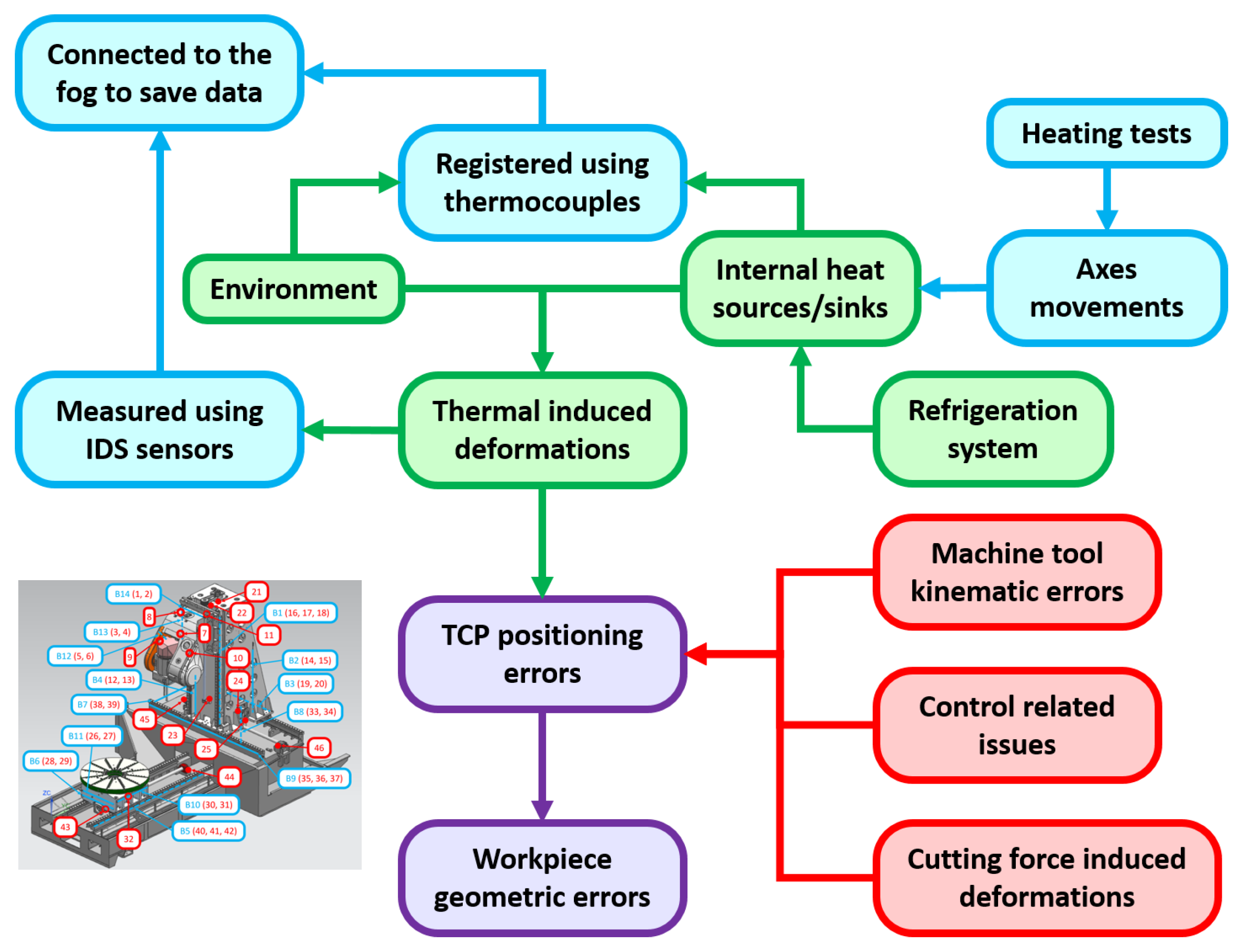
Figure 1. Mind map showing the relationship between the different thermal-related effects affecting machine tools and the measuring system used in this research. In red: error sources not considered in this research; in green: concepts related to thermal error; in blue: sensors used in this research and effects of the performed tests; in purple: machine tool errors.
Jmmp 09 00267 g001
Figure 2. Linear (X, Y and Z) and rotary axes (A and C) of the machining centre.
Jmmp 09 00267 g002
Figure 3. Placement of thermocouples (red) and IDS bars (blue). Empty circles and dashed lines indicate hidden sensors. Thermocouples associated with bars are installed at their supports.
Jmmp 09 00267 g003
Figure 4. Deformations measured by IDS bars during tests. Green vertical lines indicate test start times, while red lines indicate test end times.
Jmmp 09 00267 g004
Figure 5. Deformation shape after each heating cycle. Red indicates large, orange medium and green small deformations.
Jmmp 09 00267 g005
Figure 6. Temperature measurements; green planes mark test start times, while red planes indicate test end times.
Jmmp 09 00267 g006
Figure 7. Variation in the most representative thermocouple measurements (maximum amplitude greater than 10 °C) during thermal tests.
Jmmp 09 00267 g007
Figure 8. Unit deformation measured by IDS sensors during each test.
Jmmp 09 00267 g008
Figure 9. Temperature measurements from the most representative thermocouples (those varying by more than 1 °C) during each test.
Jmmp 09 00267 g009
Figure 10. Motor temperatures during heating tests.
Jmmp 09 00267 g010
Table 1. Summary of test characteristics.
Heat TestLinear Speed (m/min)Rotation Speed (rpm)Range
X Y Z A C Spindle
X axis3000000Full
Y axis0250000Full
Z axis0030000Full
XZ axes30030000Full
XYZ axes302530000Full
Half X axis3000000Last half
Table 2. Starting and ending times of measurements on each testing day (local time, GMT+1).
DayStarting TimeEnding TimeDuration
6 November 20247:5915:527:53
7 November 20247:5413:525:58
8 November 20247:4611:494:03
Disclaimer/Publisher’s Note: The statements, opinions and data contained in all publications are solely those of the individual author(s) and contributor(s) and not of MDPI and/or the editor(s). MDPI and/or the editor(s) disclaim responsibility for any injury to people or property resulting from any ideas, methods, instructions or products referred to in the content.