Article

Experimental Study on the Electromagnetic Forming Behavior of Pre-Painted Al 99.0 Sheet

1
Faculty of Materials Science and Engineering, Technical University of Iasi, 700050 Iasi, Romania
2
Micronetics Ltd., 014336 Bucuresti, Romania
3
Help Flux Ltd., 700483 Iasi, Romania
*
Author to whom correspondence should be addressed.
J. Manuf. Mater. Process. 2025, 9(8), 259; https://doi.org/10.3390/jmmp9080259
Submission received: 9 June 2025 / Revised: 16 July 2025 / Accepted: 24 July 2025 / Published: 3 August 2025

Abstract

Development of forming methods for surface-coated metals is a current concern due to their economic and environmental advantages. For a successful forming operation, it is necessary that both components, the substrate and the coating, are able to withstand stress without damage until the final shape and dimensions are reached. This goal can be achieved through good knowledge of the elastic and plastic properties of the substrate and the coating, the compatibility between them, the appropriate surface treatment, and the rigorous control of technological forming parameters. Our study was carried out with flat specimens of pre-painted Al 99.0 sheet that were electromagnetically formed by bulging. Forming behavior was investigated as depending on the initial thickness of the substrate, on the aluminum sheet pretreatment, as well as on the plastic deformation path of the metal–paint structure. To verify the damage to the paint layer, tests with increasing strains were performed, and the interface between the metal and the coating layer was investigated by scanning electron microscopy. The obtained results indicate that electromagnetic forming of pre-painted sheets can be a feasible method for specific applications if the forming degree of the substrate is tightly correlated with the type of desired coating and with the pretreatment method used for the metal surface.

1. Introduction

The global production of metal sheet parts is impressive in its extent and serves all economic sectors, including the aerospace industry, construction machinery, agriculture, means of transportation, medical apparatuses, etc. The digital era, started by Industry 4.0 in all manufacturing processes, brings new challenges in terms of dimensional accuracy and product quality, productivity, and the environment [1]. An important category of industrial applications is related to the processing of metal sheets coated with different protective layers, through which different parts are obtained, such as those manufactured by plastic deformation (deep drawing, bending, embossing, etc.). A modern procedure for manufacturing metal sheet parts that is economically effective, highly accurate and environmentally friendly is electromagnetic forming (EMF). The main difference between EMF and conventional forming methods is the contact-free application of force [2]. The lack of contact between a moving tool and a workpiece gives EMF a major advantage for manufacturing net shape parts that do not require subsequent finishing or coating operations. Beckschwarte et al. [3] emphasized the advantage of contact-free application of the forming force in their paper, in which the embossing of optical and functional microstructures was carried out, and the application of EMF in the replication of structures with retroreflective and tribological properties was demonstrated.
Coating metal surfaces with thin layers of all kinds (paint, deposited metal layers, sputtered thin films, etc.) is performed for decorative purposes, for providing corrosion protection, or for improving surface properties. The required properties of coating materials include mechanical (scratch resistance, toughness, and flexibility), chemical (resistance to substances) and thermal (stability at high temperatures) properties. Coatings can be applied to metal surfaces, either before or after plastic deformation, depending on the forming method applied [4].
The importance of the coating-forming problem for industry is demonstrated by some published articles analyzing what happens to certain metals coated with paints and then plastically deformed by various methods (biaxial stretching, uniaxial tension, bending, etc.), but not by the EMF method. The EMF process is characterized by high-speed forming, with the values indicated in the specialized literature being between 100 m/s and 300 m/s: typically exceeding 100 m/s [5], commonly 200 m/s [6] and reaching up to 300 m/s [7]. These high forming speed values lead to a productivity of about 600 parts/h, i.e., 10 parts/min. Subsequent painting of these parts electromagnetically formed, piece by piece, becomes economically inefficient in relation to the high productivity achieved during forming and the high paint losses.
Another problem, especially present in classic pressing methods, is that after pressing, metal sheet parts have traces of lubricants on their surfaces that must be removed through cleaning operations with various solvents, which incurs related costs, including environmental ones. These disadvantages can be eliminated by cutting (stamping) the workpieces from an already painted sheet of metal and performing EMF. Therefore, the application of the coating to flat-sheet metal workpieces has economic, technological and ecological advantages [8]. Only a few papers include general references to the possibility of deformation by EMF of coated metal parts [9,10]. Thomas and Triantafyllidis [11] present a study on EMF of coated tubes, but they do not focus on the behavior of the coating during high-speed forming.
These aspects motivated the onset of the experimental research, the results of which are presented in this paper.
The research conducted by Liu and Chen [12] aimed to investigate the deformation mechanism and failure-tolerant characteristics of laminated polymer-coated metal sheets under different loading conditions. The authors determined that under dynamic incremental deformation loads, the failure modes included single-layer fracture, double-layer fracture, delamination and their mixed case. Pre-painted metal sheets provide corrosion protection, so they must resist failures through cracking or delamination during forming. Failure of coatings during forming is due to large deformations, and to understand surface strains, Sorce et al. [13] proposed the application of the T-bend test. The maximum surface stresses during bending were predicted using finite element modeling and then verified experimentally using digital image correlation. Finally, a new analytical model was established to determine the maximum surface stresses. To understand the behavior of a metal sheet coating during forming, Sorce et al. [14] performed Erichsen cupping tests, which provided answers to questions regarding the connections that must exist between the formability, material properties and chemical structure of the polymer for the development of better coatings. A master curve of maximum strain versus indentation depth (Erichsen index) was determined, which allows the determination of the coating’s maximum strain on a metal substrate.
The forming behavior of a Z100 steel sheet coated with a polyester resin was studied by Ciccarelli et al. [15]. They performed interrupted tensile tests at different strain levels, through which the elongation characteristic of both the paint layer and the steel substrate was evaluated. The occurrence of superficial damage on the paint layer was also detected and the pre-painted sheet’s thinning of each layer was evaluated according to the strain levels. The forming behavior of pre-painted steel sheets was also investigated by Forcellese et al. [16]. They added the hemispherical punch test to study the forming behavior of pre-painted sheets under uniaxial and biaxial stretching conditions, respectively. The tests were also performed with interruption to detect the appearance of superficial damage on the paint layer and they highlighted that superficial damages to the paint layer occur earlier in the case of biaxial stretching of the sheet. Muto et al. [17] compared water-based and solvent-based coatings for pre-painted steel sheets, and the results of dynamic mechanical analysis showed that the crosslink density of the entire water-based paint film was higher than that of the solvent-based film. This conclusion will contribute to the improvement of design and performance of water-based pre-painted steel sheets as environmentally friendly alternatives to solvent-based coatings.
Friction plays a major role in forming processes, being a local phenomenon influenced by the contact conditions at the tool–material interface. Friction mainly produces heat and leads to increased energy consumption by increasing the required deformation force. In this regard, researchers are interested in the tribological evaluation of different coating materials and the design of new coating materials that also possess lubricating properties. Friction issues of coated sheets in forming processes have been addressed by Shisode et al. [18]. They developed a multi-scale friction model applicable to coated sheets for boundary lubrication regime, which takes into account the physical behavior of the coating and the measured surface topographies of the sheet and tools. The friction model was validated by different sets of laboratory-scale friction tests and cup drawing experiments on zinc-coated steel sheets.
Dessie and Lukacs [19] examined the impact of thermal cycling applied during painting of steel sheets and concluded that pre-painted steel becomes more susceptible to springback, due to the interaction between material characteristics, processing techniques and forming conditions that lead to the amplification of springback phenomena.
In their paper, Vayeda and Wang [20] present a new method for evaluating the adhesion of coatings made on formed metal sheets, based on the concept of forming limit diagram. The proposed methodology combines the notch-coating adhesion test, the cross-hatch tape test, accelerated conditioning, the uniaxial tensile test, and the rectangular stretch bend test. The experimental results showed that the coating adhesion can be affected by the plastic deformation of the substrate. Barai and Weng [21] have sought the dependence properties of nanocrystalline coatings such as its yield strength, hardness, and wear resistance on the grain size in order to obtain the strongest state of the coating material. The study led to the theoretical model’s development of composite plate, with which can be established the grain size dependence of plastic strength in nanocrystalline coatings. Bouzakis et al. [22] have developed a method that shows the residual stresses after load removal remain into the coating layers of the formed parts. The method is based on the finite element simulation and experimental verification by the nanoindentation test, and this can determine the residual stresses in a coating which undergoes an elastic or plastic deformation. The influence of interface on epoxy-polyester films’ deformation, deposited by electrostatic spraying, was studied by Barletta et al. [23] by applying the micro-scratch test. The influence of the substrate was also studied by scratch tests of films deposited on rigid surfaces and on soft silicon substrates.
Paper [24] presents a new method for carrying out bending tests, where the sample is subjected to the full range of curvatures desired in a single test. The blade shape sample (diamond-like carbon multilayer coating) is gradually pressed on a bending snail and a surface with variable curvature is obtained, which allows the determination of the critical strains where damage appears. The adhesion with polymer coating of metal sheets after applying a stretch plastic deformation was studied by Huang and Wang [25]. The authors have performed a set of experiments for evaluating the strength of the coating before and after uniaxial stretching. A model for predicting the adhesion loss of the coating after plastic deformation has been proposed and validated by comparison with experimental results.
The plastic deformation behavior [26] in the case of polyester series used for cross-linked coatings has been studied as well. Through tensile tests under a range of temperatures and strain rates, the time and temperature dependencies on the mechanical response were investigated and a visco-elastic model based on the stress–strain tensile curve obtained for paint was established. In other applications [27], the ability of nanolayers sputtered to plastic deformation by combining the traditional nanoindentation test with microcompression test was evaluated. The conclusion is that the nanolayers exhibit unique plastic deformation behavior, with a small-scale plasticity transition and a scaling activation behavior of small volume with intrinsic size.
To understand the failure mechanisms and predict the lifetime of the coating layers, it is important to determine the interfacial adhesion energies. Zhu et al. [28] have applied a cohesive zone finite element model and a compression test, by which the interfacial adhesion energy was determined and measured the failure process of buckling, coating spallation and delamination arising from an artificial defect. Another problem of interest is to achieve adhesive bonding of coated high-strength steel for automotive components subjected to impact loadings [29]. Determination of bond strength was made by the usual testing methods (i.e., butt-joint or lap-shear tests) and revealed the following findings. Coatings and paints considerably influence the mechanical strength of adhesive bonding; there is a significant dependence on the nature of the paint; it was observed that the weakest layer in the whole joint is the coating or the paint. Apart from plastic deformation, coated metal sheets can be processed through the stamping operation. Correctly designing a stamping process must prevent defects, such as delamination and tearing [30]. The study was conducted by stamping a polymer-coated metal sheet and development of a defect diagram, which proved to be effective and appropriate for real stamping process design.
A synthesis of the investigations in this field presented above shows that the preferred methods of verifying the coating adhesion are the classics, uniaxial tensile and bending tests. However, these are tests conducted at low speeds of deformation, which does not cover all practical situations, such as the one in which the material is subjected to shock loading. The disadvantage of the other methods for adhesion testing after plastic deformation, i.e., pull-off stress, is that the formed specimen must have a flat surface on which the investigations can be made. The analysis of the studies mentioned above reveals two research directions that converge towards a common goal. On the one hand, metal forming specialists perform different types of tests to elucidate the plastic deformation behavior of metals coated with certain layers and search for the best forming methods that do not destroy the coating. On the other hand, coating researchers await the results of the forming tests in order to analyze the behavior of the coatings and to be able to develop new recipes for coating materials with improved properties. The common question that researchers must answer, regardless of the forming method applied, is as follows: What is the maximum plastic strain of the metal substrate that corresponds to a maximum elastic strain of the coating layer so as not to cause cracking of the coating?
In this study, our focus has shifted to behavior testing under plastic deformation by EMF of some metal sheets with covered surfaces. Regarding the EMF, a shock loading is applied to the material, but contact-free; thus, the test method proposed in the present paper is unique. The paper analyzes what happens with a painted sheet when it is electromagnetically formed.

2. Materials and Methods

2.1. Materials Used and Their Properties

The support material (substrate) was Al 99.0 commercial aluminum, out of which blade samples have been prepared, with dimensions 110 × 45 × 1.0 mm and 110 × 42 × 0.8 mm. The lower sides of the blade specimens were curved with a radius of 55 mm in order to be mounted in the die with 110 mm diameter.
Three types of coatings were tested:
(1)
Specimens simply cleaned (SSCb) and coated by painting in an electrostatic field with powder paint, RAL 9005 code (shiny black). The paint layer had an average thickness of 61.2 µm.
(2)
Specimens simply cleaned (SSCg) and coated by painting in an electrostatic field with powder paint, RAL 7016 code (matte grey). The paint layer had an average thickness of 62.3 µm.
(3)
Specimens degreased and chromatized (SDC) first and then coated in an electrostatic field with powder paint, RAL 7016 code (matte grey). In this case, the paint had an average thickness of 64.9 µm.
For a simple cleaning of specimens from the first and second set, we used white spirit. Degreasing of the substrate was performed with a product specific for aluminum and its alloys. The specimens were immersed in a tank containing the acid solution with a 5% concentration for 5 min at a temperature of 40 °C. Chromatizing was carried out with a liquid product, which was dissolved in water and produced a pale-yellow chrome layer on the aluminum. This layer gives excellent corrosion protection and very good support for subsequent layers of paint (or plastic). The specimens degreased in advance were placed in a bath with pH 2 for 5 min at a temperature of 30 °C. After this, the specimens were washed and dried. This was followed by paint coating the specimens by electrostatic spraying, and then the powder film curing was performed in a convection furnace for 15 min at temperature of 180 °C. The initial thickness of the paint layer was determined by measuring on direction X, every 5 mm, the paint layer to 33% of each set of test specimens, randomly chosen. The original width was determined as the average of measurements for the selected test group.
The rolled sheet of Al 99.0 aluminum (EN AW-1200) is used for workpieces in the processes of cold plastic deformation and has the chemical composition indicated in Table 1. Also, the material density was experimentally determined and has a value of 2701.657 kg/m3.
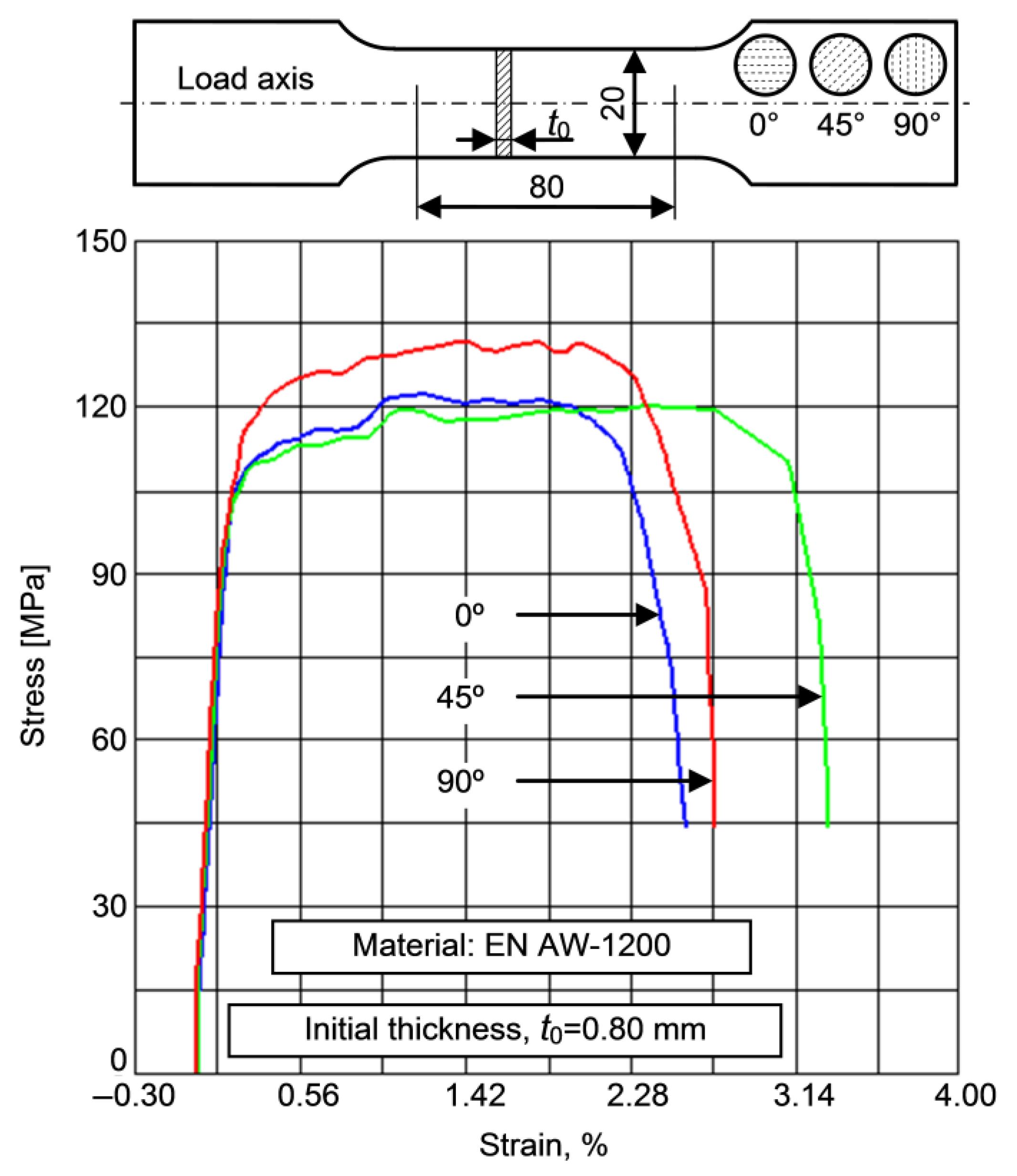
The substrate material has been tensile tested in order to determine its mechanical properties [31]. The specimens prepared for tensile tests were taken to form axis angles of 0°, 45° and 90° with the rolling direction of the metal sheet. Tests were performed at room temperature (20 °C) on a hydraulic machine MTS 810.24 (PartTarget Inc., Northridge, CA, USA) with accuracy class 1 and equipped with data acquisition system. Table 2 provides mechanical properties for substrate material, where E is the Young’s modulus, Rp0.2 is the yield strength, Rm is the ultimate tensile strength and A80 is the elongation at fracture on 80 mm. The registered tensile curves are illustrated in Figure 1.
The coating material has thermo-sensitive powder paint, matte, without hardener, based on saturated polyester resins. These resins confer paint an excellent aging resistance to atmospheric conditions, ultraviolet radiation and saponification. They are supplemented by very good mechanical properties, which lead to coatings with outstanding resistance in the external environment. Powder paint film characteristics from the first set of specimens are given in Table 3. The paint film properties of the third set of test specimens are given in Table 4.
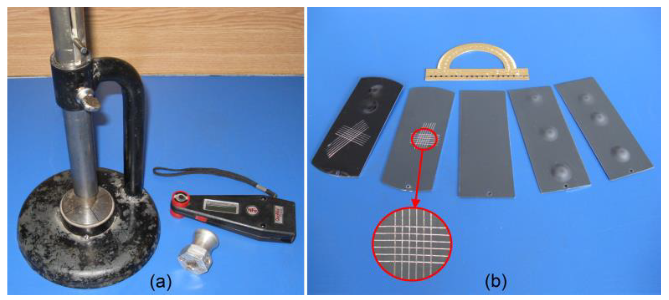
The achieved coating thickness was investigated with a coating thickness measuring device QuaNix 1500 (Automation Dr. Nix GmbH & Co KG, Cologne, Germany), with the resolution of 1 µm in a measuring range of 0–99.9 µm. The measurement procedure is specified in standard [32]. The eddy current gauge was placed on the coating surface to measure the paint thickness and the value was read on the instrument’s display.
Adhesion of the coating layers deposited on the undeformed samples was investigated by scratch test and impact test. For the scratch test, a cross-hatch cutter 6 × 2 was used and the operating procedure specified in [33] was applied. The test consisted of assessing the paint resistance to separation from the substrate when a right-angle lattice pattern is cut into the coating, penetrating up to the substrate.
Impact tests were performed on a standard variable-height impact apparatus, with a ball of 20 mm diameter and a falling weight of 1000 g, under standardized conditions [34]. The conducted work encompassed repeating the procedure of releasing the weight from successively greater heights until cracks were observed, the increments of height being multiples of 25 mm. The maximum height for dropping the weight is 300 mm.
An image of the experimental apparatuses for testing the adhesion of the coating layer before plastic deformation of the metal sheet is shown in Figure 2.

2.2. Tests, Devices and Equipment

The coated specimens were subjected to two types of plastic deformation tests:
(1)
Electromagnetic forming with clamping of the specimens with a plane ring, without blocking the displacement of the material (only for SSCb).
(2)
Electromagnetic forming with clamping of the specimens with a V rib type ring, with blocking of the displacement of material from the edge (for SSCb, SSCg and SDC).
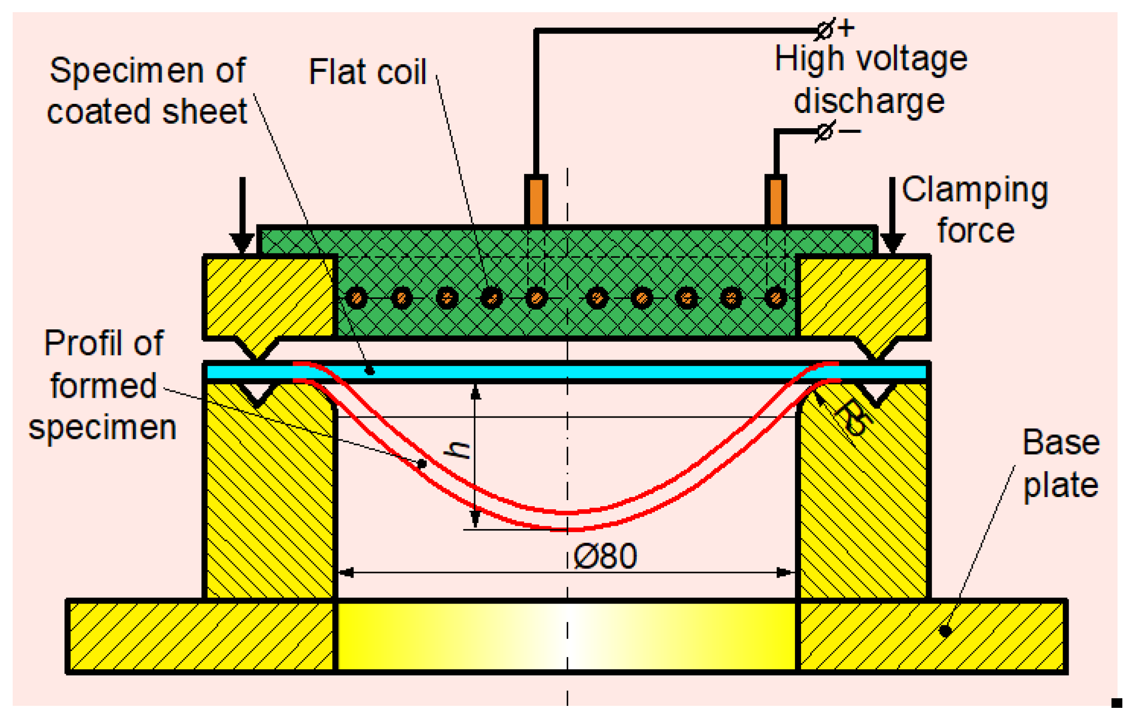
The schematic of tests by EMF (clamping with V rib type ring) is shown in Figure 3.
In both cases, the specimens were freely formed on a ring-type die with an edge radius of 5 mm. Increasing deformation energies were gradually applied until the first cracks were observed on the surface of the coating subjected to maximum elongation.
The tool used for forming the specimens was a flat spiral coil made of copper wire with 5 mm diameter and with an external diameter of 78 mm. The electrical parameters of the coil and the discharge circuit parameters are given in Table 5.
The used EMF machine (ICPE, București, Romania), shown in Figure 4, is provided with four capacitors of 50 µF each, which can be coupled or decoupled in order to obtain different total capacitance values C. The charging voltage V of the capacitors can be set (adjusted) at discrete values by means of an autotransformer.
In these experiments, we used the maximum capacitance C (200 µF) of the EMF machine and modified the charging voltage V to obtain the desired deformation energy.

2.3. Investigation Techniques

The samples’ surface morphology and the metal–paint interface after EMF were evaluated using scanning electron microscopy (SEM). The apparatus used was a Vega II LMH (Tescan Orsay Holding, Brno - Kohoutovice, Czech Republic) microscope with the following technical characteristics: magnification 1,000,000×; secondary electron detector; 30 kV maximum accelerating voltage; high vacuum; software for microscope control and image capturing.
The effect of high-speed plastic deformation on the paint adhesion loss (both SSC and the SDC) was analyzed by SEM. Examination of the samples was performed both on the edge and in cross-section along the profile of the samples already formed. Microscopic investigations have been carried out taking into account the organic nature of the coating layer and the metallic nature of the substrate. Due to the different nature of the two materials, it was necessary that analysis of the changes occurred at the interface, to be performed through an alternative application of 5 and 30 kV voltages, respectively, to filament heating. All the investigations were undertaken in vacuum conditions.

3. Results and Discussion

SSCb (with blocking), with 1.0 mm thickness substrate, were first tested. For this set of tests, different deformation energies were applied, with values between 0.900 and 1.600 kJ. The range of used energies could be finely adjusted by controlling the charging voltage of the capacitor bank, the ability to adjust the EMF machine being at a level of 10 V. Plastically deformed samples were studied under a microscope to detect the occurrence of cracks in the paint layer. After noticing the occurrence of cracks on the coated surface, tests were continued with lower values of applied deformation energy, in order to determine the extent to which the coating layer can be formed elastically (no cracks) together with plastic deformation of the substrate. From the tests carried out, the experiments that led to the achievement of the mentioned purpose (occurrence of cracks in the paint) were retained and the results are noted in Table 6, in the order of execution.
The deformation energy pulse applied to the specimen was calculated with the equation:
E = ( C V 2 ) / 2 ,
where C and V are the capacitance and the charging voltage of the capacitor bank, respectively.
The limit up to which the substrate can be plastically deformed without damaging the coating layer was established considering the elongation of the base material. The elongation was calculated by the equation:
ε = [ ( l 1 l 0 ) / l 0 ] × 100 % ,
where l 1 is the final length after deformation and l 0 is the initial length of the specimen.
The initial length was considered on one of the straight sides of the specimen and the final length was measured on the same side after the application of electromagnetic force. The final (profile) length was measured with MarVision MM 320 (Aerospace Manufacturing and Design, Valley View, OH, USA) video measuring microscope using automatic edge detection, a feature provided by its software. This device has a resolution of 1 µm and a maximum permissible indication error (MPE E X/Y) of 1.9 µm.
Further, the SSCb set (without blocking) was electromagnetically formed. This time the substrate was formed more than the first set for the same amount of energy applied. The elongation obtained and observations relating to the occurrence of cracks in the paint layer are shown in Table 7.
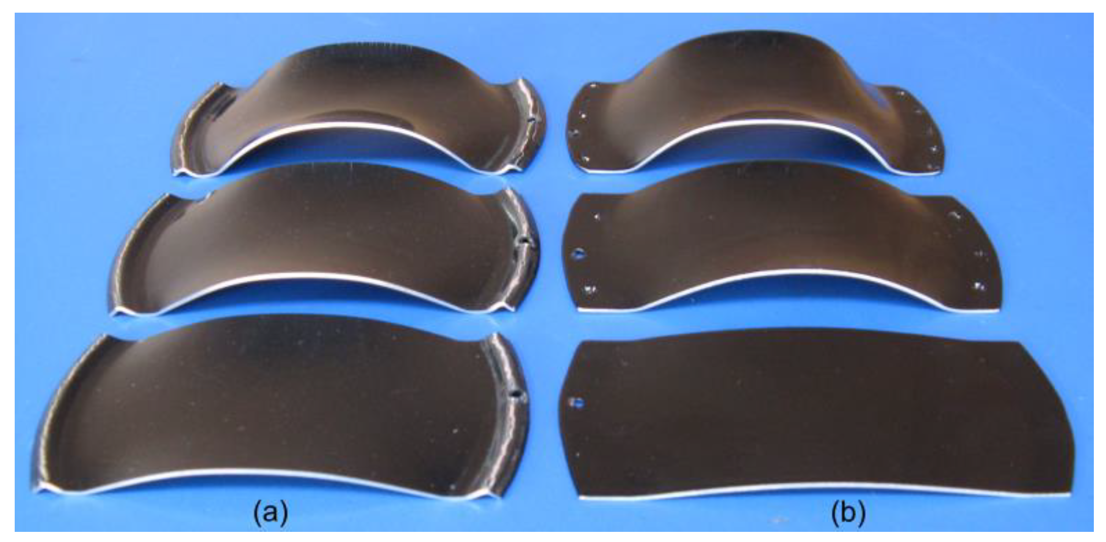
Some of the electromagnetically formed SSCb by the two plastic deformation paths are shown in Figure 5.
The range of energies applied to the second set of specimens was between 0.400 and 1.600 kJ. A comparative image regarding the influence of plastic deformation for the same type of interface (Al 99.00-polyester powder film) on the occurrence of cracks in the coating layer is shown in Figure 6.
After the EMF tests, the obtained samples were examined by SEM. The SEM images show the paint layer status for various strains of the substrate (Al 99.0) obtained by EMF. SEM analysis performed on the coating layer–metal sheet interface is presented in a few images in Figure 7.
The SEM images show that cracks, developed after EMF, are defined as “surface cracking”. These cracks were laterally propagated through the paint layer in a channeling process due to high tensile stresses. This mode of damage is encountered in coatings with high residual stress and crack propagation on the surface of the formed sample due to the relaxation of elastic strain energy stored in the coating thickness. These processes occur because the energy with which the paint is formed exceeds the adhesion energy limit between the paint layer and the aluminum substrate.
The next set of tests was carried out with SCD. The working procedure and the method of detecting the appearance of cracks were similar to those applied in the two previous sets. Results chosen for presentation are given in Table 8.
In the last set of tests, EMF at SSCg was applied. Relevant results are shown in Table 9, together with the findings obtained. The methods of plastic deformation, measurement and observation of cracks in the coating layer were similar.
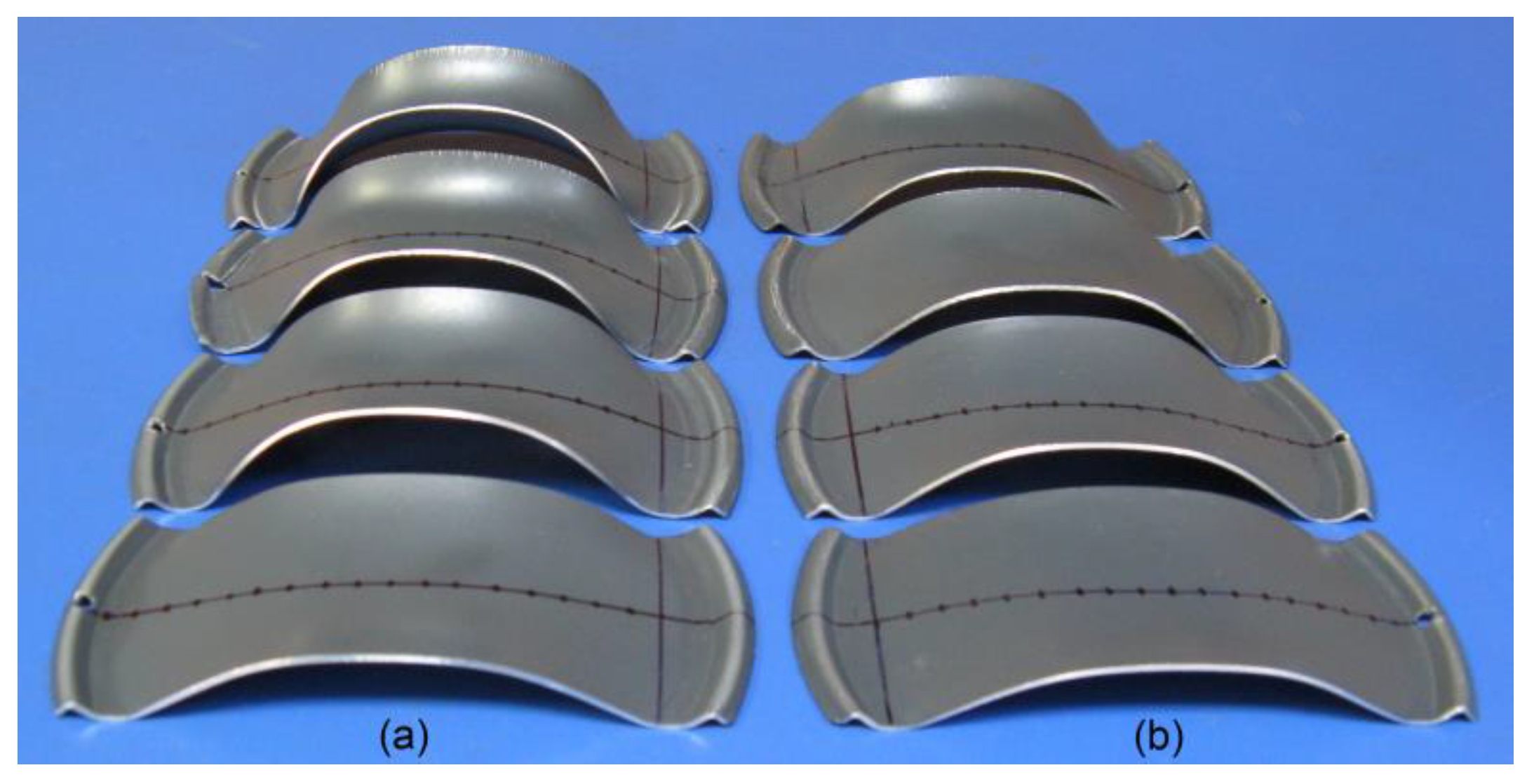
For the last set of tests, deformation energy with values between 0.900 and 1.600 kJ was applied. Some of the SDC and SSCg tested by EMF are shown in Figure 8.
A comparative image regarding the interface’s role (SSD or SDC) using the same method of plastic deformation in the occurrence of cracks in the coating layer is shown in Figure 9.
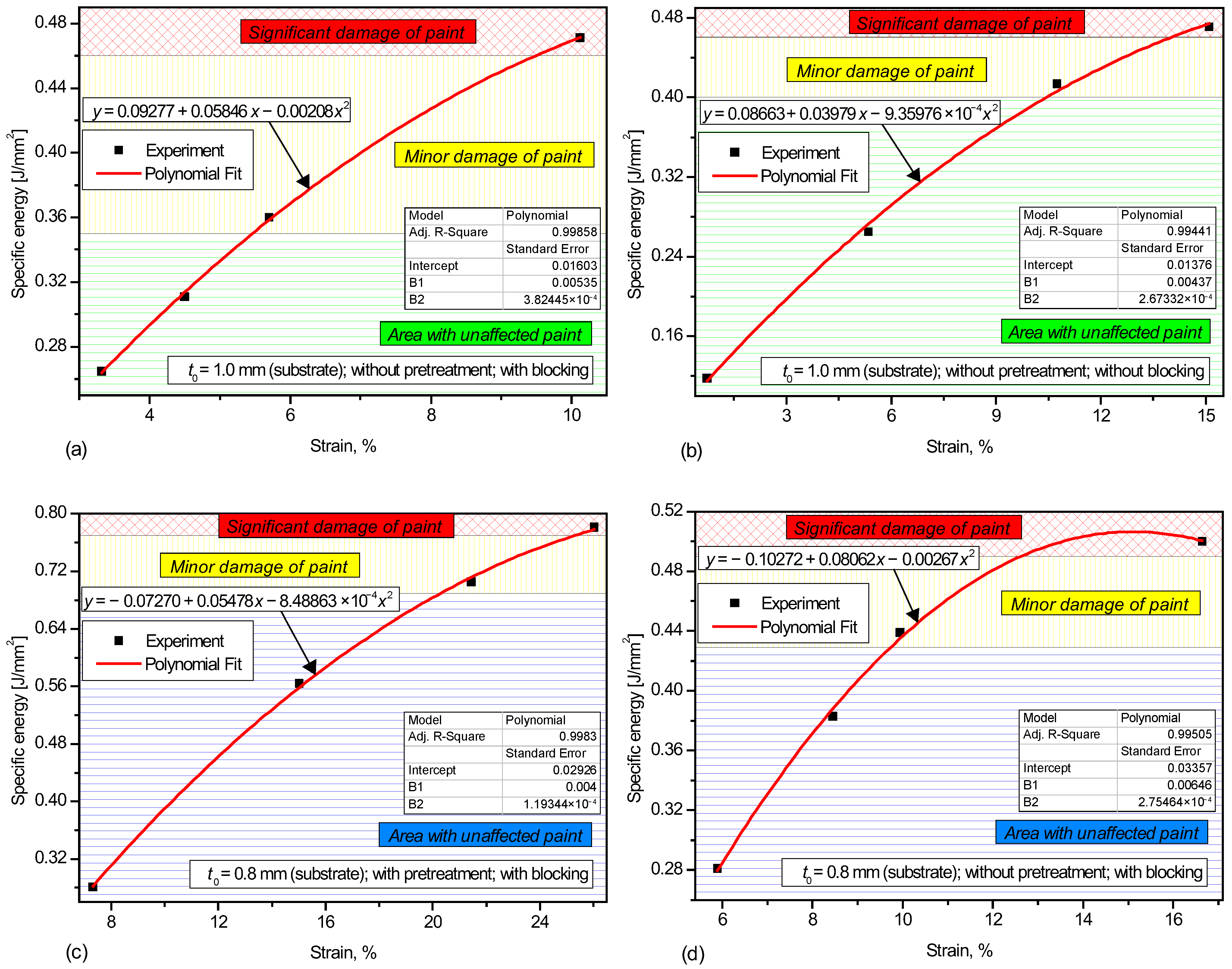
As an indicator for adhesion loss after EMF of painted metal sheets, the specific energy applied to the surface of the specimen is proposed. The specific energy is calculated by the ratio:
E s = E / A
where E is the energy applied and A is the formed portion area of the specimen.
The cumulative influences of the Al 99.0 substrate’s initial thickness of the pretreatment applied (chromatizing) to the base material and of the plastic deformation’s path (with/without blocking) on the adhesion loss of the metal surface’s paint are summarized in Figure 10. From Figure 10a,b we can observe a larger area and a higher limit for maintaining the paint integrity in samples that were electromagnetically formed without blocking vs. those that have been blocked.
The latter were loaded by stretching, with the stress state in the metal–paint structure being less favorable for plastic deformation than in samples formed without blocking the edges.
A better adhesion of the paint was observed on the specimens that were pretreated by degreasing and chromatizing, and the paint incurred a higher plastic deformation of the substrate. In this case, as shown in Figure 10c,d, the first signs of damage to the coating occurs after large strains, which shows that the paint has better resistance after the mechanical shock is applied.
4. Conclusions

From the study of the effects achieved by applying EMF on some aluminum specimens which have the surface painted, the following conclusions have been drawn regarding the degradation of the paint.
  • On the specimens that were electromagnetically formed, with and without blocking, we found that the paint layer has cracked sooner in samples with blocking. The elongation of the base material (at the occurrence of cracks in the paint layer) was 5.70% for SSCb with blocking and almost double (10.74%) for SSCb without blocking.
  • Degradation of paint after plastic deformation was lower in the specimens that had the surface prepared by degreasing and chromatizing than in those that had the surface simply cleaned. In the SDC samples, the appearance of the first cracks in the coating layer occurred for an elongation of the base material of about 21%, while the SSCg samples’ first cracks occurred at a substrate elongation of only 10%.
  • The importance of surface pretreatment for painting of workpieces to be EMF is clearly shown by the differences that appear between SDC and SSCg, the forming degree of Al 99.0 without paint layer degradation being double in SDC under the same working conditions. Experiments performed in this paper show that pretreatment of workpieces (chromatizing or otherwise) is required to achieve an increased coating adhesion and that EMF must be executed in a controlled manner in order to avoid paint degradation on finished parts.
  • Pre-painted workpieces can be formed through the electromagnetic method. For the success of the process, the forming degree of the support material needs to be correlated with the desired type of coating and with the preparation mode of the metal surface. Bearing in mind the hyperplasticity phenomenon that occurs in the metallic material due to the forming action of the electromagnetic field, paints (or other coating materials) which have higher elastic properties are desirable for industrial applications.

Author Contributions

Conceptualization, D.L.; methodology, D.L. and V.Ș.; software, V.Ș.; validation, D.L. and V.Ș.; investigation, D.L. and V.Ș.; resources, D.L.; data curation, D.D.L.; writing—original draft preparation, D.D.L.; writing—review and editing, D.L.; visualization, D.D.L.; supervision, D.L. All authors have read and agreed to the published version of the manuscript.

Funding

This research received no external funding.

Institutional Review Board Statement

Not applicable.

Informed Consent Statement

Not applicable.

Data Availability Statement

The original contributions presented in this study are included in the article. Further inquiries can be addressed to the corresponding author.

Acknowledgments

The authors would like to thank Eng. Tiberiu Ţăranu (Edmario Ltd. Iasi, Romania) for granted technical support for performing coatings in electrostatic field and adhesion tests of specimens before plastic deformation. Also, the authors thank Nicanor Cimpoeşu, PhD (Technical University of Iasi, Romania) for taking SEM images of the electromagnetically formed samples.

Conflicts of Interest

Author Vasile Șchiopu was employed by the company Micronetics Ltd. Author Dorian D. Luca was employed by the company Help Flux Ltd. The remaining author declare that the research was conducted in the absence of any commercial or financial relationships that could be construed as a potential conflict of interest.

References

  1. He, X.; Welo, T.; Ma, J. In-process monitoring strategies and methods in metal forming: A selective review. J. Manuf. Process. 2025, 138, 100–128. [Google Scholar] [CrossRef]
  2. Khan, Z.; Khan, M.; Yook, S.-J.; Khan, A.; Younas, M.; Zahir, M.Z.; Asad, M. Dynamic analysis of closed die electromagnetic sheet metal forming to predict deformation and failure of AA6061-T6 alloy using a fully coupled finite element model. Materials 2022, 15, 7997. [Google Scholar] [CrossRef]
  3. Beckschwarte, B.; Heidhoff, J.; Langstädtler, L.; Schenck, C.; Riemer, O.; Kuhfuss, B. Impact of die coatings on forming conditions in electromagnetic embossing of thin sheet metal. Key Eng. Mater. 2022, 926, 1725–1735. [Google Scholar] [CrossRef]
  4. Polyakova, A.; Stepanov, E.V.; Provder, T.; Hiltner, A.; Baer, E. Relationship of coating failure to deformation in the deep drawn cup. J. Adhes. 2000, 72, 37–50. [Google Scholar] [CrossRef]
  5. Brezolin, A.; dos Santos, T.; Rosa, P.A.R.C.; Paese, E.; Geier, M.; Rossi, R. Assessment of two different constitutive models in high speed forming. In Proceedings of the 7th International Symposium on Solid Mechanics (MECSOL 2019), Sao Carlos, Brazil, 15–17 April 2019. [Google Scholar] [CrossRef]
  6. Chen, M.; Xiao, H.; Wang, Z.; Wang, J.; Zuo, C.; Yang, W. Investigation of the role of the initial workpiece diameter in deformation control in electromagnetic sheet forming. Electronics 2024, 13, 3828. [Google Scholar] [CrossRef]
  7. Cai, D.; An, H.; Li, G.; Ou, H.; Cui, J.; Jiang, H. Local flanging process on a curved wind deflector using electromagnetic forming. J. Manuf. Process. 2022, 84, 1030–1041. [Google Scholar] [CrossRef]
  8. Heinzel, H.; Ramezani, M.; Neitzert, T. Experimental investigation of the formability of organic coated steel sheet metal. Procedia Manuf. 2015, 1, 854–865. [Google Scholar] [CrossRef]
  9. Kamal, M. A Uniform Pressure Electromagnetic Actuator for Forming Flat Sheets. Ph.D. Thesis, The Ohio State University, Columbus, OH, USA, 2005. Available online: https://etd.ohiolink.edu/acprod/odb_etd/ws/send_file/send?accession=osu1127230699&disposition=inline (accessed on 8 June 2025).
  10. Fraunhofer IWU. Electromagnetic Forming; Fraunhofer Institute for Machine Tools and Forming Technology IWU: Chemnitz, Germany, 2025; Available online: https://www.iwu.fraunhofer.de/en/research/range-of-services/Competence-from-A-to-Z/forming/sheet-metal-forming/electromagnetic-forming.html (accessed on 8 June 2025).
  11. Thomas, J.D.; Triantafyllidis, N. On electromagnetic forming processes in finitely strained solids: Theory and examples. J. Mech. Phys. Solids 2009, 57, 1391–1416. [Google Scholar] [CrossRef]
  12. Liu, Z.; Chen, H. Deformation mechanism and failure-tolerant characteristics of polymer-coated sheet metal laminates subjected to different loading conditions. J. Mater. Res. Technol. 2020, 9, 3907–3923. [Google Scholar] [CrossRef]
  13. Sorce, F.S.; Ngo, S.; Lowe, C.; Taylor, A.C. Quantification and analysis of coating surface strains in T-bend tests. Int. J. Adv. Manuf. Technol. 2021, 113, 1125–1142. [Google Scholar] [CrossRef]
  14. Sorce, F.S.; Ngo, S.; Lowe, C.; Taylor, A.C. Quantification of coating surface strains in Erichsen cupping tests. J. Mater. Sci. 2019, 54, 7997–8009. [Google Scholar] [CrossRef]
  15. Ciccarelli, D.; Forcellese, A.; Greco, L.; Mancia, T.; Pieralisi, M.; Simoncini, M.; Vita, A. Deformation behavior of pre-painted steel sheets. Procedia CIRP 2021, 99, 266–271. [Google Scholar] [CrossRef]
  16. Forcellese, A.; Mancia, T.; Simoncini, M. Tensile behavior and formability of pre-painted steel sheets. Metals 2020, 10, 53. [Google Scholar] [CrossRef]
  17. Muto, A.; Toshin, K.; Shibao, F.; Ueda, K. Effect of melamine enrichment on the structure of water-based polyester/melamine films and properties of pre-painted steel sheets. Prog. Org. Coat. 2021, 150, 105963. [Google Scholar] [CrossRef]
  18. Shisode, M.; Hazrati, J.; Mishra, T.; de Rooij, M.; ten Horn, C.; Beeck, J.; van den Boogaard, T. Modeling boundary friction of coated sheets in sheet metal forming. Tribol. Int. 2021, 153, 106554. [Google Scholar] [CrossRef]
  19. Dessie, J.E.; Lukacs, Z. The effect of pre-painting and W-temper forming on springback. Pollack Period. Int. J. Eng. Inf. Sci. 2024, 19, 54–60. [Google Scholar] [CrossRef]
  20. Vayeda, R.; Wang, J. Adhesion of coatings to sheet metal under plastic deformation. Int. J. Adhes. Adhes. 2007, 27, 480–492. [Google Scholar] [CrossRef]
  21. Barai, P.; Weng, G.J. Mechanics of a nanocrystalline coating and grain-size dependence of its plastic strength. Mech. Mater. 2011, 43, 496–504. [Google Scholar] [CrossRef]
  22. Bouzakis, K.D.; Skordaris, G.; Bouzakis, E. Methods for determining coating’s strength properties changes after inducing plastic or elastic residual stresses. Procedia Eng. 2011, 19, 34–39. [Google Scholar] [CrossRef]
  23. Barletta, M.; Vesco, S.; Trovalusci, F. Effect of the substrate and interface on micro-scratch deformation of epoxy-polyester powder coatings. Prog. Org. Coat. 2012, 74, 712–718. [Google Scholar] [CrossRef]
  24. Mézin, A. Increasing bending: A novel straightforward method for testing the mechanical behaviour of coatings and deposited films. Eng. Fract. Mech. 2012, 91, 51–61. [Google Scholar] [CrossRef]
  25. Huang, Y.H.; Wang, J. Prediction of coating adhesion loss due to stretching. Int. J. Adhes. Adhes. 2013, 40, 49–55. [Google Scholar] [CrossRef]
  26. Giannakopoulos, I.; Taylor, A.C. A modelling study of the visco-elastic behaviour of polyester-based coil coatings. Prog. Org. Coat. 2013, 76, 1556–1566. [Google Scholar] [CrossRef]
  27. Zhang, J.Y.; Wang, Y.Q.; Liu, G.; Sun, J. Plastic deformation characteristics of Cu/X (X Cu Zr, Zr) nanolayered materials. Appl. Surf. Sci. 2014, 321, 19–23. [Google Scholar] [CrossRef]
  28. Zhu, W.; Yang, L.; Guo, J.W.; Zhou, Y.C.; Lu, C. Determination of interfacial adhesion energies of thermal barrier coatings by compression test combined with a cohesive zone finite element model. Int. J. Plast. 2015, 64, 76–87. [Google Scholar] [CrossRef]
  29. Schiel, M.; Kreling, S.; Unger, C.; Fischer, F.; Dilger, K. Behavior of adhesively bonded coated steel for automotive applications under impact loads. Int. J. Adhes. Adhes. 2015, 56, 32–40. [Google Scholar] [CrossRef]
  30. Son, Y.K.; Ko, D.C.; Kim, B.M. Prediction of delamination and tearing during stamping of polymer-coated metal sheet. J. Mater. Process. Technol. 2015, 220, 146–156. [Google Scholar] [CrossRef]
  31. SR EN ISO 6892-1; Metallic Materials. Tensile Testing. Part 1: Method of Test at Room Temperature (in Romanian). ASRO: București, Romania, 2020.
  32. SR EN ISO 2360; Non-Conductive Coatings on Nonmagnetic Electrically Conductive Base Metals. Measurement of Coating Thickness. Amplitude-Sensitive Foucault Currents Method (in Romanian). ASRO: București, Romania, 2018.
  33. SR EN ISO 2409; Paints and Varnishes. Cross-Cut Test (in Romanian). ASRO: București, Romania, 2020.
  34. SR EN ISO 6272-1; Paints and Varnishes. Rapid Deformation (Impact Resistance) Tests. Part 1: Falling-Weight Test, Large-Area Indenter (in Romanian). ASRO: București, Romania, 2012.
Figure 1. Tensile test curves for the substrate.
Jmmp 09 00259 g001
Figure 2. Apparatuses for checking the coating adhesion (a) and tested specimens (b).
Jmmp 09 00259 g002
Figure 3. Schematic view of EMF tests tools.
Jmmp 09 00259 g003
Figure 4. EMF equipment used for experimental tests.
Jmmp 09 00259 g004
Figure 5. View of SSCb tested by EMF: (a) with blocking; (b) without blocking.
Jmmp 09 00259 g005
Figure 6. Profile of SSCb tested and the location of cracks: (a) with blocking; (b) without blocking.
Jmmp 09 00259 g006
Figure 7. Painted Al 99.0 sheet tested by EMF: (a) unaffected paint layer; (b) minorly affected paint; (c) majorly affected paint (crack).
Jmmp 09 00259 g007
Figure 8. View of samples tested by EMF with blocking: (a) SDC; (b) SSCg.
Jmmp 09 00259 g008
Figure 9. Profile of samples tested and location of cracks: (a) SDC; (b) SSCg.
Jmmp 09 00259 g009
Figure 10. Cumulative influences on paint damage in samples tested by EMF: (a) and (b) SSCb; (c) SDC; (d) SSCG.
Jmmp 09 00259 g010
Table 1. Chemical composition of the EN AW-1200 (sheet thickness 0.8 mm).
Si + FeCuMnZnTiOthers (Each)Others (Total)Al
0.600.050.050.100.050.050.1599.00
Table 2. Mechanical properties of substrate.
Material/Specimen CodeE [GPa]Rp0.2 [MPa]Rm [MPa]A80, %
EN AW-1200/0°59.289109.096125.3872.174
EN AW-1200/45°70.084107.237117.9613.229
EN AW-1200/90°80.172123.172134.7432.853
Average values
69.848113.168126.0302.749
Table 3. Characteristics of paint deposited on SSCb.
CharacteristicsValue
AdhesionGt 0
Gloss 60°90 GU
Conical on mandrel testover 3 mm
Erichsen test>5 mm
Impact test, energy>2.5 Nm
Table 4. Characteristics of paint deposited on SDC.
CharacteristicsValue
AdhesionGt 0
Gloss 60°30 GU
Conical on mandrel testover 3 mm
Erichsen test>5 mm
Impact test, energy>2.5 Nm
Table 5. The coil and circuit parameters.
CoilCircuit Parameters
Coil resistance0.71 mΩCircuit resistance10.89 mΩ
Coil inductance0.92 µHCircuit inductance1.84 µH
Number of turns5Capacitance200 µF
Table 6. Elongation of SSCb formed with blocking.
No.Energy, E [kJ]Elongation, ε %Observations
11.60010.12Major cracks
20.9003.32No cracks
31.2255.70Minor cracks
41.0564.50No cracks
Table 7. Elongation of SSCb formed without blocking.
No.Energy, E [kJ]Elongation, ε %Observations
10.4000.73No cracks
20.9005.35No cracks
31.60015.10Major cracks
41.40610.74Minor cracks
Table 8. Elongation of SCD after forming with blocking.
No.Energy, E [kJ]Elongation, ε %Observations
10.9007.31No cracks
22.50026.03Major cracks
32.25621.45Minor cracks
41.80615.03No cracks
Table 9. Elongation of SSCg after forming with blocking.
No.Energy, E [kJ]Elongation, ε %Observations
11.60016.66Major cracks
20.9005.89No cracks
31.2258.45No cracks
41.4069.94Minor cracks
Disclaimer/Publisher’s Note: The statements, opinions and data contained in all publications are solely those of the individual author(s) and contributor(s) and not of MDPI and/or the editor(s). MDPI and/or the editor(s) disclaim responsibility for any injury to people or property resulting from any ideas, methods, instructions or products referred to in the content.