Article

Efficient Manufacturing of Steerable Eversion Robots with Integrated Pneumatic Artificial Muscles

by
Thomas Mack
*,†,
Cem Suulker
,
Abu Bakar Dawood
and
Kaspar Althoefer
Centre for Advanced Robotics @ Queen Mary, School of Engineering and Materials Science, Queen Mary University of London, London E1 4NS, UK
*
Author to whom correspondence should be addressed.
Thomas Mack and Cem Suulker are joint first authors; they contributed equally.
J. Manuf. Mater. Process. 2025, 9(7), 223; https://doi.org/10.3390/jmmp9070223
Submission received: 6 May 2025 / Revised: 17 June 2025 / Accepted: 20 June 2025 / Published: 1 July 2025
(This article belongs to the Special Issue Advances in Robotic-Assisted Manufacturing Systems)

Abstract

Soft-growing robots based on the eversion principle are renowned for their ability to rapidly extend along their longitudinal axis, allowing them to access remote, confined, or otherwise inaccessible spaces. Their inherently compliant structure enables safe interaction with delicate environments, while their simple actuation mechanisms support lightweight and low-cost designs. Despite these benefits, implementing effective navigation mechanisms remains a significant challenge. Previous research has explored the use of pneumatic artificial muscles mounted externally on the robot’s body, which, when contracting, induce directional bending. However, this method only offers limited bending performance. To enhance maneuverability, pneumatic artificial muscles embedded in between the walls of double-walled eversion robots have also been considered and shown to offer superior bending performance and force output as compared to externally attached muscle. However, their adoption has been hindered by the complexity of the current manufacturing techniques, which require individually sealing the artificial muscles. To overcome this multi-stage fabrication approach in which muscles are embedded one by one, we propose a novel single-step method. The key to our approach is the use of non-heat-sealable inserts to form air channels during the sealing process. This significantly simplifies the process, reducing production time and effort and improving scalability for manufacturing, potentially enabling mass production. We evaluate the fabrication speed and bending performance of robots produced in this manner and benchmark them against those described in the literature. The results demonstrate that our technique offers high bending performance and significantly improves the manufacturing efficiency.

1. Introduction

There is growing demand for robotic systems capable of accessing and operating within confined, hazardous, or otherwise inaccessible environments, notably in fields such as medicine, nuclear decommissioning, construction, telecommunication, archaeology, and search and rescue. Typically, these “hard-to-access” areas are either physically constrained or pose safety risks to human operators, such as high radiation exposure (e.g., in nuclear decommissioning) or structurally unstable surroundings (e.g., in search and rescue).
One of the critical capabilities required in such applications is the ability to travel significant distances through narrow or tortuous channels while transporting sensors, tools, or payloads for inspection, maintenance, or repair tasks.
Even though mobile robots have traditionally been deployed for this purpose [1], their performance is often limited by mechanical complexity, susceptibility to damage, difficulty regarding recovery if stranded, and challenges in navigating highly irregular or cluttered spaces [2]. Continuum robots—snake-like systems with high length-to-diameter ratios—have emerged as a promising alternative due to their ability to navigate through narrow openings and bend compliantly [3,4].
A notable advancement in this field is the development of eversion robots, which are also referred to as soft-growing or vine robots [2,5]. Unlike traditional continuum robots, eversion robots grow from the tip by inverting their body structure outward under fluidic pressure (Figure 1). This mechanism is analogous to the way a jacket sleeve might unfold from the inside out. Constructed from airtight materials such as fabrics or polyethylene, these robots undergo longitudinal extension with zero environmental friction, making them particularly well-suited to navigating long winding pathways or delicate environments in which minimal friction with their surroundings is paramount [6,7,8].
Eversion robots can extend to many times their original length while applying minimal force to the surrounding surfaces. Their compliant nature allows them to conform to the geometry of the environment, enabling passive bending around obstacles [9]. They can also, to a certain degree, follow pre-existing environmental paths. They can, for example, navigate around gradual turns (e.g., 45° pipe bends) but often require additional assistance to handle sharper turns or to navigate open spaces [10,11,12].
To address these limitations, several maneuvering techniques have been developed to enable enhanced control and steering in both constrained and unconstrained environments [13]. These techniques generally fall into two categories: active steering and predetermined steering. Active steering enables real-time directional control through actuation systems embedded in or attached to the robot, while predetermined steering relies on built-in geometrical features or structural design to dictate the robot’s trajectory during deployment [14,15].
Among the active steering approaches, the use of pneumatic artificial muscles (PAMs) is particularly prominent [14,16]. When pressurized, PAMs contract along their length, causing asymmetric shortening on one side of the robot and thereby inducing bending. These actuators can be implemented as continuous elements or localized segments depending on the desired maneuverability. Integration strategies vary as well: PAMs can either be externally attached [10] or structurally embedded within the robot body [16,17]. While external attachment offers ease of fabrication, embedded solutions yield greater performance in terms of bending angle and force output [14].
The contribution of this paper is a manufacturing method that facilitates the creation of eversion robots with PAMs embedded into the robot wall. The critical improvement in our novel method emanates from the use of fabric strips, which act as non-heat-sealable inserts to form air channels during the sealing process. This design enables the creation of eversion robots with integrated PAMs without the need for complex multi-stage fabrication. Using this method, we can achieve the high-performance bending offered by integrated PAMs while reducing the complexity of the manufacturing process. In Section 2, Materials and Methods, we provide details of our method for both heat-sealable and non-heat-sealable materials. Section 3, Evaluation, benchmarks the fabrication speed and the performance of the resulting robot prototypes, comparing them to the data available in the literature. In Section 4, Discussion and Conclusion, we outline and analyze the key findings and improvements presented in the paper.

2. Materials and Methods

The fabrication method introduced in this study utilizes a heat-based approach to integrate PAMs into eversion robots (Figure 2). A key improvement in this method comes from the use of fabric strips as non-heat-sealable inserts (Figure 2 Left b, and Right c), which serve to define and preserve the air channels during the sealing process. This approach enables the efficient creation of eversion robots with integrated PAMs without resorting to complex multi-stage fabrication procedures, as, for example, described in [16,17]. As a result, the manufacturing process is significantly streamlined, reducing both production time and effort whilst maintaining fabrication quality.
Our method is compatible with a wide range of airtight materials. The most commonly used materials for eversion robots are low-density polyethylene (LDPE) and coated fabrics [18]. To demonstrate the versatility of our technique, we provide two representative case studies in this paper—one using LDPE and the other using polyurethane (PU)-coated fabric.
These two material classes differ in their sealing requirements, and the application of our novel method is tailored accordingly:
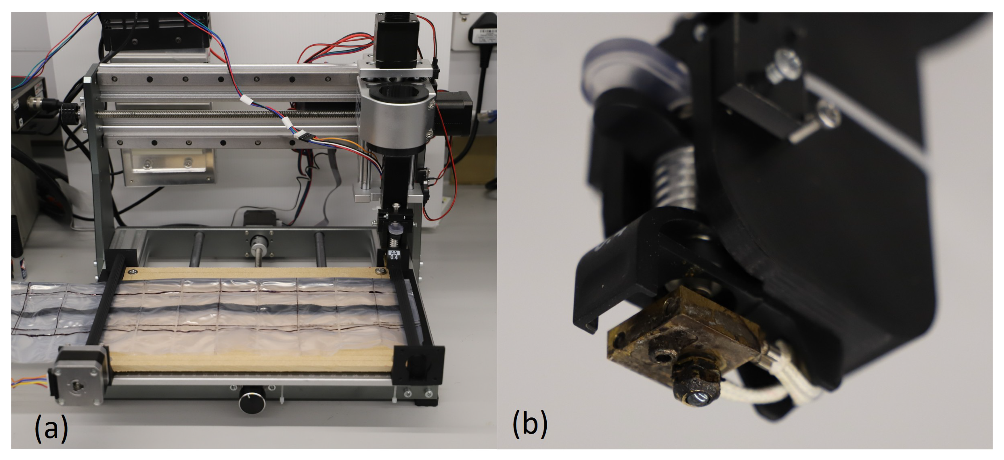
  • Heat-sealable materials (e.g., LDPE) are processed using an impulse heat sealer.
  • Non-heat-sealable materials (e.g., PU-coated fabrics) are sealed using a heat press with TPU bonding strips.
Furthermore, this novel method can be extended to alternative sealing technologies such as ultrasonic welding and laser welding.

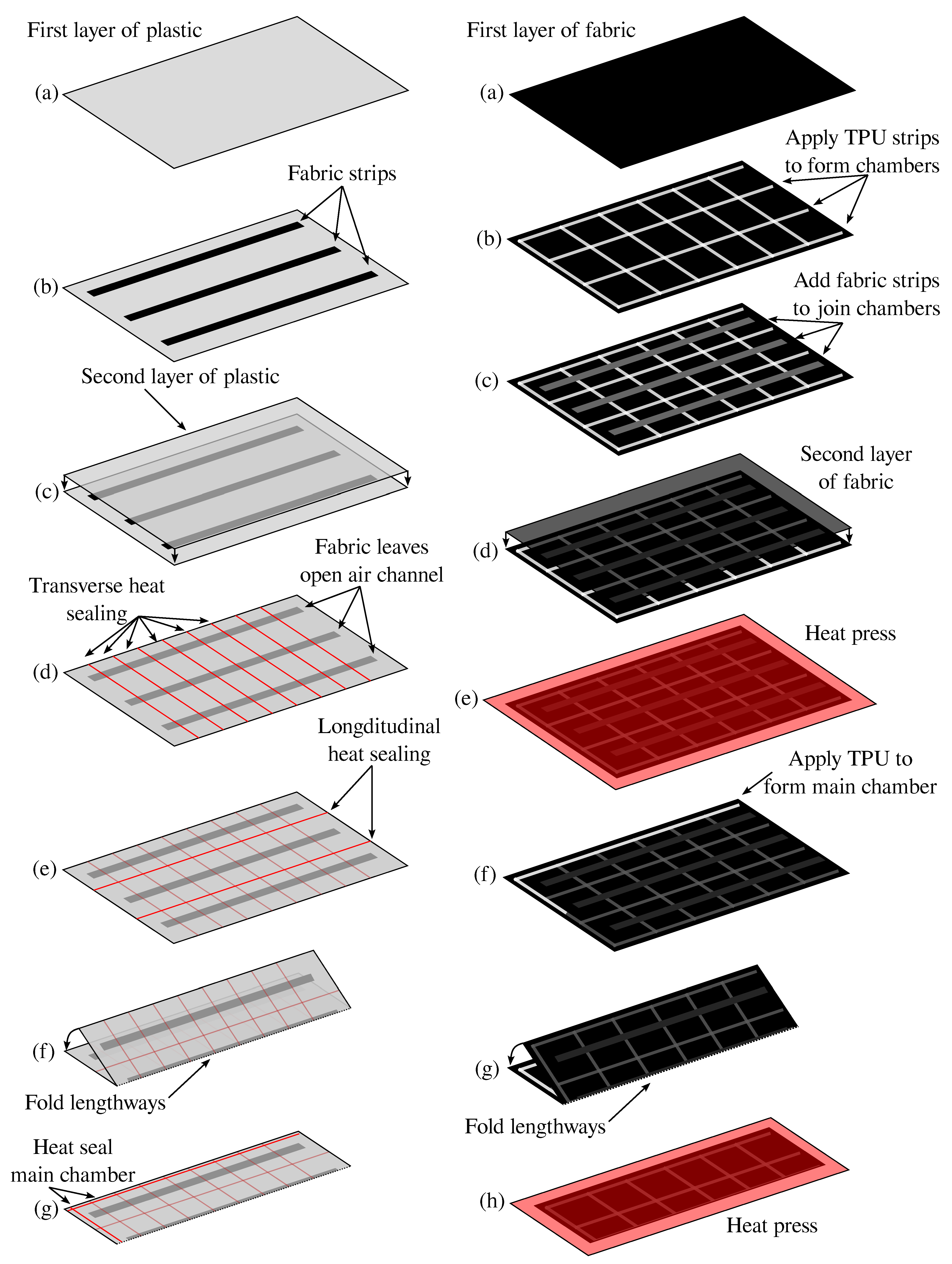
2.1. Fabrication Using a Heat-Sealable Material (e.g., LDPE)

This design methodology can be used to integrate navigation PAMs into eversion robots constructed from heat-sealable materials such as LDPE, TPU, and TPU-coated fabrics. These materials constitute most thermoplastics, but the methodology does not apply to certain materials conventionally used in soft robotics, such as silicone. To ensure rapid and precise joining, sealing in this fabrication process is achieved via a heat source.
In this section, we provide step-by-step fabrication guidelines for the manual manufacture of a heat-sealable material using our method, and then discuss possible improvements as well as its suitability for automation using a custom-modified Computer-Aided Manufacturing (CAM) setup.
Manual Fabrication
Traditionally, constructing an eversion robot with integrated PAMs out of LDPE has been a multi-step labor-intensive task [16,17]. Each PAM typically requires multiple welds, increasing both the fabrication time and complexity, which is most likely the reason for their absence in the current literature. With the proposed method, a single segment of PAM can now be integrated with just one heat-sealing step, significantly streamlining the process.
The materials required for this method include LDPE sheets and fabric strips. First, two identical rectangular LDPE sheets are cut to size (Figure 2 Left a). The sheet dimensions are selected based on the desired robot diameter. For instance, to produce a robot 57 mm in diameter, the sheets are cut 200 mm wide (180 mm plus a seam allowance of 10 mm each side) and 1.5 m long. Fabric strips are then positioned on the base sheet to define the air channels between the PAMs (Figure 2 Left b). A second LDPE sheet is placed on top (Figure 2 Left c), and a heat seal line is applied across the width using an impulse sealer (Figure 2 Left d). The fabric strips act as insulation, preventing sealing at their locations and ultimately creating internal air channels.
Next, longitudinal sealing lines are added to divide the PAMs. In our prototype, two longitudinal seals were used to create three parallel PAMs (Figure 2 Left e). The assembly is then folded lengthwise (Figure 2 Left f) and sealed along the front and side edges to form a cylindrical structure (Figure 2 Left g).
Once completed, the integrated PAMs can be activated by an air supply to inflate channels connected by the unsealed fabric strip regions.
Automated Fabrication
Our novel method of fabricating maneuverable eversion robots enables automation of the sealing process. Two promising applications of our method are a conveyor-belt-based impulse sealing system and a CNC machine equipped with a programmable heat source and material feeding via rollers.
In a conveyor-belt impulse sealing setup, heat-sealable sheets move along the belt while sealing heads apply heat at predefined locations. Creating integrated air channels typically requires multiple sealing steps for each channel. To avoid sealing over the intended air channel paths, the system must activate the impulse sealer at least ( c + 1 ) ( n + 1 ) times for the transverse seals, where n is the number of PAMs on one air channel and c is the number of air channels. Although custom impulse sealers with gaps can be manufactured to reduce the number of steps, they significantly increase production costs and need redesigning for different robot geometries.
By incorporating our novel method, air channels are defined using strategically placed fabric strips, which act as non-sealable barriers. This allows the impulse sealer to operate in a single pass, eliminating the need for multiple seals or custom sealing tools. This reduces the number of transverse seals to n + 1 . As a result, the production line becomes either faster or more cost-effective (or both) and can easily adapt to different robot dimensions without requiring custom hardware.
For more versatile fabrication, a CNC-based approach offers even greater flexibility. In this configuration, a programmable heat source—such as a hot roller or laser—is mounted on a CNC machine and follows a prescribed sealing path over the material. However, traditional CNC-based sealing methods encounter challenges at the start and end of air channels, where the sealing head has to lift and re-engage. These discontinuities can introduce weak points due to overheating in the material, which are then prone to rupture under pneumatic pressure, compromising the robot’s structural integrity.
Our novel method effectively addresses this issue. With fabric strips placed at appropriate locations, the sealing head can move continuously across the surface without needing to disengage. The fabric strips prevent bonding at specific areas, clearly defining the air channel boundaries while maintaining a uniform and durable seal along the rest of the material. This continuous sealing not only simplifies the process but also significantly improves the robot’s durability under actuation pressure.
To demonstrate the feasibility of this approach, we modified a desktop CNC router—a Genmitsu 3020-PRO MAX similar to [19] (Figure 3a). The machine is equipped with a custom-designed, heated, spring-loaded ball roller (Figure 3b), which can rotate freely and offers adjustable temperature control to support a variety of thermoplastic materials.
To fabricate the eversion robot, two layers of heat-sealable sheets with inserted fabric strips are fed into the CNC machine. The CNC code determines the sealing path, as shown in Figure 2 (Left). Toothed rollers were integrated into the system for continuous feeding. While the folding of the material is currently conducted manually, an automated folding mechanism could potentially be integrated, further streamlining the process.

2.2. Fabrication Using a Non-Heat-Sealable Material (e.g., Pu-Coated Fabric)

This section presents a method for integrating navigation PAMs into eversion robots composed of non-heat-sealable yet airtight materials, such as PU-coated fabrics, but it could also be applied to other flexible airtight sheets to which thermoplastics can be bonded. PU-coated fabrics offer greater flexibility than TPU-coated alternatives, but, due to their lower plastic content, conventional heat-sealing or ultrasonic welding methods are ineffective. Usually, a sewing machine is used to bond the material, before sealing with either vinyl [20,21], or latex [16]. Our novel fabrication technique utilizes a heat press for bonding TPU to PU-coated fabric, enabling integration without compromising flexibility.
Manual Fabrication
Prior to the introduction of this method, constructing integrated PAMs using non-heat-sealable materials involved complex and time-consuming techniques. As indicated, the material would be sewn, and the seams sealed with latex or vinyl [16]. However, latex seals degrade over time and can delaminate, while vinyl stiffens the material and limits maneuverability. These methods also require multiple fabrication steps. In contrast, the new technique allows the formation of a PAM segment with a single press operation.
The required materials include airtight PU-coated fabric, TPU strips (DoonX, GXFU150 0.4 mm thick), and fabric spacers. We used TPU strips with a width of 10 mm; thinner strips may also be suitable. Two identical rectangular PU-coated fabric sheets are cut (Figure 2 Right a) and sized according to the intended robot diameter. By way of illustration, to construct a robot with a diameter of 80 mm, each sheet is cut to a width of 251 mm (with 20 mm seam allowance) and a length of 42 cm.
TPU strips are placed on the base sheet to define the outer edges of the PAMs (Figure 2 Right b) and held down by lightly pressing with an iron. Fabric spacers are then placed in the central areas where the air channels will be formed (Figure 2 Right c). A second fabric sheet is positioned over the top (Figure 2 Right d), and the assembly is bonded using a heat press (Figure 2 Right e). The TPU strips melt and fuse the fabric layers, while the fabric spacers prevent bonding at the air channel locations.
To prepare the robot’s main chamber, additional TPU strips are placed along the side edges of the sheet (Figure 2 Right f). On the folded edge, the TPU should cover only half the width as the fold will bring one side into contact with the other. The sheet is then folded lengthwise (Figure 2 Right g) and sealed using the heat press to complete the structure (Figure 2 Right h).
Once fabrication is complete, the robot is ready for eversion and navigation. Inflating the channels formed by the unsealed fabric spacers activates the PAMs, enabling controlled bending of the robot body.

3. Evaluation

Prototypes fabricated using our method are evaluated based on two key metrics: fabrication efficiency and bending angle performance. To assess fabrication efficiency, we compare the number of times the sealing device is activated and the number of material preparation steps required against the equivalent figures for conventional manufacturing techniques. Bending performance is evaluated by measuring the bending angles achieved by the prototypes and benchmarking them against the results reported by Kübler et al. [14]. To ensure a fair comparison, the prototypes were fabricated using identical dimensions to those described in the referenced study.
Two eversion robots are constructed manually, following the step-by-step procedures outlined in Figure 2. One prototype is fabricated from LDPE, a widely used heat-sealable material, while the other is constructed using PU-coated fabric, a non-heat-sealable but airtight material. In both cases, PAMs are integrated continuously along the length of the robot body to enable active steering.
Parameters that would have an effect on this evaluation are the robot’s overall diameter and length, PAM width and length, the width of the fabric strips used to create internal air channels, and, for the PU-coated prototype, the width of the TPU strips used to bond the layers. A full list of the geometric and material specifications for the fabricated robots is provided in Table 1.

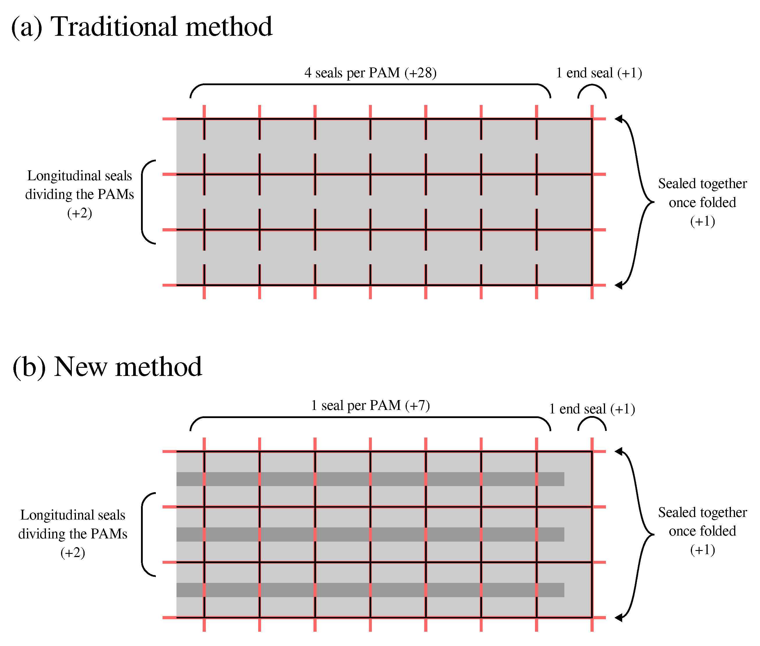
3.1. Fabrication Speed

The primary objective of this study is to streamline the integration of PAMs into eversion robots by significantly reducing the fabrication time. The most time-consuming stage in traditional manufacturing is the construction of the internal chambers for the PAMs. For heat-sealable materials, this involves repeatedly applying an impulse sealer to melt and join the layers. For non-heat-sealable materials, the process requires cutting, aligning, and placing individual TPU strips—tasks that need to be performed meticulously and that are therefore labor-intensive.
To quantify the benefits of our methodology, we recorded the number of times these repetitive actions (i.e., impulse sealing or TPU strip placement) are required in each approach. For this evaluation, a 42-centimeter-long eversion robot was fabricated, with three sets of PAMs (each 6 cm long and 6 cm wide) implemented along three sides of the robot to achieve three-dimensional steerability. This design includes a total of 21 PAMs and three independent air channels running the length of the robot.
The fabrication requirements for both methods are summarized in Figure 4. In the traditional approach, the creation of a single PAM set (consisting of three chambers) requires 4 impulse sealer activations or TPU strip placements. This results in a total of 28 repetitions for all seven sets. In contrast, the novel method reduces the number of sealing actions or TPU alignments to just 1 per set.
Notably, those sealing operations that are unrelated to the creation of air channels remain unchanged between the two approaches. The use of fabric strips in our method is specifically designed to streamline the air channel formation without affecting the rest of the robot’s structure.
In summary, our novel fabrication technique reduces the total number of required sealing or alignment operations for three rows of 7 PAMs from 32 to 10, clearly demonstrating a substantial reduction in manufacturing time and effort.

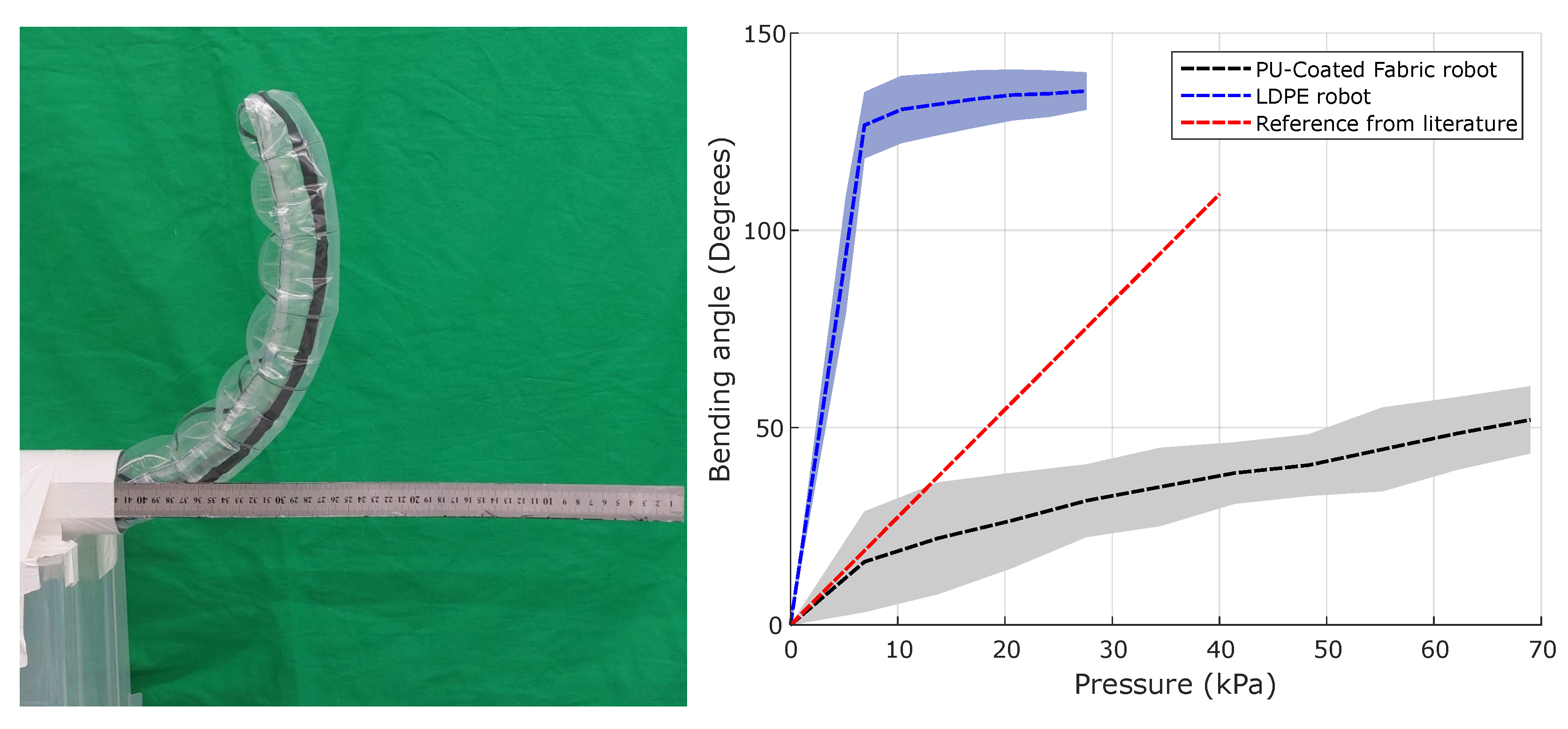
3.2. Bending Performance of the Resulting Robot

To assess the effectiveness of the proposed manufacturing method, we conducted bending angle tests to determine whether the achieved performance is comparable to the values reported in the literature. Specifically, we reference the work by Kübler et al. [14]. The geometric parameters of the robot and PAM are intentionally matched to those used in Kübler’s study to enable a fair comparison.
For testing, each robot is mounted at a fixed point, leaving the first 42 cm free to move. Under its own weight, the robot is allowed to bend upwards. The bending angle is measured from the fixed base to the robot’s tip. During testing, the robot’s main chamber is continuously inflated at 5.2 kPa for both the fabric robot and the LDPE robot—this being the minimum pressure required to maintain eversion. The integrated navigation PAMs are incrementally pressurized using an SMC ITV2050-212BL4 electronic pressure regulator, with steps of 3.5 kPa for the LDPE and 6.9 kPa for the fabric robot. Smaller pressure intervals were used for the LDPE robot because its lower material durability limited the maximum pressure it could safely withstand; this allowed for finer resolution in the data while staying within safe operating limits. Multiple measurements were collected, and the results are presented along with their corresponding standard deviations. The entire process is recorded from the side, and the bending angles are later extracted from still images.
The results of the bending tests are shown in Figure 5. The red line represents the maximum bending angle per unit length (2.6°/cm) achieved in [14] for the same PAM dimensions. The results for both the PU-coated fabric and LDPE robots are overlaid in the plot.
The mean bending angle for the LDPE robot is shown in Figure 5 as a blue dashed line, with the shaded area representing the standard deviation. The prototype achieved a maximum bending angle of 139°, corresponding to 3.3°/cm, at an inflation pressure of 27.6 kPa—exceeding the best result reported by Kubler et al. (2.6°/cm) [14] for a robot with the same dimensions. At this pressure, the mean bending angle is 135° with a standard deviation of 4.7°, equivalent to 3.2°/cm. It is important to note that the novel fabrication method does not inherently improve bending performance. Therefore, the enhanced performance observed here is most likely due to differences in material thickness and/or modulus of elasticity. The maximum pressure the LDPE-based PAMs were able to withstand was 27.6 kPa, a limitation primarily influenced by the material’s thickness and the quality of the sealing.
The maximum achievable pressure for the PAMs in the PU-coated fabric robot was 70 kPa, at which point the robot reached a bending angle of approximately 58° with 8.5° standard deviation, corresponding to 1.4°/cm. This is roughly half the value reported in [14]. The key reason for this performance gap lies in the internal pressure required to maintain eversion. In Kübler et al.’s study, the robot could evert at just 1.75 kPa, and all the tests were conducted using this internal pressure. In contrast, our fabric robot required a minimum of 5.2 kPa to achieve eversion, and the tests were conducted accordingly.
The primary factor behind this higher required pressure is the increased structural stiffness introduced by the layered materials. Our robot comprises one layer of TPU and two layers of fabric, resulting in greater overall thickness. This added thickness contributes not only to higher eversion pressure but also to increased flexural rigidity, which in turn reduces the bending angle achievable per unit of applied PAM pressure.

4. Discussion and Conclusions

This paper introduces a novel fabrication method for eversion robots with integrated PAMs. The proposed approach utilizes fabric strips to define air channels, which enables sealing without blocking air channels. This technique simplifies the manufacturing process, making it significantly easier to produce highly maneuverable eversion robots. This technique is compatible with a wide range of flexible sheet materials, including thermoplastics and airtight fabrics that can be bonded using thermoplastic layers.
Prototypes composed of two different materials were fabricated using the proposed method. For both types, a significant reduction in fabrication time was observed. The prototype constructed from LDPE and sealed using an impulse heat sealer demonstrated promising bending angle performance, reaching 3.3°/cm—surpassing the best value reported in the literature (2.6°/cm) [14]. While this result is encouraging, the performance gain is most likely attributable to differences in material thickness or modulus of elasticity rather than any intrinsic performance-enhancing feature of the method itself. In our work, we focused on reducing the manufacturing complexity. As can be seen from our results, this was achieved. In addition, the bending performance was not impacted by the proposed method when applied to the LDPE eversion robot.
When comparing the two materials, the LDPE robot plateaued with high curvature at low pressure, whereas the fabric robot displayed a gradual bending increase. The fast plateau of the curvature of the LDPE robot was due to the material’s high flexibility. The PAMs will reach their maximum contraction at very low pressure, and increasing the pressure further will not contribute additionally to the curvature. While the fabric robots require higher pressure, they are much more durable and last a high number of cycles. In comparison, the LDPE has much lower durability and can often not survive many cycles due to folding and creasing introducing weaknesses in the material. However, it is much cheaper and can be used for disposable eversion robots. The presented new manufacturing method also makes disposable maneuverable eversion robots much more feasible.
Fabric structures are generally considered to be high performers in soft robotic applications [22,23,24]. However, our prototype constructed from PU-coated fabric with a heat sealer did not achieve the expected bending performance. Specifically, it reached a maximum bending angle of 1.4°/cm, whereas Kübler et al. [14] reported 2.6°/cm for a similarly dimensioned prototype produced using conventional methods.
The primary reason for this underperformance lies in the increased thickness and stiffness of the fabricated structure. The bonding method used in this prototype required two layers of fabric and one layer of TPU between them, resulting in a thicker and less flexible wall. According to beam theory [25,26], the bending stiffness of a material (Equation (1)) is proportional to the cube of its thickness. In the equation, D represents the bending stiffness, E is Young’s modulus, h is the thickness, and σ is Poisson’s ratio:
D = E · h 3 12 ( 1 σ 2 )
Thus, increasing the thickness dramatically increases the stiffness, which not only reduces the robot’s ability to bend but also impacts the efficiency of the eversion process as the material must first unfold from a compacted form. In addition, a seam width of 10 mm was used, which meant that 14.9% of the length of the robot did not contribute to contraction. With smaller seam widths, the bending performance would increase.
Additionally, we tested the seal strength of the prototypes. However, due to the lack of comparable data in the literature, we were unable to provide a direct benchmark. When pull-testing 5-centimeter-long seams, the LDPE robot sealed using the impulse sealer withstood a mean force of 32.8 N with a standard deviation of 1.4 N, while the fabric robot achieved a mean seal strength of 216.0 N with a standard deviation of 4.8 N. We hope this data will serve as a useful reference for future research and comparison.
From these findings, we conclude that the proposed fabrication method is well-suited to heat-sealable materials like LDPE but is less effective when applied to non-heat-sealable materials such as PU-coated fabric. The results also suggest that LDPE, rather than fabric, would produce eversion robots capable of greater bending.
For the coated fabric approach, the preliminary findings suggest that using thinner TPU layers and reducing the seal width could improve the flexibility and bending performance. Future work should investigate these modifications to determine whether they have the potential to overcome the limitations observed in the PU-coated prototype.

Author Contributions

T.M. and C.S. are joint first authors, having contributed equally. Conceptualization, T.M. and C.S.; methodology, T.M. and C.S.; validation, T.M., C.S. and A.B.D.; formal analysis, T.M. and C.S.; investigation, T.M. and C.S.; resources, T.M. and C.S.; data curation, T.M. and C.S.; writing—original draft preparation, T.M. and C.S.; writing—review and editing, T.M., C.S., A.B.D. and K.A.; visualization, T.M., C.S. and A.B.D.; supervision, K.A.; project administration, K.A.; funding acquisition, K.A. All authors have read and agreed to the published version of the manuscript.

Funding

This work is supported by ERC grant EndoTheranostics, 101118626. Funded by the European Union. Views and opinions expressed are, however, those of the author(s) only and do not necessarily reflect those of the European Union or the European Research Council Executive Agency. Neither the European Union nor the granting authority can be held responsible for them. This work was also financially supported by the PALPABLE project, funded by UK Research and Innovation (UKRI) through the UK government’s Horizon Europe funding guarantee [grant # N°101092518] and funded by the European Union. Thomas Mack is supported by an iCASE EPSRC PhD studentship with Nuclear Restoration Services (NRS-Dounreay). Cem Suulker was funded by Ministry of National Education of Türkiye.

Data Availability Statement

Acknowledgments

The authors thank Mish Toszeghi for their valuable help. Huge thanks also to our reviewers for their constructive comments.

Conflicts of Interest

The authors declare no conflicts of interest. The funders had no role in the design of the study; in the collection, analyses, or interpretation of data; in the writing of the manuscript; or in the decision to publish the results.

Abbreviations

The following abbreviations are used in this manuscript:
CNCComputer Numerical Control
LDPELow-Density Polyethylene
PAMsPneumatic Artificial Muscles
PUPolyurethane
TPUThermoplastic Polyurethane

References

  1. Rubio, F.; Valero, F.; Llopis-Albert, C. A review of mobile robots: Concepts, methods, theoretical framework, and applications. Int. J. Adv. Robot. Syst. 2019, 16, 1729881419839596. [Google Scholar] [CrossRef]
  2. Mishima, D.; Aoki, T.; Hirose, S. Development of a pneumatically controlled expandable arm for rescue searches in tight spaces. Int. J. Robot. Res. 2006, 25, 103–110. [Google Scholar] [CrossRef]
  3. Webster, R.J., III; Jones, B.A. Design and kinematic modeling of constant curvature continuum robots: A review. Int. J. Robot. Res. 2010, 29, 1661–1683. [Google Scholar] [CrossRef]
  4. Sadati, S.H.; Naghibi, S.E.; Shiva, A.; Walker, I.D.; Althoefer, K.; Nanayakkara, T. Mechanics of continuum manipulators, a comparative study of five methods with experiments. In Proceedings of the Towards Autonomous Robotic Systems: 18th Annual Conference, TAROS 2017, Guildford, UK, 19–21 July 2017; Springer: Berlin/Heidelberg, Germany, 2017; pp. 686–702. [Google Scholar]
  5. Hawkes, E.W.; Blumenschein, L.H.; Greer, J.D.; Okamura, A.M. A soft robot that navigates its environment through growth. Sci. Robot. 2017, 2, eaan3028. [Google Scholar] [CrossRef] [PubMed]
  6. Putzu, F.; Abrar, T.; Althoefer, K. Plant-inspired soft pneumatic eversion robot. In Proceedings of the 2018 7th IEEE International Conference on Biomedical Robotics and Biomechatronics (Biorob), Enschede, The Netherlands, 26–29 August 2018; IEEE: New York, NY, USA, 2018; pp. 1327–1332. [Google Scholar]
  7. Abrar, T.; Putzu, F.; Konstantinova, J.; Althoefer, K. EPAM: Eversive pneumatic artificial muscle. In Proceedings of the 2019 2nd IEEE International Conference on Soft Robotics (RoboSoft), Seoul, Republic of Korea, 14–18 April 2019; IEEE: New York, NY, USA, 2019; pp. 19–24. [Google Scholar]
  8. Vitanov, I.; Farkhatdinov, I.; Denoun, B.; Palermo, F.; Otaran, A.; Brown, J.; Omarali, B.; Abrar, T.; Hansard, M.; Oh, C.; et al. A Suite of Robotic Solutions for Nuclear Waste Decommissioning. Robotics 2021, 10, 112. [Google Scholar] [CrossRef]
  9. Godaba, H.; Putzu, F.; Abrar, T.; Konstantinova, J.; Althoefer, K. Payload capabilities and operational limits of eversion robots. In Proceedings of the Towards Autonomous Robotic Systems: 20th Annual Conference, TAROS 2019, London, UK, 3–5 July 2019; Springer: Berlin/Heidelberg, Germany, 2019; pp. 383–394. [Google Scholar]
  10. Coad, M.M.; Blumenschein, L.H.; Cutler, S.; Zepeda, J.A.R.; Naclerio, N.D.; El-Hussieny, H.; Mehmood, U.; Ryu, J.H.; Hawkes, E.W.; Okamura, A.M. Vine robots. IEEE Robot. Autom. Mag. 2019, 27, 120–132. [Google Scholar] [CrossRef]
  11. Mack, T.; Al-Dubooni, M.; Althoefer, K. Eversion Robots for Mapping Radiation in Pipes. arXiv 2023, arXiv:2307.10084. [Google Scholar]
  12. Takahashi, T.; Tadakuma, K.; Watanabe, M.; Takane, E.; Hookabe, N.; Kajiahara, H.; Yamasaki, T.; Konyo, M.; Tadokoro, S. Eversion robotic mechanism with hydraulic skeletonto realize steering function. IEEE Robot. Autom. Lett. 2021, 6, 5413–5420. [Google Scholar] [CrossRef]
  13. Behnke, L.; Do, B.H.; Eristoff, S.; Kramer-Bottiglio, R. Interaction Behaviors of a Vine Robot in a Pipe T-Junction. In Proceedings of the 2024 IEEE 7th International Conference on Soft Robotics (RoboSoft), San Diego, CA, USA, 14–17 April 2024; IEEE: New York, NY, USA, 2024; pp. 498–503. [Google Scholar]
  14. Kübler, A.M.; Du Pasquier, C.; Low, A.; Djambazi, B.; Aymon, N.; Förster, J.; Agharese, N.; Siegwart, R.; Okamura, A.M. A comparison of pneumatic actuators for soft growing vine robots. Soft Robot. 2024, 11, 857–868. [Google Scholar] [CrossRef] [PubMed]
  15. Greer, J.D.; Blumenschein, L.H.; Alterovitz, R.; Hawkes, E.W.; Okamura, A.M. Robust navigation of a soft growing robot by exploiting contact with the environment. Int. J. Robot. Res. 2020, 39, 1724–1738. [Google Scholar] [CrossRef]
  16. Abrar, T.; Putzu, F.; Ataka, A.; Godaba, H.; Althoefer, K. Highly manoeuvrable eversion robot based on fusion of function with structure. In Proceedings of the 2021 IEEE International Conference on Robotics and Automation (ICRA), Xi’an, China, 30 May–5 June 2021; IEEE: New York, NY, USA, 2021; pp. 12089–12096. [Google Scholar]
  17. Kübler, A.M.; Rivera, S.U.; Raphael, F.B.; Förster, J.; Siegwart, R.; Okamura, A.M. A multi-segment, soft growing robot with selective steering. In Proceedings of the 2023 IEEE International Conference on Soft Robotics (RoboSoft), Singapore, 3–7 April 2023; IEEE: New York, NY, USA, 2023; pp. 1–7. [Google Scholar]
  18. Blumenschein, L.H.; Coad, M.M.; Haggerty, D.A.; Okamura, A.M.; Hawkes, E.W. Design, Modeling, Control, and Application of Everting Vine Robots. Front. Robot. AI 2020, 7, 548266. [Google Scholar] [CrossRef] [PubMed]
  19. Ou, J.; Skouras, M.; Vlavianos, N.; Heibeck, F.; Cheng, C.Y.; Peters, J.; Ishii, H. aeroMorph-heat-sealing inflatable shape-change materials for interaction design. In Proceedings of the 29th Annual Symposium on User Interface Software and Technology, Tokyo, Japan, 16–19 October 2016; pp. 121–132. [Google Scholar]
  20. Suulker, C.; Skach, S.; Kaleel, D.; Abrar, T.; Murtaza, Z.; Suulker, D.; Althoefer, K. Soft Cap for Vine Robots. In Proceedings of the 2023 IEEE/RSJ International Conference on Intelligent Robots and Systems (IROS), Detroit, MI, USA, 1–5 October 2023; IEEE: New York, NY, USA, 2023; pp. 6462–6468. [Google Scholar]
  21. Suulker, C.; Skach, S.; Kaleel, D.; Abrar, T.; Murtaza, Z.; Suulker, D.; Althoefer, K. Deformable Tip Mount for Soft Growing Eversion Robots. arXiv 2024, arXiv:2401.07855. [Google Scholar]
  22. Suulker, C.; Hassan, A.; Skach, S.; Althoefer, K. A comparison of silicone and fabric inflatable actuators for soft hand exoskeletons. In Proceedings of the 2022 IEEE 5th International Conference on Soft Robotics (RoboSoft), Edinburgh, UK, 4–8 April 2022; IEEE: New York, NY, USA, 2022; pp. 735–740. [Google Scholar]
  23. Suulker, C.; Skach, S.; Althoefer, K. Soft robotic fabric actuator with elastic bands for high force and bending performance in hand exoskeletons. IEEE Robot. Autom. Lett. 2022, 7, 10621–10627. [Google Scholar] [CrossRef]
  24. Suulker, C.; Greenway, A.; Skach, S.; Farkhatdinov, I.; Miller, S.; Althoefer, K. Let me give you a hand: Enhancing human grasp force with a soft robotic assistive glove. IEEE Robot. Autom. Lett. 2024, 9, 7811–7818. [Google Scholar] [CrossRef]
  25. Landau, L.D.; Pitaevskii, L.; Kosevich, A.M.; Lifshitz, E.M. Theory of Elasticity: Volume 7; Elsevier: Amsterdam, The Netherlands, 2012; Volume 7. [Google Scholar]
  26. Suulker, C. Soft Fabric Based Robotic Glove for Human Assistance and Rehabilitation. Ph.D. Thesis, Queen Mary University of London, London, UK, 2025. [Google Scholar]
Figure 1. An eversion robot, constructed using our novel fabrication method, in action. Both the main channel of the eversion robot and the navigation PAMs are inflated. The robot everts under an obstacle, curving against gravity.
Jmmp 09 00223 g001
Figure 2. A step-by-step guide to creating eversion robots with integrated PAMs via the novel method. For a heat-sealable material like LDPE, the procedure on the left should be followed. For a non-heat-sealable airtight material, the procedure on the right should be followed.
Jmmp 09 00223 g002
Figure 3. A Genmitsu 3020-PRO MAX CNC router configured for robotic fabrication. (a) An eversion robot composed of LDPE sheets on the customized CNC machine setup. (b) A custom heated ball roller head capable of free rotation and adjustable temperature.
Jmmp 09 00223 g003
Figure 4. Counting the actions needed to create the integrated PAMs (a) with the traditional method and (b) with the novel method. For this particular robot with 3 sets of 7 PAMs, the traditional method requires 32 impulse sealer activations or TPU strip preparations and placements, significantly more than the 11 required by the novel method.
Jmmp 09 00223 g004
Figure 5. Left: A 42-centimeter-long eversion robot with seven integrated PAMs along its body undergoing upward bending. The image was used to extract the data presented in the adjacent plot. Right: Bending angle versus inflation pressure for two robots fabricated with different materials using the proposed novel method. The LDPE-based robot (blue line) achieves a maximum bending angle of 3.3°/cm at 27.6 kPa, exceeding the best result reported in the literature (2.6°/cm at 40 kPa, shown in red) for robots of identical dimensions [14]. This improved performance is likely due to differences in material thickness and elasticity rather than the manufacturing method itself. The PU-coated fabric robot (black line), in contrast, reaches a maximum of only 1.4°/cm at 69 kPa, suggesting that the novel fabrication method may negatively impact bending performance when applied to non-heat-sealable materials. Shaded areas represent the standard deviation of the measurements.
Jmmp 09 00223 g005
Table 1. Dimensions for fabricated eversion robots and material thicknesses.
MaterialRobot DiameterRobot LengthPAM WidthPAM LengthWidth of Fabric StripsSeal WidthMaterial Thickness
LDPE8 cm42 cm6 cm6 cm7 mm2 mm0.04 mm
PU-coated Fabric8 cm42 cm6 cm6 cm7 mm1 cm0.2 mm
Disclaimer/Publisher’s Note: The statements, opinions and data contained in all publications are solely those of the individual author(s) and contributor(s) and not of MDPI and/or the editor(s). MDPI and/or the editor(s) disclaim responsibility for any injury to people or property resulting from any ideas, methods, instructions or products referred to in the content.

