
A Novel Method for Manufacturing Molds for CFRP Prepreg Lamination Using Polymeric Acrylic Resin–Aluminum Trihydrate


Abstract
1. Introduction
2. Materials and Methods
2.1. Current State of Research
- High surface quality is a priority;
- Rapid and economical mold fabrication is needed;
- The application involves small-to-medium scale production;
- The curing temperature requirements are moderate.
2.2. Technical Properties of Corian
2.3. Technical Properties of the Prepreg Material
- Fiber Type: HS Carbon 24K;
- Resin Matrix: Epoxy-based resin suitable for lower curing temperatures;
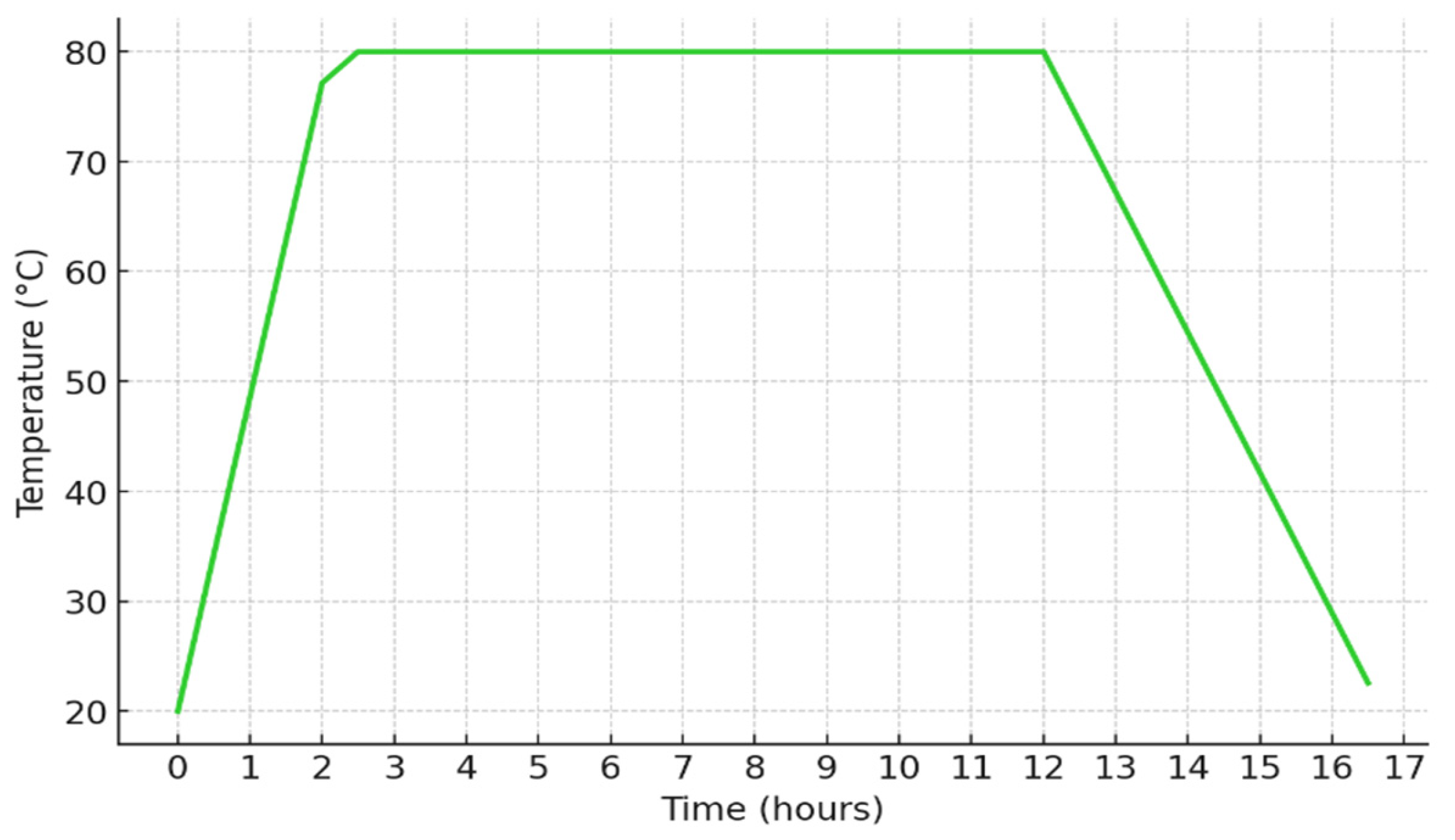
- Cure Cycle: 80 °C for 12 h;
- Areal Weight: 200 g/m2;
- Glass Transition Temperature (Tg): ~130 °C;
- Ultimate Tensile Strength: 2900 MPa;
- Modulus of Elasticity: 150 GPa.
2.4. Description of the CNC Machine Used for Milling the Corian Molds
2.5. Measuring Equipment and Standards
- Surface roughness tester used to assess surface finish—ISR-C300 INSIZE (Suzhou, China);
- Hardness tester used for measuring surface hardness—ORION D600. Hardness measuring techniques were conducted according to the ASTM D785-08(2015) Standard Test Method for Rockwell Hardness of Plastics and Electrical Insulating Materials; [43]
- DriveAFM Nanosurf microscope (Liestal, Switzerland).
2.6. Evaluation of Milling Parameters via Taguchi Method
- Spindle Speed (RPM): 2000, 4000, 6000;
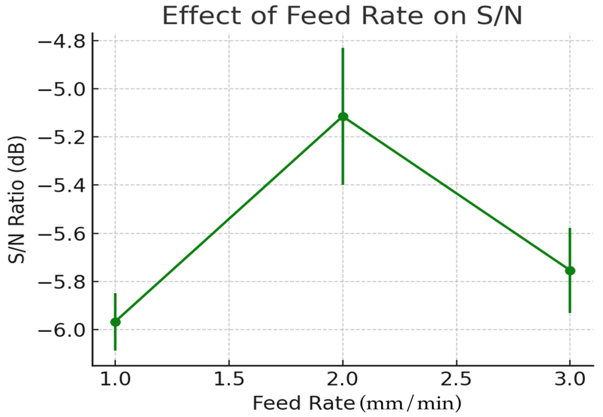
- Feed Rate (mm/min): 500, 1000, 1500;
- Depth of Cut (mm): 0.5, 1.0, 1.5;
- Tool Type: HSS.
3. Results
3.1. Machining and Evaluation
3.1.1. Machining Parameters
3.1.2. Experimental Study and Data Analysis
- Spindle speed: 12,000 RPM;
- Feed rate: 1600 mm/min;
- Depth of cut: 0.5 mm [52].
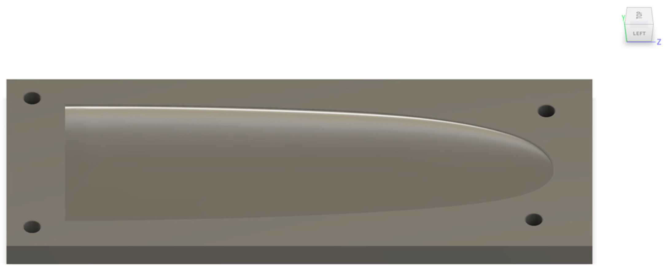
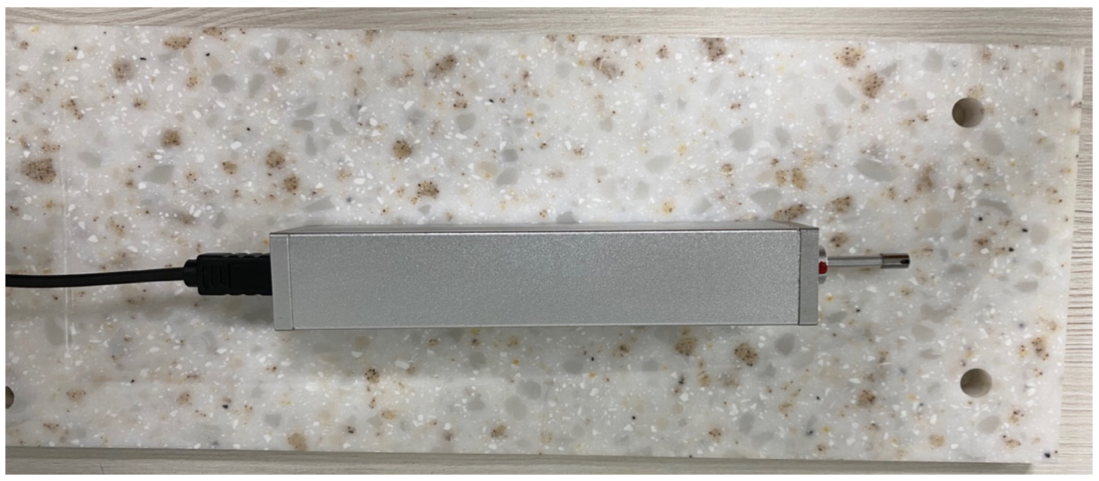
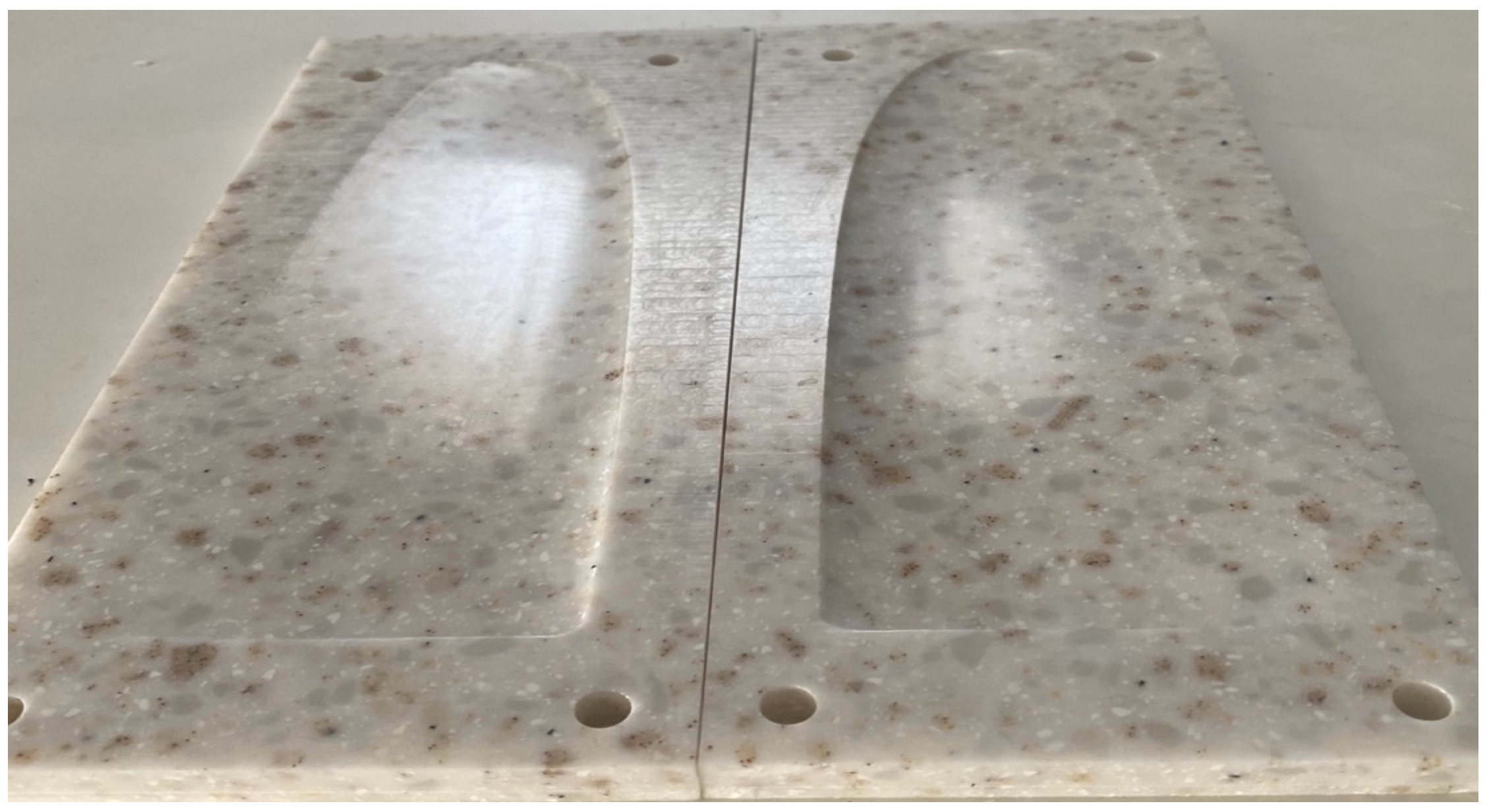
4. Mold Manufacturing
5. Laminate Manufacturing in the Corian Mold
5.1. Preparation and Layup Process
5.2. Laminating
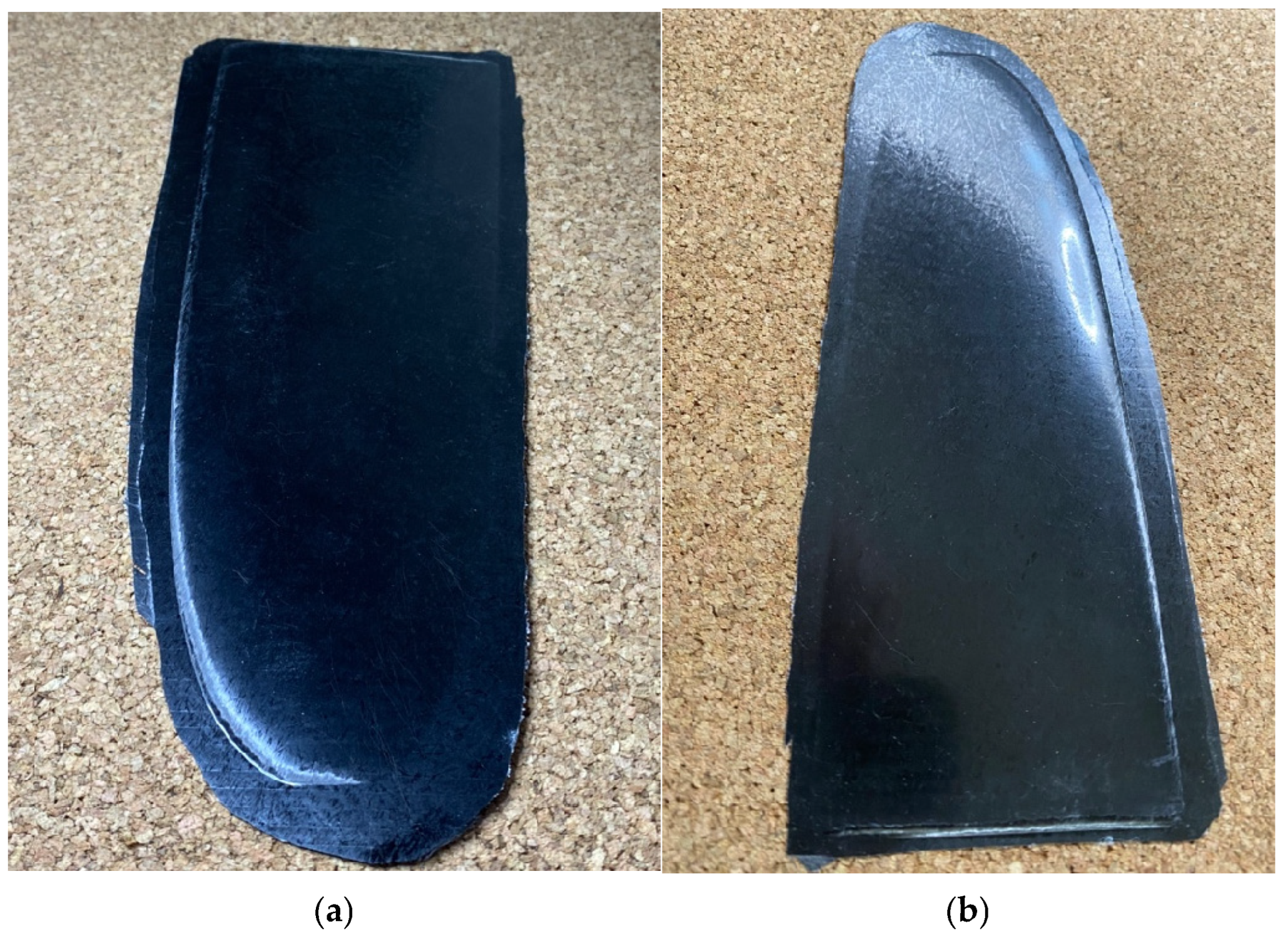
5.3. Final Part Inspection
6. Conclusions
Author Contributions
Funding
Data Availability Statement
Conflicts of Interest
References
- Chardon, G.; Chanal, H.; Duc, E.; Garnier, T. Study of surface finish of fiber-reinforced composite molds. Proc. Inst. Mech. Eng. Part B 2015, 231, 576–587. [Google Scholar] [CrossRef]
- Fu, Y.; Yao, X. A review on manufacturing defects and their detection of fiber reinforced resin matrix composites. Compos. Part C Open Access 2022, 8, 100276. [Google Scholar] [CrossRef]
- Erik, K.; Daniel, S.; Christian, H. Process distortions in prepreg manufacturing—An experimental study on CFRP L-profiles. Compos. Struct. 2013, 106, 615–625. [Google Scholar] [CrossRef]
- Rodriguez-Garcia, V.; Gomez, J.; Cristiano, F.; Gude, M.R. Industrial Manufacturing and Characterization of Multiscale CFRP Laminates Made from Prepregs Containing Graphene-Related Materials. Materials 2020, 13, 3303. [Google Scholar] [CrossRef]
- Baran, I.; Cinar, K.; Ersoy, N.; Akkerman, R.; Hattel, J.H. A review on the mechanical modeling of composite manufacturing processes. Arch. Computat. Methods Eng. 2017, 24, 365–395. [Google Scholar] [CrossRef]
- van-de-Werken, N.; Tekinalp, H.; Khanbolouki, P.; Ozcan, S.; Williams, A.; Tehrani, M. Additively manufactured carbon fiber-reinforced composites: State of the art and perspective. Addit. Manuf. 2020, 31, 100962. [Google Scholar] [CrossRef]
- Li, X.; Shonkwiler, S.; McMains, S. Detection of resin-rich areas for statistical analysis of fiber-reinforced polymer composites. Compos. Part B Eng. 2021, 225, 109252. [Google Scholar] [CrossRef]
- Al-Shawk, A.; Tanabi, H.; Sabuncuoglu, B. Investigation of stress distributions in the resin rich region and failure behavior in glass fiber composites with microvascular channels under tensile loading. Compos. Struct. 2018, 192, 101–114. [Google Scholar] [CrossRef]
- Huang, F.; Pang, X.; Zhu, F.; Zhang, S.; Fan, Z.; Chen, X. Transverse mechanical properties of unidirectional FRP including resin-rich areas. Comput. Mater. Sci. 2021, 198, 110701. [Google Scholar] [CrossRef]
- Shabanijafroudi, N.; Ganesan, R. A new methodology for buckling, postbuckling and delamination growth behavior of composite laminates with delamination. Compos. Struct. 2021, 268, 113951. [Google Scholar] [CrossRef]
- Chukov, D.; Nematulloev, S.; Torokhov, V.; Stepashkin, A.; Sherif, G.; Tcherdyntsev, V. Effect of carbon fiber surface modification on their interfacial interaction with polysulfone. Results Phys. 2019, 15, 102634. [Google Scholar] [CrossRef]
- Léonard, F.; Stein, J.; Soutis, C.; Withers, P. The quantification of impact damage distribution in composite laminates by analysis of X-ray computed tomograms. Compos. Sci. Technol. 2017, 152, 139–148. [Google Scholar] [CrossRef]
- Smith, J.; Johnson, R.; Williams, T. Optimizing machining parameters for polymer composite materials to enhance surface integrity. J. Compos. Mater. 2018, 52, 1011–1024. [Google Scholar]
- Zhang, Y.; Li, X. The impact of process parameters on tool wear and surface finish in thermoplastic composites. Mater. Process. Technol. 2020, 276, 105–113. [Google Scholar]
- Nasir, M.; Wang, Z.; Kumar, P. Investigation of machining strategies for polymer matrix composites. J. Manuf. Sci. Eng. 2015, 137, 031004. [Google Scholar]
- Lee, S.; Choi, J.; Park, H. Effect of cutting parameters on surface quality in milling of polymer composites: An experimental study. Compos. Part B Eng. 2019, 162, 80–89. [Google Scholar]
- Zhang, J.; Li, H.; Wang, Y. Artificial intelligence-assisted optimization of CNC milling parameters for high-efficiency machining of polymer composites. J. Manuf. Process. 2020, 56, 545–552. [Google Scholar]
- Patel, D.; Shah, R.; Desai, S. Advancements in additive manufacturing for composite mold production. Addit. Manuf. 2021, 36, 101532. [Google Scholar]
- Anderson, P. Advanced Hardness Testing Techniques. Mater. Sci. J. 2018, 35, 89–102. [Google Scholar]
- Brown, D.; Miller, T. Comparison of Aluminum and Polymeric Mold Surfaces in Composite Manufacturing. Compos. Res. 2017, 12, 78–95. [Google Scholar]
- Chen, Y.; Patel, K. Effects of Machining Parameters on Polymeric Molds for CFRP Laminates. J. Adv. Manuf. 2020, 28, 140–158. [Google Scholar]
- Ahmad, R.; Shahar, N.; Ghazali, M.J. Surface roughness and tool wear evaluation in high-speed CNC milling of glass fiber reinforced polymer composites. Procedia Manuf. 2020, 51, 379–386. [Google Scholar] [CrossRef]
- DuPont Corian Documentation. Available online: https://www.corian.com/-documentation (accessed on 10 February 2025).
- Roy, R.K. A Primer on the Taguchi Method, 2nd ed.; Society of Manufacturing Engineers (SME): Southfield, MI, USA, 2010. [Google Scholar]
- Zitoune, R.; El Mansori, M.; Krishnaraj, V. Tribological analysis of drilling CFRP/Aluminum stacks. Wear 2016, 376–377, 302–312. [Google Scholar]
- Wang, D.; Chou, T.W. Processing and properties of ceramic composite materials. Compos. Part A Appl. Sci. Manuf. 2018, 109, 170–182. [Google Scholar] [CrossRef]
- Stokes-Griffin, C.M.; Compston, P. The effect of processing temperature and pressure on the consolidation of PEEK/carbon fiber laminates. Compos. Part A Appl. Sci. Manuf. 2018, 113, 107–114. [Google Scholar] [CrossRef]
- Jackson, T.; Mahon, J. Machining performance of acrylic solid surfaces for mold manufacturing. J. Mater. Process. Technol. 2019, 269, 66–73. [Google Scholar]
- Johnson, T.; Lee, R.; Kim, P. Machining and application of Corian for mold production. Compos. Sci. Technol. 2019, 184, 107756. [Google Scholar] [CrossRef]
- Brown, R.; Martens, M.; Fischer, A. Effect of mold material thermal conductivity on the performance of CFRP composites during curing. J. Thermoplast. Compos. Mater. 2020, 33, 210–225. [Google Scholar]
- Smith, J.; Adams, R. Surface Roughness Analysis in Composite Tooling. Compos. Mater. J. 2016, 33, 44–61. [Google Scholar]
- Taguchi, G. System of Experimental Design: Engineering Methods to Optimize Quality and Minimize Costs; UNIPUB/Kraus International: White Plains, NY, USA, 1987. [Google Scholar]
- Huang, H.; Zhang, M.; Lee, J. CNC Milling of Composite Materials: Surface Quality and Tool Wear. Int. J. Adv. Manuf. Technol. 2016, 87, 123–135. [Google Scholar]
- Jones, P.; Lee, S. Surface Characterization of Mold Materials for Composite Tooling. Compos. Sci. Technol. 2019, 172, 85–99. [Google Scholar]
- Kumar, S.; Zhang, L.; Liu, Y. Microstructural Analysis of Composite Tooling Materials. J. Manuf. Sci. Eng. 2019, 141, 091014. [Google Scholar]
- Lee, M.; Kim, H.; Lee, J. Measuring Shore D Hardness of Composites for Mold Quality Assessment. J. Compos. Mater. 2020, 54, 112–123. [Google Scholar]
- Mason, L.; Patel, K. The Role of Prepreg CFRP in Aerospace and Automotive Applications. Compos. Technol. Rev. 2017, 25, 62–77. [Google Scholar]
- Prepreg Material Datasheet. Available online: https://www.imatec.it/wp-content/uploads/2016/05/M35_4_eu.pdf (accessed on 12 February 2025).
- Miller, P.; Johnson, T. Surface Roughness Testing and Analysis: A Practical Approach. J. Surf. Eng. 2015, 41, 12–21. [Google Scholar]
- Montgomery, D.C. Design and Analysis of Experiments, 8th ed.; John Wiley & Sons: Hoboken, NJ, USA, 2012. [Google Scholar]
- Ross, P.J. Taguchi Techniques for Quality Engineering; McGraw-Hill: New York, NY, USA, 1988. [Google Scholar]
- Phadke, M.S. Quality Engineering Using Robust Design; Prentice Hall: Englewood Cliffs, NJ, USA, 1989. [Google Scholar]
- ASTM D785-08; Standard Test Method for Rockwell Hardness of Plastics and Electrical Insulating Materials. ASTM: West Conshohocken, PA, USA, 2015.
- Antony, J. A systematic methodology for the design of experiments. Work Study 2003, 52, 24–28. [Google Scholar]
- Hasdiansah, H.; Yaqin, R.I.; Pristiansyah, P.; Umar, M.L.; Priyambodo, B.H. FDM 3D Printing Parameter Optimization Using Taguchi Approach on Surface Roughness of Thermoplastic Polyurethane (TPU) Parts. Int. J. Interact. Des. Manuf. (IJIDeM) 2023, 17, 829–842. [Google Scholar] [CrossRef]
- Dettmer, T.; Taboada, H.A. Application of Taguchi method for multi-objective optimization in thermoplastic welding. J. Manuf. Process. 2021, 62, 668–677. [Google Scholar] [CrossRef]
- Patel, R. Vacuum Bagging and Prepreg Lamination in Composite Manufacturing. Adv. Compos. Manuf. J. 2019, 5, 34–47. [Google Scholar]
- Tepper, L. Advanced Composite Materials: Prepregs and Curing Techniques. Compos. Manuf. Technol. 2020, 12, 89–101. [Google Scholar]
- Byrne, D.M.; Taguchi, S. The Taguchi approach to parameter design. Qual. Prog. 1987, 20, 19–26. [Google Scholar]
- Patel, D.H.; Patni, V.N. An investigation effect of machining parameters on CNC router. Int. J. Eng. Dev. Res. (IJEDR) 2014, 2, 1497–1503. [Google Scholar]
- DuPont Corian Technical Bulletin. Available online: https://casf.com.au/wp-content/uploads/2022/01/Performance_Properties_of_Corian.pdf (accessed on 21 February 2025).
- Bogue, A.J.; Brown, A.J.; Doughty, C.J.; Dunn, C.J. Manufacturing of a Carbon Fiber Part with Complex Geometry; Senior Project; California Polytechnic State University: San Luis Obispo, CA, USA, 2012; Available online: https://digitalcommons.calpoly.edu/mesp/414 (accessed on 21 February 2025).
- Garcia, L.; Roberts, M. Optimization of CNC Milling for Non-Metallic Mold Materials. Manuf. Sci. Eng. 2017, 20, 213–229. [Google Scholar]


| Factor | Level 1 | Level 2 | Level 3 |
|---|---|---|---|
| Spindle speed (RPM) | 4000 | 8000 | 12,000 |
| Feed rate (mm/min) | 800 | 1600 | 2500 |
| Depth of cut (mm) | 0.5 | 0.75 | 1.5 |
| Tool | HSS | HSS | HSS |
| Experiment | Spindle Speed [RPM] | Feed Rate [mm/min] | Depth of cut [mm] | Surface Roughness [µm] | S/N Ratio |
|---|---|---|---|---|---|
| 1 | 4000 | 800 | 0.5 | 2.1 | −6.44438 |
| 2 | 4000 | 1600 | 0.75 | 1.8 | −5.10545 |
| 3 | 4000 | 2000 | 1.5 | 2.4 | −7.60422 |
| 4 | 8000 | 800 | 0.5 | 1.7 | −4.60897 |
| 5 | 8000 | 1600 | 0.75 | 2.5 | −7.95880 |
| 6 | 8000 | 2000 | 1.5 | 1.6 | −4.08239 |
| 7 | 12,000 | 800 | 0.5 | 2.2 | −6.84845 |
| 8 | 12,000 | 1600 | 0.75 | 1.3 | −2.27886 |
| 9 | 12,000 | 2000 | 1.5 | 1.9 | −5.57507 |
| Factor | p Value | F Value | Impact on Surface Roughness |
|---|---|---|---|
| Depth of cut | 0.216 | 3.62 | High impact |
| Spindle speed | 0.628 | 0.59 | Low impact |
| Feed rate | 0.887 | 0.12 | Negligible |
| Parameter | Control Group Settings | Optimized Settings |
|---|---|---|
| Depth of cut [mm] | 1.5 | 0.5 |
| Spindle speed [RPM] | 10,000 | 12,000 |
| Feed rate [mm/min] | 2000 | 1600 |
| Roughness [µm] | 2.9 | 1.3 |
| Tool Surface State | Measured Roughness [µm] |
|---|---|
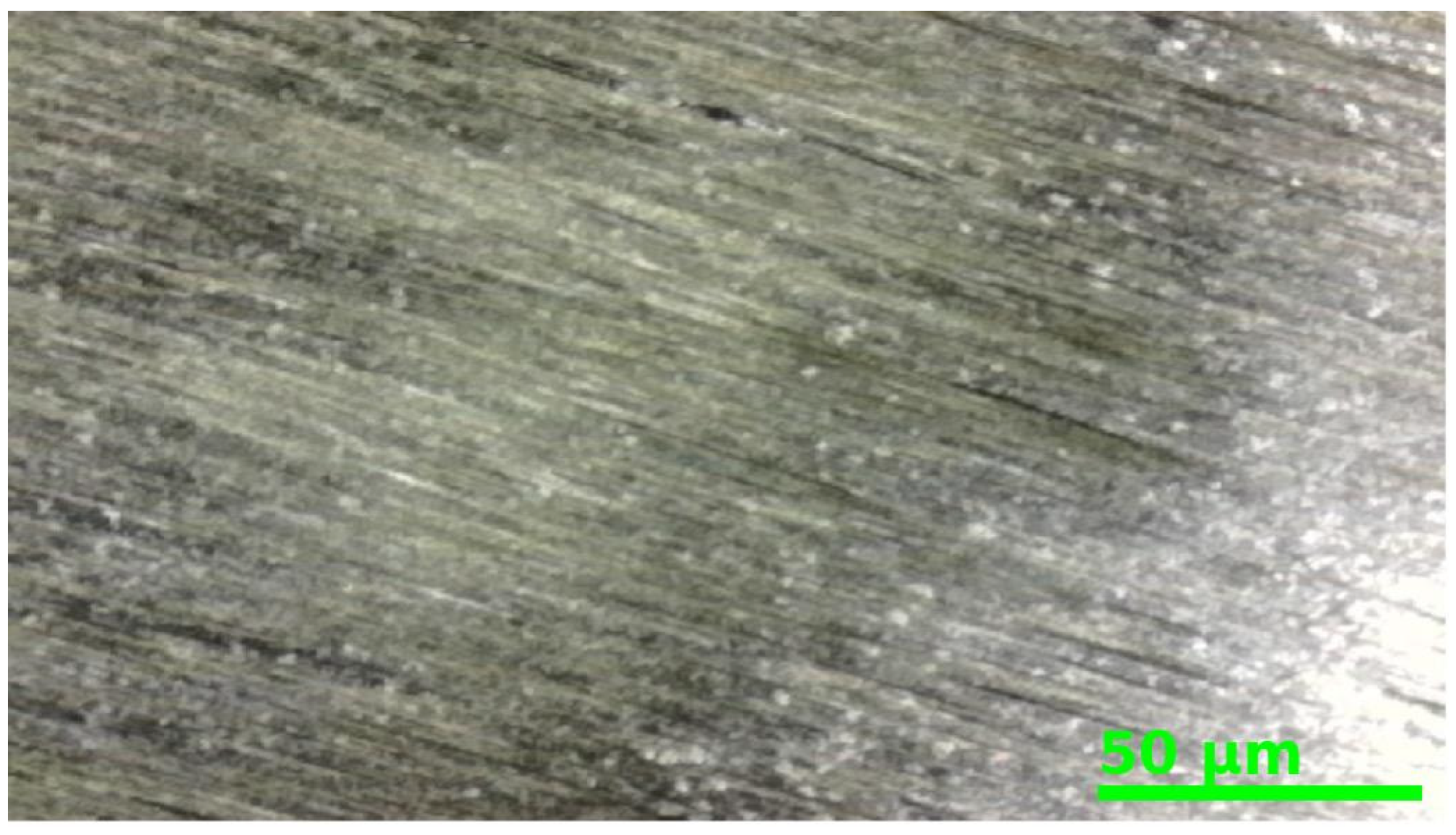
| Raw milled | 1.632 |
| Buffed and polished | 0.235 |
| Surface Temperature [°C] | Surface Measured Hardness [HRM] |
|---|---|
| 20 | 97.31 |
| 50 | 64.46 |
| 80 | 62.07 |
| 120 | 40.66 |
Disclaimer/Publisher’s Note: The statements, opinions and data contained in all publications are solely those of the individual author(s) and contributor(s) and not of MDPI and/or the editor(s). MDPI and/or the editor(s) disclaim responsibility for any injury to people or property resulting from any ideas, methods, instructions or products referred to in the content. |
© 2025 by the authors. Licensee MDPI, Basel, Switzerland. This article is an open access article distributed under the terms and conditions of the Creative Commons Attribution (CC BY) license (https://creativecommons.org/licenses/by/4.0/).
Share and Cite
Părpăriță, M.; Bere, P.; Cioază, M. A Novel Method for Manufacturing Molds for CFRP Prepreg Lamination Using Polymeric Acrylic Resin–Aluminum Trihydrate. J. Manuf. Mater. Process. 2025, 9, 195. https://doi.org/10.3390/jmmp9060195
Părpăriță M, Bere P, Cioază M. A Novel Method for Manufacturing Molds for CFRP Prepreg Lamination Using Polymeric Acrylic Resin–Aluminum Trihydrate. Journal of Manufacturing and Materials Processing. 2025; 9(6):195. https://doi.org/10.3390/jmmp9060195
Chicago/Turabian StylePărpăriță, Mihai, Paul Bere, and Mircea Cioază. 2025. "A Novel Method for Manufacturing Molds for CFRP Prepreg Lamination Using Polymeric Acrylic Resin–Aluminum Trihydrate" Journal of Manufacturing and Materials Processing 9, no. 6: 195. https://doi.org/10.3390/jmmp9060195
APA StylePărpăriță, M., Bere, P., & Cioază, M. (2025). A Novel Method for Manufacturing Molds for CFRP Prepreg Lamination Using Polymeric Acrylic Resin–Aluminum Trihydrate. Journal of Manufacturing and Materials Processing, 9(6), 195. https://doi.org/10.3390/jmmp9060195