Article

In-Depth Thermal Analysis of Different Pin Configurations in Friction Stir Spot Welding of Similar and Dissimilar Alloys

Mechanical Department, Engineering College, University of Basrah, Basrah 61004, Iraq
*
Author to whom correspondence should be addressed.
J. Manuf. Mater. Process. 2025, 9(6), 184; https://doi.org/10.3390/jmmp9060184
Submission received: 1 April 2025 / Revised: 16 May 2025 / Accepted: 30 May 2025 / Published: 1 June 2025

Abstract

Over the past decade, friction stir spot welding (FSSW) has gained increasing attention, making it a competitor to conventional welding methods such as resistance welding, rivets, and screws. This type of welding is environmentally friendly because it does not require welding tools and is solid-state welding. This study attempts to demonstrate the importance of pin geometry on temperature distribution and joint quality by using threaded and non-threaded pins for similar and dissimilar alloys. To this end, thermal analysis of the welded joints was conducted using real-time monitoring from a thermal camera and an infrared thermometer, in addition to finite element method (FEM) simulations. The thermal analysis showed that the generated temperatures were higher in dissimilar alloys (Al-Cu) than in similar ones (Al-Al), reaching about 350 °C. In addition, dissimilar alloys show more pronounced FSSW stages through extended periods for each plunging, dwelling, and drawing-out time. The FEM simulation results are consistent with those obtained from thermal imaging cameras and infrared thermometers. The dwelling time was influential, as the higher it was, the more heat was generated, which could be close to the melting point, especially in aluminum alloys. This study provides an in-depth experimental and numerical investigation of temperature distribution throughout the welding cycle, utilizing different pin geometries for both similar and dissimilar non-ferrous alloy joints, offering valuable insights for advanced industrial welding applications.

1. Introduction

Aluminum and copper alloys are widely used in the aerospace, automotive, and aviation industries, which require the production of high-strength, fracture- and fatigue-resistant joints. These alloys possess a low melting point, complicating their joining using traditional welding techniques due to flaws manifesting in the weld upon reaching the melting temperature [1,2]. Friction stir welding (FSW) is a solid-state welding process where the temperature generated during the welding process in this method does not reach the melting point of the workpiece. The Welding Institute (TWI) first used this process three decades ago [3]. During the FSW process, two workpieces, usually made of similar or dissimilar metals, are butt-welded [4,5]. After the two workpieces are securely clamped, the welding tool, which consists of a long cylindrical part called the shoulder and a tapered part called the pin, is passed over them. The welding tool moves in two motions: the first is a rotational motion around the tool axis at a high rotational speed, which contributes to generating heat from friction between the welding tool and the workpieces. When the temperature reaches a value that allows the weld to soften (below the melting point of the workpieces), the tool moves transversely along the weld line at an appropriate speed [6]. This motion is sufficient to join the two workpieces, creating a weld with higher strength than conventional fusion welding [7,8].
As a special case of FSW, friction stir spot welding (FSSW) eliminates the need for the tool’s transverse movement [9,10]. As shown in Figure 1, the FSSW process consists of three main stages: plunging, stirring, and retracting [11,12]. The non-consumable tool plunges into the workpieces for connection in the first stage. In the second stage, due to the high speed at which the welding tool rotates, sufficient heat will be generated to plastically soften the area, leading to mixing the materials of the upper and lower plates during a specific time called “dwelling time”. The welding tool moves upwards in the final stage, leaving the two workpieces spot-welded [13,14].
In FSSW, the heat generation during welding depends on the friction between the welding tool and the workpiece, which in turn causes plastic deformation in this area [15]. Studies found that it saves more than 90% of energy and reduces costs by 40% when compared to conventional resistance spot welding (RSW) [16,17]. Studying the heat generated during FSSW is essential because it reflects the relationship between welding process parameters and the weld joint quality formed. Studying the heat distribution during FSSW contributes to a more profound understanding of the metal softening process and subsequent metal flow. Numerous studies have attempted to address this topic; some rely entirely on experiments, others using simulations, and a few trying to combine them. The simulation model developed by Bawagnih et al. [18] relied primarily on the coupled Eulerian–Lagrangian finite element method and experimental validation. Their model showed that the low rotation speed (around 400 rpm) is insufficient to generate the heat to produce highly efficient weld joints. Jaiswal et al. [19] used a cylindrical steel tool to study the temperature distribution of AA6061 aluminum alloy based on changes in rotational tool speed. The study indicated that tool speed significantly influences the heat generated, with the increase steadily increasing as the rotational speed increases. Khalaf et al. [20] conducted an extensive study to investigate the influence of thermomechanical phenomena on high-density polymers when joined using friction stir welding. Their study included the effects of specific heat, thermal conductivity, and viscosity using different shoulder and pin shapes and demonstrated that the cubic pin offered the best performance. Hamzah et al. [21] developed a simulation model to determine the temperature distribution during FSSW at constant rotational tool speeds, supported by experimental results using a K-type thermocouple. The study indicated that a cylindrical pin could provide the best thermal performance compared to other shapes. Al-Sabur et al. [22] showed that real-time monitoring of the FSSW process, especially the axial load, can be crucial in preventing unwanted deformations in the weld zone. It contributes to controlling the generated heat, which can reach 65% of the melting point of AA1230 aluminum alloy at high rotation speeds. Andrade et al. [23] compared the thermal behavior of heat-treated and non-heated-treated aluminum alloys using experimental and simulation models. Their study explored the effect of tool diameter when the tool is pinless and showed that it becomes more pronounced when the tool rotation speed exceeds 600 rpm. Furthermore, each tool diameter can have a threshold temperature, regardless of whether the alloy is heat-treated or unheated. A study by Serier et al. [24] focused on the effect of thermal diffusivity on joint quality, particularly in the heat-affected zone. They found that the heat generated in the weld in the stir zone can approach the metal’s melting point, especially in medium-strength aluminum alloys such as AA 6060-T5. Boopathi et al. [25] developed a simulation model based on CAD modeling and experimental validation to predict heat generation and transfer during the FSSW process. They found that understanding thermal behavior significantly reduced heat-affected zones and improved welding parameters. Studies exploring the heat generated during the FSSW process have not been limited to aluminum alloys but have also extended to other light alloys, such as magnesium alloys [26], and extended to include steel alloys [27].
The ongoing research on the effects of heat generation and its distribution during FSSW processes, particularly in the past three years, clearly demonstrates that the research gap remains significant and that there is an urgent need for more in-depth research. This in-depth research will help the industry better understand the behavior of heat generation and its subsequent impact on the nature of the resulting joint. This study focuses on the thermal analysis of the geometry of the welding pin. It investigates two types of configurations, threaded and non-threaded, and tests two types of joints (similar and dissimilar) through finite element simulations. Experiments validate this simulation by measuring the temperature distribution from thermal cameras focusing on the weld zone.

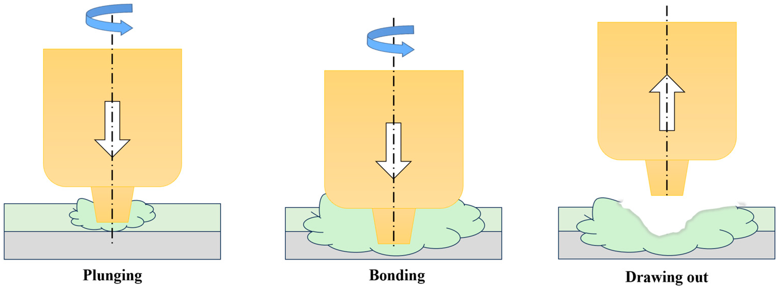
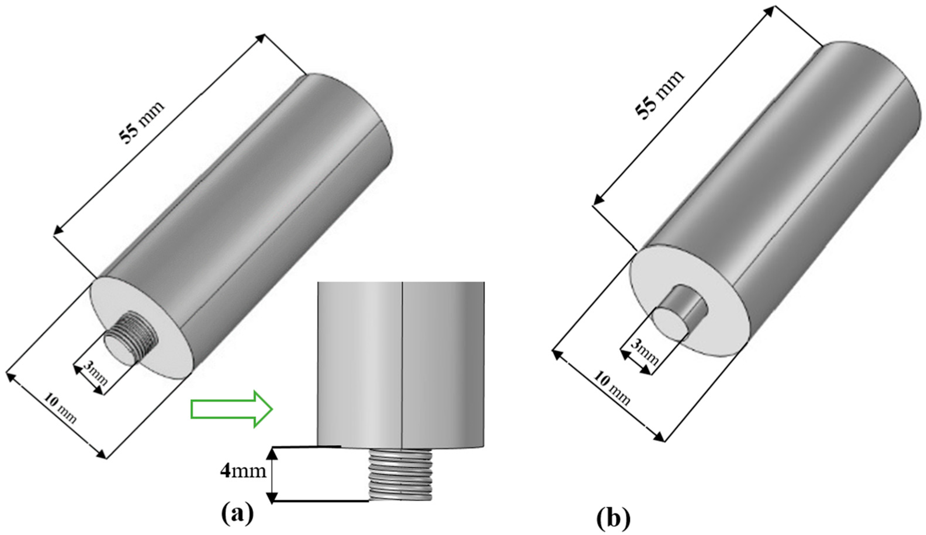
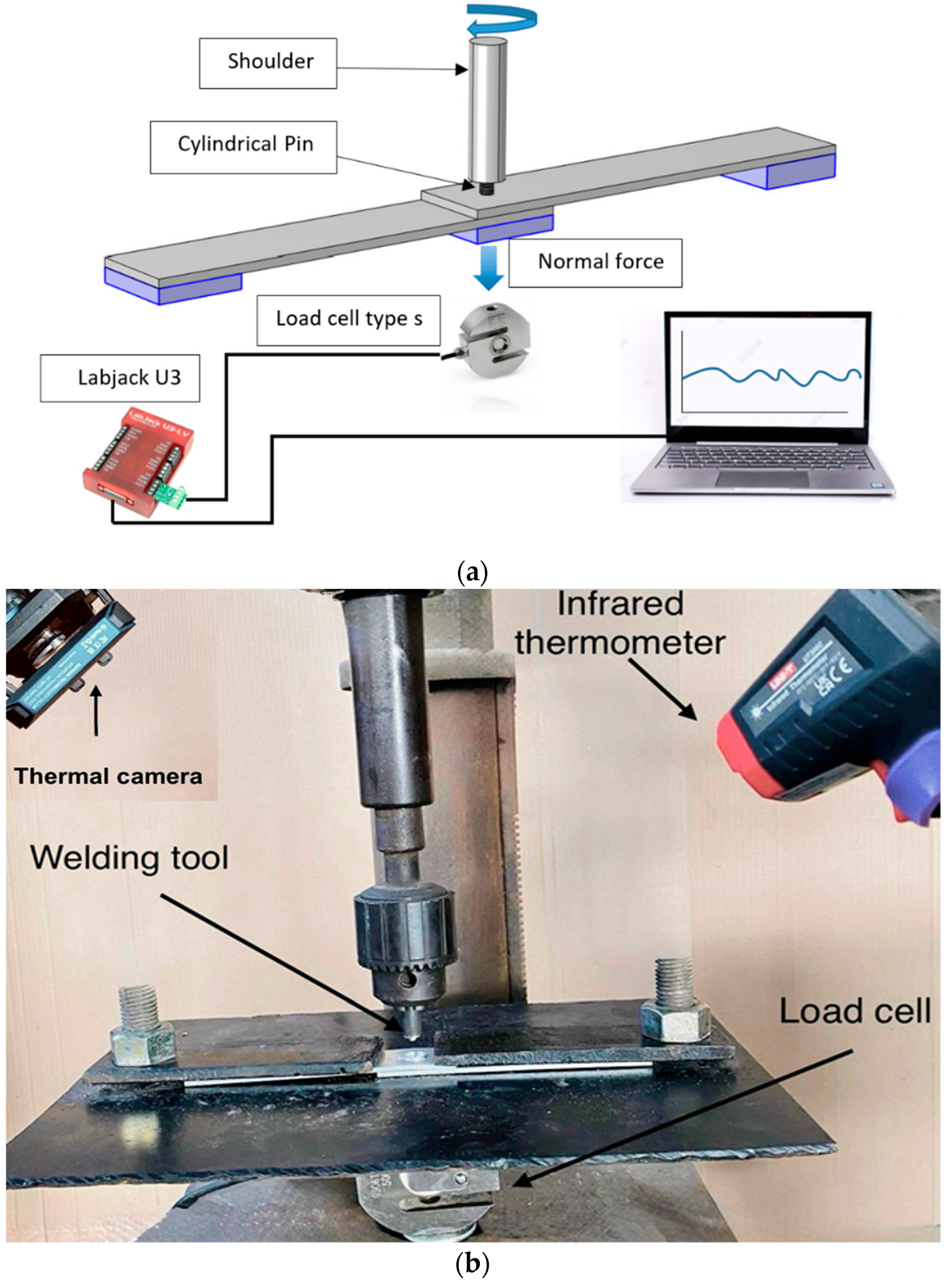
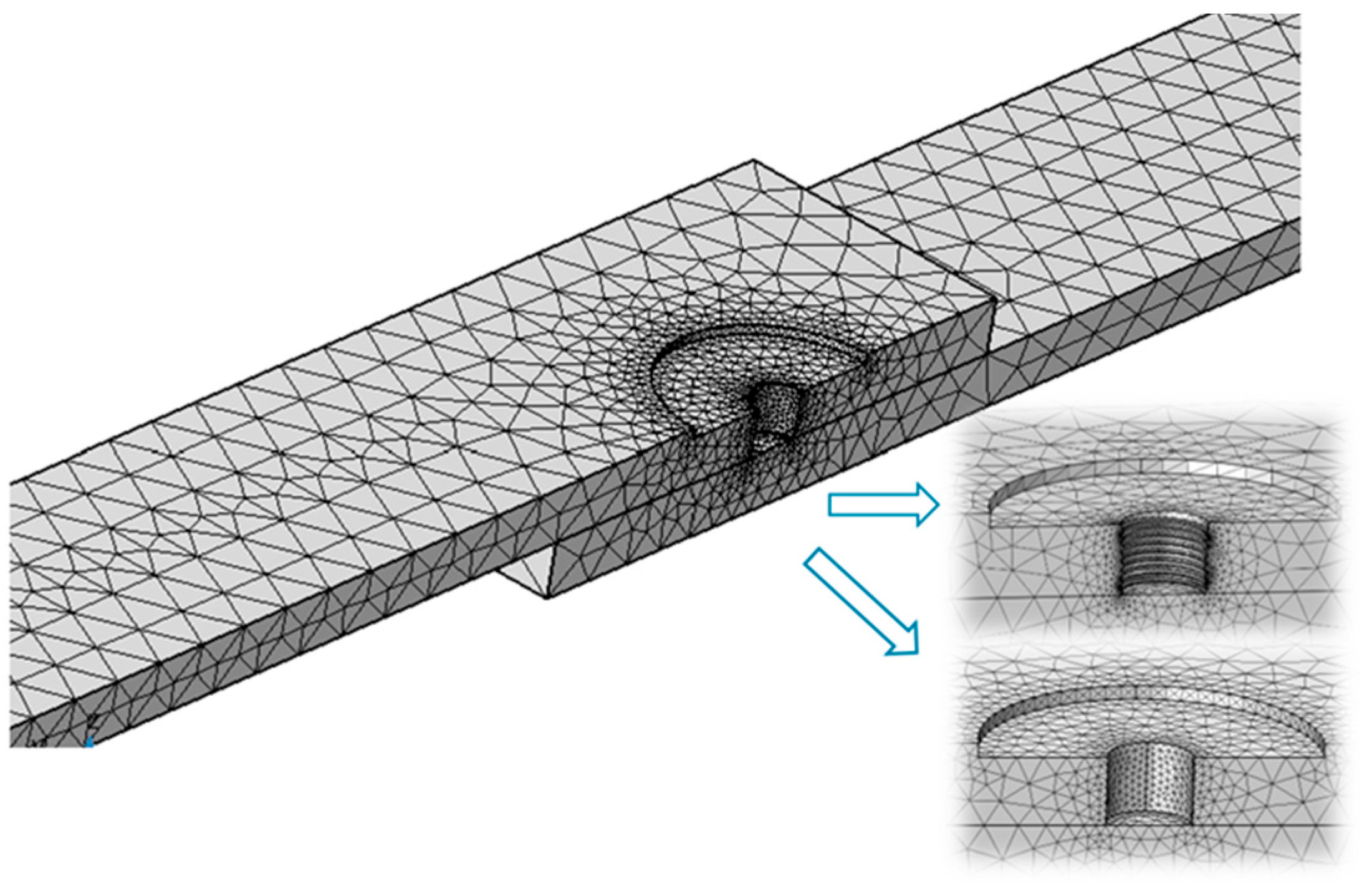
2. Materials and Methods

This study is part of a long-term research project initiated at our university over the past five years, focusing on FSW and FSSW of non-ferrous alloys and polymeric materials. The selection of welding parameters—particularly the tool rotational speeds—was based on a series of experimental investigations previously conducted. A radial drilling machine R915L (Breda, Treviso, Italy) of 40 mm capacity and a table of size 600 mm × 450 mm was used as an FSSW machine. The welding machine provides a wide range of tool rotational speeds, making it suitable for many applications. This study used a constant rotational speed of 1500 rpm in all experiments. To explore the thermal analysis in similar alloys, an aluminum alloy AA 6061 was used, while it was joined to a pure copper alloy (C11000) to investigate the effects on dissimilar alloys. Table 1 shows the chemical compositions of AA 6061 and copper (C11000) as measured using metal analyzers SPECTROPORT PXC01 (AMETEK, Berwyn, PA, USA). Table 2 shows the mechanical properties of both alloys.
The AA 6061 and C1100 specimens were prepared as 150 × 30 × 3 mm in length, width, and thickness, respectively. An FSSW tool made of 1.5% carbon was used. A die steel tool can achieve high hardness wear resistance and thermal stability, generating significant heat due to friction. Thus, the weld quality can be improved, and the tool wear in dissimilar metal welding can also be reduced. The chemical composition of the die steel tool is shown in Table 3. The specific chemical composition of a high-alloy carbon steel containing 12 wt.% chromium and 1 wt.% molybdenum enhanced the tool’s resistance to wear and corrosion, particularly under elevated thermal and mechanical loads.
The cylindrical pin configurations were prepared to be threaded and non-threaded, as shown in Figure 2a,b. The tool used in the study consisted of a shoulder with a diameter of 10 mm and a length of 55 mm. The pin attached to the shoulder had a diameter of 3 mm and a length of 4 mm.
The specimens were prepared in similar and dissimilar alloys as a lap joint configuration. A load cell SS300 (Sewha CNM Co., Bucheon-si, Republic of Korea) was used to monitor the axial load during the FSSW process. This stainless steel load cell has a capacity of 50 kgf/tf and a combined error of 0.03%. It was connected to an analog-to-digital converter U3-LV (LabJack, Denver, CO, USA), which interfaced with LabVIEW software for real-time data acquisition and monitoring. A special rig was prepared to fix the specimens and other parts during the FSSW process. A thermal camera and infrared thermometer were used to analyze the thermal behavior. The TC002 thermal imaging camera (TOPDON, Rockaway, NJ, USA) compatible with smartphones, monitors the temperatures of all regions during the process. The ultra-high resolution of 256 × 192 and 40 mk high heat sensitivity provided the required characteristics for sensitive real-time temperature monitoring during the FSSW. Besides the thermal camera, a high-temperature infrared thermometer (Fluke, Everett, WA, USA) is used to monitor the maximum temperature on the contact point between the pin and the specimen. Figure 3 shows the main tools and equipment and the specimens’ configuration.
For each welding condition, three experimental trials were conducted to ensure the repeatability and reliability of the temperature measurements. The peak temperatures were recorded using thermal imaging and infrared thermometry, and the mean values from each set of tests were used for comparison with the FEM simulations.
A 3D dimension’s finite element transient nonlinear heat transfer model was developed to determine the temperature distribution during the FSSW. In this study, COMSOL Multiphysics version 6.2 was used with several assumptions. These include that both AA 6061 and C1100 are homogeneous and isotropic, that the FSSW process does not melt anything, that there is not much heat transfer from the workpiece to the workpiece fixture, and that the FSSW tool stays rigid and does not change shape. In the numerical simulation of FSSW, the choice of mesh type and the number of mesh nodes play a critical role in determining the results’ accuracy, stability, and computational efficiency [29,30]. The surface emissivity used during the experimental measurements with the TC002 thermal imaging camera (TOPDON, Rockaway, NJ, USA) was 0.3, consistent with the value specified in Table 4 and used in the COMSOL Multiphysics 6.2 simulation. This emissivity setting was applied based on the welded region’s surface characteristics for AA6061 and C1100 materials, which were considered homogeneous and isotropic in the simulation. The mesh type—structured, unstructured, or adaptive—must be chosen to effectively represent the geometry and process dynamics [31]. Conversely, FSW and FSSW studies have shown that the number of nodes and mesh density directly impact the accuracy of temperature fields, material flow, and stress distribution [32,33]. A mesh sensitivity analysis was conducted to ensure the reliability of the simulation results. Three mesh densities—coarse (~45,000 elements), medium (~92,000 elements), and fine (~160,000 elements)—were applied and evaluated in terms of the resulting temperature distribution in the weld zone. The comparison showed that the peak temperature varied by less than 2% between the medium and fine meshes, indicating that further refinement had minimal effect on the accuracy of the thermal predictions while significantly increasing computation time. So, a medium-density mesh with 92,000 elements, including triangular and tetrahedral elements, was chosen because it offers a good mix of accuracy and calculation speed. Due to considerations related to simulation execution time and the limited impact of heat generation on areas far from the weld, a finer mesh was used only in the weld zone. In contrast, a normal mesh was used for the rest of the area as shown in Figure 4. The process parameters which are used in the simulation are listed in Table 4.
Experimental temperature measurements served to validate the FEM simulation, utilizing two distinct tools. During the FSW process, a thermal camera recorded the real-time temperature distribution along the whole weld line, providing a comprehensive thermal profile of the heat-affected zone.
Additionally, an infrared (IR) thermometer measured the temperature at the critical tool pin tip to understand peak temperatures and thermal input. When results from both the thermal camera and IR thermometer were compared with the FEM simulation outputs, a strong correlation emerged. This confirms the FEM model’s accuracy in predicting the thermal behavior of the welding process, and this dual-method validation reinforces the numerical model’s reliability.

3. Results and Discussions

In this section, the effect of pin configuration on the thermal analysis of similar and dissimilar alloys will be studied through the results obtained from experiments and compared with simulation results, including the temperature distribution in the weld zone and the maximum temperatures obtained. Then, the effect of pin configuration temperature profiles will be studied, examining the temperatures in the weld zone throughout the FSSW process until it cools below room temperature. Finally, the effect of pin configuration on the joint shape will be discussed.

3.1. Effect of Pin Configuration on Thermal Analysis

This study used a 1500 rpm tool rotational speed, a plunging depth of 4 mm, and a plunging rate of 15 mm/min. The dwelling time is selected as 4, 6, and 8 s. The following sections discuss the effect of pin configuration on the thermal analysis of similar and dissimilar alloys based on experimental results compared to the FEM results. Then, the impact of pin configuration on the welding region shapes will be discussed.

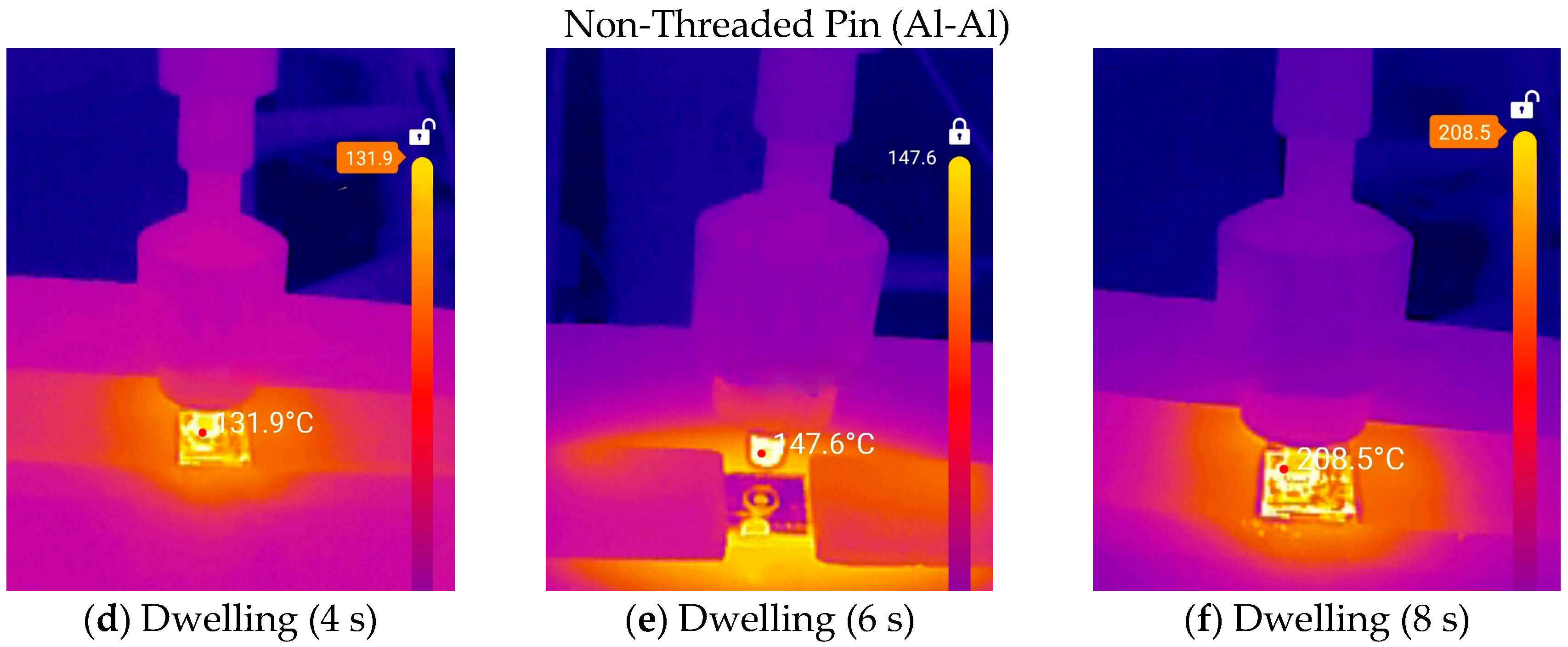
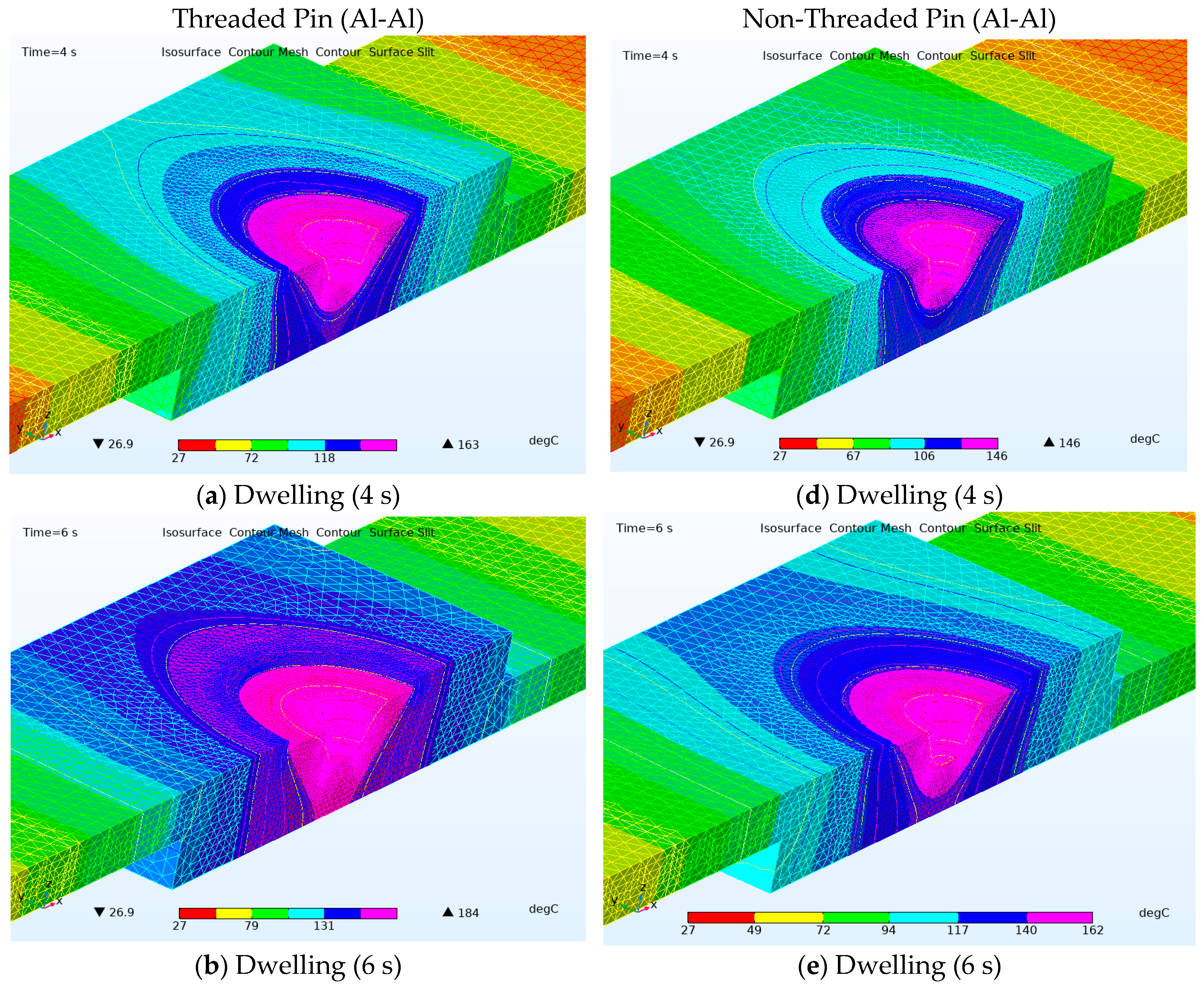
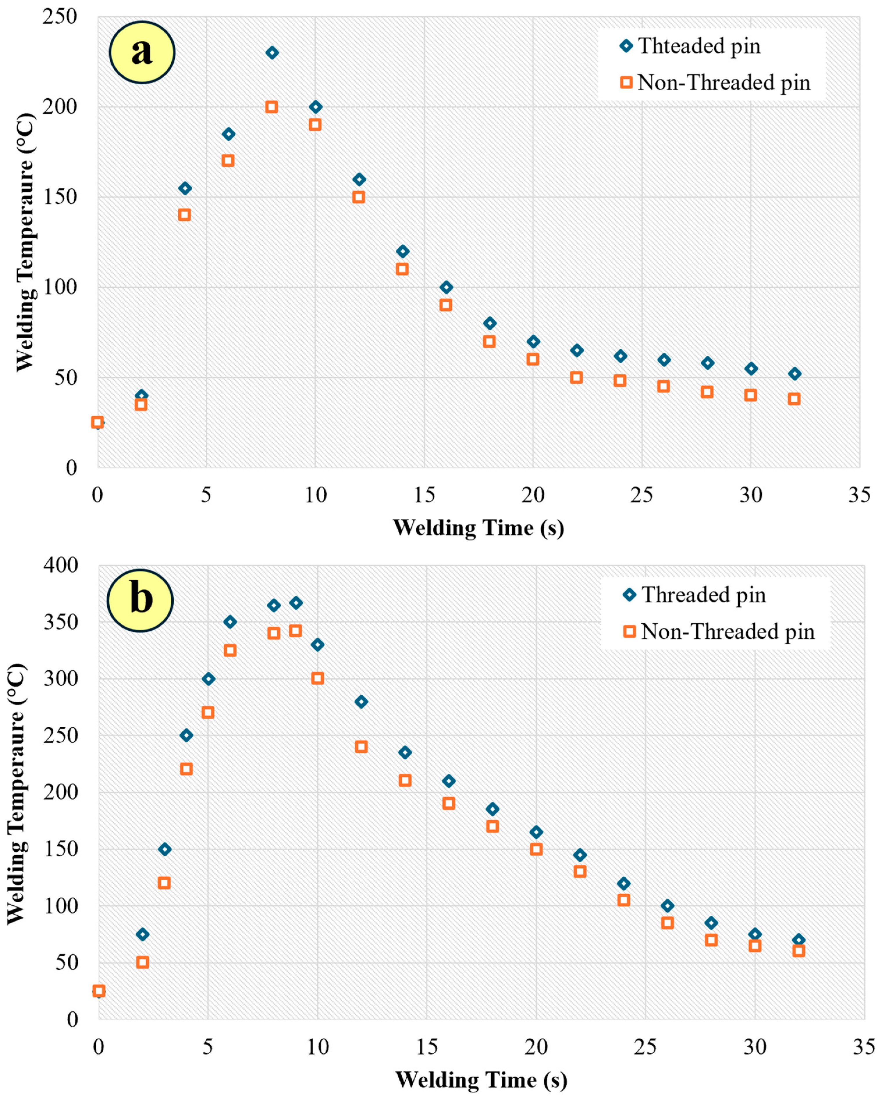
3.1.1. Thermal Analysis in Similar Alloys

The results obtained from the thermal camera and the finite elements reveal that the maximum temperature during FSSW is higher when using the threaded pin than the non-threaded pin, as shown in Figure 5 and Figure 6. The relative difference in maximum temperatures between the two types of pins used for welding similar metals can be explained by increased friction and heat generation. The threading in the pin increases plastic deformation due to its increased contact area and facilitates material movement, thereby improving the temperature distribution within the weld zone [34,35]. Moreover, the threaded pin can create a mini-closed environment that causes thermal accumulation. The non-threaded pin lacks these advantages because it relies on a smaller contact area, generating relatively less heat [36,37].
As the dwelling time increases, the tool remains in contact with the material for longer, allowing continuous frictional heat generation. The longer the tool stays in place, the more heat accumulates, leading to a higher maximum temperature. With a longer dwelling time, the generated heat has more time to penetrate deeper into the material [38]. In short dwelling times (e.g., 4 s), the heat generated may dissipate into the surrounding material, limiting the peak temperature [39]. With longer dwelling times, heat builds up faster than it dissipates, leading to higher maximum temperatures. The heat generated is proportional to the duration of contact, leading to higher temperatures as dwelling time increases. As the dwelling time increases from 4 to 8 s, the maximum temperature increases for threaded and non-threaded pins. The maximum temperature obtained from the threaded pin was 219 °C (experimentally) at maximum dwelling time (8 s) for the threaded pin corresponding with 208 °C non-threaded pin, as shown in Table 5. The temperature increase was due to extended frictional heating, improved heat penetration, and enhanced material plasticization. As the material softens and becomes more plastic, the resistance to deformation decreases, which can lead to increased heat generation due to viscous dissipation. In addition, this increase can be explained by looking at phase changes, grain composition, and grain boundaries. As the temperature increases, some materials may undergo phase transformations (e.g., recrystallization or grain of threaded and non-threaded pins, but threaded pins will generate more heat overall due to their design and material stirring capabilities. Figure 5a–f indicates the temperature distribution map obtained from the thermal camera, while Figure 6a–f explores the temperature distribution from FEM simulation.

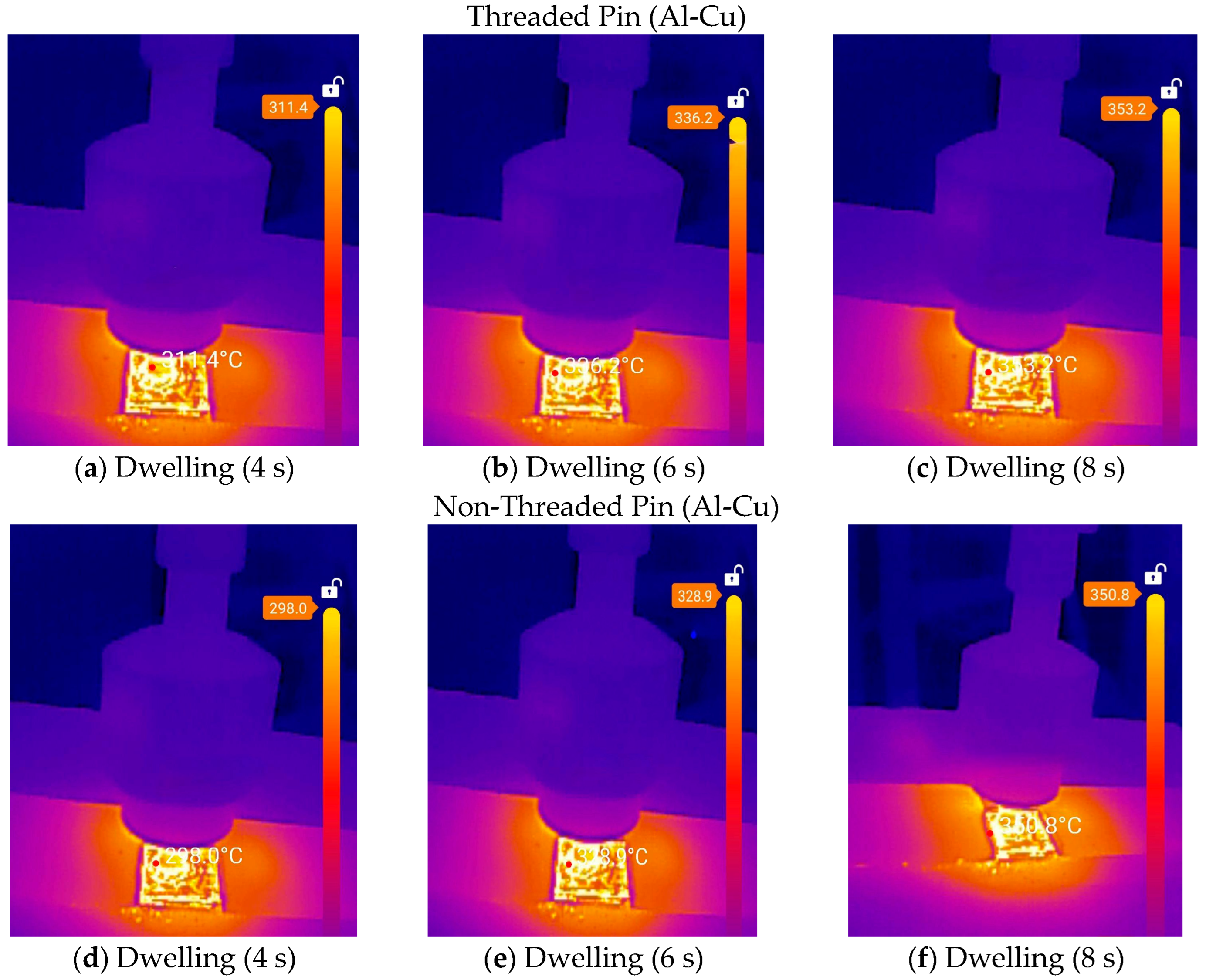
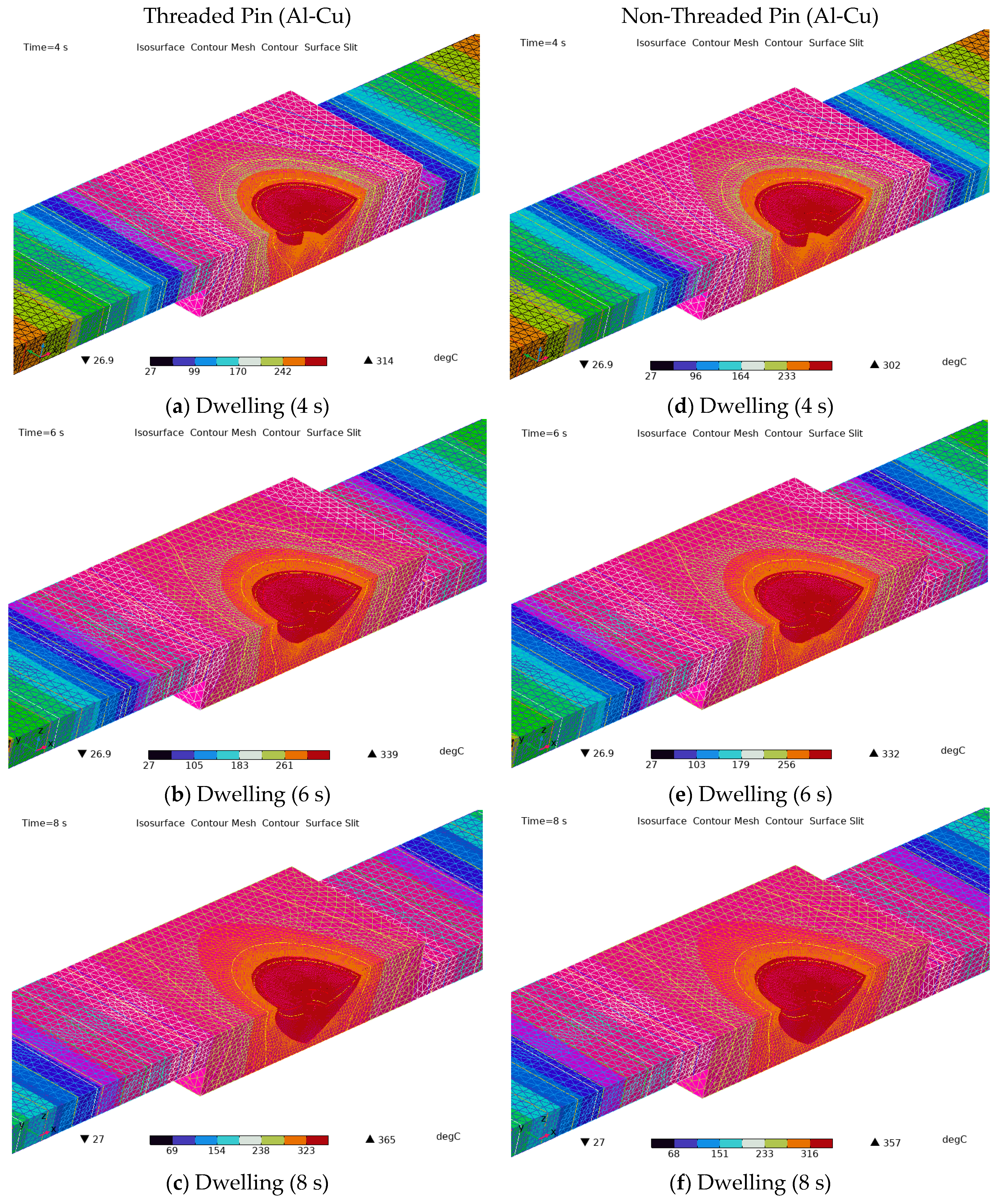
3.1.2. Thermal Analysis in Dissimilar Alloys

The significant difference between the melting points of copper and aluminum has caused a problem because copper’s melting point is about twice as high. As the aluminum entirely melts into a liquid state, copper remains solid, and the liquid aluminum tends to float on the surface of copper [10,40]. Such obstacles in traditional welding methods make FSW and FSSW unique and reliable solutions for welding metals with varying melting points. This section reviews the thermal analysis of the Al-Cu lap joint configuration during FSSW. The arrangement of the Al-Cu sheets dramatically affects the joint strength, which is much stronger when the aluminum sheet is arranged on top [41,42]. Therefore, the present study adopted this arrangement.
The general behavior of dissimilar alloys during FSSW did not differ significantly from that of similar alloys, whether in terms of the heat generated, which was more significant in the non-threaded Pin, or the relationship between the heat generated and the dwelling time, which increased directly as the dwelling time increased. It is worth noting that a similar temperature trend observed in Section 3.1.1 for similar alloys also applies here to the dissimilar Al–Cu joints: as dwelling time increases, the maximum temperature increases accordingly. This consistent behavior is quantitatively captured in Table 6, which serves to reinforce the FEM’s capability to capture the thermal evolution across varying dwelling times.
Figure 7 and Figure 8 show the thermal maps obtained from the thermal camera and FEM simulation. However, the heat generated when welding dissimilar alloys was significantly higher than that of similar alloys for threaded or non-threaded pins, reaching temperatures greater than 350 °C, close to the recrystallization temperature of aluminum [43,44]. The different metallurgies of AA 6061 and C1100 explain why the maximum temperature rose faster in the various alloys than in similar alloys during the FSSW. Unlike Al-Al welding, which mainly involves finetuning the grains and recrystallizing them, Al-Cu welding helps IMCs like Al2Cu (θ phase), AlCu (η phase), and Al4Cu9 form. These IMCs have different crystal structures, altering the joint region’s microstructure [45,46]. Moreover, the ability to dissipate heat during FSSW is higher in Cu (thermal conductivity ~385 W/m·K) than in aluminum (thermal conductivity ~205 W/m·K) [47,48]. This difference in thermal conductivity and ability to dissipate leads to a plasticized region softly and prepares the required material flow, which will lead to an increase in the generated temperatures during the same periods of dwelling times, especially when the melting points are widely different (1085 °C vs. 660 °C) [49,50]. So, higher heat input is required to ensure sufficient plastic deformation on the Cu side, increasing the peak temperature. In contrast, in similar alloys (Al-Al), there is no need for excessively high temperatures when Al alloys soften and flow at a relatively low temperature [51].
Finally, one of the reasons relates to the beginning of the FSSW process (plunging), where the high hardness of the Cu leads to more significant heat generation at the tool-workpiece interface. Figure 7a–f indicates the temperature distribution map obtained from the thermal camera, while Figure 8a–f explores temperature distribution from FEM simulation. Interestingly, the maximum temperatures achieved in the weld zones were higher for dissimilar alloys than for similar alloys, regardless of whether the dwell time was short, medium, or long. The convergence between the simulation results and those obtained using a thermal imaging camera or infrared thermometer is good, demonstrating the high reliability of the model used in the simulation.

3.2. Effect of Pin Configuration Temperature Profiles

In FSSW, the temperature profile refers to how the temperature evolves over time and across different regions during welding [18,25]. This section shows the temperature distribution over time, starting from room temperature, passing through the sharp rise in temperature in the (plunging) stage, then the dwelling stage until reaching the drawing-out stage, and finally cooling to room temperature, as shown in Figure 9a,b.
The temperature profiles of the similar and dissimilar alloys are not the same. This is because the rise in temperature was much faster in the plunging stage for the Al-Al and Al-Cu alloys [52]. However, despite this sharp rise, the temperatures generated were lower in Al-Al compared to Al-Cu. The reason for this difference in the type of temperature rise is due to the nature of the difference between the two types of alloys, as when it is Al-Al, the amount of plastic deformation is more incredible, and the flow of the material is easier, thus not requiring further temperature rise under the same conditions [53]. On the other hand, the high hardness of the lower plate (Cu) during FSSW led to the need for more friction processes and, thus, a more remarkable temperature rise. In the dwelling stage, the dissimilar alloys need more time to achieve material flow; therefore, this stage appears somewhat longer. The relatively significant temperature rise in the dissimilar metals during the beginning of the FSSW process also affected the length of the cooling period and reaching room temperature, as more time was needed to complete this.

3.3. Effect of Pin Configuration on the Joint Shape

In all cases, whether the alloys are similar or dissimilar or whether the pin is threaded or not, part of the metal, particularly from the upper plate, will protrude from the weld zone, forming circular protrusions around the weld region. These protrusions increase and become higher, sharper, and thinner as the dowelling time increases. However, the protrusions are greater when welding dissimilar metals. This behavior can be explained by the fact that the upper plate (aluminum) undergoes greater and faster plastic deformation during FSSW than copper [54,55].
Consequently, the materials flow of the aluminum plate is done before the copper plate. As the frictional temperature increases, the mobility of aluminum atoms also increases, causing them to actively migrate away from the pressure exerted by the pin and shoulder, ultimately resulting in their expulsion from the weld zone [56]. It can also be noted that as the dowelling time increases, the penetration depth increases due to obtaining sufficient time for both metals to flow. This appears more clearly in dissimilar metals, where the shine of copper appears clearly in the weld area, as in Figure 10 (dissimilar alloys).
Figure 11 presents a cross-sectional view of the weld joint, illustrating the bonding between the upper and lower sheets. The bonded region is located centrally, followed symmetrically by the stir zone (SZ), thermo-mechanically affected zone (TMAZ), and heat-affected zone (HAZ) on both sides.
To study the effects of heat generated during the welding process, a weld section was analyzed with the following parameters: a rotational speed of 1500 rpm and a dwell time of 6 s. The weld pin geometry was threaded. The samples were cut and wet-grinded using Emery SiC paper (320, 400, 600, 800, 1000, 1200, and 2000). The samples were polished, cleaned with water and alcohol, and air-dried. The samples were immersed in a clear reagent solution (1.5% HCl + 2.5% HNO3 + 1% HF + 95% H2O) [1] and then washed with distilled water. A metallurgical microscope, NJF-120A (Nanjing Leochang International, Nanjing, Jiangsu, China), was used to investigate the microstructure of different welding regions in the joint.
Intense stirring and plastic deformation occur in the stir zone (SZ), the central region directly beneath the tool pin. The material in this zone undergoes severe plastic deformation and dynamic recrystallization, forming fine, equiaxed grains, as shown in Figure 12a. The TMAZ Surrounds the stir zone and is affected by both the heat and the mechanical action of the tool shoulder and pin. The material experiences plastic deformation without complete recrystallization, and the grains become elongated and distorted, often showing a shear texture due to the rotational movement of the tool, as shown in Figure 12b. The HAZ, shown in Figure 12c, is next to the TMAZ and is only affected by the heat from welding, not by any shape changes, so its structure stays the same, but the heat changes the size of the grains and how the particles are spread out.

4. Conclusions

A key contribution here is the direct comparison of threaded versus non-threaded tool pins. While earlier work often concentrated on mechanical strength, this study dug into the thermal side, quantitatively demonstrating how threaded pins significantly increase heat generation—a finding directly useful for optimizing the process. Furthermore, the research combined finite element modeling with thermal imaging to investigate temperature patterns during FSSW for both similar (AA6061–AA6061) and dissimilar (AA6061–C1100) joints. The close match between the FEM predictions and the actual thermal camera measurements underscores the high accuracy of our approach.
The following points summarize the most important findings of this study:
  • When welding dissimilar metals, the heat required to complete a smooth and successful FSSW process is higher. There is often a significant difference in the material flow between the two weld plates, with the flow being faster and greater in aluminum than copper. This generates more heat to generate the friction necessary for plastic deformation in copper, similar to aluminum. In contrast, when welding aluminum to copper, the maximum heat generated can reach 350 °C and occurs in a dowelling time of 6 s. This temperature is close to aluminum’s recrystallization temperature, which explains why the deformation in the aluminum plate is greater than that in the copper plate. Moreover, the temperature obtained from the threaded pin was higher than that of the non-threaded pin.
  • As the dwell time increases, the temperature rises enough to generate a weld pool, resulting in plastic deformation. This deformation, in turn, facilitates the tools’ sliding across the weld and thus reduces friction. However, the increase in the dwelling time must be controlled and within certain limits, because an excessive increase can lead to uncontrolled plastic deformation, greater penetration depth, and weld failure.
  • For industrial applications prioritizing maximum joint strength and reliability, like in automotive lightweight structures or aerospace skin–stringer assemblies, threaded pins are generally recommended. Operating them at moderate rotational speeds (around 1500 rpm) with controlled dwelling times (around 6–8 s) effectively balances heat input with mechanical integrity. Conversely, non-threaded pins are more suitable where minimal thermal exposure is crucial. This makes them a good option for joining heat-sensitive materials or when preserving the original microstructure is a primary concern.
  • The temperatures obtained from the simulation model show strong agreement with those measured by the thermal camera, both in the weld zone and in surrounding regions. This convergence extends even to areas not directly influenced by the FSSW process.

Author Contributions

Conceptualization, S.N.A.; methodology, S.N.A. and R.A.-S.; software S.N.A.; validation, R.A.-S., formal analysis, R.A.-S.; investigation, S.N.A.; resources S.N.A. and R.A.-S.; data curation, R.A.-S.; writing—original draft preparation, S.N.A. and R.A.-S.; writing—review and editing, S.N.A. and R.A.-S.; visualization, S.N.A. and R.A.-S.; supervision, R.A.-S.; project administration, R.A.-S. All authors have read and agreed to the published version of the manuscript.

Funding

This research received no external funding.

Institutional Review Board Statement

Not applicable.

Informed Consent Statement

Not applicable.

Data Availability Statement

The data presented in this study are available upon request.

Conflicts of Interest

The authors declare no conflicts of interest.

References

  1. Khan, N.Z.; Khan, Z.A.; Siddiquee, A.N.; Al-ahmari, A.M.; Abidi, M.H. Analysis of defects in clean fabrication process of friction stir welding. Trans. Nonferrous Met. Soc. China (Engl. Ed.) 2017, 27, 1507–1516. [Google Scholar] [CrossRef]
  2. Morshed-Behbahani, K.; Aliyu, A.; Bishop, D.P.; Nasiri, A. Additive manufacturing of copper-based alloys for high-temperature aerospace applications: A review. Mater. Today Commun. 2024, 38, 108395. [Google Scholar] [CrossRef]
  3. Thomas, W.M.; Nicholas, E.D.; Needhan, J.C.; Murch, M.G.; Temple-Smith, P.; Dawes, C.J. International Patent Application PCT/GB92/02203. GB Patent Application 9125978.8, 6 December 1991. [Google Scholar]
  4. Radisavljevic, I.; Zivkovic, A.; Radovic, N.; Grabulov, V. Influence of FSW parameters on formation quality and mechanical properties of Al 2024-T351 butt welded joints. Trans. Nonferrous Met. Soc. China (Engl. Ed.) 2013, 23, 3525–3539. [Google Scholar] [CrossRef]
  5. Sandhu, K.S.; Kishore, H.; Sidana, A. Optimization of FSW input parameters for dissimilar butt-welded joints of Al6061-AZ31 alloys by GRA. J Adhes. Sci. Technol. 2025, 39, 1579–1601. [Google Scholar] [CrossRef]
  6. Chikh, A.; Serier, M.; Al-Sabur, R.; Siddiquee, A.N.; Gangil, N. Thermal Modeling of Tool-Work Interface during Friction Stir Welding Process. Russ. J. Non-Ferr. Met. 2022, 63, 690–700. [Google Scholar] [CrossRef]
  7. Al-Sabur, R.; Serier, M.; Siddiquee, A.N. Analysis and construction of a pneumatic-powered portable friction stir welding tool for polymer joining. Adv. Mater. Process. Technol. 2023, 10, 1052–1066. [Google Scholar] [CrossRef]
  8. Khalaf, H.I.; Al-Sabur, R. Friction Stir Techniques Exploring Fracture and Fatigue Behavior in Hybrid Composite Joints. In Utilizing Friction Stir Techniques for Composite Hybridization; IGI Global: Hershey, PA, USA, 2024; Chapter 7; pp. 108–134. [Google Scholar] [CrossRef]
  9. Mehrez, S.; Paidar, M.; Cooke, K.; Vignesh, R.V.; Ojo, O.O.; Babaei, B. A comparative study on weld characteristics of AA5083-H112 to AA6061-T6 sheets produced by MFSC and FSSW processes. Vacuum 2021, 190, 110298. [Google Scholar] [CrossRef]
  10. Al-Sabur, R.K.; Jassim, A.K. Friction Stir Spot Welding Applied to Weld Dissimilar Metals of AA1100 Al-alloy and C11000 Copper. IOP Conf. Ser. Mater. Sci. Eng. 2018, 455, 012087. [Google Scholar] [CrossRef]
  11. Abdullah, I.T.; Mejbel, M.K.; Al-bhadle, B.M.A. Double Stage Friction Stir Spot Extrusion Welding: A Novel Manufacturing Technique for Joining Sheets. Exp. Tech. 2024, 48, 323–342. [Google Scholar] [CrossRef]
  12. Carr, G.E.; Biocca, N.; Lombera, G.A.; Urquiza, S.A. FEM modelling of the three stages of friction stir spot welding. Proc. Inst. Mech. Eng. C J. Mech. Eng. Sci. 2023, 237, 3483–3492. [Google Scholar] [CrossRef]
  13. Ahmed, M.M.Z.; El-Sayed Seleman, M.M.; Ahmed, E.; Reyad, H.A.; Alsaleh, N.A.; Albaijan, I. A Novel Friction Stir Deposition Technique to Refill Keyhole of Friction Stir Spot Welded AA6082-T6 Dissimilar Joints of Different Sheet Thicknesses. Materials 2022, 15, 6799. [Google Scholar] [CrossRef] [PubMed]
  14. Kabirmohammadi, M.; Yazdani, S.; Saeid, T.; Pouranvari, M. Microstructural evolution and mechanical performance of friction stir spot welded ultrafine carbide-free bainitic steel: Role of dwell time. J. Mater. Res. Technol. 2024, 33, 4033–4046. [Google Scholar] [CrossRef]
  15. Pan, T.Y. Friction stir spot welding (FSSW)—A literature review. In SAE Technical Papers; SAE International: Warrendale, PA, USA, 2007. [Google Scholar] [CrossRef]
  16. Feng, Z.; Santella, M.L.; David, S.A.; Steel, R.J.; Packer, S.M.; Pan, T.; Kuo, M.; Bhatnagar, R.S. Friction Stir Spot Welding of Advanced High-Strength Steels—A Feasibility Study. In SAE Technical Papers; SAE International: Warrendale, PA, USA, 2005. [Google Scholar] [CrossRef]
  17. Bakavos, D.; Prangnell, P.B. Effect of reduced or zero pin length and anvil insulation on friction stir spot welding thin gauge 6111 automotive sheet. Sci. Technol. Weld. Join. 2009, 14, 443–456. [Google Scholar] [CrossRef]
  18. Bawagnih, A.H.; Al-Badour, F. Temperature and Stresses in AA 6082-T6 Friction Stir Spot Welding (FSSW) Using Coupled Eulerian–Lagrangian Finite Element Method. In Friction Stir Welding and Processing XIII (TMS 2025); Hovanski, Y., Sato, Y., Upadhyay, P., Kumar, N., Naumov, A.A., Eds.; Springer: Cham, Switzerland, 2025; pp. 289–302. [Google Scholar] [CrossRef]
  19. Jaiswal, R.; Singh, R.; Rizvi, S.A. Prediction of 3-dimensional heat treatment model during the friction stir spot welding of AA 6061. J. Eng. Res. 2023, 11, pp.290–300. [Google Scholar] [CrossRef]
  20. Khalaf, H.I.; Al-Sabur, R.; Demiral, M.; Tomków, J.; Łabanowski, J.; Abdullah, M.E.; Derazkola, H.A. The Effects of Pin Profile on HDPE Thermomechanical Phenomena during FSW. Polymers 2022, 14, 4632. [Google Scholar] [CrossRef] [PubMed]
  21. Hamzah, M.N.; Bakhy, S.H.; Fliayyh, M.A. Numerical and Experimental Investigations of Transient Temperature Distribution in Friction Stir Spot Welding of Aluminum Alloy AA6061. AL-Qadisiya J. Eng. Sci. 2016, 9, 338–407. [Google Scholar]
  22. Al-Sabur, R.; Jassim, A.K.; Messele, E. Real-time monitoring applied to optimize friction stir spot welding joint for AA1230 Al-alloys. Mater. Today Proc. 2021, 42, 2018–2024. [Google Scholar] [CrossRef]
  23. Andrade, D.G.; Sabari, S.; Leitão, C.; Rodrigues, D.M. Shoulder related temperature thresholds in fssw of aluminium alloys. Materials 2021, 14, 4375. [Google Scholar] [CrossRef]
  24. Serier, M.; Jassim, R.J.; Al-Sabur, R.; Siddiquee, A.N. Thermal Diffusivity Modeling for Aluminum AA6060 Plates During Friction Stir Welding. AIP Conf. Proc. 2024, 3051, 070004. [Google Scholar] [CrossRef]
  25. Boopathi, S.; Lewise, K.A.S.; Dhas, J.E.R.; Satheesh, M. Mechanical Properties and Temperature Distribution of Friction Stir Spot Welding Process. In Friction Stir Spot Welding; CRC Press: Boca Raton, FL, USA, 2024; pp. 164–187. [Google Scholar] [CrossRef]
  26. Zhang, H.F.; Zhou, L.; Li, G.H.; Tang, Y.T.; Li, W.L.; Wang, R. Prediction and validation of temperature distribution and material flow during refill friction stir spot welding of AZ91D magnesium alloy. Sci. Technol. Weld. Join 2021, 26, 153–160. [Google Scholar] [CrossRef]
  27. Andrade, D.G.; Sabari, S.; Galvão, I.; Leitão, C.; Rodrigues, D.M. Temperature and torque in FSSW of steel sheets: Experimental measurements and modelling. Weld. World 2023, 67, 341–352. [Google Scholar] [CrossRef]
  28. Asmare, A.; Al-Sabur, R.; Messele, E. Experimental Investigation of Friction Stir Welding on 6061-T6 Aluminum Alloy Using Taguchi-Based GRA. Metals 2020, 10, 1480. [Google Scholar] [CrossRef]
  29. Akbari, M.; Asadi, P.; Sadowski, T. A Review on Friction Stir Welding/Processing: Numerical Modeling. Materials 2023, 16, 5890. [Google Scholar] [CrossRef] [PubMed]
  30. Patel, M.M.; Badheka, V.J. A review on friction stir welding (FSW) process for dissimilar aluminium to steel metal systems. Weld. Int. 2024, 38, 91–115. [Google Scholar] [CrossRef]
  31. Bhattacharjee, R.; Biswas, P. Review on thermo-mechanical and material flow analysis of dissimilar friction stir welding. Weld. Int. 2021, 35, 295–332. [Google Scholar] [CrossRef]
  32. Das, D.; Bag, S.; Pal, S. Probing finite element modelling of defects in friction stir welding by tailoring mass scaling factor. Mater. Today Commun. 2023, 35, 105646. [Google Scholar] [CrossRef]
  33. Su, H.; Chen, J.; Wu, C. Effect of tool eccentricity on the periodic material flow in friction stir welding process. Int. J. Mech. Sci. 2022, 220, 107164. [Google Scholar] [CrossRef]
  34. Kesharwani, R.; Jha, K.K.; Imam, M.; Sarkar, C.; Barsoum, I. Correlation of microstructure, texture, and mechanical properties of friction stir welded Joints of AA7075-T6 plates using a flat tool pin profile. Heliyon 2024, 10, e25449. [Google Scholar] [CrossRef]
  35. Haider, F.; Hanif, M.W.; Jahanzaib, M. Investigating the effects of novel cylindrical pins geometries and aging on the mechanical characteristics of friction stir welded Al-2024/Al-5754 joints. Int. J. Interact. Des. Manuf. (IJIDeM) 2024. [Google Scholar] [CrossRef]
  36. Liu, S.; Chen, F.; Gao, Y. Effect of Progressive Pin and Pre-set Wires on the Quality of Corner Forming of Al/Cu FSW T-Lap Joints. J. Mater. Eng. Perform. 2025. [Google Scholar] [CrossRef]
  37. Verma, M.; Ahmed, S.; Saha, P. Challenges, process requisites/inputs, mechanics and weld performance of dissimilar micro-friction stir welding (dissimilar μFSW): A comprehensive review. J. Manuf. Process. 2021, 68, 249–276. [Google Scholar] [CrossRef]
  38. Ataya, S.; Ahmed, M.M.Z.; Seleman, M.M.E.-S.; Hajlaoui, K.; Latief, F.H.; Soliman, A.M.; Elshaghoul, Y.G.Y.; Habba, M.I.A. Effective Range of FSSW Parameters for High Load-Carrying Capacity of Dissimilar Steel A283M-C/Brass CuZn40 Joints. Materials 2022, 15, 1394. [Google Scholar] [CrossRef]
  39. El-Sayed, M.M.; Shash, A.Y.; Abd-Rabou, M.; ElSherbiny, M.G. Welding and processing of metallic materials by using friction stir technique: A review. J. Adv. Join Process. 2021, 3, 100059. [Google Scholar] [CrossRef]
  40. Zhang, J.; Liu, Q.; Huang, Y. Influence of heat input on pinless friction stir spot welding of aluminum-copper dissimilar materials. Mater. Charact. 2024, 218, 114456. [Google Scholar] [CrossRef]
  41. Habibizadeh, A.; Honarpisheh, M.; Golabi, S. Effect of friction stir spot welding parameters on the microstructure and properties of joints between aluminium and copper. Weld. World 2022, 66, 1757–1774. [Google Scholar] [CrossRef]
  42. Payak, V.; Paulraj, J.; Roy, B.S.; Bhargava, M.; Das, P. A review on recent development in aluminium-copper friction stir welding. Proc. Inst. Mech. Eng. Part E J. Process. Mech. Eng. 2024, 238, 1462–1506. [Google Scholar] [CrossRef]
  43. Alyani, A.; Kazeminezhad, M. Annealing behavior of aluminum after low-temperature severe plastic deformation. Mater. Sci. Eng. A 2021, 824, 141810. [Google Scholar] [CrossRef]
  44. Ding, S.; Khan, S.A.; Yanagimoto, J. Metadynamic recrystallization behavior of 5083 aluminum alloy under double-pass compression and stress relaxation tests. Mater. Sci. Eng. A 2021, 822, 141673. [Google Scholar] [CrossRef]
  45. Beygi, R.; Carbas, R.J.C.; Marques, E.A.S.; Barbosa, A.Q.; Kasaei, M.M.; da Silva, L.F.M. Mechanism of toughness enhancement of brittle fracture by intermittent η-intermetallic in Al/Cu joint made by FSW. Mater. Sci. Eng. A 2024, 890, 145907. [Google Scholar] [CrossRef]
  46. Cao, F.; Li, J.; Hou, W.; Shen, Y.; Ni, R. Microstructural evolution and mechanical properties of the friction stir welded Al–Cu dissimilar joint enhanced by post-weld heat treatment. Mater. Charact. 2021, 174, 110998. [Google Scholar] [CrossRef]
  47. Sharma, N.; Khan, Z.A.; Siddiquee, A.N.; Shihab, S.K.; Wahid, M.A. Effect of process parameters on microstructure and electrical conductivity during FSW of Al-6101 and Pure Copper. Mater. Res. Express 2018, 5, 046519. [Google Scholar] [CrossRef]
  48. Zhao, W.; Zhu, Y.; Liu, Z.; Fu, A.; He, H. Mechanism of ultrasonic effects on thermal-stress field in Cu/Al-FSW process. Int. J. Mech. Sci. 2024, 270, 109101. [Google Scholar] [CrossRef]
  49. Raj, A.; Pratap Kumar, J.; Ramesha, K.; Rout, I.S. Modelling, Temperature Analysis, and Mechanical Properties of Friction Stir Welding of Al-Cu Joints with Hardened OHNS Steel Tools. J. Mines Met. Fuels 2022, 70, 462–470. [Google Scholar] [CrossRef]
  50. Mypati, O.; Mishra, D.; Sahu, S.; Pal, S.K.; Srirangam, P. A Study on Electrical and Electrochemical Characteristics of Friction Stir Welded Lithium-Ion Battery Tabs for Electric Vehicles. J. Electron. Mater. 2020, 49, 72–87. [Google Scholar] [CrossRef]
  51. Gu, C.; Yang, X.; Tang, W.; Luo, T.; Wang, R. Softening behavior of stationary shoulder friction stir welded joint for thick-plate Al-Li-Cu alloy. J. Mater. Res. Technol. 2022, 20, 3008–3024. [Google Scholar] [CrossRef]
  52. Ji, S.; Cui, X.; Ma, L.; Liu, H.; Zuo, Y.; Zhang, Z. Achieving High-Quality Aluminum to Copper Dissimilar Metals Joint via Friction Stir Double-Riveting Welding. Acta Metall. Sin. (Engl. Lett.) 2023, 36, 552–572. [Google Scholar] [CrossRef]
  53. Prabhakar, D.A.P.; Shettigar, A.K.; Herbert, M.A.; GC, M.P.; Pimenov, D.Y.; Giasin, K.; Prakash, C. A comprehensive review of friction stir techniques in structural materials and alloys: Challenges and trends. J. Mater. Res. Technol. 2022, 20, 3025–3060. [Google Scholar] [CrossRef]
  54. Li, M.; Zhang, C.; Wang, D.; Zhou, L.; Wellmann, D.; Tian, Y. Friction stir spot welding of aluminum and copper: A review. Materials 2020, 13, 156. [Google Scholar] [CrossRef]
  55. Raja, K.; Bejaxhin, A.B.H.; Jayaprakash, G.; Gopi Krishnan, P.; Ramanan, N. Microstructural and mechanical analysis of achieving crack-free joints in high-speed friction stir spot welding of Cu–Al dissimilar material. Int. J. Interact. Des. Manuf. 2024, 19, 325–336. [Google Scholar] [CrossRef]
  56. Zhou, L.; Li, G.; Zhang, R.; Zhou, W.; He, W.; Huang, Y.; Song, X. Microstructure evolution and mechanical properties of friction stir spot welded dissimilar aluminum-copper joint. J. Alloys Compd. 2019, 775, 372–382. [Google Scholar] [CrossRef]
Figure 1. Schematic illustration of the stages of the FSSW process.
Jmmp 09 00184 g001
Figure 2. FSSW pin configurations: (a) threaded, (b) non-threaded.
Jmmp 09 00184 g002
Figure 3. FSSW temperature monitoring system: (a) schematic illustration, (b) actual system.
Jmmp 09 00184 g003
Figure 4. FSSW mesh configuration for threaded and non-threaded pins.
Jmmp 09 00184 g004
Figure 5. Temperature distribution using thermal camera during FSSW (similar alloys): (a) threaded pin at 4 s, (b) threaded pin at 6 s, (c) threaded pin at 8 s, (d) non-threaded pin at 4 s, (e) non-threaded pin at 6 s, and (f) non-threaded pin at 8 s.
Jmmp 09 00184 g005aJmmp 09 00184 g005b
Figure 6. Temperature distribution map during FSSW (FEM) for similar alloys.
Jmmp 09 00184 g006aJmmp 09 00184 g006b
Figure 7. Temperature distribution using thermal camera during FSSW (dissimilar alloys) (a) threaded pin at 4 s, (b) threaded pin at 6 s, (c) threaded pin at 8 s, (d) non-threaded pin at 4 s, (e) non-threaded pin at 6 s, and (f) non-threaded pin at 8 s.
Jmmp 09 00184 g007
Figure 8. Temperature distribution map during FSSW (FEM) for dissimilar alloys.
Jmmp 09 00184 g008
Figure 9. Temperature profile during the welding time process: (a) similar alloys, (b) dissimilar alloys.
Jmmp 09 00184 g009
Figure 10. FSSW joint shape for similar and dissimilar alloys for different dwelling times.
Jmmp 09 00184 g010
Figure 11. Cross-sectional view of the weld joint showing bonding characteristics and distinct weld zones (SZ, TMAZ, and HAZ).
Jmmp 09 00184 g011
Figure 12. Microstructure of the welded joint: (a) SZ, (b) TMAZ, and (c) HAZ.
Jmmp 09 00184 g012
Table 1. Chemical composition of AA 6061 and C11000 (measured).
ElementAA6061ElementC11000
Cr0.26Cr0.003
Cu0.34Pb0.0005
Mg1.08Mg0.0001
Fe0.66Ti0.0003
Si0.55Si0.0005
Mn0.11Mn0.0003
Ti0.16Zn0.009
Zn0.223Al0.001
AlbalanceCubalance
Table 2. Mechanical composition of AA 6061 aluminum and C11000 copper [10,28].
Sheet MetalHardness
(HV)
Tensile Strength
(MPa)
Yield Strength
(MPa)
AA 6061 [28]40310276
C11000 [10]55–115210–31069 @ Strain 0.5%
Table 3. Chemical composition of die steel FSSW tool (measured).
ElementsMoCrMn SiVC
%1.0012.000.400.300.901.50
Table 4. Welding parameters used in the FSSW modeling.
ParameterValues
Surface emissivity0.3
plunging rate15 mm/min
Aluminum melting temperature933 K
Plunge force20 kN
Pin heat capacity500 J/kg K
Tool density7800 kg/m3
Tool rotational speed1500 rpm
Heat transfer coefficient (upside)12.25 W/(m2.K)
Heat transfer coefficient (downside)6.25 W/(m2.K)
Pin radius0.0015 m
Shoulder radius0.005 m
Initial temperature298 K
Table 5. Maximum welding temperature during FSSW for similar alloys.
Dwelling
Time (s)
Threaded PinNon-Threaded Pin
Exp. (°C)FEM (°C)Exp. (°C)FEM (°C)
4145163132146
6167184148162
8219227208219
Table 6. Maximum welding temperature during FSSW for dissimilar alloys.
Dwelling
Time (s)
Threaded PinNon-Threaded Pin
Exp. (°C)FEM (°C)Exp. (°C)FEM (°C)
4311314298302
6336339329323
8353365351357
Disclaimer/Publisher’s Note: The statements, opinions and data contained in all publications are solely those of the individual author(s) and contributor(s) and not of MDPI and/or the editor(s). MDPI and/or the editor(s) disclaim responsibility for any injury to people or property resulting from any ideas, methods, instructions or products referred to in the content.

