
A Comprehensive Review of Recent Advancements in 3D-Printed Co-Cr-Based Alloys and Their Applications

Abstract
1. Introduction
2. Current Fabrication Trends in Co-Cr-Based Metallic Alloys
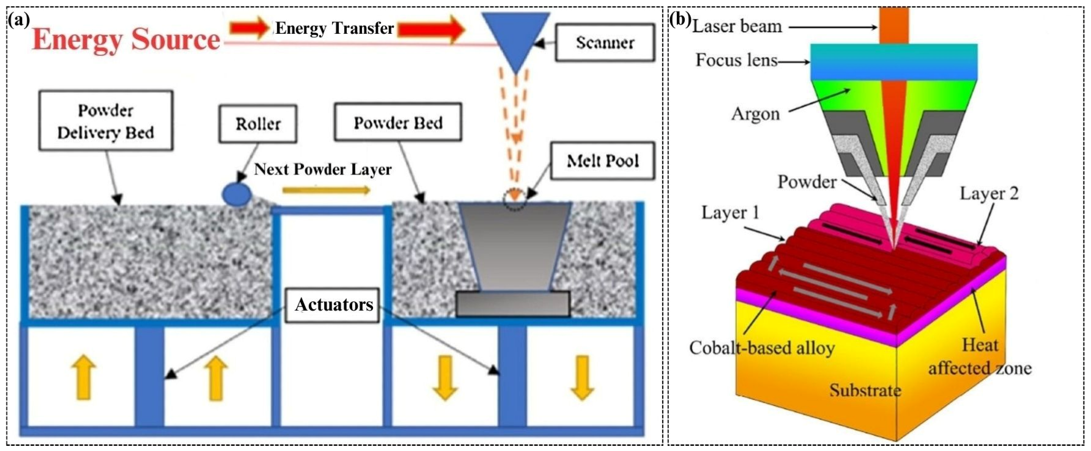
2.1. Thermal-Based AM Technologies
2.1.1. PBF Manufactured Co-Cr-Based Alloys
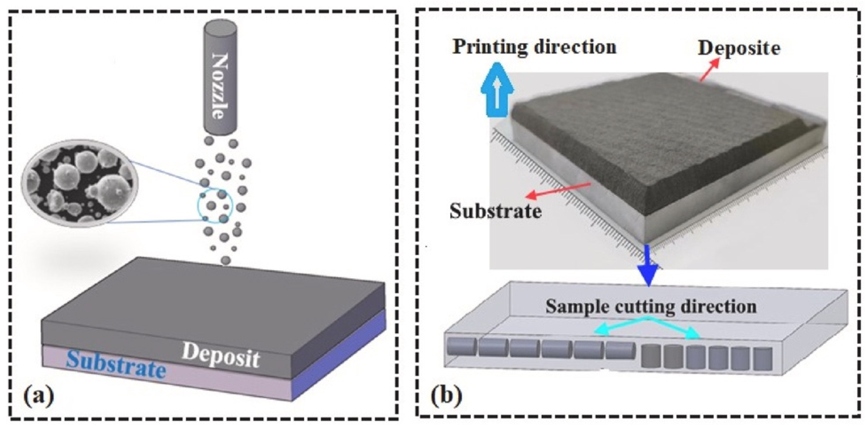
2.1.2. DED Manufactured Co-Cr-Based Alloys
2.1.3. LENS-Manufactured Co-Cr-Based Alloys
2.1.4. EBM-Manufactured Co-Cr-Based Alloys
2.2. Non-Thermal-Based AM Technologies
3. Recent Progress in Additively Manufactured Co-Cr-Based Alloys
4. Impact of Fabricating Parameters on the Printed Co-Cr-Based Alloys
4.1. Influence of Different Process Parameters
4.1.1. Impact of Laser Power
4.1.2. Effect of Input Energy Densities
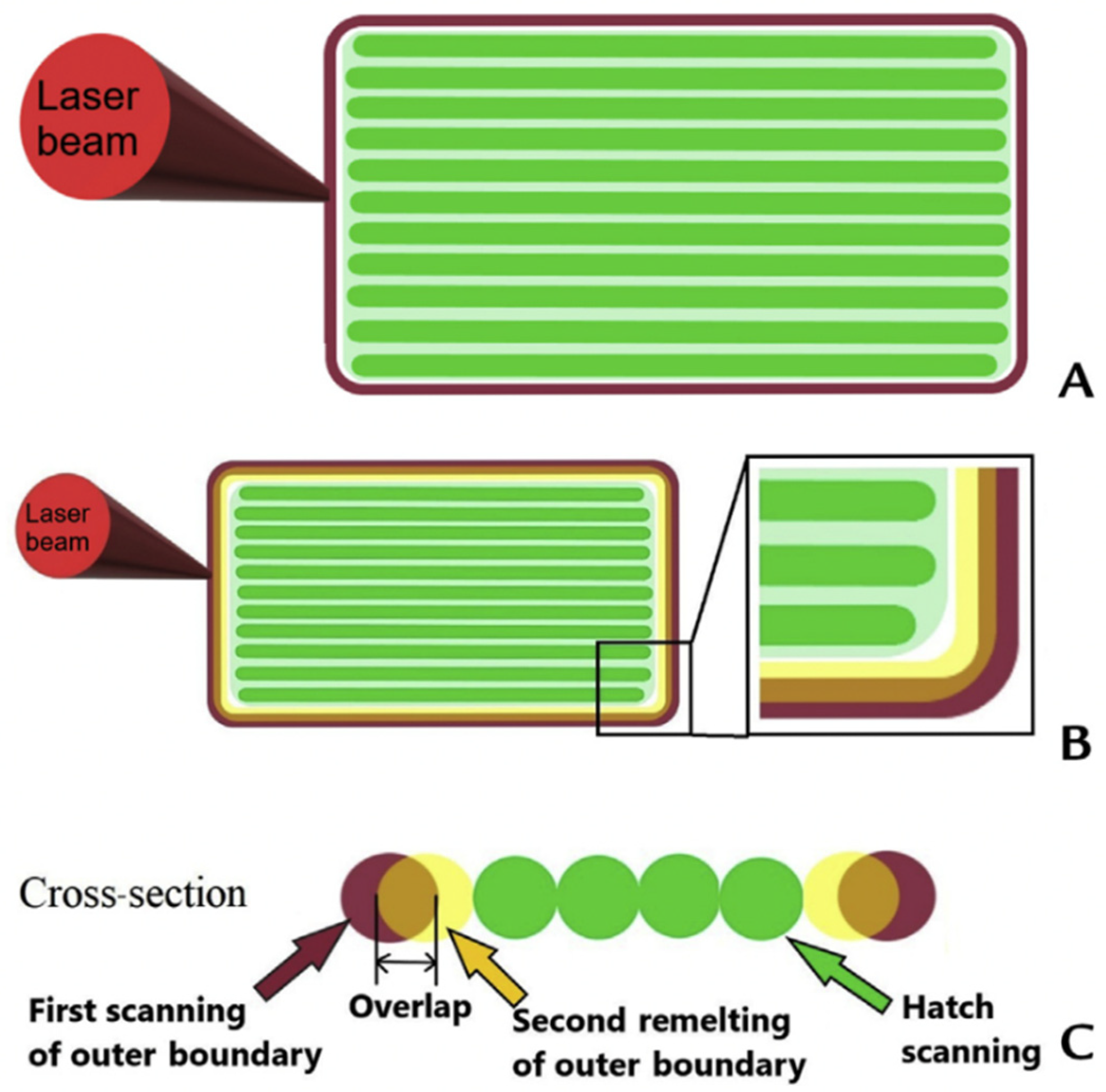
4.1.3. Effect of Laser Scan Strategy
4.1.4. Scanning Speed Effects
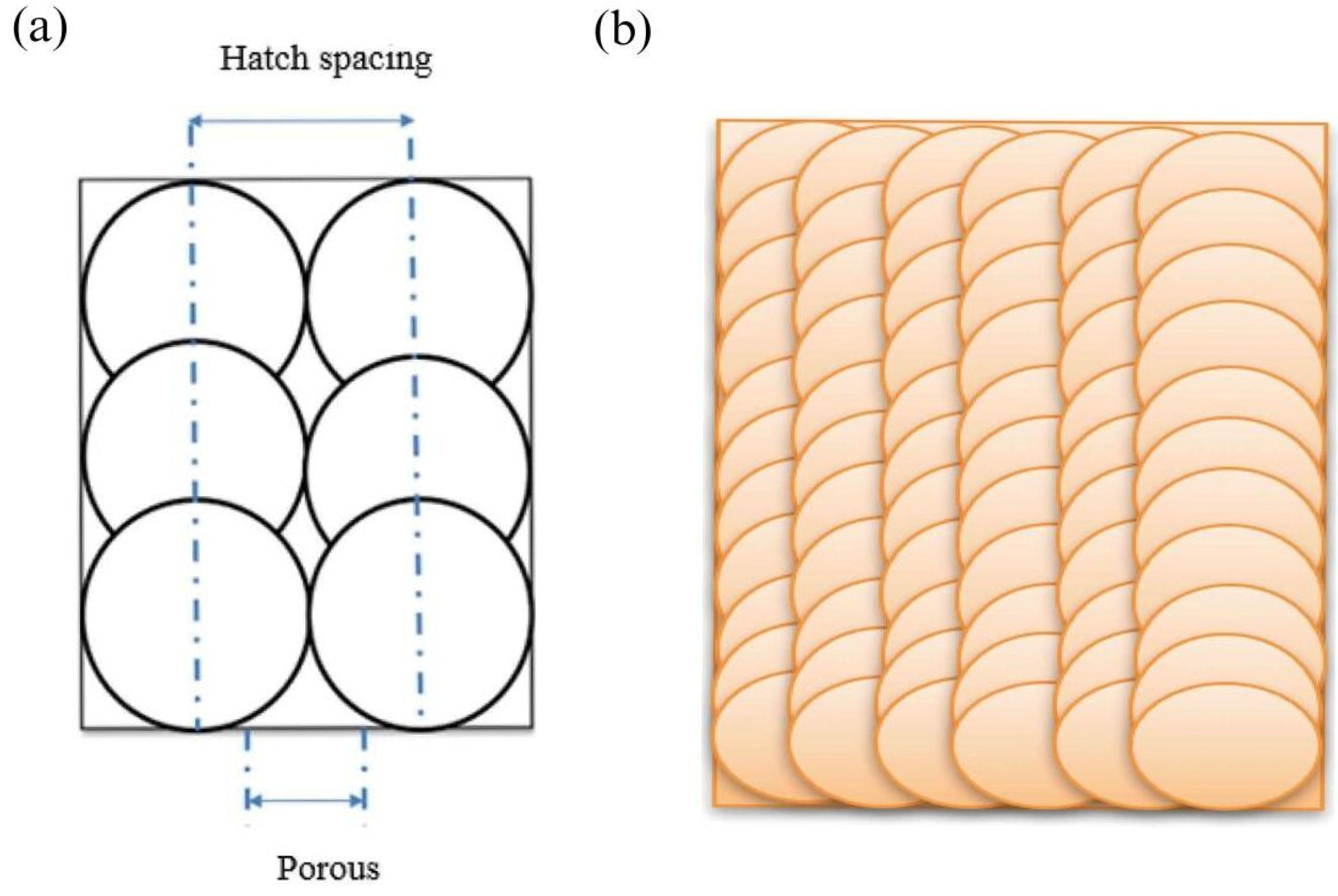
4.1.5. Impact of Interlayer Time and Hatch Spacing
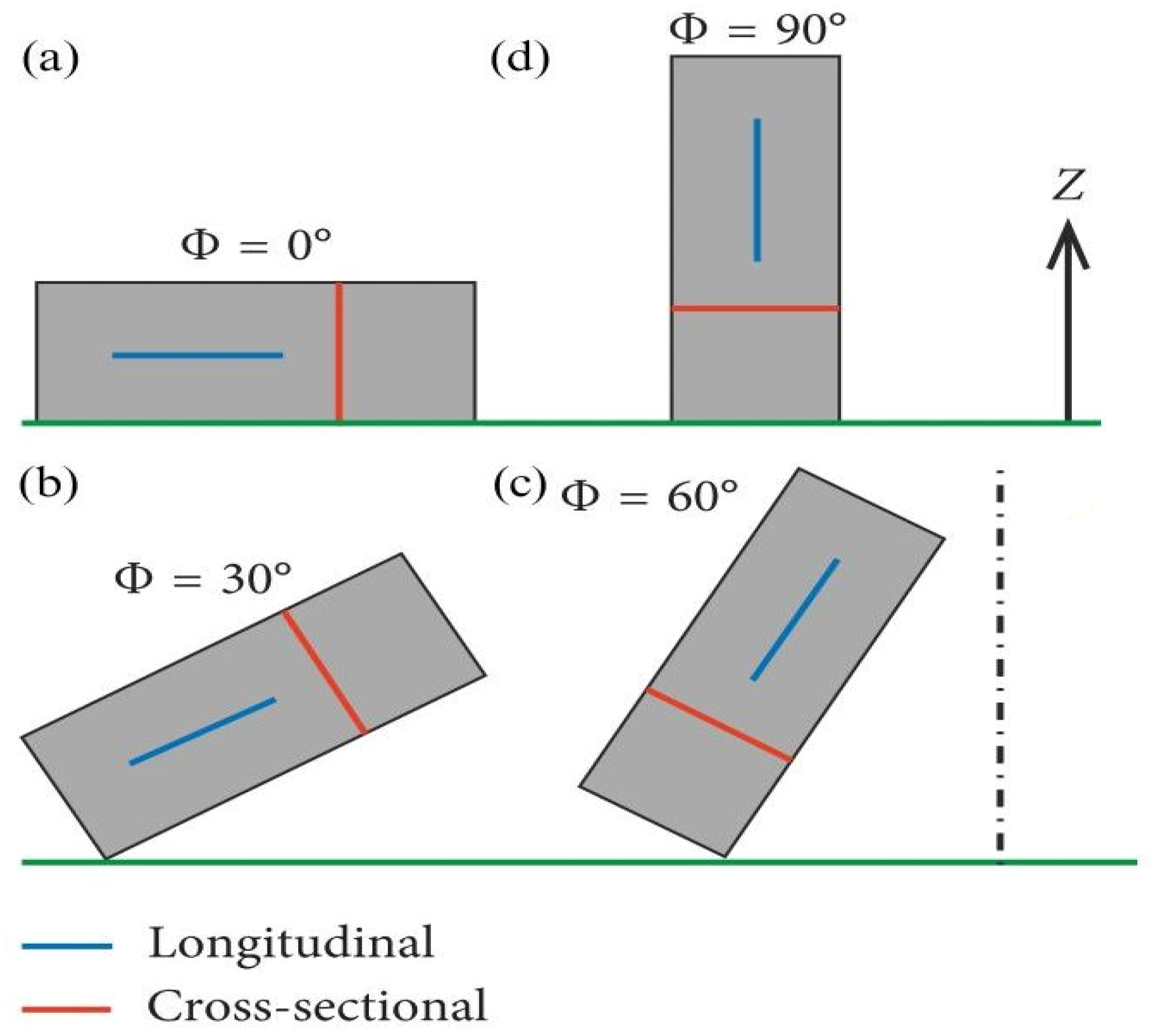
4.1.6. Effect of Build Orientation
4.1.7. Impact of Process Parameters with Melt-Pool Dynamics
4.2. Effect of Post-Processing Treatments
4.2.1. Surface Treatment
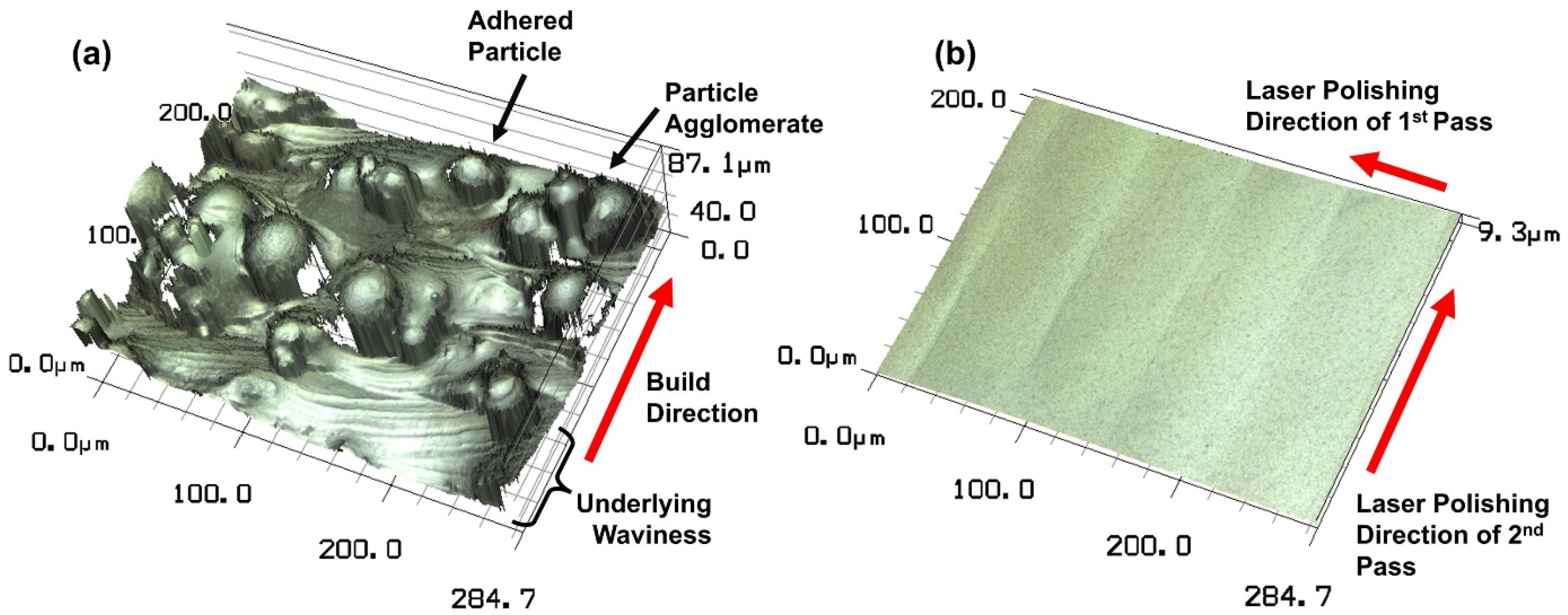
Laser Polishing
Electropolishing
Mechanical Surface Treatments
4.2.2. Heat Treatment
4.3. Critical Facts and Scope for Further Development
5. Key Characteristics of Additively Manufactured Co-Cr-Based Alloys
5.1. Density and Porosity
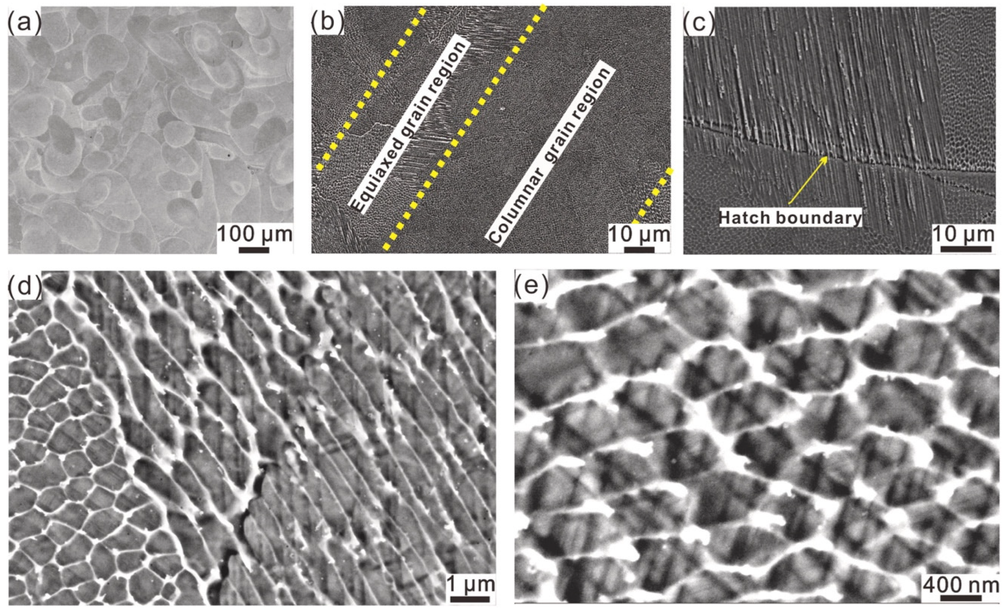
5.2. Microstructural Characteristics
5.3. Surface Finish and Wettability
5.4. Mechanical Characteristics
5.5. Tribological Behavior
5.5.1. Tribological Characteristics of Co-Cr-Mo Alloys
5.5.2. Tribological Characteristics of Co-Cr-W Alloys
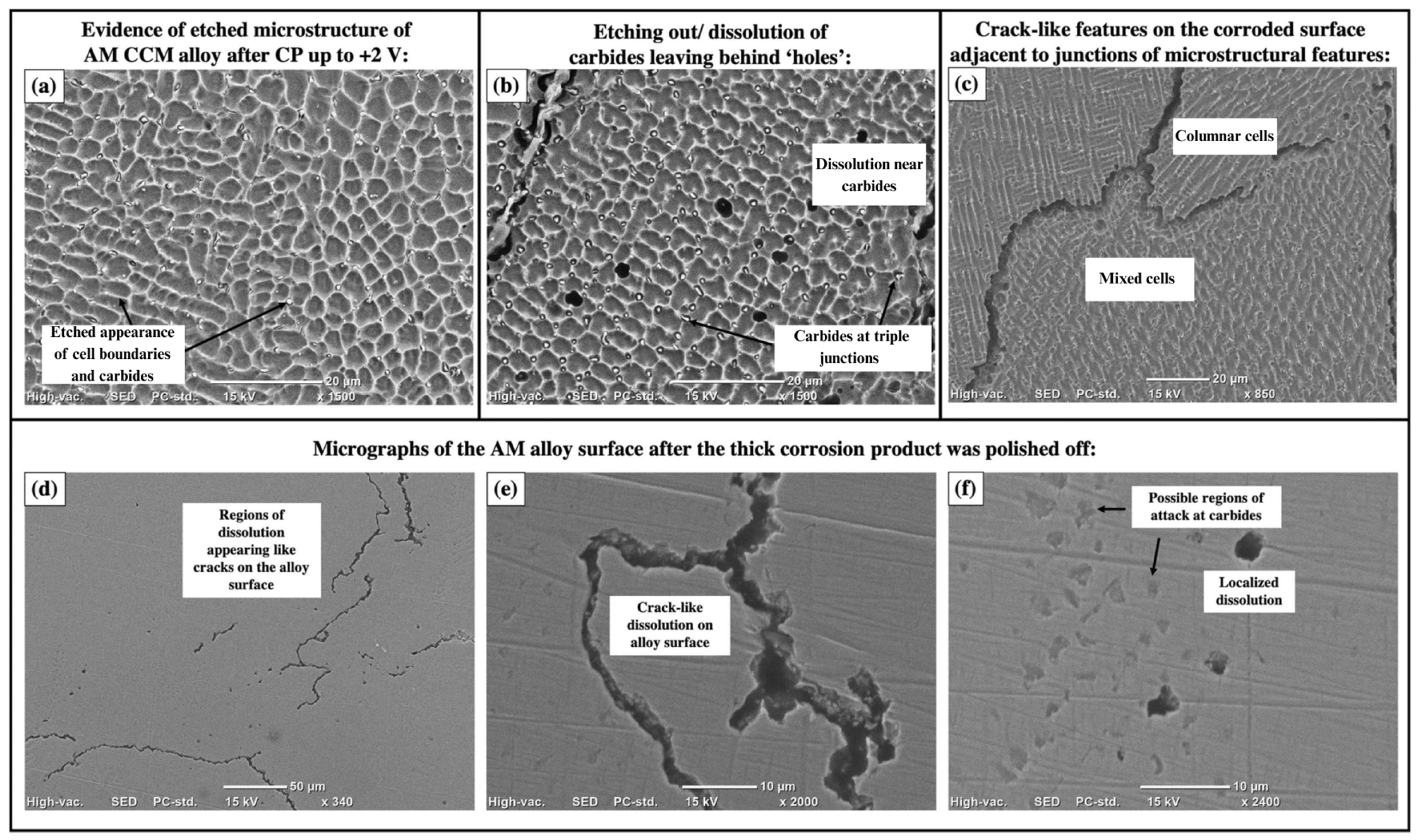
5.6. Corrosion Performance
5.7. Biocompatibility
5.8. Summary and Future Prospects—The Roadmap Ahead
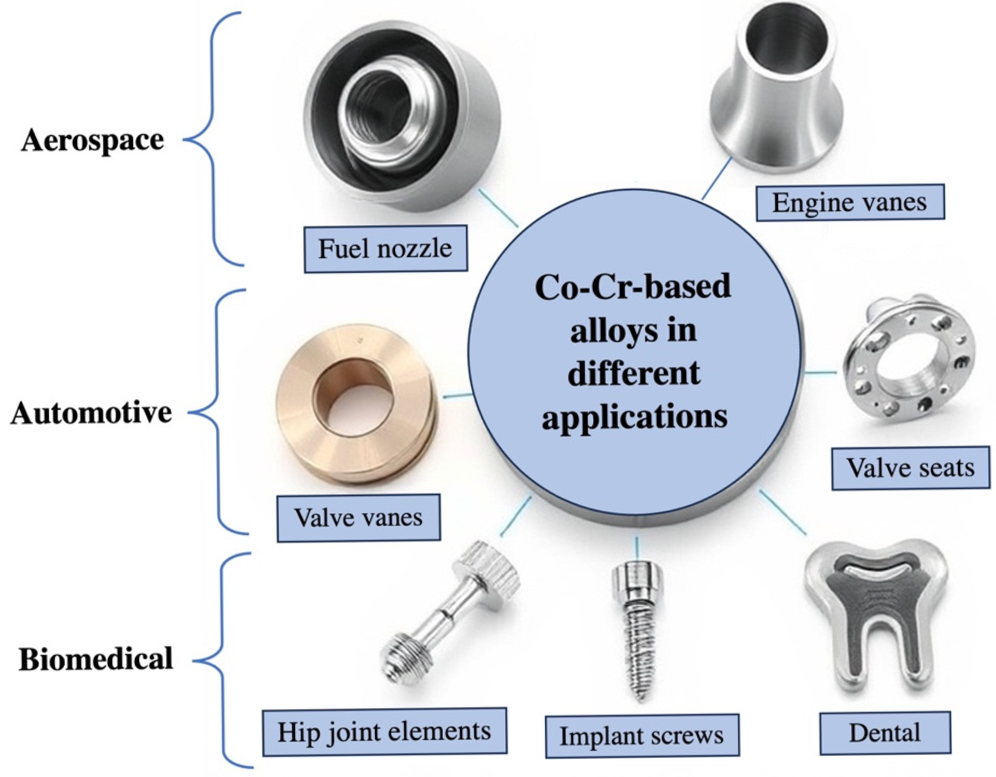
6. Cutting-Edge Applications of 3D-Printed Co-Cr-Based Alloys
6.1. Biomedical Applications
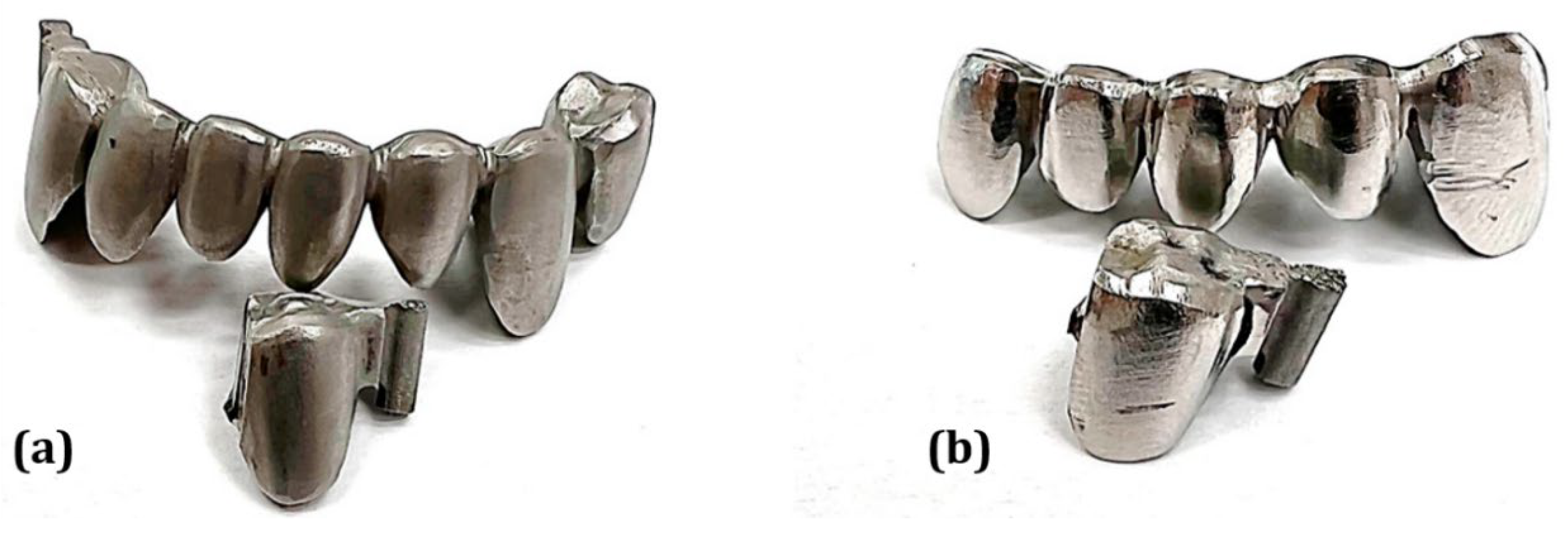
6.1.1. Prosthodontics
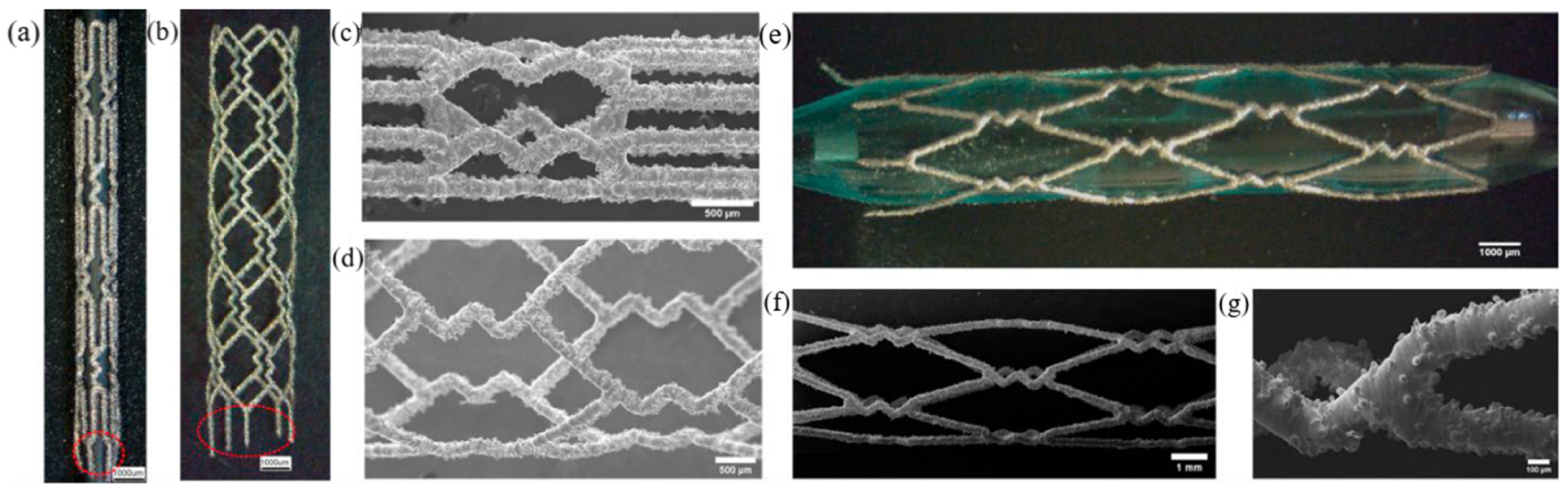
6.1.2. Cardiovascular Stents
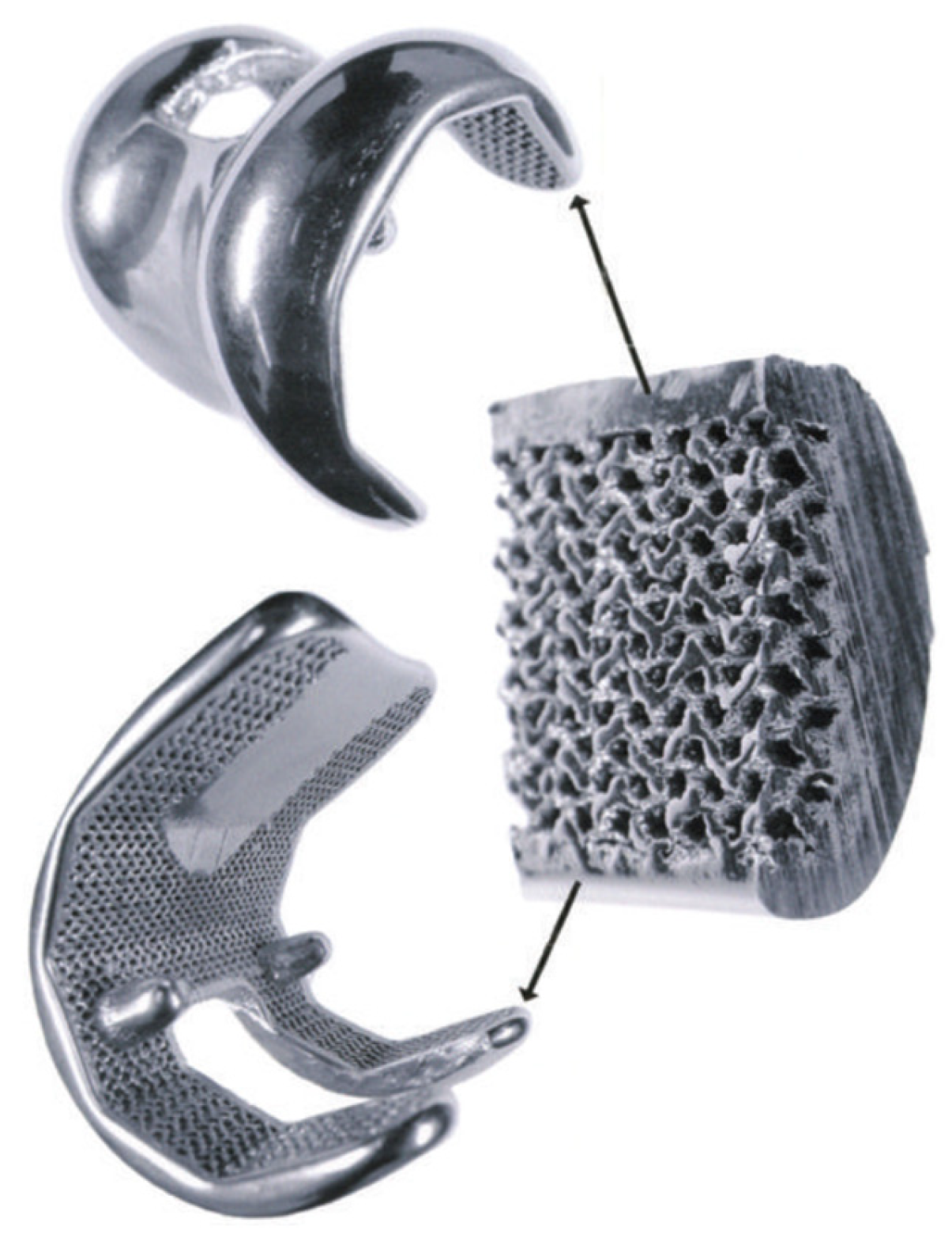
6.1.3. Orthopedic Implants
6.2. Engineering Applications
6.2.1. Aerospace, Oil, Gas, and Power Generation
6.2.2. Remanufacturing and Repair
7. Future Perspectives and Challenges Involved
8. Concluding Remarks
Author Contributions
Funding
Acknowledgments
Conflicts of Interest
Abbreviations
| AB | As-built |
| AFB | Abrasive fluidized bed |
| AM | Additive manufacturing |
| AR | Adaptive remelting |
| BSA | Bovine serum albumin |
| CA | Citric acid |
| CAD | Computer-aided design |
| CAM | Computer-aided manufacturing |
| CCM | Co-Cr-Mo |
| CCW | Co-Cr-W |
| CFD | Computational fluid dynamics |
| COF | Coefficient of friction |
| CP | Cyclic polarization |
| CSAM | Cold spray additive manufacturing |
| DED | Direct energy deposition |
| DMLS | Direct metal laser sintering |
| DTs | Deformation twins |
| Ecorr | Corrosion potential |
| Ebp | Breakdown potential |
| EBM | Electron-beam melting |
| ECP | Electrochemical polishing |
| EIS | Electrochemical impedance spectroscopy |
| EPBF | Electron powder bed fusion |
| FCC | Face-centered cubic |
| GBE | Grain boundary engineering |
| HA | Hydroxyapatite |
| HBSS | Hank’s balanced salt solution |
| HCP | Hexagonal closed-pack |
| HIP | Hot isostatic press |
| HT | Heat treatment/Heat-treated |
| Hv | Hardness in Vickers’ scale |
| icorr | Corrosion current density |
| k | Specific wear rate |
| LAM | Laser-based additive manufacturing |
| LBM | Laser beam melting |
| LED | Linear energy density |
| LENS | Laser-engineered net shaping |
| LMD | Laser metal deposition |
| LPBF | Laser powder bed fusion |
| LSM | Laser surface melting |
| MA | Mechanical alloying |
| MEA | Medium entropy alloy |
| MPBAM | Micro-plasma-based additive manufacturing |
| PBS | Phosphate-buffered solution |
| PDP | Potentiodynamic polarization |
| PEP | Plasma electrolytic polishing |
| Ra | Surface roughness |
| SFs | Stacking faults |
| SHR | Strain hardening rate |
| SLM | Selective laser melting |
| SS | Stainless steel |
| TF | Thermal fatigue |
| TM | Typical melting |
| UC | Unit cell |
| UHMWPE | Ultra-high-molecular weight polyethylene |
| UNSM | Ultrasonic nanocrystal surface modification |
| UTS | Ultimate tensile strength |
| VED | Volumetric energy density |
| WAAM | Wire arc additive manufacturing |
| WLAM | Wire laser additive manufacturing |
| WoS | Web of Science |
References
- Boban, J.; Ahmed, A. Electric discharge aided surface post-treatment of laser powder bed fused non-planar metallic components for enhanced form accuracy. J. Manuf. Process. 2024, 109, 564–582. [Google Scholar] [CrossRef]
- Boban, J.; Ahmed, A.; Jithinraj, E.K.; Rahman, M.A.; Rahman, M. Polishing of additive manufactured metallic components: Retrospect on existing methods and future prospects. Int. J. Adv. Manuf. Technol. 2022, 121, 83–125. [Google Scholar] [CrossRef]
- Malakizadi, A.; Mallipeddi, D.; Dadbakhsh, S.; M’Saoubi, R.; Krajnik, P. Post-processing of additively manufactured metallic alloys—A review. Int. J. Mach. Tools Manuf. 2022, 179, 103908. [Google Scholar] [CrossRef]
- Changdar, A.; Chakraborty, S.S.; Li, Y.; Wen, C. Laser additive manufacturing of aluminum-based stochastic and nonstochastic cellular materials. J. Mater. Sci. Technol. 2024, 183, 89–119. [Google Scholar] [CrossRef]
- Daiy, H.; Najafi, Y.; Ragheb, Z.D.; Abedi, H.R. A review study on thermal stability of powder-based additively manufactured alloys. J. Alloys Compd. 2023, 965, 171384. [Google Scholar] [CrossRef]
- Plessis, A.D.; Razavi, S.M.J.; Benedetti, M.; Murchio, S.; Leary, M.; Watson, M.; Bhate, D.; Berto, F. Properties and applications of additively manufactured metallic cellular materials: A review. Prog. Mater. Sci. 2021, 125, 100918. [Google Scholar] [CrossRef]
- Mussatto, A. Research progress in multi-material laser-powder bed fusion additive manufacturing: A review of the state-of-the-art techniques for depositing multiple powders with spatial selectivity in a single layer. Results Eng. 2022, 16, 100769. [Google Scholar] [CrossRef]
- Boban, J.; Ahmed, A.; Gokcekaya, O.; Nakano, T. Ultra-precision surface treatment of beta-titanium alloy printed using laser and electron beam melting sources. CIRP J. Manuf. Sci. Technol. 2025, 58, 1–19. [Google Scholar] [CrossRef]
- Cornacchia, G.; Cecchel, S.; Battini, D.; Petrogalli, C.; Avanzini, A. Microstructural, mechanical, and tribological characterization of selective laser melted CoCrMo alloy under different heat treatment conditions and hot isostatic pressing. Adv. Eng. Mater. 2022, 24, 2100928. [Google Scholar] [CrossRef]
- Narushima, T.; Ueda, K.; Alfirano, A. Co-Cr Alloys as Effective Metallic Biomaterials. In Advances in Metallic Biomaterials. Springer Series in Biomaterials Science and Engineering, 3rd ed.; Niinomi, M., Narushima, T., Nakai, M., Eds.; Springer: Berlin/Heidelberg, Germany, 2015; pp. 157–178. [Google Scholar]
- AlMangour, B.; Luqman, M.; Grzesiak, D.; Harbi, H.A.; Ijaz, F. Effect of processing parameters on the microstructure and mechanical properties of Co–Cr–Mo alloy fabricated by selective laser melting. Mater. Sci. Eng. A 2020, 792, 139456. [Google Scholar] [CrossRef]
- Romano, S.; Peradotto, E.; Beretta, S.; Ugues, D.; Barricelli, L.; Maculotti, G.; Patriarca, L.; Genta, G. Fatigue strength estimation of net-shape L-PBF Co–Cr–Mo alloy via non-destructive surface measurements. Int. J. Fatigue 2024, 178, 108018. [Google Scholar] [CrossRef]
- Sun, S.H.; Koizumi, Y.; Kurosu, S.; Li, Y.P.; Matsumoto, H.; Chiba, A. Build direction dependence of microstructure and high-temperature tensile property of Co–Cr–Mo alloy fabricated by electron beam melting. Acta Mater. 2014, 64, 154–168. [Google Scholar] [CrossRef]
- Muthuswamy, P.; Dinakaran, D. Microstructure and magnetic properties of cryogenically treated cobalt. Mater. Today Proc. 2021, 46, 4948–4953. [Google Scholar]
- Qian, B.; Saeidi, K.; Kvetková, L.; Lofaj, F.; Xiao, C.; Shen, Z. Defects-tolerant Co-Cr-Mo dental alloys prepared by selective laser melting. Dent. Mater. 2015, 31, 1435–1444. [Google Scholar] [CrossRef]
- Pieniazek, J.A.; Kurtyka, P.; Sulima, I.; Stopka, J. Selected properties and tribological wear alloys Co-Cr-Mo and Co-Cr-Mo-W used in dental prosthetics. Arch. Metall. Mater. 2015, 60, 1569–1574. [Google Scholar] [CrossRef]
- Peter, I.; Rosso, M. Study of Ti-enriched CoCrMo alloy for dental application. IEEE Access 2015, 3, 73–80. [Google Scholar] [CrossRef]
- Nadzieja, J.A.; Szczotok, A. The influence of prosthetic elements manufacturing technology on properties and microstructure shaping Co-Cr-Mo alloys. Eng. Biomater. 2020, 156, 24–31. [Google Scholar]
- Mengiste, B.T.; Arab, A.; Guo, Y.; Lei, Y.; Li, X.; Chen, P.; Xie, J. Effect of strain rate on compressive behavior and deformation mechanism of CoCrNi medium entropy alloy fabricated via cold spray additive manufacturing. J. Alloys Compd. 2024, 980, 173627. [Google Scholar] [CrossRef]
- Hutasoit, N.; Khalik, M.A.; Palanisamy, S. Cold spray additive manufacturing. In Comprehensive Materials Processing, 2nd ed.; Elsevier: Amsterdam, The Netherlands, 2024; Volume 9, pp. 25–56. [Google Scholar]
- Hedberg, Y.S.; Qian, B.; Shen, Z.; Virtanen, S.; Wallinder, I.O. In vitro biocompatibility of CoCrMo dental alloys fabricated by selective laser melting. Dent. Mater. 2014, 30, 525–534. [Google Scholar] [CrossRef]
- Varol, T.; Aksa, H.C.; Yıldız, F.; Akçay, S.B.; Kaya, G.; Beder, M. Influence of post processing on the mechanical properties and wear behavior of selective laser melted Co-Cr-Mo-W alloys. Tribology International. 2024, 192, 109336. [Google Scholar] [CrossRef]
- Konieczny, B.; Wlodarczyk, A.S.; Sokolowski, J.; Bociong, K. Challenges of Co–Cr Alloy Additive Manufacturing Methods in Dentistry—The Current State of Knowledge (Systematic Review). Materials 2020, 13, 3524. [Google Scholar] [CrossRef] [PubMed]
- Bandyopadhyay, A.; Traxel, K.D. Invited review article: Metal-additive manufacturing—Modeling strategies T for application-optimized designs. Addit. Manuf. 2018, 22, 758–774. [Google Scholar] [CrossRef] [PubMed]
- Jung, J.; Choi, M.; Lee, H.; Song, Y.; Na, T.; Kim, J.; Gwon, J.; Han, J.; Lee, B. Effect of line energy on microstructures and mechanical properties of Co-Cr-Mo alloy single-track fabricated by DED method. J. Alloys Compd. 2023, 946, 169381. [Google Scholar] [CrossRef]
- Yang, X.; Li, C.; Ye, Z.; Zhang, X.; Zheng, M.; Gua, J.; Jiang, J. Effects of tribo-film on wear resistance of additive manufactured cobalt-based alloys during the sliding process. Surf. Coat. Technol. 2021, 427, 127784. [Google Scholar] [CrossRef]
- Mazumder, S.; Pantawane, M.V.; Patil, S.M.; Radhakrishnan, M.; Sharma, S.; McKinstry, M.; Dahotre, N.B. Thermokinetically Driven Microstructural Evolution in Laser-Based Directed Energy-Deposited CoCrMo Biomedical Alloy. Adv. Eng. Mater 2022, 24, 2200352. [Google Scholar] [CrossRef]
- Balla, V.K.; Xue, W.; Bose, S.; Bandyopadhyay, A. Engineered Porous Metals for Implants. JOM 2008, 60, 45–49. [Google Scholar]
- Sahasrabudhe, H.; Bose, S.; Bandyopadhyay, A. Laser processed calcium phosphate reinforced CoCrMo for load-bearing applications: Processing and wear induced damage evaluation. Acta Biomater. 2018, 66, 118–128. [Google Scholar] [CrossRef]
- Wei, D.; Koizumi, Y.; Chiba, A.; Ueki, K.; Ueda, K.; Narushima, T.; Tsutsumi, Y.; Hanawa, T. Heterogeneous microstructures and corrosion resistance of biomedical Co-Cr-Mo alloy fabricated by electron beam melting (EBM). Addit. Manuf. 2018, 24, 103–114. [Google Scholar] [CrossRef]
- Mengiste, B.T.; Arab, A.; Guo, Y.; Lei, Y.; Li, X.; Chen, P.; Xie, J. Tuning the mechanical properties of CrCoFeMnNi high entropy alloy via cold spray additive manufacturing associated with heat treatment. Mater. Sci. Eng. A 2024, 894, 146214. [Google Scholar] [CrossRef]
- Vock, S.; Klöden, B.; Kirchner, A.; Weißgärber, T.; Kieback, B. Powders for powder bed fusion: A review. Prog. Addit. Manuf. 2019, 4, 383–397. [Google Scholar] [CrossRef]
- Bricin, D.; Kriz, A. Assessment of usability of WC-Co powder mixtures for SLM. Manuf. Technol. 2018, 18, 719–726. [Google Scholar] [CrossRef]
- Khimich, M.A.; Ibragimov, E.A.; Chebodaeva, V.V.; Prosolov, K.A.; Tolmachev, A.I.; Glukhov, I.A.; Uvarkin, P.V.; Saprykina, N.A.; Saprykin, A.A.; Sharkeev, Y.P. From raw elements to 3D samples: An economical route for Co-Cr-Mo alloy fabrication. J. Alloys Compd. 2024, 978, 173460. [Google Scholar] [CrossRef]
- Ko, K.H.; Kang, H.G.; Huh, Y.H.; Park, C.J.; Cho, L.R. Effects of heat treatment on the microstructure, residual stress, and mechanical properties of Co–Cr alloy fabricated by selective laser melting. J. Mech. Behav. Biomed. Mater. 2022, 126, 105051. [Google Scholar] [CrossRef]
- Yildiz, M.T.; Babacan, N. Comparison of tensile properties and porcelain bond strength in metal frameworks fabricated by selective laser melting using three different Co-Cr alloy powders. J. Prosthet. Dent. 2024, 131, 936–942. [Google Scholar] [CrossRef]
- Mumtaz, K.A.; Erasenthiran, P.; Hopkinson, N. High density selective laser melting of Waspaloy. J. Mater. Process. Technol. 2008, 195, 77–87. [Google Scholar] [CrossRef]
- Li, J.; Chen, C.; Liao, J.; Liu, L.; Ye, X.; Lin, S.; Ye, J. Bond strengths of porcelain to cobalt-chromium alloys made by casting, milling, and selective laser melting. J. Prosthet. Dent. 2017, 118, 69–75. [Google Scholar] [CrossRef]
- Helou, H.A.; Kassis, J.; Zaidani, W.; Bylasani, T. The effect of repeated baking of porcelain on its bonding strength to a Co-Cr alloy 3D-printed by selective laser melting. Saudi Dent. J. 2024, 36, 296–300. [Google Scholar] [CrossRef]
- Huang, Z.; Zhang, L.; Zhu, J.; Zhang, X. Clinical marginal and internal fit of metal ceramic crowns fabricated with a selective laser melting technology. J. Prosthet. Dent. 2015, 113, 623–627. [Google Scholar] [CrossRef]
- Koutsoukis, T.; Zinelis, S.; Eliades, G.; Al-Wazzan, K.; Rifaiy, M.A.; Al-Jabbari, Y.S. Selective laser melting technique of Co-Cr dental alloys: A review of structure and properties and comparative analysis with other available techniques. J. Prosthodont. 2015, 24, 303–312. [Google Scholar] [CrossRef]
- Kim, E.H.; Lee, D.H.; Kwon, S.M.; Kwon, T.Y. A microcomputed tomography evaluation of the marginal fit of cobalt-chromium alloy copings fabricated by new manufacturing techniques and alloy systems. J. Prosthet. Dent. 2017, 117, 393–399. [Google Scholar] [CrossRef]
- Munyensanga, P.; Bricha, M.; Mabrouk, K.E. Functional characterization of biomechanical loading and biocorrosion resistance properties of novel additively manufactured porous CoCrMo implant: Comparative analysis with gyroid and rhombic dodecahedron. Mater. Chem. Phys. 2024, 316, 129139. [Google Scholar] [CrossRef]
- Prashanth, K.G.; Eckert, J. Formation of metastable cellular microstructures in selective laser melted alloys. J. Alloys Compd. 2017, 707, 27–34. [Google Scholar] [CrossRef]
- Liu, L.; Ding, Q.; Zhong, Y.; Zou, J.; Wu, J.; Chiu, Y.L.; Li, J.; Zhang, Z.; Yu, Q.; Shen, Z. Dislocation network in additive manufactured steel breaks strength–ductility trade-off. Mater. Today 2018, 21, 354–361. [Google Scholar] [CrossRef]
- Porter, D.A.; Easterling, K.E.; Sherif, M.Y. Phase Transformations in Metals and Alloys, 3rd ed.; CRC Press: Boca Raton, FL, USA, 2009. [Google Scholar]
- Koizumi, Y.; Suzuki, S.; Yamanaka, K.; Lee, B.S.; Sato, K.; Li, Y.; Kurosu, S.; Matsumoto, H.; Chiba, A. Strain-induced martensitic transformation near twin boundaries in a biomedical Co-Cr-Mo alloy with negative stacking fault energy. Acta Mater. 2013, 61, 1648–1661. [Google Scholar] [CrossRef]
- Wang, Z.; Tang, S.Y.; Scudino, S.; Ivanov, Y.P.; Qu, R.T.; Wang, D.; Yang, C.; Zhang, W.W.; Greer, A.L.; Eckert, J.; et al. Additive manufacturing of a martensitic Co–Cr–Mo alloy: Towards circumventing the strength–ductility trade-off. Addit. Manuf. 2021, 37, 101725. [Google Scholar] [CrossRef]
- Kaffash, N.H.; Marandi, S.; Beidokhti, B.; Farshidianfar, M.H. Effect of heat treatment on microstructure and wear properties of laser additively manufactured 316 L stainless steel/Co-Cr-W alloy part using directed energy deposition method. Mater. Today Commun. 2024, 38, 107865. [Google Scholar] [CrossRef]
- Dai, D.; Gu, D. Thermal behavior and densification mechanism during selective laser melting of copper matrix composites: Simulation and experiments. Mater. Des. 2014, 55, 482–491. [Google Scholar] [CrossRef]
- Shi, H.; Cho, J.R.; An, D.G. Microstructure and hardness of Stellite 21 deposited on hot forging die using direct metal deposition technology. J. Mech. Sci. Technol. 2020, 34, 1283–1288. [Google Scholar] [CrossRef]
- Jendrzejewski, R.; Śliwiński, G.; Krawczuk, M.; Ostachowicz, W. Temperature and stress fields induced during laser cladding. Comput. Struct. 2004, 82, 653–658. [Google Scholar] [CrossRef]
- Smoqi, Z.; Toddy, J.; Halliday, H.; Shielda, J.E.; Rao, P. Process-structure relationship in the directed energy deposition of cobalt-chromium alloy (Stellite 21) coatings. Mater. Des. 2021, 197, 109229. [Google Scholar] [CrossRef]
- Zhao, R.; Chen, C.; Wang, W.; Cao, T.; Shuai, S.; Xu, S.; Hu, T.; Liao, H.; Wang, J.; Ren, Z. On the role of volumetric energy density in the microstructure and mechanical properties of laser powder bed fusion Ti-6Al-4V alloy. Addit. Manuf. 2022, 51, 102605. [Google Scholar] [CrossRef]
- Liu, W.; Xie, Q.; Cao, Y.; Wang, J.; Bai, P. Optimization of processing parameters for LPBF-manufactured CoCr alloys based on laser volume energy density. J. Mater. Res. Technol. 2023, 27, 4053–4063. [Google Scholar] [CrossRef]
- Mahmood, M.A.; Rehman, A.U.; Ristoscu, C.; Demir, M.; Pelin, G.P.; Pitir, F.; Salamci, M.U.; Mihailescu, I.N. Advances in Laser Additive Manufacturing of Cobalt–Chromium Alloy Multi-Layer Mesoscopic Analytical Modelling with Experimental Correlations: From Micro-Dendrite Grains to Bulk Objects. Nanomaterials 2022, 12, 802. [Google Scholar] [CrossRef]
- Zhou, X.; Li, K.; Zhang, D.; Liu, X.; Ma, J.; Liu, W.; Shen, Z. Textures formed in a CoCrMo alloy by selective laser melting. J. Alloys Compd. 2015, 631, 153–164. [Google Scholar] [CrossRef]
- Geiger, F.; Kunze, K.; Etter, T. Tailoring the texture of IN738LC processed by selective laser melting (SLM) by specific scanning strategies. Mater. Sci. Eng. A 2016, 661, 240–246. [Google Scholar] [CrossRef]
- Lövgren, N.; Roxner, R.; Klemendz, S.; Larsson, C. Effect of production method on surface roughness, marginal and internal fit, and retention of cobalt-chromium single crowns. J. Prosthet. Dent. 2017, 118, 95–101. [Google Scholar] [CrossRef]
- Cosma, C.; Moldovan, M.; Simion, M.; Balc, N. Impact of laser parameters on additively manufactured cobalt-chromium restorations. J. Prosthet. Dent. 2022, 128, 421–429. [Google Scholar] [CrossRef]
- Zou, S.; Zhao, Z.; Xu, W.; Ni, X.; Zhang, L.; Wu, W.; Kong, D.; He, X.; Wang, L.; Dong, C. Effects of scanning speeds on the wear behavior of CoCrW alloy fabricated by selective laser melting. Opt. Laser Technol. 2022, 147, 107652. [Google Scholar] [CrossRef]
- Younsi, T.; Boher, C.; Soveja, A. Influence of interlayer time on the microstructural state of CoCrMo coatings applied by selective laser melting on an iron-based substrate for different numbers of layers. Mater. Today Commun. 2022, 32, 103776. [Google Scholar] [CrossRef]
- Kumar, S. Selective Laser Sintering/Melting. Compr. Mater. Process. 2014, 10, 93–134. [Google Scholar]
- Uva, N.C.; Suya, P.A.P. Selective laser melting and post-processing stages for enhancing the material behavior of cobalt-chromium alloy in total hip replacement: A review. Mater. Manuf. Process. 2023, 38, 495–515. [Google Scholar]
- Hitzler, L.; Hirsch, J.; Heine, B.; Merkel, M.; Hall, W.; Ochsner, A. On the anisotropic mechanical properties of selective laser melted stainless steel. Materials 2017, 10, 1136. [Google Scholar] [CrossRef]
- Hitzler, L.; Segbaya, F.A.; Williams, P.; Heine, B.; Heitzmann, M.; Hall, W.; Merkel, M.; Ochsner, A. Additive Manufacturing of Cobalt-Based Dental Alloys: Analysis of Microstructure and Physicomechanical Properties. Adv. Mater. Sci. Eng. 2018, 12, 8213023. [Google Scholar] [CrossRef]
- Yin, J.; Liu, W.; Cao, Y.; Zhang, L.; Wang, J.; Li, Z.; Zhao, Z.; Bai, P. Rapid prediction of the relationship between processing parameters and molten pool during selective laser melting of cobalt-chromium alloy powder: Simulation and experiment. J. Alloys Compd. 2021, 892, 162200. [Google Scholar] [CrossRef]
- Boban, J.; Abhilash, P.M.; Ahmed, A.; Rahman, M.A. An overview on post-processing of metal additive manufactured components. In Comprehensive Materials Processing, 2nd ed.; Hashmi, S., Ed.; Elsevier: Oxford, UK, 2024; pp. 231–270. [Google Scholar]
- Gora, W.S.; Tian, Y.; Cabo, A.P.; Ardron, M.; Maier, R.R.; Prangnell, P.; Weston, N.J.; Hand, D.P. Enhancing surface finish of additively manufactured titanium and cobalt chrome elements using laser based finishing. Phys. Procedia 2016, 83, 258–263. [Google Scholar] [CrossRef]
- Richter, B.; Radel, T.; Pfefferkorn, F.E. Sensitivity of surface roughness to laser parameters used for polishing additively manufactured Co-Cr alloy. Surf. Coat. Technol. 2022, 451, 128872. [Google Scholar] [CrossRef]
- Yung, K.; Xiao, T.; Choy, H.; Wang, W.; Cai, Z. Laser polishing of additive manufactured CoCr alloy components with complex surface geometry. J. Mater. Process. Technol. 2018, 262, 53–64. [Google Scholar] [CrossRef]
- Wang, W.J.; Yung, K.C.; Choy, H.S.; Xiao, T.Y.; Cai, Z.X. Effects of laser polishing on surface microstructure and corrosion resistance of additive manufactured CoCr alloys. Appl. Surf. Sci. 2018, 443, 167–175. [Google Scholar] [CrossRef]
- Yung, K.C.; Wang, W.J.; Xiao, T.Y.; Choy, H.S.; Mo, X.Y.; Zhang, S.S.; Cai, Z.X. Laser polishing of additive manufactured CoCr components for controlling their wettability characteristics. Surf. Coat. Technol. 2018, 351, 89–98. [Google Scholar] [CrossRef]
- Demir, A.G.; Previtali, B. Additive manufacturing of cardiovascular CoCr stents by selective laser melting. Mater. Des. 2017, 119, 338–350. [Google Scholar] [CrossRef]
- He, R.; Cao, X.; Langi, E.; Masseling, L.; Vogt, F.; Zhao, L. Electrochemical polishing, characterisation and in vitro evaluation of additively manufactured CoCr stents with personalised designs. Biomater. Adv. 2024, 159, 213835. [Google Scholar] [CrossRef] [PubMed]
- Finazzi, V.; Demir, A.G.; Biffi, C.A.; Chiastra, C.; Migliavacca, F.; Petrini, L.; Previtali, B. Design Rules for Producing Cardiovascular Stents by Selective Laser Melting: Geometrical Constraints and Opportunities. Procedia Struct. Integr. 2019, 15, 16–23. [Google Scholar] [CrossRef]
- Takeyama, J.; Sakurai, T.; Shimpo, H.; Kawamura, N.; Ohkubo, C. In vitro assessment of polishing efficiency for additive-manufactured Co–Cr alloy clasps. J. Prosthodont. Res. 2024, 68, 591–598. [Google Scholar] [CrossRef] [PubMed]
- Atzeni, E.; Genna, S.; Salmi, A.; Trovalusci, F.; Rubino, G. Abrasive fluidized bed finishing of additive manufactured cobalt-chrome parts: Effects on surface morphology and fatigue behavior. Int. J. Adv. Manuf. Technol. 2023, 124, 1939–1949. [Google Scholar] [CrossRef]
- Takaichi, A.; Kajima, Y.; Kittikundecha, N.; Htat, H.L.; Cho, H.H.W.; Hanawa, T.; Yoneyama, T.; Wakabayashi, N. Effect of heat treatment on the anisotropic microstructural and mechanical properties of Co–Cr–Mo alloys produced by selective laser melting. J. Mech. Behav. Biomed. Mater. 2020, 102, 103496. [Google Scholar] [CrossRef]
- Sing, S.L.; Huang, S.; Yeong, W.Y. Effect of solution heat treatment on microstructure and mechanical properties of laser powder bed fusion produced cobalt-28chromium-6molybdenum. Mater. Sci. Eng. A 2020, 769, 138511. [Google Scholar] [CrossRef]
- Zhang, M.; Yang, Y.; Song, C.; Bai, Y.; Xiao, Z. An investigation into the aging behavior of CoCrMo alloys fabricated by selective laser melting. J. Alloys Compd. 2018, 750, 878–886. [Google Scholar] [CrossRef]
- Khademitab, M.; Vecchis, P.R.D.; Staszel, P.; Vaicik, M.K.; Chmielus, M.; Amir Mostafaei, A. Structure-property relationships of differently heat-treated binder jet printed Co-Cr-Mo biomaterial. Mater. Today Commun. 2024, 38, 107716. [Google Scholar] [CrossRef]
- Sola, A.; Nouri, A. Microstructural porosity in additive manufacturing: The formation and detection of pores in metal parts fabricated by powder bed fusion. J. Adv. Manuf. Process. 2019, 1, e10021. [Google Scholar] [CrossRef]
- Jhavar, S.; Jain, N.K.; Paul, C.P. Development of micro-plasma transferred arc (m-PTA) wire deposition process for additive layer manufacturing applications. J. Mater. Process. Technol. 2014, 214, 1102–1110. [Google Scholar] [CrossRef]
- Kumar, P.; Sawant, M.S.; Jain, N.K.; Gupta, S. Microstructure characterization of Co-Cr-Mo-xTi alloys developed by micro-plasma based additive manufacturing for knee implants. J. Mater. Res. Technol. 2022, 21, 252–266. [Google Scholar] [CrossRef]
- Kumar, P.; Sawant, M.S.; Jain, N.K.; Gupta, S. Study of mechanical characteristics of additively manufactured Co-Cr-Mo-2/4/6Ti alloys for knee implant material. CIRP J. Manuf. Sci. Technol. 2022, 39, 261–275. [Google Scholar] [CrossRef]
- Kurosu, S.; Matsumoto, H.; Chiba, A. Isothermal phase transformation in biomedical Co-29Cr-6Mo alloy without addition of carbon or nitrogen. Metall. Mater. Trans. A 2010, 41, 2613–2625. [Google Scholar] [CrossRef]
- Kajima, Y.; Takaichi, A.; Kittikundecha, N.; Nakamoto, T.; Kimura, T.; Nomura, N.; Kawasaki, A.; Hanawa, T.; Takahashi, H.; Wakabayashi, N. Effect of heat-treatment temperature on microstructures and mechanical properties of Co–Cr–Mo alloys fabricated by selective laser melting. Mater. Sci. Eng. A 2018, 726, 21–31. [Google Scholar] [CrossRef]
- Dong, X.; Li, N.; Yu, J.; Qu, Y.; Wu, M.; Zhou, Y.; Shi, H.; Peng, H.; Zhang, Y.; Yan, J. Effect of grain boundary character on isothermal phase transformation and mechanical properties of Co-Cr-Mo alloy fabricated by selective laser melting. J. Alloys Compd. 2022, 903, 163904. [Google Scholar] [CrossRef]
- Li, H.; Wang, M.; Lou, D.; Xia, W.; Fang, X. Microstructural features of biomedical cobalt–chromium–molybdenum (CoCrMo) alloy from powder bed fusion to aging heat treatment. J. Mater. Sci. Technol. 2020, 45, 146–156. [Google Scholar] [CrossRef]
- Zhou, Y.; Wei, W.; Yan, J.; Liu, W.; Li, N.; Li, H.; Xu, S. Microstructures and metal-ceramic bond properties of Co-Cr biomedical alloys fabricated by selective laser melting and casting. Mater. Sci. Eng. A 2019, 759, 594–602. [Google Scholar] [CrossRef]
- Priya, P.; Mercer, B.; Huang, S.; Aboukhatwa, M.; Yuan, L.; Chaudhuri, S. Towards prediction of microstructure during laser based additive manufacturing process of Co-Cr-Mo powder beds. Mater. Des. 2020, 196, 109117. [Google Scholar] [CrossRef]
- León, M.R.; Husain, N.A.; Methani, M.M.; Özcan, M. Chemical composition, surface roughness, and ceramic bond strength of additively manufactured cobalt-chromium dental alloys. J. Prosthet. Dent. 2021, 125, 825–831. [Google Scholar] [CrossRef]
- Adams, J.J.; Duoss, E.B.; Malkowski, T.F.; Motala, M.J.; Ahn, B.Y.; Nuzzo, R.G.; Bernhard, J.T.; Lewis, J.A. Conformal printing of electrically small antennas on three-dimensional surfaces. Adv. Mater. 2011, 23, 1335–1340. [Google Scholar] [CrossRef]
- Alvarez, K.; Nakajima, H. Metallic scaffolds for bone regeneration. Materials 2009, 2, 790–832. [Google Scholar] [CrossRef]
- Hooreweder, B.V.; Lietaert, K.; Neirinck, B.; Lippiatt, N.; Wevers, M. CoCr F75 scaffolds produced by additive manufacturing: Influence of chemical etching on powder removal and mechanical performance. J. Mech. Behav. Biomed. Mater. 2017, 68, 216–223. [Google Scholar] [CrossRef]
- Sanz, C.; Navas, V.G. Structural integrity ofdirect metal laser sintered parts subjected to thermal and finishing treatments. J. Mater. Process. Technol. 2013, 213, 2126–2136. [Google Scholar] [CrossRef]
- Gaytan, S.M.; Murr, L.E.; Martinez, E.; Martinez, J.L.; Machado, B.I.; Ramirez, D.A.; Medina, F.; Collins, S.; Wicher, R.B. Comparison of microstructures and mechanical properties of solid and mesh cobalt-base alloy prototypes fabricated by electron beam melting. Metall. Mater. Trans. A 2010, 41, 3216–3227. [Google Scholar] [CrossRef]
- Meacock, C.G.; Vilar, R. Structure and properties of a biomedical Co–Cr–Mo alloy produced by laser powder microdeposition. J. Laser Appl. 2009, 21, 88–95. [Google Scholar] [CrossRef]
- Barucca, G.; Santecchia, E.; Majni, G.; Girardin, E.; Bassoli, E.; Denti, L.; Gatto, A.; Iuliano, L.; Moskalewicz, T.; Mengucci, P. Structural characterization of biomedical Co–Cr–Mo components produced by direct metal laser sintering. Mater. Sci. Eng. C 2015, 48, 263–269. [Google Scholar] [CrossRef]
- Saraiva, B.R.C.; Novotny, L.; Carpentieri, B.; Keller, T.F.; Faberova, M.; Bures, R.; Rodrigues, S.F.; Neto, J.R.D.B.; Antunes, L.H.M.; Masoumi, M.; et al. Effect of cyclic loading on microstructure and crack propagation in additively manufactured biomaterial Co-Cr-Mo alloy. J. Mater. Res. Technol. 2023, 26, 3905–3916. [Google Scholar] [CrossRef]
- Wang, B.; An, X.; Huang, Z.; Song, M.; Ni, S.; Liu, S. Nitrogen doped Co-Cr-Mo-W based alloys fabricated by selective laser melting with enhanced strength and good ductility. J. Alloys Compd. 2019, 785, 305–311. [Google Scholar] [CrossRef]
- Tunthawiroon, P.; Li, Y.; Koizumi, Y.; Chiba, A. Strain-controlled iso-thermal fatigue behavior of Co–29Cr–6Mo used for tooling materials in Al die casting. Mater. Sci. Eng. 2017, 703, 27–36. [Google Scholar] [CrossRef]
- Wu, Y.; Liu, Y.; Chen, H.; Chen, Y.; Li, H.; Cao, X. Developing the ductility and thermal fatigue cracking property of laser-deposited Stellite 6 coatings by adding titanium and nickel. Mater. Des. 2019, 162, 271–284. [Google Scholar] [CrossRef]
- Yang, X.; Li, C.; Zhang, M.; Ye, Z.; Zhang, X.; Zheng, M.; Gu, J.; Zhu, H.; Wang, F. Study on tensile and thermal fatigue behaviors of additively manufactured cobalt-based alloys alloying with Al and Ni. Mater. Sci. Eng. A 2022, 840, 142914. [Google Scholar] [CrossRef]
- Kolken, H.M.A.; Callens, S.J.P.; Leeflang, M.A.; Mirzaali, M.J.; Zadpoor, A.A. Merging strut-based and minimal surface meta-biomaterials: Decoupling surface area from mechanical properties. Addit. Manuf. 2022, 52, 102684. [Google Scholar] [CrossRef]
- Kolken, H.M.A.; Garcia, A.F.; Du Plessis, A.; Meynen, A.; Rans, C.; Scheys, L.; Mirzaali, M.J.; Zadpoor, A.A. Mechanisms of fatigue crack initiation and propagation in auxetic meta-biomaterials. Acta Biomater. 2022, 138, 398–409. [Google Scholar] [CrossRef]
- Wanniarachchi, C.T.; Arjunan, A.; Baroutaji, A.; Singh, M. Mechanical performance of additively manufactured cobalt-chromium-molybdenum auxetic meta-biomaterial bone scaffolds. J. Mech. Behav. Biomed. Mater. 2022, 134, 105409. [Google Scholar] [CrossRef]
- Caravaggi, P.; Liverani, E.; Leardini, A.; Fortunato, A.; Belvedere, C.; Baruffaldi, F.; Fini, M.; Parrilli, A.; Belmonte, M.M.; Tomesani, L.; et al. CoCr porous scaffolds manufactured via selective laser melting in orthopedics: Topographical, mechanical, and biological characterization. J. Biomed. Mater. Res. Part B 2019, 107, 2343–2353. [Google Scholar] [CrossRef]
- Carluccio, D.; Xu, C.; Venezuela, J.; Cao, Y.; Kent, D.; Bermingham, M.; Demir, A.G.; Previtali, B.; Ye, Q.; Dargusch, M. Additively manufactured iron-manganese for biodegradable porous load-bearing bone scaffold applications. Acta Biomater. 2020, 103, 346–360. [Google Scholar] [CrossRef]
- Liverani, E.; Fortunato, A. Stiffness prediction and deformation analysis of Cobalt-Chromium lattice structures: From periodic to functionally graded structures produced by additive manufacturing. J. Manuf. Process. 2021, 68, 104–114. [Google Scholar] [CrossRef]
- Chen, Q.; Thouas, G.A. Metallic implant biomaterials. Mater. Sci. Eng. R Rep. 2015, 87, 1–57. [Google Scholar] [CrossRef]
- Saha, S.; Kiran, K.U.V.; Zhang, X.; Hou, X.; Roy, S. Investigating the tribological and corrosion behavior of Co–Cr alloy as an implant material for orthodontic applications. Wear 2023, 523, 204755. [Google Scholar] [CrossRef]
- Amanov, A. Advancement of tribological properties of Ti–6Al–4V alloy fabricated by selective laser melting. Tribol. Int. 2021, 155, 106806. [Google Scholar] [CrossRef]
- Amanov, A.; Pyun, Y.S. Local heat treatment with and without ultrasonic nanocrystal surface modification of Ti-6Al-4V alloy: Mechanical and tribological properties. Surf. Coat. Technol. 2017, 326, 343–354. [Google Scholar] [CrossRef]
- Amanov, A. Effect of post-additive manufacturing surface modification temperature on the tribological and tribocorrosion properties of Co-Cr-Mo alloy for biomedical applications. Surf. Coat. Technol. 2021, 421, 127378. [Google Scholar] [CrossRef]
- Mantripragada, V.P.; Czernik, B.L.; Ebraheim, N.A.; Jayasuriya, A.C. An over-view of recent advances in designing orthopedic and craniofacial implants. J. Biomed. Mater. Res. Part A 2012, 101, 3349–3364. [Google Scholar] [CrossRef]
- Lerebours, A.; Demangel, C.; Dembinski, L.; Bouvier, S.; Rassineux, A.; Egles, C. Effect of the Residual Porosity of CoCrMo Bearing Parts Produced by Additive Manufacturing on Wear of Polyethylene. Biotribology 2020, 23, 100138. [Google Scholar] [CrossRef]
- Sahasrabudhe, H.; Traxel, K.D.; Bandyopadhyay, A. Understanding wear behavior of 3D-Printed calcium phosphate-reinforced CoCrMo in biologically relevant media. J. Mech. Behav. Biomed. Mater. 2021, 120, 104564. [Google Scholar] [CrossRef]
- Mazumder, S.; Metselaar, H.S.C.; Sukiman, N.L.; Zulkifli, N.W.M. Friction and wear behavior of fluoride added Si3N4-SiC ceramic composites at elevated temperature. Ceram. Int. 2023, 49, 12787–12795. [Google Scholar] [CrossRef]
- Fischer, A.; Dudzinski, W.; Gleising, B.; Stemmer, P. Analyzing Mild- and Ultra-Mild Sliding Wear of Metallic Materials by Transmission Electron Microscopy. In Advanced Analytical Methods in Tribology. Microtechnology and MEMS; Dienwiebel, M., De Barros Bouchet, M.I., Eds.; Springer: Cham, Germany, 2018. [Google Scholar]
- Mazumder, S.; Metselaar, H.S.C.; Sukiman, N.L.; Zulkifli, N.W.M. Tribomechanical Behaviour of Non-oxide Ceramic Matrix Composites in Dry Sliding. In Tribological Applications of Composite Materials; Springer Nature: Berlin/Heidelberg, Germany, 2021. [Google Scholar]
- Mazumder, S.; Kumar, O.P.; Kotnees, D.K.; Mandal, N. Tribological influences of CuO into 3Y-TZP ceramic composite in conformal contact. ASME J. Tribol. 2019, 141, 031606. [Google Scholar] [CrossRef]
- Mazumder, S.; Barad, B.B.; Show, B.K.; Mandal, N. Tribological property enhancement of 3Y-TZP ceramic by the combined effect of CaF2 and MgO phases. Ceram. Int. 2019, 45, 13447–13455. [Google Scholar] [CrossRef]
- Mazumder, S.; Metselaar, H.S.C.; Sukiman, N.L.; Zulkifli, N.W.M. An overview of fluoride-based solid lubricants in sliding contacts. J. Eur. Ceram. Soc. 2020, 40, 4974–4996. [Google Scholar] [CrossRef]
- Atapour, M.; Standish, T.E.; Henderson, J.D.; Wei, Z.; Dehnavi, V.; Hedberg, Y.S. Influence of Proteins and Building Direction on the Corrosion and Tribocorrosion of CoCrMo Fabricated by Laser Powder Bed Fusion. ACS Biomater. Sci. Eng. 2024, 10, 2880–2893. [Google Scholar] [CrossRef]
- Kashani, H.; Amadeh, A.; Ghasemi, H.M. Room and high temperature wear behaviors of nickel and cobalt base weld overlay coatings on hot forging dies. Wear 2007, 262, 800–806. [Google Scholar] [CrossRef]
- Yang, X.; Li, C.; Zhang, M.; Ye, Z.; Zhang, X.; Zheng, M.; Gu, J.; Li, J.; Li, S. Dry sliding wear behavior of additively manufactured CoCrWNixAly alloys. Wear 2022, 496–497, 204285. [Google Scholar] [CrossRef]
- Huang, Y.C.; Wu, H.; Xu, T.Z.; Wang, R.; Zhang, S.; Zhang, C.H.; Wu, C.L.; Chen, H.T. Microstructure, tribological property and high temperature tensile property of Co-Cr-Ni-W alloy parts fabricated by laser directed energy deposition. Surf. Coat. Technol. 2024, 483, 130807. [Google Scholar] [CrossRef]
- Dreano, A.; Fouvry, S.; Guillonneau, G. A tribo-oxidation abrasive wear model to quantify the wear rate of a cobalt-based alloy subjected to fretting in low-to-medium temperature conditions. Tribol. Int. 2018, 125, 128–140. [Google Scholar] [CrossRef]
- Zhou, K.; Chen, J.; Wang, T.; Su, Y.; Qiao, L.; Yan, Y. Effect of surface energy on protein adsorption behaviours of treated CoCrMo alloy surfaces. Appl. Surf. Sci. 2020, 520, 146354. [Google Scholar] [CrossRef]
- Atapour, M.; Wang, X.; Persson, M.; Wallinder, I.O.; Hedberg, Y.S. Corrosion of binder jetting additively manufactured 316L stainless steel of different surface finish. J. Electrochem. Soc. 2020, 167, 131503. [Google Scholar] [CrossRef]
- Tonelli, L.; Fortunato, A.; Ceschini, L. CoCr alloy processed by Selective Laser Melting (SLM): Effect of laser energy density on microstructure, surface morphology, and hardness. J. Manuf. Process. 2020, 52, 106–119. [Google Scholar] [CrossRef]
- Atapour, M.; Sanaei, S.; Wei, Z.; Sheikholeslam, M.; Henderson, J.D.; Eduok, U.; Hosein, Y.K.; Holdsworth, D.W.; Hedberg, Y.S.; Ghorbani, H.R. In vitro corrosion and biocompatibility behavior of CoCrMo alloy manufactured by laser powder bed fusion parallel and perpendicular to the build direction. Electrochim. Acta 2023, 445, 142059. [Google Scholar] [CrossRef]
- Narayanan, D.; Liu, M.; Kuttolamadom, M.; Castaneda, H. Identification and development of a new local corrosion mechanism in a Laser Engineered Net Shaped (LENS) biomedical Co-Cr-Mo alloy in Hank’s solution. Corros. Sci. 2022, 207, 110599. [Google Scholar] [CrossRef]
- Girão, D.D.C.; Béreš, M.; Jardini, A.L.; Filho, R.M.; Silva, C.C.; Siervo, A.D.; Abreu, H.F.G.; Araújo, W.S. An assessment of biomedical CoCrMo alloy fabricated by direct metal laser sintering technique for implant applications. Mater. Sci. Eng. C 2020, 107, 110305. [Google Scholar] [CrossRef]
- Vidal, C.V.; Muñoz, A.I. Electrochemical aspects in biomedical alloy Characterization: Electrochemical impedance spectroscopy. In Biomedical Engineering, Trends in Materials Science; IntechOpen: Hong Kong, China, 2011; pp. 283–306. [Google Scholar]
- Seo, B.; Park, H.K.; Park, K.B.; Kang, H.S.; Park, K. Effect of hydrogen peroxide on Cr oxide formation of additive manufactured CoCr alloys during plasma electrolytic polishing. Mater. Lett. 2021, 294, 129736. [Google Scholar] [CrossRef]
- Lu, Y.; Guo, S.; Yang, Y.; Liu, Y.; Zhou, Y.; Wu, S.; Zhao, C.; Lin, J. Effect of thermal treatment and fluoride ions on the electrochemical corrosion behavior of selective laser melted CoCrW alloy. J. Alloys Compd. 2018, 730, 552–562. [Google Scholar] [CrossRef]
- Logan, N.; Sherif, A.; Cross, A.J.; Collins, S.N.; Traynor, A.; Bozec, L.; Parkin, I.P.; Brett, P. TiO2-coated CoCrMo: Improving the osteogenic differentiation and adhesion of mesenchymal stem cells in vitro. J. Biomed. Mater. Res. A 2015, 103, 1208–1217. [Google Scholar] [CrossRef]
- Poh, C.K.; Shi, Z.; Tan, X.W.; Liang, Z.C.; Foo, X.M.; Tan, H.C.; Neoh, K.G.; Wang, W. Cobalt chromium alloy with immobilized bmp peptide for enhanced bone growth. J. Orthop. Res. 2011, 29, 1424–1430. [Google Scholar] [CrossRef]
- Jakobsen, S.S.; Baas, J.; Jakobsen, T.; Soballe, K. Acid etching does not improve CoCrMo implant osseointegration in a canine implant model 2010. Hip Int. 2021, 20, 171–178. [Google Scholar] [CrossRef]
- Mazumder, S.; Man, K.; Radhakrishnan, M.; Pantawane, M.V.; Palaniappan, S.; Patil, S.M.; Yang, Y.; Dahotre, N.B. Microstructure enhanced biocompatibility in laser additively manufactured CoCrMo biomedical alloy. Biomater. Adv. 2023, 150, 213415. [Google Scholar] [CrossRef]
- Bandyopadhyay, A.; Shivaram, A.; Isik, M.; Avila, J.D.; Dernell, W.S.; Bose, S. Additively manufactured calcium phosphate reinforced CoCrMo alloy: Bio-tribological and biocompatibility evaluation for load-bearing implants. Addit. Manuf. 2019, 28, 312–324. [Google Scholar] [CrossRef]
- Liu, W.; Qing, H.; Pei, X.; Wang, J. Internal adaptation of cobalt-chromium posts fabricated by selective laser melting technology. J. Prosthet. Dent. 2019, 121, 455–460. [Google Scholar] [CrossRef]
- Kassapidou, M.; Stenport, V.F.; Johansson, C.B.; Syverud, M.; Johansson, H.; Börjesson, J.; Hjalmarsson, L. Cobalt chromium alloys in fixed prosthodontics: Investigations of mechanical properties and microstructure. J. Prosthet. Dent. 2023, 130, 255.e1–255.e10. [Google Scholar] [CrossRef]
- Xin, X.Z.; Xiang, N.; Chen, J.; Wei, B. In vitro biocompatibility of Co–Cr alloy fabricated by selective laser melting or traditional casting techniques. Mater. Lett. 2012, 88, 101–103. [Google Scholar] [CrossRef]
- Moraru, E.; Stoica, A.M.; Donțu, O.; Cănănău, S.; Stoica, N.A.; Constantin, V.; Cioboată, D.D.; Bădiță-Voicu, L.L. Mechanical and Surface Characteristics of Selective Laser Melting-Manufactured Dental Prostheses in Different Processing Stages. Materials 2023, 16, 6141. [Google Scholar] [CrossRef]
- Bangalore, S.; Toklu, B.; Patel, N.; Feit, F.; Stone, G.W. Newer-Generation Ultrathin Strut Drug-Eluting Stents Versus Older Second-Generation Thicker Strut Drug-Eluting Stents for Coronary Artery Disease. Circulation 2018, 138, 2216–2226. [Google Scholar] [CrossRef]
- Kennedy, S.M.; Vasanthanathan, A.; Amudhan, K. Exploring the frontiers of metal additive manufacturing in orthopaedic implant development. MethodsX 2024, 13, 103056. [Google Scholar] [CrossRef] [PubMed]
- Brogini, S.; Sartori, M.; Giavaresi, G.; Cremascoli, P.; Alemani, F.; Bellini, D.; Martini, L.; Maglio, M.; Pagani, S.; Fini, M. Osseointegration of additive manufacturing Ti–6Al–4V and Co–Cr–Mo alloys, with and without surface functionalization with hydroxyapatite and type I collagen. J. Mech. Behav. Biomed. Mater. 2021, 115, 104262. [Google Scholar] [CrossRef]
- Xiang, D.D.; Wang, P.; Tan, X.P.; Chandra, S.; Wang, C.; Nai, M.L.S.; Tor, S.B.; Liu, W.Q.; Liu, E. Anisotropic microstructure and mechanical properties of additively manufactured Co–Cr–Mo alloy using selective electron beam melting for orthopedic implants. Mater. Sci. Eng. A 2019, 765, 138270. [Google Scholar] [CrossRef]
- Kennametal Develops First Stellite Powder for 3D Printing. In Powder Metallurgy Review; Metal Powder Technology: Shrewsbury, UK, 2021; Volume 10. Available online: https://www.pm-review.com/kennametal-launches-stellite-powder-for-additive-manufacturing/ (accessed on 10 December 2024).
- Stellite 6 Additive Manufacturing Customer Case Study. 2023. Available online: https://www.stellite.com/us/en/resources/stellite-blog/stellite-6-additive-manufacturing-case-study.html (accessed on 11 December 2024).
- Metal AM in the Aerospace Sector: From Early Successes to the Transformation of an Industry. In Metal Additive Manufacturing; Technology, Information and Media: Shrewsbury, UK, 2023; Volume 9. Available online: https://www.metal-am.com/articles/metal-am-in-the-aerospace-sector-from-early-successes-to-the-transformation-of-an-industry/ (accessed on 11 December 2024).
- Diaz, E.; Amado, J.M.; Montero, J.; Tobar, M.J.; Yáñez, A. Comparative Study of Co-based Alloys in Repairing Low Cr-Mo steel Components by Laser Cladding. Phys. Procedia 2012, 39, 368–375. [Google Scholar] [CrossRef]
- Piasecki, A.; Bartkowski, D.; Młynarczyk, A.; Dudziak, A.; Gościański, M.; Kasprowiak, M. Laser cladding of Stellite 6 on low carbon steel for repairing components in automotive applications using disk laser. Arch. Mech. Technol. Autom. 2013, 33, 25–34. [Google Scholar]
- Diaz, E.; Tobar, M.J.; Yáñez, A.; García, J.; Taibo, J. Laser Powder Welding with a Co-based alloy for repairing steam circuit components in thermal power stations. Phys. Procedia 2010, 5, 349–358. [Google Scholar] [CrossRef]
- Foster, J.; Cullen, C.; Fitzpatrick, S.; Payne, G.; Hall, L.; Marashi, J. Remanufacture of hot forging tools and dies using laser metal deposition with powder and a hard-facing alloy Stellite 21®. J. Remanuf. 2019, 9, 189–203. [Google Scholar] [CrossRef]


| Sl. No. | Specimen | Composition | |||||
|---|---|---|---|---|---|---|---|
| Co | Cr | Mo | W | Si | Mn | ||
| 1. | Co-Cr-Mo | 62.06 | 29.95 | 5.85 | __ | 0.82 | 1.32 |
| 2. | Co-Cr-Mo-W | 60.31 | 26.25 | 6.29 | 6.38 | 0.89 | __ |
| 3. | Co-Cr-W | 56.83 | 31.06 | __ | 9.95 | 1.4 | 0.76 |
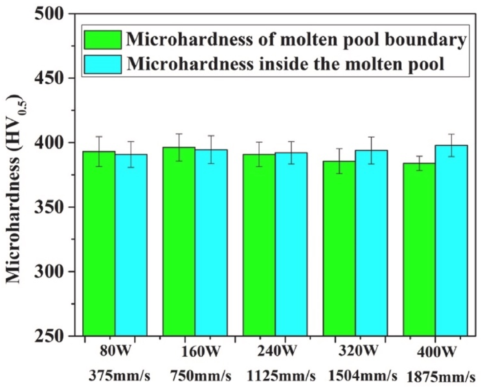
| Specimen | Laser Power, P (W) | Scanning Speed, v (mm/s) | Layer Thickness, t (mm) | Hatch Spacing, h (mm) | Volumetric Energy Density, VED (J/mm3) |
|---|---|---|---|---|---|
| 1. | 80 | 375 | 0.03 | 0.08 | 88 |
| 2. | 160 | 750 | |||
| 3. | 240 | 1125 | |||
| 4. | 320 | 1504 | |||
| 5. | 400 | 1875 |
| Different Alloys and Their Build Orientations | Young’s Modulus, E (GPa) | Yield Strength, RP0.2 (MPa) | Elongation at Failure, At (%) | Ultimate Tensile Strength, Rm (MPa) |
|---|---|---|---|---|
| Co-Cr-Mo 0°_AB Co-Cr-Mo 0°_HT | 98.38 ± 17.01 156.48 ± 19.50 | 702 ± 15.4 819 ± 29.1 | 5.7 ± 1.04 13.3 ± 2.32 | 923 ± 32.4 1097 ± 21.6 |
| Co-Cr-Mo 30°_AB Co-Cr-Mo 30°_HT | 105.32 ± 19.39 149.73 ± 6.29 | 783 ± 23.7 1002 ± 41.1 | 6.7 ± 1.94 8.3 ± 0.81 | 1102 ± 45.2 1262 ± 14.1 |
| Co-Cr-Mo 60°_AB Co-Cr-Mo 60°_HT | 112.11 ± 58.51 105.67 ± 13.18 | 696 ± 34.3 808 ± 37.8 | 7.5 ± 2.10 9.4 ± 1.32 | 1012 ± 24.0 1054 ± 20.9 |
| Co-Cr-Mo 90°_AB Co-Cr-Mo 90°_HT | 100.21 ± 6.95 164.54 ± 15.10 | 674 ± 9.0 757 ± 7.2 | 14.8 ± 1.62 16.7 ± 1.51 | 1033 ± 12.4 1052 ± 6.3 |
| Co-Cr-W 0°_AB Co-Cr-W 0°_HT | 183.44 ± 15.58 216.32 ± 21.99 | 917 ± 9.9 655 ± 26.6 | 11.1 ± 1.14 15.0 ± 1.54 | 1263 ± 8.6 1111 ± 8.9 |
| Co-Cr-W 30°_AB Co-Cr-W 30°_HT | 147.50 ± 20.57 186.96 ± 7.90 | 965 ± 5.9 651 ± 4.9 | 10.4 ± 1.31 15.5 ± 1.04 | 1272 ± 10.3 1127 ± 12.3 |
| Co-Cr-W 60°_AB Co-Cr-W 60°_HT | 167.17 ± 26.23 214.51 ± 29.25 | 845 ±11.1 669 ± 20.0 | 17.1 ± 1.35 18.0 ± 2.90 | 1247 ± 6.1 1162 ± 13.4 |
| Co-Cr-W 90°_AB Co-Cr-W 90°_HT | 138.55 ± 6.93 202.35 ± 22.08 | 755 ± 8.7 658 ± 7.1 | 24.3 ± 0.70 16.9 ± 1.51 | 1188 ± 6.3 1108 ± 10.9 |
| Parameter | Solution Tested | |||
|---|---|---|---|---|
| NaCl | NaCl + Albumin | PBS | PBS + Albumin | |
| Ecorr (mVAg/AgCl) | −164 ± 12 | −674 ± 14 | −201 ± 5 | −700 ± 6 |
| Icorr (μA/cm2) | 0.56 ± 0.17 | 2.28 ± 0.92 | 0.33 ± 0.08 | 4.11 ± 0.83 |
| Ebp (mVAg/AgCl) | 414 ± 4 | 546 ± 6 | 539 ± 4 | 558 ± 5 |
Disclaimer/Publisher’s Note: The statements, opinions and data contained in all publications are solely those of the individual author(s) and contributor(s) and not of MDPI and/or the editor(s). MDPI and/or the editor(s) disclaim responsibility for any injury to people or property resulting from any ideas, methods, instructions or products referred to in the content. |
© 2025 by the authors. Licensee MDPI, Basel, Switzerland. This article is an open access article distributed under the terms and conditions of the Creative Commons Attribution (CC BY) license (https://creativecommons.org/licenses/by/4.0/).
Share and Cite
Mazumder, S.; Boban, J.; Ahmed, A. A Comprehensive Review of Recent Advancements in 3D-Printed Co-Cr-Based Alloys and Their Applications. J. Manuf. Mater. Process. 2025, 9, 169. https://doi.org/10.3390/jmmp9050169
Mazumder S, Boban J, Ahmed A. A Comprehensive Review of Recent Advancements in 3D-Printed Co-Cr-Based Alloys and Their Applications. Journal of Manufacturing and Materials Processing. 2025; 9(5):169. https://doi.org/10.3390/jmmp9050169
Chicago/Turabian StyleMazumder, Subhrojyoti, Jibin Boban, and Afzaal Ahmed. 2025. "A Comprehensive Review of Recent Advancements in 3D-Printed Co-Cr-Based Alloys and Their Applications" Journal of Manufacturing and Materials Processing 9, no. 5: 169. https://doi.org/10.3390/jmmp9050169
APA StyleMazumder, S., Boban, J., & Ahmed, A. (2025). A Comprehensive Review of Recent Advancements in 3D-Printed Co-Cr-Based Alloys and Their Applications. Journal of Manufacturing and Materials Processing, 9(5), 169. https://doi.org/10.3390/jmmp9050169