
Corrosion Performance of Chemically Passivated and Ion Beam-Treated Austenitic–Martensitic Steel in the Marine Environment

 ,
,
Abstract
1. Introduction
2. Materials and Methods
3. Results
3.1. Electrochemical Study
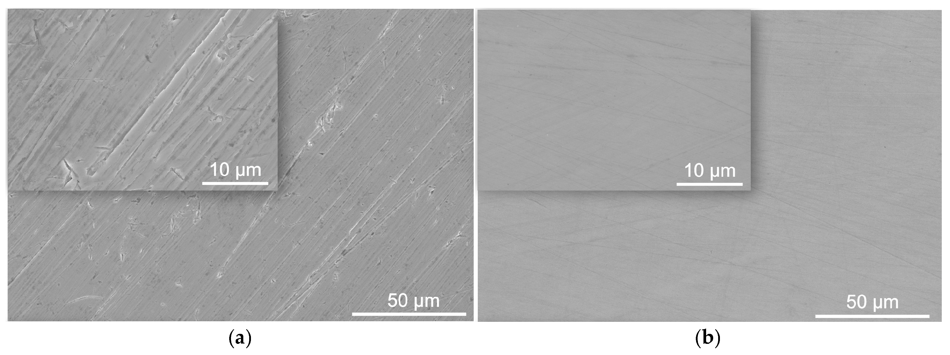
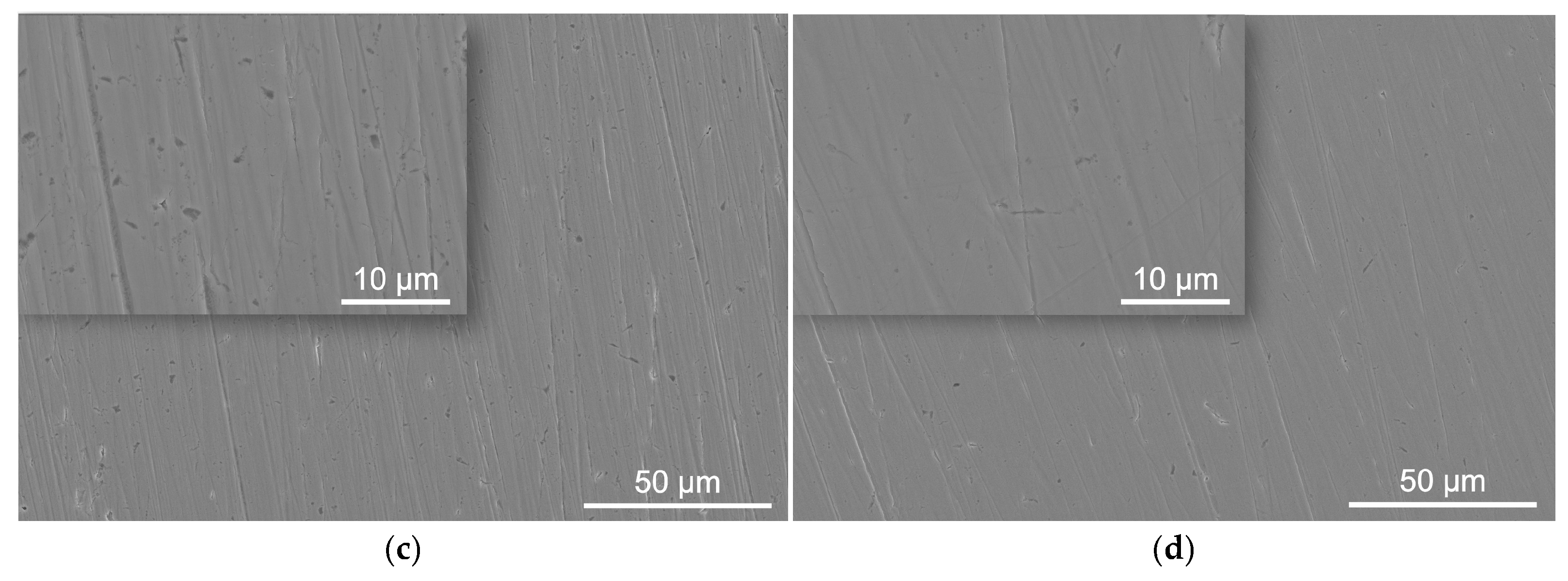
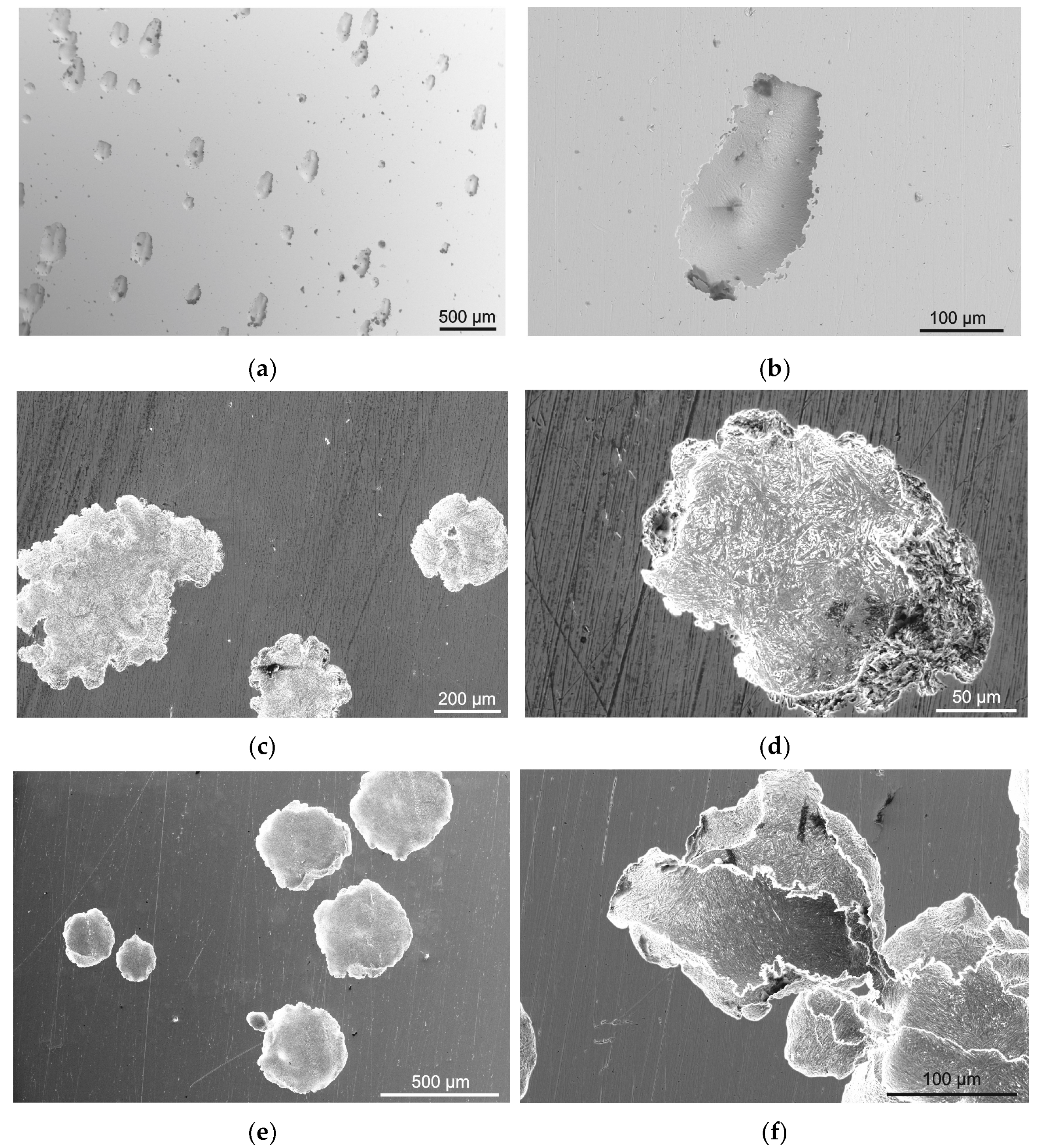
3.2. Surface Morphology
- (1)
- O2 + 4e− + 2H2O → 4OH− (cathodic reaction);
- (2)
- Fe0 → 2e− + Fe2+; Ni0 → 2e− + Ni2+; (primary anodic processes);
- (3)
- Ni2+ + 2Cl− →NiCl2; Fe2+ + 2OH− → Fe(OH)2;
- (4)
- Fe0 − 2e− + 2H2O → Fe(OH)2 + 2H+; Ni0 − 2e− + 2H2O→Ni(OH)2 + 2H+ (anodic reactions);
- (5)
- The formation of corrosion products (Fe(OH)2, Fe(OH)3, FeOOH, Fe2O3, FeCl2, NiCl2, NiO) upon interaction with hydroxide and chlorine ions.
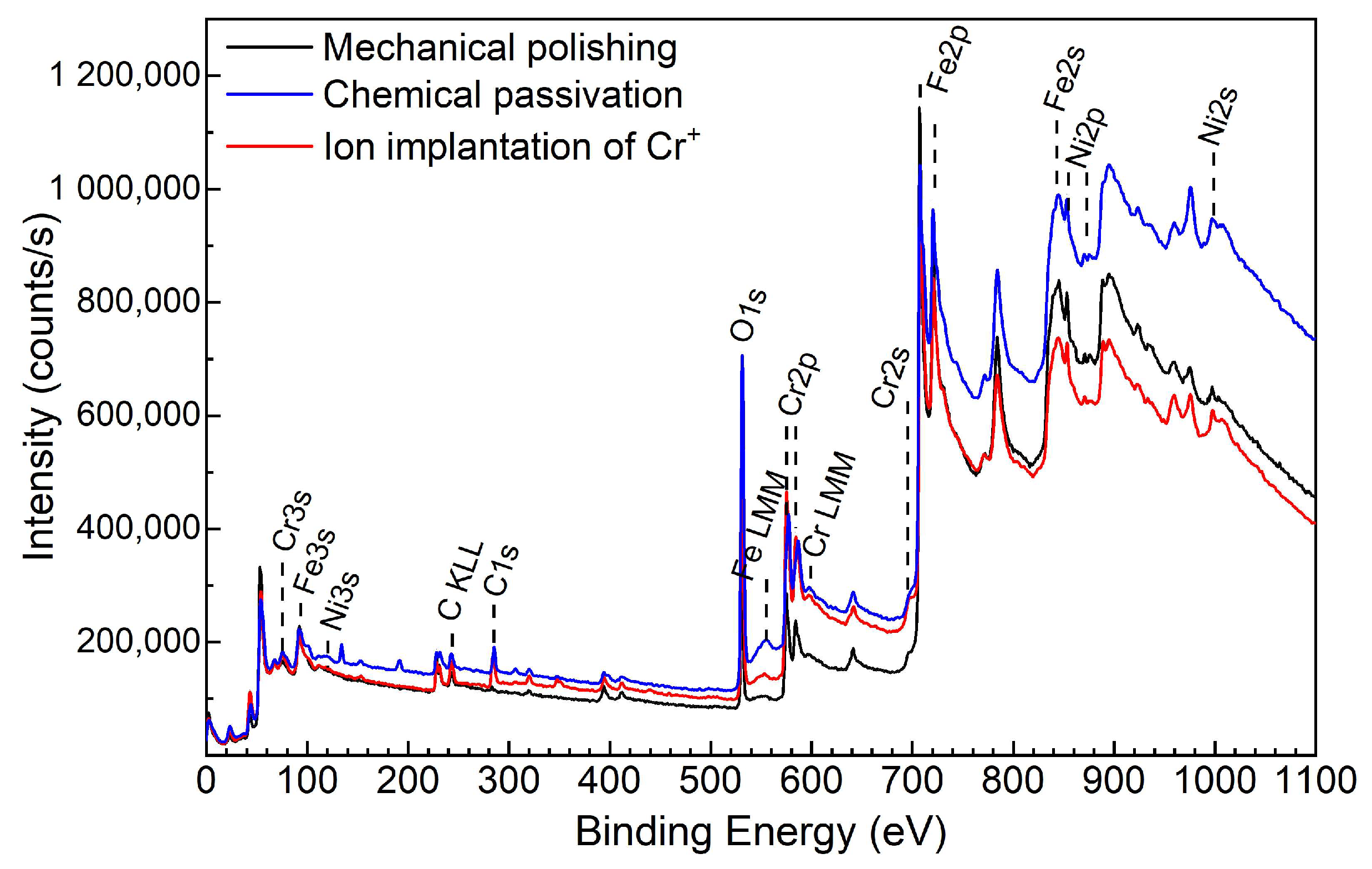
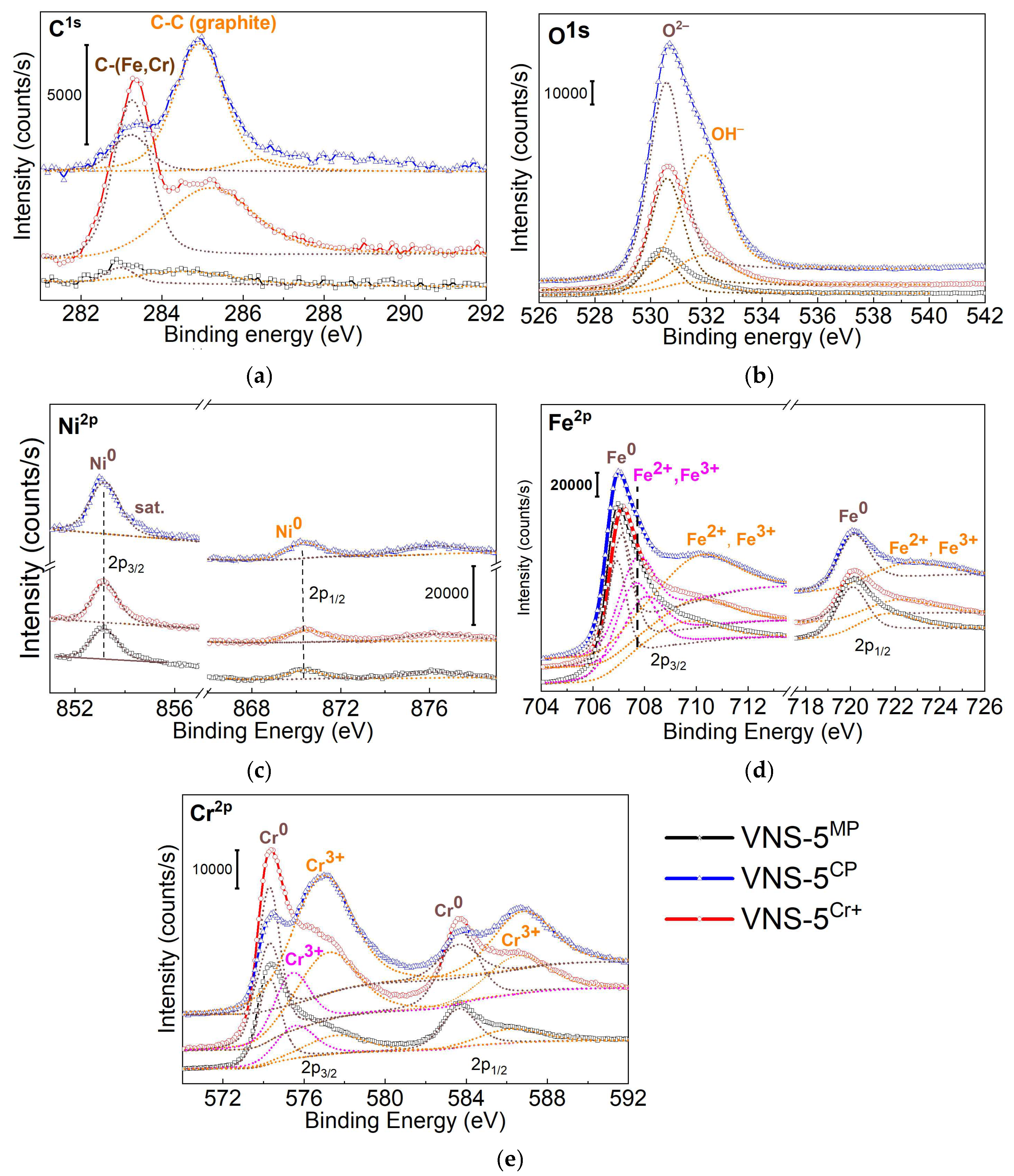
3.3. XPS Study
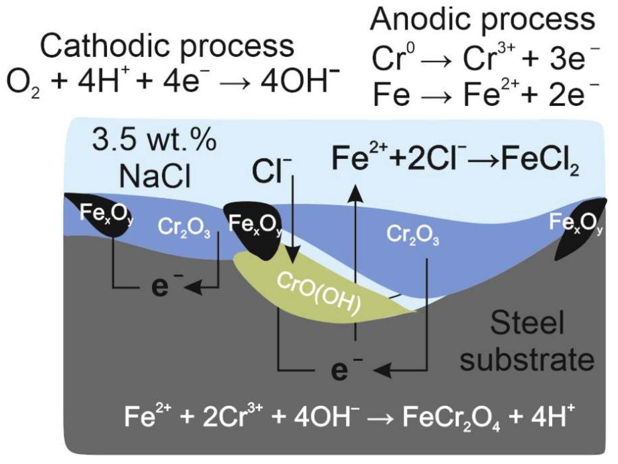
4. Discussion
- (1)
- Fe3O4 + H2O → 3Fe2O3 + 2H+
- (2)
- Fe2O3 + FeCl3 → 3FeOCl
- (3)
- Fe2+ + 2Cr3+ + 4OH− → FeCr2O4 + 4H+
- (4)
- 2Fe3O4 + 2OH− + 2H2O → 6FeOOH + 2e−
- (5)
- 2Fe3O4 + 2OH− → 3Fe2O3 + H2O + 2e−
- (6)
- Cr → Cr3+ + 3e−
- (7)
- 2Cr + 6H2O → Cr2O3 + 3H2O + 6H+ + 6e−
- (8)
- Cr + 3H2O → CrOOH + H2O + 3H+ + e−
- (9)
- CrO + H2O → CrOOH + H+ + e−.
5. Conclusions
- (1).
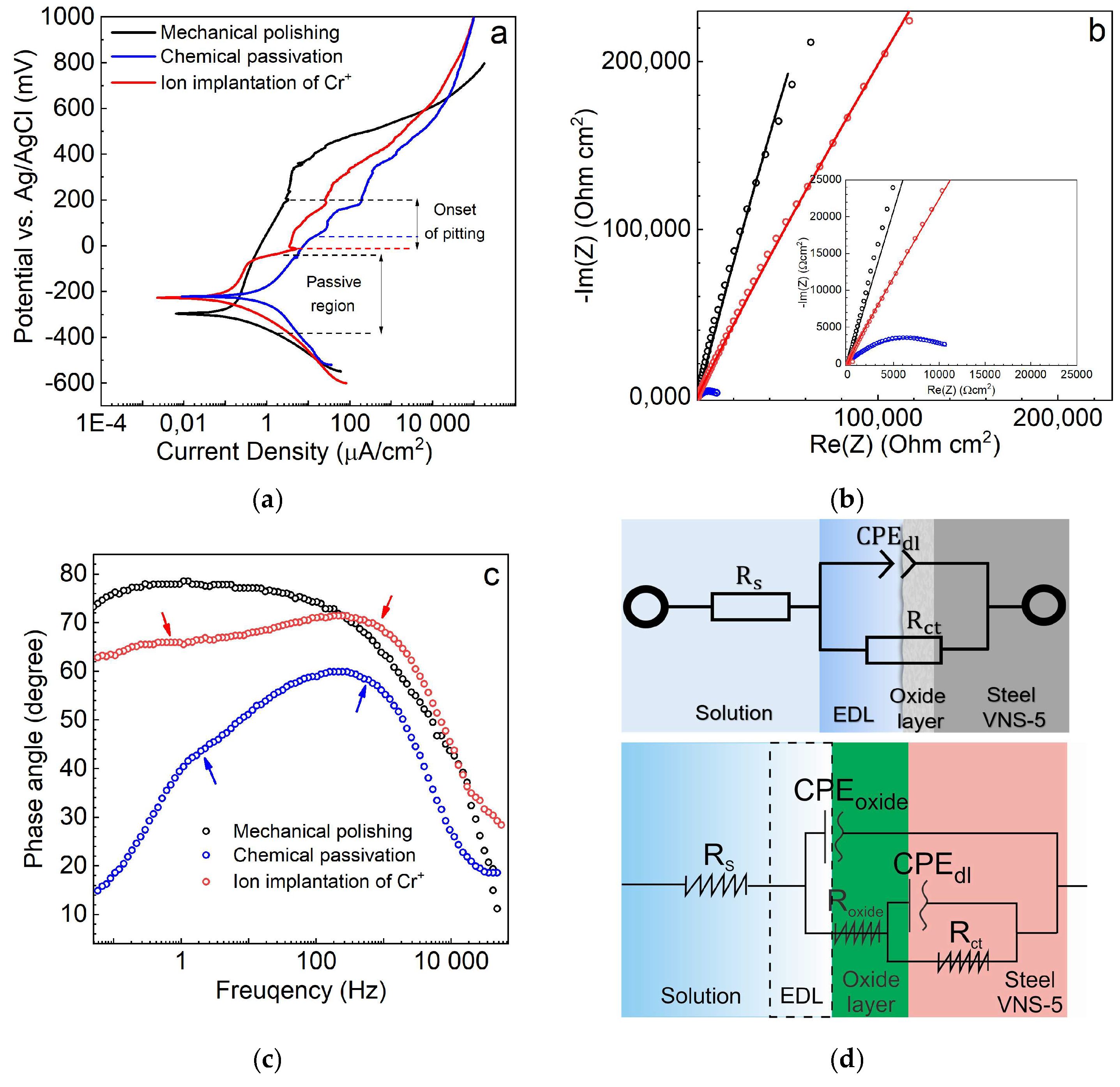
- Based on the EIS results, the mechanically polished and ion beam-treated steels are characterized by the largest values of a charge transfer resistance. In turn, the chemically passivated steel shows a significantly lower (by ~1000-times) resistance and promotes a transfer of charges in seawater (3.5 wt. % NaCl) due to the specific conductivity of the oxide layer.
- (2).
- After the ion beam treatment, the polarization resistance of the steel VNS-5 reaches the highest value, and the estimated corrosion rate via the Stern-Geary equation is ~7.8 times lower than that of the initial (mechanically polished) steel.
- (3).
- After corrosion tests in potentiodynamic mode (in 3.5 wt. % NaCl), the numerous corrosion pits of ~200 μm in diameter are observed on the surface of the steel, notwithstanding the applied surface treatments.
- (4).
- Passivation at various conditions leads to a noticeable change in the ratio of the oxidation species (Cr3+, Fe2+, and Fe3+) in the oxide layers, as confirmed by XPS analysis. It has been found that the oxide layer in the mechanically polished and ion beam-treated steels mainly consists of Fe2O3, Fe3O4, and Cr2O3 oxides and a low amount of CrO(OH) hydroxide, while the chemically passivated steel exhibits Fe2O3 and Fe3O4 oxides and chromium hydroxides.
- (5).
- Using the electrochemical impedance data, the thickness of the electroactive surface layer was evaluated to be ~8.9 nm and ~13.7 nm after chemical passivation and ion implantation, respectively. An improved corrosion performance of the ion beam-treated steel is associated with a better passivation ability of the Cr2O3-rich surface layer.
Author Contributions
Funding
Data Availability Statement
Conflicts of Interest
References
- Parangusan, H.; Bhadra, J.; Al-Thani, N. A review of passivity breakdown on metal surfaces: Influence of chloride- and sulfide-ion concentrations, temperature, and pH. Emergent Mater. 2021, 4, 1187–1203. [Google Scholar] [CrossRef]
- Luo, H.; Li, X.G.; Dong, C.F.; Xiao, K.; Cheng, X.Q. Influence of uv light on passive behavior of the 304 stainless steel in acid solution. J. Phys. Chem. Solids 2013, 74, 691–697. [Google Scholar] [CrossRef]
- Navai, F. Effects of tensile and compressive stresses on the passive layers formed on a type 302 stainless steel in a normal sulphuric acid bath. J. Mater. Sci. 1995, 30, 1166–1172. [Google Scholar] [CrossRef]
- Shimpei, T.; Izumi, M.; Yu, S.; Nobuyoshi, H. Pit initiation on sensitized Type 304 stainless steel under applied stress: Correlation of stress, Cr-depletion, and inclusion dissolution. Corros. Sci. 2020, 167, 108506. [Google Scholar] [CrossRef]
- Wu, J.X.; Wu, Y.Q.; Wang, J.L. Comparative study on corrosion behavior of Cu and Sn under UV light illumination in chloride-containing borate buffer solution. Corros. Sci. 2021, 186, 109471. [Google Scholar] [CrossRef]
- Refait, P.; Grolleau, A.M.; Jeannin, M.; François, E.; Sabot, R. Corrosion of mild steel at the seawater/sediments interface: Mechanisms and kinetics. Corros. Sci. 2018, 130, 76–84. [Google Scholar] [CrossRef]
- Wang, R.; Liu, H.; Hu, D.; Li, D.; Mao, J. Evaluation of notch size effect on LCF life of TA19 specimens based on the stress gradient modified critical distance method. Fatigue Fract. Eng. Mater. Struct. 2018, 41, 1794–1809. [Google Scholar] [CrossRef]
- Xu, S.; Wu, X.Q.; Han, E.H.; Ke, W.; Katada, Y. Crack initiation mechanisms for low cycle fatigue of type 316Ti stainless steel in high temperature water. Mater. Sci. Eng. A 2008, 490, 16–25. [Google Scholar] [CrossRef]
- Unigovski, Y.B.; Lothongkum, G.; Gutman, E.M.; Alush, D.; Cohen, R. Low-cycle fatigue behavior of 316L-type stainless steel in chloride solutions. Corros. Sci. 2009, 51, 3014–3020. [Google Scholar] [CrossRef]
- Zhang, L.; Xiong, X.; Yan, Y.; Gao, K.; Qiao, L.; Su, Y. Atomic modeling for the initial stage of chromium passivation. Int. J. Miner. Metall. Mater. 2019, 26, 732–739. [Google Scholar] [CrossRef]
- Liu, C.; Qi, L.; Shen, T.; Jin, P.; Wang, Z. TEM comparative study on oxide films of 316L and T91 steel exposed to 350–500 °C steam. J. Mater. Sci. Technol. 2024, 175, 10–21. [Google Scholar] [CrossRef]
- Olsson, C.A.; Landolt, D. Passive films on stainless steels—Chemistry, structure and growth. Electrochim. Acta 2003, 48, 1093–1104. [Google Scholar] [CrossRef]
- Liu, X.; Yan, B.; Sun, H. Fatigue Life Prediction of High Strength Steel with Pitting Corrosion under Three-Point Bending Load. Metals 2023, 13, 1839. [Google Scholar] [CrossRef]
- Wang, H.; Dong, H.; Cai, Z.; Liu, Y.; Wang, W. Corrosion fatigue crack growth in stainless steels: A peridynamic study. Int. J. Mech. Sci. 2023, 254, 108445. [Google Scholar] [CrossRef]
- Dwivedi, D.; Lepkova, K.; Becker, T. Carbon steel corrosion: A review of key surface properties and characterization methods. RSC Adv. 2017, 7, 4580. [Google Scholar] [CrossRef]
- Hou, Y.; Zhao, J.; Cao, T.-S.; Zhang, L.; Meng, X.-M.; Zhang, Z.-P. Improvement on the pitting corrosion resistance of 304 stainless steel via duplex passivation treatment. Mater. Corros. 2019, 70, 1764–1775. [Google Scholar] [CrossRef]
- Man, C.; Dong, C.; Cui, Z.; Xiao, K.; Yu, Q.; Li, X. A comparative study of primary and secondary passive films formed on AM355 stainless steel in 0.1 M NaOH. Appl. Surf. Sci. 2018, 427, 763–773. [Google Scholar] [CrossRef]
- Zhang, Y.; Luo, H.; Zhong, Q.; Yu, H.; Lv, J. Characterization of Passive Films Formed on As-received and Sensitized AISI 304 Stainless Steel. Chin. J. Mech. Eng. 2019, 32, 27. [Google Scholar] [CrossRef]
- Samaniego-Gámez, O.; Almeraya-Calderón, F.; Chacón-Nava, J.; Maldonado-Bandala, E.; Nieves-Mendoza, D.; Flores-De los Rios, J.P.; Jáquez-Muñoz, J.M.; Delgado, A.D.; Gaona-Tiburcio, C. Corrosion Behavior of Passivated CUSTOM450 and AM350 Stainless Steels for Aeronautical Applications. Metals 2022, 12, 666. [Google Scholar] [CrossRef]
- Wang, D.; Zhong, Q.; Yang, J.; Zhang, S. Effects of Cr and Ni on the microstructure and corrosion resistance of high-strength low alloy steel. J. Mater. Res. Technol. 2023, 23, 36–52. [Google Scholar] [CrossRef]
- Qin, P.; Ma, H.; Cui, Y.; Liu, R.; Ju, P.; Wang, F.; Liu, L. The corrosion behavior of 316 stainless steel under the cooperative effect of plastic stress and UV illumination in 3.5 wt % NaCl solution. Corros. Sci. 2023, 223, 111466. [Google Scholar] [CrossRef]
- Villegas-Tovar, J.; Gaona-Tiburcio, C.; Lara-Banda, M.; Maldonado-Bandala, E.; Baltazar-Zamora, M.A.; Cabral-Miramontes, J.; Nieves-Mendoza, D.; Olguin-Coca, J.; Estupiñan-Lopez, F.; Almeraya-Calderón, F. Electrochemical Corrosion Behavior of Passivated Precipitation Hardening Stainless Steels for Aerospace Applications. Metals 2023, 13, 835. [Google Scholar] [CrossRef]
- Alliott, G.T.; Higginson, R.L.; Wilcox, G.D. Producing a thin colored film on stainless steels—A review. Part 1: Electrochemical processes. Trans. IMF 2022, 100, 128–137. [Google Scholar] [CrossRef]
- Marikkannu, C.; Sathiyanarayanan, S.; Venkatachari, G. Studies on newer chemical passivation treatment for stainless steel. Trans. Inst. Met. Finish. 2005, 83, 158–160. [Google Scholar] [CrossRef]
- Ma, L.; Pascalidou, E.-M.; Wiame, F.; Zanna, S.; Maurice, V.; Markus, P. Passivation mechanisms and pre-oxidation effects on model surfaces of FeCrNi austenitic stainless steel. Corros. Sci. 2020, 167, 108483. [Google Scholar] [CrossRef]
- Shahini, M.H.; Mohammadloo, H.E.; Ramezanzadeh, B. Recent advances in steel surface treatment via novel/green conversion coatings for anti-corrosion applications: A review study. J. Coat. Technol. Res. 2022, 19, 159–199. [Google Scholar] [CrossRef]
- Dorofeeva, T.; Gubaidulina, T.; Sergeev, V.; Fedorischeva, M. Si-Al-N-O Multi-Layer Coatings with Increased Corrosion Resistance Deposited on Stainless Steel by Magnetron Sputtering. Metals 2022, 12, 254. [Google Scholar] [CrossRef]
- Dorofeeva, T.I.; Gubaidulina, T.A.; Sergeev, V.P.; Kalashnikov, M.P.; Voronov, A.V. Change in the Structure and Corrosion Resistance of a Nickel-Chrome Coating on Stainless Steel During Implantation of High Energy Al+ and B+ Ions. Russ. Phys. J. 2020, 63, 1186–1194. [Google Scholar] [CrossRef]
- Dorofeeva, T.I.; Fedorischeva, M.V.; Gubaidulina, T.A.; Sergeev, O.V.; Sungatulin, A.R.; Sergeev, V.P. Investigation of Corrosion Properties and Composition of the Surface Formed on AISI 321 Stainless Steel by Ion Implantation. Metals 2023, 13, 1468. [Google Scholar] [CrossRef]
- Bystrov, S.; Reshetnikov, S.; Kolotov, A.; Bayankin, V. Changes in the composition and corrosion-electrochemical properties of the chromium-nickel steel 03Cr18Ni11 during implantation of argon, oxygen and nitrogen ions. Phys. Chem. Mater. Treat. 2023, 3, 5–17. [Google Scholar] [CrossRef]
- Zhidkov, M.V.; Gazizova, M.Y.; Ligachev, A.E.; Pavlov, S.K.; Remnev, G.E. Structure and corrosion properties of stainless steel after high-power ion beam processing. IOP Conf. Ser. Mater. Sci. Eng. 2021, 1014, 012061. [Google Scholar] [CrossRef]
- Schoell, R.; Frazer, D.; Zheng, C.; Hosemann, P.; Kaoumi, D. In Situ Micropillar Compression Tests of 304 Stainless Steels After Ion Irradiation and Helium Implantation. JOM 2020, 7, 2778–2785. [Google Scholar] [CrossRef]
- Hardie, C.D.; Williams, C.A.; Xu, S.; Roberts, S.G. Effects of irradiation temperature and dose rate on the mechanical properties of self-ion implanted Fe and Fe–Cr alloys. J. Nucl. Mater. 2013, 439, 33–40. [Google Scholar] [CrossRef]
- Smidt, F.A. Use of ion beam assisted deposition to modify the microstructure and properties of thin films. Int. J. Mater. Rev. 1990, 35, 61–125. [Google Scholar] [CrossRef]
- Jain, I.P.; Agarwal, G. Ion beam induced surface and interface engineering. Surf. Sci. Rep. 2011, 66, 77–172. [Google Scholar] [CrossRef]
- Feng, K.; Wang, Y.; Li, Z.; Chu, P.K. Characterization of carbon ion implantation induced graded microstructure and phase transformation in stainless steel. Mater. Charact. 2015, 106, 11–19. [Google Scholar] [CrossRef]
- Cao, Z.; Liang, X.; Luo, S.; Song, J.; Pu, C.; Pang, Z.; He, W. Improvement of nitrogen ion implantation on the wear and corrosion resistance of bearing steel in NaCl solution. Vacuum 2024, 222, 112995. [Google Scholar] [CrossRef]
- Semin, V.O.; D’yachenko, F.A.; Erkovich, A.V.; Ostapenko, M.G.; Chernova, A.P.; Shulepov, I.A.; Savkin, K.P.; Khabibova, E.D.; Yuzhakova, S.I.; Meinser, L.L. Characterization of corrosion properties, structure and chemistry of titanium-implanted TiNi shape memory alloy. Mater. Charact. 2023, 206, 113457. [Google Scholar] [CrossRef]
- Semin, V.O.; Chernova, A.P.; Erkovich, A.V.; Ostapenko, M.G.; D’yachenko, F.A.; Savkin, K.P.; Khabibova, E.D.; Meisner, L.L. Electrochemical Properties and Structure of the TiNi Alloy Surface Layers Implanted with Titanium and Niobium Ions. Inorg. Mater. Appl. Res. 2024, 15, 636–648. [Google Scholar] [CrossRef]
- Wang, F.; Zhou, C.; Zheng, L.; Zhang, H. Corrosion resistance of carbon ion-implanted M50NiL aerospace bearing steel. Prog. Nat. Sci. Mater. Int. 2017, 27, 615–621. [Google Scholar] [CrossRef]
- Murphy, M.E.; Insley, G.M.; Laugier, M.T.; Newcom, S.B. Microstructural characterization of carbon implanted austenitic stainless steel. Nucl. Instrum. Methods Phys. Res. B 2005, 234, 256–260. [Google Scholar] [CrossRef]
- Qin, Z.; Wu, Z.; Zen, X.; Luo, Q.; Liu, L.; Lu, W.; Hu, W. Improving Corrosion Resistance of a Nickel-Aluminum Bronze Alloy via Nickel Ion Implantation. Corrosion 2016, 72, 1269–1280. [Google Scholar] [CrossRef] [PubMed]
- Meisner, L.; Lotkov, A.; Sivokha, V.P.; Rotshtein, V.; Barmina, E.; Girjakova, Y.L. Structural-phase condition, unelastic and plastic behavior and nanohardness of the TiNi surface layers modified by an ion- and electron irradiation. Mater. Sci. Eng. A 2006, 438–440, 558–562. [Google Scholar] [CrossRef]
- Qin, Z.; Luo, Q.; Zhang, Q.; Wu, Z.; Liu, L.; Shen, B.; Hu, W. Improving corrosion resistance of nickel-aluminum bronzes by surface modification with chromium ion implantation. Surf. Coat. Technol. 2018, 334, 402–409. [Google Scholar] [CrossRef]
- Ettefagh, A.H.; Guo, S.; Raush, J. Corrosion performance of additively manufactured stainless steel parts: A review. Addit. Manuf. 2021, 37, 101689. [Google Scholar] [CrossRef]
- Dorofeeva, T.; Semin, V.; Gubaidulina, T.; Voronov, A.; Ngo, B.; Sergeev, V. Structure and corrosion properties of multilayer metal/nitride/oxide ceramic coatings formed on austenitic martensitic steel by magnetron deposition. Thin Solid Film. 2024, 798, 140380. [Google Scholar] [CrossRef]
- Shandrikov, M.V.; Cherkasov, A.A.; Oks, E.M.; Vizir, A.V.; Zolotukhin, D.B. Low-pressure high-current pulsed magnetron discharge with electron injection from a vacuum arc plasma emitter. Vacuum 2024, 219, 112721. [Google Scholar] [CrossRef]
- Oks, E.M.; Anders, A. Evolution of the plasma composition of a high power impulse magnetron sputtering system studied with a time-of-flight spectrometer. J. Appl. Phys. 2009, 105, 093304. [Google Scholar] [CrossRef]
- Oks, E.M.; Anders, A. A self-sputtering ion source: A new approach to quiescent metal ion beams. Rev. Sci. Instrum. 2010, 81, 02B306. [Google Scholar] [CrossRef]
- Zhang, H.X.; Zhang, X.J.; Zhou, F.S.; Li, Q.; Liu, F.H.; Han, Z.E.; Lin, W.L. Mevva ion source for the application of material surface modification. Rev. Sci. Instrum. 1994, 65, 1295–1297. [Google Scholar] [CrossRef]
- Savkin, K.P.; Oks, E.M.; Yushkov, G.Y. Mass-to-charge composition of high-current vacuum arc plasmas with Cu-Cr cathodes. Plasma Sources Sci. Technol. 2019, 28, 065008. [Google Scholar] [CrossRef]
- Shandrikov, M.V.; Cherkasov, A.A.; Oks, E.M. Parameters and ion mass-to-charge composition of a high-power impulse magnetron discharge with electron injection. Vacuum 2022, 200, 111056. [Google Scholar] [CrossRef]
- Stern, M.; Geary, A.L. Electrochemical polarization. I. A, Theoretical analysis of the shape of polarization curves. J. Electrochem. Soc. 1957, 104, 33–63. [Google Scholar] [CrossRef]
- Jie, Z.; Zhang, Z.; Susmel, L.; Zhang, L.; Lu, W. Corrosion fatigue mechanisms and evaluation methods of high-strength steel wires: A state-of-the-art review. FFEMS 2024, 47, 2287–2318. [Google Scholar] [CrossRef]
- Liu, J.; Wei, L.; Cui, Q.; Shu, H.; Peng, W.; Gong, H.; Xue, Y.; Han, M. Chloride Corrosion Resistance of Steel Fiber-Reinforced Concrete and Its Application in Subsea Tunnel Linings. Coatings 2025, 15, 235. [Google Scholar] [CrossRef]
- Abbas, M.; Haider, S.; Rizvi, M.; Sarfraz, S.; Raza, A.; Khan, A.; Loya, A.; Najib, A. Evaluation of the influence of dissolved nitrates on corrosion behavior of ship structural steel exposed to seawater environment. Ocean Eng. 2024, 298, 117268. [Google Scholar] [CrossRef]
- NIST. NIST X-Ray Photoelectron Spectroscopy Database; National Institute of Standards and Technology: Gaithersburg, MD, USA, 2000; p. 20899. [Google Scholar] [CrossRef]
- Hughes, A.E.; Easton, C.D.; Gengenbach, T.R.; Biesinger, M.C.; Laleh, M. Interpretation of complex X-ray photoelectron peak shapes. I. Case study of Fe 2p3/2 spectra. J. Vac. Sci. Technol. A 2024, 42, 053205. [Google Scholar] [CrossRef]
- Hughes, A.E.; Easton, C.D.; Gengenbach, T.R.; Biesinger, M.C.; Laleh, M. Interpretation of complex X-ray photoelectron peak shapes. II. Case study of Fe 2p3/2 fitting applied to austenitic stainless steels 316 and 304. J. Vac. Sci. Technol. A 2024, 42, 053206. [Google Scholar] [CrossRef]
- Hwang, H.-K.; Kim, S.-J. Electrochemical properties in natural seawater of super austenitic stainless steel with plasma ion nitriding and electropolishing. Surf. Coat. Technol. 2024, 483, 130748. [Google Scholar] [CrossRef]
- Colombo, D.; Carro, I.; Catellani, C.; Ceré, S. Electropolishing of AISI 316L: Effect on surface characteristics and corrosion behavior. Int. J. Adv. Manuf. Technol. 2024, 130, 4207–4219. [Google Scholar] [CrossRef]
- Cabezon, C.G.; Castro Sastre, M.A.; Fernandez Abia, A.I.; Rodriguez Mendez, M.L.; Pedrosa, F.M. Microstructure–Hardness–Corrosion Performance of 17–4 Precipitation Hardening Stainless Steels Processed by Selective Laser Melting in Comparison with Commercial Alloy. Met. Mater. Int. 2022, 28, 2652–2667. [Google Scholar] [CrossRef]
- He, S.; Jiang, D. Electrochemical behavior and properties of passive films on 304 stainless steel under high temperature and stress conditions. Int. J. Electrochem. Sci. 2018, 13, 5832–5849. [Google Scholar] [CrossRef]
- Zhou, Z.; Liu, B.; Guo, W.; Fu, A.; Duan, H.; Li, W. Corrosion behavior and mechanism of FeCrNi medium entropy alloy prepared by powder metallurgy. J. All. Comp. 2021, 867, 159094. [Google Scholar] [CrossRef]
- Biesinger, M.C.; Brown, C.; Mycroft, J.R.; Davidson, R.D.; McIntyre, N.S. X-ray photoelectron spectroscopy studies of chromium compounds. Surf. Interface Anal. 2004, 36, 1550–1563. [Google Scholar] [CrossRef]
- Orazem, M.E.; Frateur, I.; Tribollet, B.; Vivier, V.; Marcelin, S.; Pébère, N.; Bunge, A.L.; White, E.A.; Riemer, D.P.; Musiani, M. Dielectric Properties of Materials Showing Constant-Phase-Element (CPE) Impedance Response. J. Electrochem. Soc. 2013, 160, C215. [Google Scholar] [CrossRef]
- Fang, P.H.; Brower, W.S. Dielectric Constant of Cr2O3 Crystals. Phys. Rev. 1963, 129, 1561. [Google Scholar] [CrossRef]
- Iwauchi, K.; Kita, Y.; Koizumi, N. Magnetic and dielectric properties of Fe3O4. J. Phys. Soc. Jpn. 1980, 49, 1328–1335. [Google Scholar] [CrossRef]
- Filius, J.D.; Lumsdon, D.G.; Meeussen, J.C.L.; Hiemstra, T.; van Riemsdijk, W.H. Adsorption of fulvic acid on goethite. Geochim Cosmochim Acta 2000, 64, 51–60. [Google Scholar] [CrossRef]
- Akhtar, M.J.; Tiwari, N.K.; Devi, J.; Mahmoud, M.; Link, G.; Thumm, M. Determination of Effective Constitutive Properties of Metal Powders at 2.45 GHz for Microwave Processing Applications. Frequenz 2014, 68, 69–81. [Google Scholar] [CrossRef]
- Bystrov, S.G.; Reshetnikov, S.M.; Borisov, E.M.; Klimova, I.N.; Kolotov, A.A.; Zhikharev, A.V.; Bayankin, V.Y. Effect of Implantation of Argon and Oxygen Ions on the Physicochemical Properties and Corrosion and Electrochemical Behavior of 14Cr17Ni2 Chromium–Nickel Steel. Inorg. Mater. Appl. Res. 2022, 13, 666–673. [Google Scholar] [CrossRef]
- Feng, H.; Dai, J.; Li, H.-B.; Jiang, Z.-H.; Qu, J.-D.; Zhao, Y.; Zhang, S.-C.; Zhang, T. Sn microalloying enhances corrosion resistance of stainless steel by accelerating heterogeneous nucleation of passive film. Corros. Sci. 2022, 201, 110279. [Google Scholar] [CrossRef]
- Terachi, T.; Yamada, T.; Miyamoto, T.; Arioka, K.; Fukuya, K. Corrosion Behavior of Stainless Steels in Simulated PWR Primary Water–Effect of Chromium Content in Alloys and Dissolved Hydrogen. J. Nucl. Sci. Technol. 2008, 45, 975–984. [Google Scholar] [CrossRef]
- Reformatskaya, I.I.; Podobaev, A.N.; Trofimova, E.V.; Ashcheulova, I.I. Development of ideas about the role of chromium in the processes of passivation and pitting corrosion of Fe-Cr alloys. Prot. Met. 2004, 40, 229–235. (In Russian) [Google Scholar] [CrossRef]
- Ha, H.-Y.; Kim, K.-W.; Park, S.-J.; Lee, T.-H.; Park, H.; Moon, J.; Hong, H.-U.; Lee, C.-H. Effects of Cr on pitting corrosion resistance and passive film properties of austenitic Fe-19Mn-12Al-1.5 C lightweight steel. Corros. Sci. 2022, 206, 110529. [Google Scholar] [CrossRef]
- Hermas, A.A. XPS analysis of the passive film formed on austenitic stainless steel coated with conductive polymer. Corros. Sci. 2008, 50, 2498–2505. [Google Scholar] [CrossRef]
- Örnek, C.; Payam, B.; Gloskovskii, A.; Kazmanlı, K.; Mohamed, N.; Derin, B.; Ürgen, M.; Chou, C.; Yen, H.-W.; Avcı, B.; et al. Understanding the passive behavior of low-chromium high strength Hybrid steel in corrosive environments. NPJ Mater. Degrad. 2023, 7, 71. [Google Scholar] [CrossRef]
- Jiménez-Come, M.J.; Turias, I.J.; Ruiz-Aguilar, J.J.; Trujillo, F.J. Breakdown potential modelling of austeniticstainless steel. J. Chemom. 2014, 28, 181–191. [Google Scholar] [CrossRef]
- Shibaeva, T.; Laurinavichyute, V.; Tsirlina, G.; Arsenkin, A.; Grigorovich, K. The effect of microstructure and non-metallic inclusions on corrosion behavior of low carbon steel in chloride containing solutions. Corros. Sci. 2014, 80, 299–308. [Google Scholar] [CrossRef]

| C | S | P | Mn | Cr | Si | Ni | N | B | Mo | Fe |
|---|---|---|---|---|---|---|---|---|---|---|
| 0.11–0.16 | ≤0.02. | ≤0.03 | ≤1 | 14–15 | ≤0.7 | 4–5 | 0.05–0.11 | 0.11–0.16 | 2.3–2.8 | balance |
| Mechanical Polishing | Chemical Passivation | Ion Implantation | |
|---|---|---|---|
| Corrosion current density, μA/cm2 | 0.583 | 0.513 | 0.045 |
| Corrosion potential, mV | –294 | –222 | –227 |
| Polarization resistance, MΩ·cm2 | 0.038 | 0.055 | 0.296 |
| Solution resistance, Ω·cm2 | 7 | 15 | 16 |
| Oxide resistance, Ω·cm2 | – | 3150 | 39,180 |
| Charge transfer resistance, Ω·cm2 | 9.66 × 10⁶ | 9939 | 2.18 × 10⁷ |
| Constant phase element of oxide, Ω−1cm2s−n | – | 2.60 × 10⁻⁵ | 6.13 × 10⁻⁶ |
| Constant phase element of the double layer, Ω−1cm2s−n | 1.34 × 10⁻⁵ | 4.46 × 10⁻⁵ | 2.96 × 10⁻⁶ |
| Surface Treatment | Constituent | Peak Energy, eV | Chemical State |
|---|---|---|---|
| Mechanical polishing | C 1s O 1s Ni 2p3/2 Ni 2p1/2 Fe 2p3/2 Cr 2p3/2 | 283.0 284.5 530.4 531.5 853.2 870.4 706.9 707.7 709.8 574.3 575.7 577.7 | C-(Fe, Cr) in γ-(Fe,Cr,Ni) phase C-C (graphite) O2– in oxide phase OH− Ni0 (metallic) Ni0 (metallic) Fe0 (metallic) Fe2+ and Fe3+ in Fe3O4 Fe2+ and Fe3+ in Fe2O3 Cr0 (metallic) Cr3+ in Cr2O3 Cr3+ in CrO(OH), Cr(OH)3 |
| Chemical passivation | C 1s O 1s Ni 2p3/2 Ni 2p1/2 Fe 2p3/2 Cr 2p3/2 | 283.2 284.9 530.6 531.9 853.2 870.4 706.9 707.8 709.9 574.3 577.0 | C-(Fe, Cr) in γ-(Fe,Cr,Ni) phase C-C (graphite) O2– in oxide phase OH− Ni0 (metallic) Ni0 (metallic) Fe0 (metallic) Fe2+ and Fe3+ in Fe3O4 Fe2+ and Fe3+ in Fe2O3 Cr0 (metallic) Cr3+ in CrO(OH), Cr(OH)3 |
| Ion implantation | C 1s O 1s Ni 2p3/2 Ni 2p1/2 Fe 2p3/2 Cr 2p3/2 | 283.3 285.2 530.6 531.9 853.2 870.5 707.1 708.1 710.2 574.3 575.5 577.3 | C-(Fe, Cr) in γ-(Fe,Cr,Ni) phase C-C (graphite) O2– in oxide phases OH− Ni0 (metallic) Ni0 (metallic) Fe0 (metallic) Fe2+ and Fe3+ in Fe3O4 Fe2+ and Fe3+ in Fe2O3 Cr0 (metallic) Cr3+ in Cr2O3 Cr3+ in CrO(OH), Cr(OH)3 |
| Compound/Material | ε | Ref. |
|---|---|---|
| Cr2O3 | ~13 | [67] |
| Fe2O3 | ~12 | [68] |
| Fe3O4 | ~20 | |
| FeO(OH) | ~11 | [69] |
| Stainless steel | ~12 | [70] |
| Surface Treatment | Fe0, % | Fe2 and Fe3+, % | Cr0, % | Cr3+, % | Ni0, % | δ, nm |
|---|---|---|---|---|---|---|
| Mechanical polishing | 27 | 57 | 5 | 7 | 4 | N/A |
| Chemical passivation | 24 | 45 | 5 | 23 | 3 | ~8.9 |
| Ion implantation | 21 | 43 | 11 | 21 | 4 | ~13.7 |
Disclaimer/Publisher’s Note: The statements, opinions and data contained in all publications are solely those of the individual author(s) and contributor(s) and not of MDPI and/or the editor(s). MDPI and/or the editor(s) disclaim responsibility for any injury to people or property resulting from any ideas, methods, instructions or products referred to in the content. |
© 2025 by the authors. Licensee MDPI, Basel, Switzerland. This article is an open access article distributed under the terms and conditions of the Creative Commons Attribution (CC BY) license (https://creativecommons.org/licenses/by/4.0/).
Share and Cite
Semin, V.; Cherkasov, A.; Savkin, K.; Shandrikov, M.; Khabibova, E. Corrosion Performance of Chemically Passivated and Ion Beam-Treated Austenitic–Martensitic Steel in the Marine Environment. J. Manuf. Mater. Process. 2025, 9, 167. https://doi.org/10.3390/jmmp9050167
Semin V, Cherkasov A, Savkin K, Shandrikov M, Khabibova E. Corrosion Performance of Chemically Passivated and Ion Beam-Treated Austenitic–Martensitic Steel in the Marine Environment. Journal of Manufacturing and Materials Processing. 2025; 9(5):167. https://doi.org/10.3390/jmmp9050167
Chicago/Turabian StyleSemin, Viktor, Alexander Cherkasov, Konstantin Savkin, Maxim Shandrikov, and Evgeniya Khabibova. 2025. "Corrosion Performance of Chemically Passivated and Ion Beam-Treated Austenitic–Martensitic Steel in the Marine Environment" Journal of Manufacturing and Materials Processing 9, no. 5: 167. https://doi.org/10.3390/jmmp9050167
APA StyleSemin, V., Cherkasov, A., Savkin, K., Shandrikov, M., & Khabibova, E. (2025). Corrosion Performance of Chemically Passivated and Ion Beam-Treated Austenitic–Martensitic Steel in the Marine Environment. Journal of Manufacturing and Materials Processing, 9(5), 167. https://doi.org/10.3390/jmmp9050167