1. Introduction
The hard turning process has the potential to replace cylindrical grinding for the machining of heat-treated steels, offering numerous advantages in industrial applications. These benefits include reduced tool cost, enhanced material removal rate, lower investment in machinery, the capability to perform multiple operations in a single setup, greater flexibility for machining complex geometries, suitability for interrupted cutting, minimized residual stresses, and enhanced dimensional accuracy, as well as increased process reliability [
1]. Among various materials in the hard turning process, martensitic stainless steels are distinguished by their high chromium content, typically exceeding 12%. This characteristic makes them ideal for applications where moderate corrosion resistance up to temperatures of 650 °C, combined with good tensile strength, creep, and fatigue resistance, is required [
2]. However, the high amount of chromium reduces the thermal conductivity of the material, leading to heat concentration at the cutting zone. This can accelerate tool wear and cause thermal damage [
3]. For hardened martensitic stainless steels, the grinding process is generally used to achieve high surface finishes [
4]. Ongoing efforts are focusing on replacing the grinding process with hard turning, thereby enabling the machining of parts with more complex geometries and achieving a higher material removal rate [
5].
In a study by S. Kokkirala et al. [
6], the influence of various cutting parameters on the surface integrity of AISI 52100 martensitic bearing steel during hard turning was examined. The research evaluated the effects of cutting speed, feed rate, and depth of cut on the characteristics of the machined surface, including surface roughness, microhardness, residual stresses, and microstructural alterations. Lower feed rates and optimized cutting speeds were found to result in smoother surface finishes by minimizing the scallop height and machining forces. The intense localized heating and cooling during cutting can induce phase transformations in the material, leading to the formation of a white layer composed of martensite or retained austenite. Higher cutting speeds are known to elevate temperature, thus increasing the likelihood of white layer formation due to more significant thermal effects [
7].
S.B. Hosseini and U. Klement [
8] investigated the formation of the white layer during the hard turning of AISI 52100 bearing steel. The findings demonstrated that the development of the white layer was influenced by a combination of thermal, mechanical, and metallurgical factors, including high temperatures, severe plastic deformation, and rapid cooling rates. The study discussed the impact of cutting parameters and material properties on the thickness and microhardness of the white layer.
Using response surface methodology (RSM) and artificial neural networks (ANNs), Zerti et al. [
9] showed significant improvements in the machining process, so that the surface finish quality was improved and tool wear was reduced. The impact of cutting speed, feed rate, depth of cut, and tool geometry on the surface roughness was analyzed, revealing that the selection of optimal parameters resulted in significant improvements in the surface finish.
Currently, cubic boron nitride (CBN) inserts are widely used in the hard turning of hardened steels [
10]. The CBN inserts offer superior thermal and chemical stability, leading to extended tool life [
11]. Such inserts ensure that geometric and dimensional tolerances remain unaffected over time, even under challenging machining conditions [
12]. R. Bag et al. [
13] focused on the characteristics of cutting inserts and the effects of coatings during the hard turning of AISI 4340 martensitic steel, emphasizing that tool material and coatings play a critical role in enhancing machining performance, particularly in terms of wear resistance and surface finish quality.
However, the challenge of achieving high precision in hard turning remains, as the phenomenon of elastic deformation significantly affects geometric and dimensional accuracy, especially in micro-tolerances [
14]. Elastic deformation occurs when the material under the insert tip is elastically deformed, and then followed by plastic deformation, which separates the chip from the workpiece. After chip separation, the release of the cutting load allows the material to deform. This phenomenon of elastic deformation contributes to dimensional deviations in hard-turned components, which is particularly undesirable in applications with high precision. The magnitude of the elastic deformation is related to the material’s stress–strain characteristics [
15]. This elastic deformation effect can cause continuous rubbing of the work material against the cutting tool, leading to high contact stresses, dimensional inaccuracies, and surface deterioration, as well as extra tool wear. In hard turning, the material strength of hardened steels plays a key role in the occurrence of this elastic deformation [
16]. It has been found that the elastic deformation is considerably higher in quenched materials compared to annealed ones.
Another challenge that may limit the hard turning process is machining interrupted surfaces [
17], which can lead to increased tool wear and deteriorated surface quality. In such conditions, the low fracture toughness of ceramic tools makes them susceptible to failure under interrupted cutting conditions [
18]. While CBN inserts are preferred in such cases, they are also prone to failure when exposed to high-impact oscillations. These tools may not withstand the mechanical shocks generated during interrupted cutting. Since interrupted surfaces are often possible in the turning process, the study of the hard turning of such surfaces becomes crucial. One traditional approach to protect the cutting edge against failure is to distribute the machining forces over a larger cutting edge, achieved by increasing the approach angle of the insert [
19]. However, this approach is not practical for machining complex contours, where the approach angle continuously varies. Therefore, other auxiliary techniques could be explored to balance these limitations and enhance the efficiency of the hard turning process. M. Kam [
20] investigated the impact of deep cryogenic treatment during dry turning. The results demonstrated that deep cryogenic treatment significantly enhances the hardness of the steel, thereby improving its machinability. This increased hardness results from microstructural refinement, particularly the formation of finer martensite and carbides, which finally led to better surface finish.
As another auxiliary technique, a localized pre-heating of the workpiece material ahead of the cutting tool with a laser was utilized to soften the material, reducing machining forces and tool wear during hard turning [
21,
22].
While the aforementioned methods offer partial improvements in the process efficiency of hard turning, a key research question arises regarding how another auxiliary technique like laser structuring can be effectively implemented in the hard turning process to enhance performance and mitigate existing challenges. This study proposes a novel approach to laser structuring and the turning process. Before the turning operation, steep axial grooves are created along the workpiece circumference using an ultrashort pulse laser. Then, a subsequent turning is performed. This method has already demonstrated its potential in machining non-hardened stainless steel, showing promising results in terms of chip breaking and process efficiency [
23]. The primary focus of this investigation is to evaluate machining forces and surface quality for hardened stainless steel. It should be noted that in the conventional laser-assisted turning, the laser typically heats the workpiece surface near the cutting tool to soften the material and reduce machining forces. However, in the proposed method in this paper, the laser’s role is limited to generating axial grooves for an interrupted machining. Based on the literature review, no previous study on the hard turning process has proposed a method similar to the one described in this study. The results showed that laser structuring affected machining forces. In addition, the laser structuring demonstrated potential for optimizing chip breaking.
2. Experimental Setup
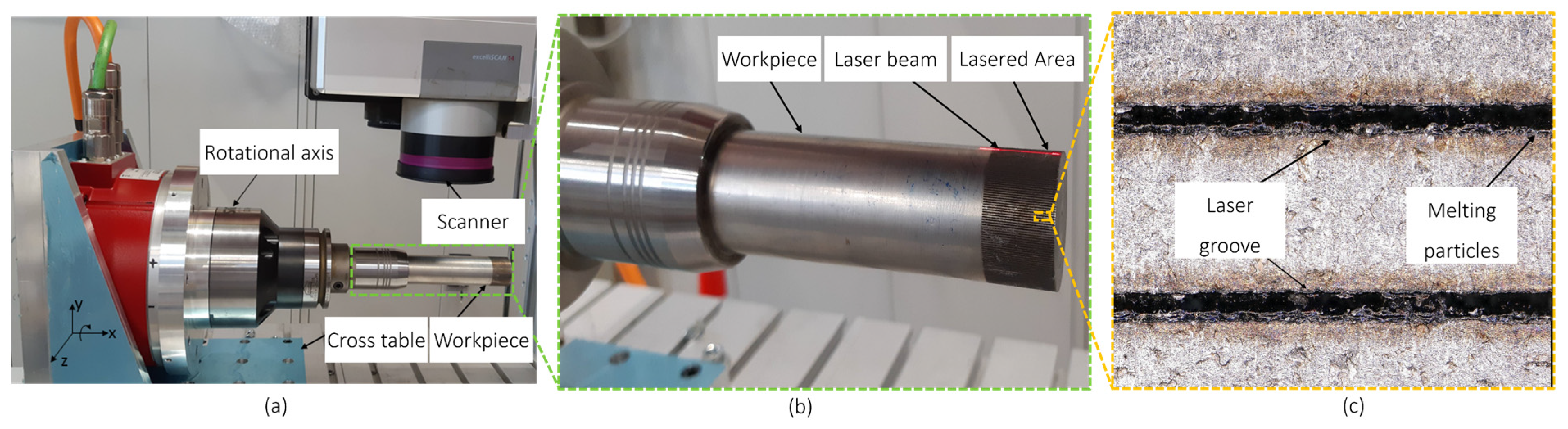
For the laser structuring of the samples, a picosecond laser was integrated into a customized machine (ISEL Machine). The machine provided a movement system in three main directions between X, Y, and Z through a cross-table. On the X-Y table, a rotational axis was installed, which provided the rotational movements required for the laser structuring of the workpiece’s circumference.
Figure 1a illustrates the clamping and movement system. The rotary axis was equipped with an HSK-clamp with a 0.01 mm round-out, and a minimum rotational resolution of 0.4°, ensuring accurate and equal spacing between laser grooves. A laser scanner (ScanLab ExcelliScan 14; ScanLab GmbH, Pchheim, Germany) was installed on this machine to move the beam along a line in the X-direction.
The selected material for this study was DIN 1.4034, a martensitic stainless steel known for its high hardness, wear resistance, and good corrosion resistance, making it desirable for various industrial applications. The material was hardened to 60HRC. The workpiece’s initial diameter was 30 mm. As
Figure 1b illustrates, laser structuring was performed on the hardened workpieces along a straight line (along with the workpiece longitudinal axes with the length of 30 mm) with two different numbers of axial laser grooves,
n = 180 and
n = 300, on the circumference. Increasing the number of laser grooves decreased the distance between two tandem axial grooves (
Figure 1c). Based on an initial parameter screening, the selected laser parameters for structuring were as follows: 40 W average power, 400 kHz frequency, 500 mm/s scanning speed, 35 repetitions, and the focus point on the surface. An F-theta lens with a focus length of 100 mm was utilized. Following the laser structuring, a laser groove depth of 92 µm was achieved. Since this material contains a considerable percentage of chromium elements, the laser ablation process included some melted particles inside the axial groove and on the surface (
Figure 1c), which hindered the ablation process from achieving higher ablation depths. A cross-section of the laser groove is shown in
Figure 2, highlighting the groove dimensions as well as the heat-affected zone.
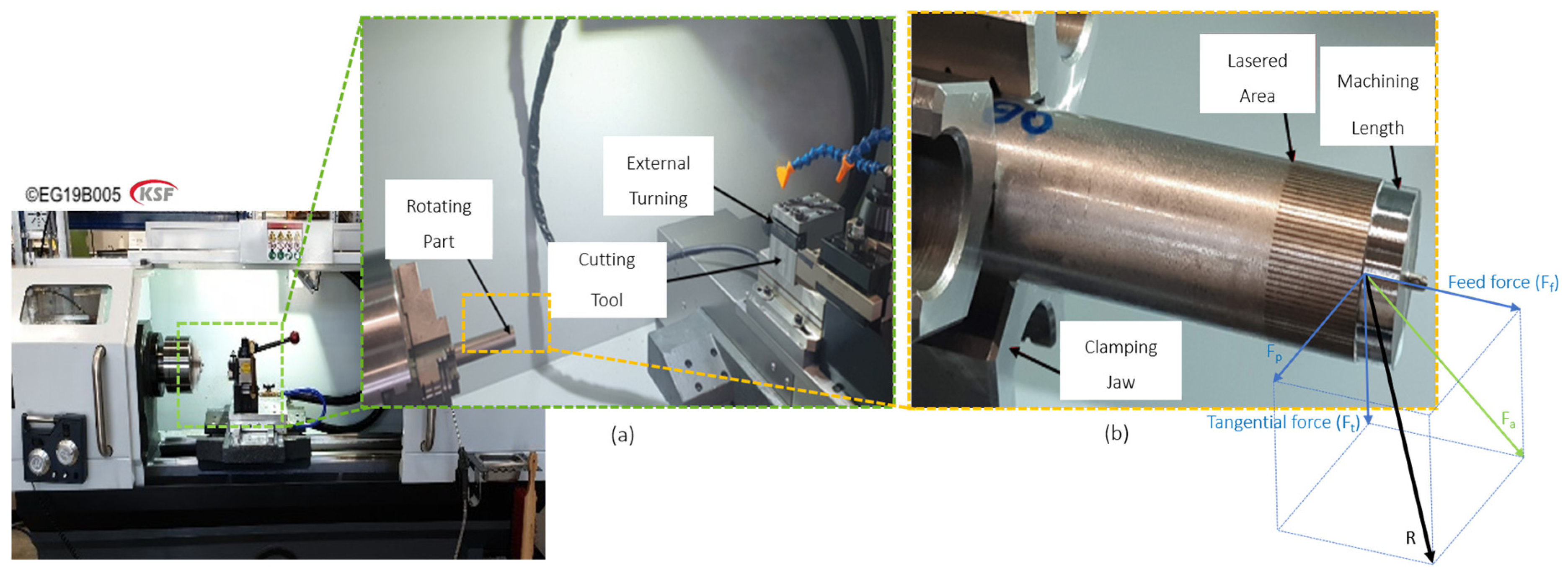
The turning experiments were conducted using a CNC lathe (from Haas Automation, Inc._Model: TL-1; Oxnard, CA, USA) (
Figure 3). To comprehensively analyze the machining forces involved during the machining process, both tangential and feed forces were measured. Each measurement was performed three times to ensure the repeatability and reliability of the results. For this purpose, a dynamometer (Kistler Instrumente AG.-Type: 9257B; Amherst, NY, USA) was mounted on the machine carriage, ensuring accurate data acquisition.
The machining parameters were adopted within the recommendation range of the utilized insert (Manufacture: Paul Horn GmbH -the code of CBN insert: CCGW09T302). The initial machining trials were performed on the non-structured workpieces to establish reference data. The subsequent machining experiments were conducted on the laser-structured workpieces under the same conditions to make a comparative analysis possible. Input parameters such as depth of cut (a
p), feed rate (f), cutting velocity (v
c), approach angle (κ), and the number of axial laser grooves (n) were systematically varied to evaluate their influence on the machining forces. The machining conditions for the non-structured and laser-structured workpieces are detailed in
Table 1 and
Table 2.
3. Results
The primary effects of the input parameters on the machining forces are illustrated in
Figure 4. The tangential forces consistently exhibited higher magnitudes compared to the feed forces. This difference was particularly pronounced for a
p = 70 µm. For κ = 50°, when the approach angle becomes smaller, the chip thickness decreases; therefore, the feed forces also decrease. It was observed that the test with a
p = 320 µm exhibited the highest values for the machining forces. Therefore, these two approach angles and depths of cut were selected as pilot tests to evaluate the effect of laser structuring. The laser parameters mentioned above were applied for laser structuring.
Figure 5 compares the machining forces between the laser-structured and non-structured workpieces for both κ = 50° and κ = 90°. An increase was observed in the machining forces for the laser-structured samples at both approach angles. This may be attributed to the material alteration caused by the laser ablation. For the parts with more axial laser grooves, the material alteration could be more significant. The increase in the number of grooves indicated more melt generation at the bottom of the axial grooves and a larger heat-affected zone, and consequently led to untempered martensite formation with an increased hardness [
24], which finally resulted in higher machining forces. The rapid cooling that happened after laser structuring could also result in finer grains, further increasing hardness and resistance to plastic deformation [
25], which finally required higher machining forces.
Regarding the effect of the heat-affected zone (HAZ),
Figure 6 compares the geometry of the undeformed chip at the κ = 50° and κ = 90°. As shown, a lower approach angle (κ = 50°) resulted in longer cutting-edge engagement and greater interaction with the HAZ. This extended engagement increased the influence of the HAZ on the cutting process, leading to higher machining forces.
For κ = 50°, a decrease in the feed force component was expected, with a corresponding increase in tangential forces; however, Ra values were improved.
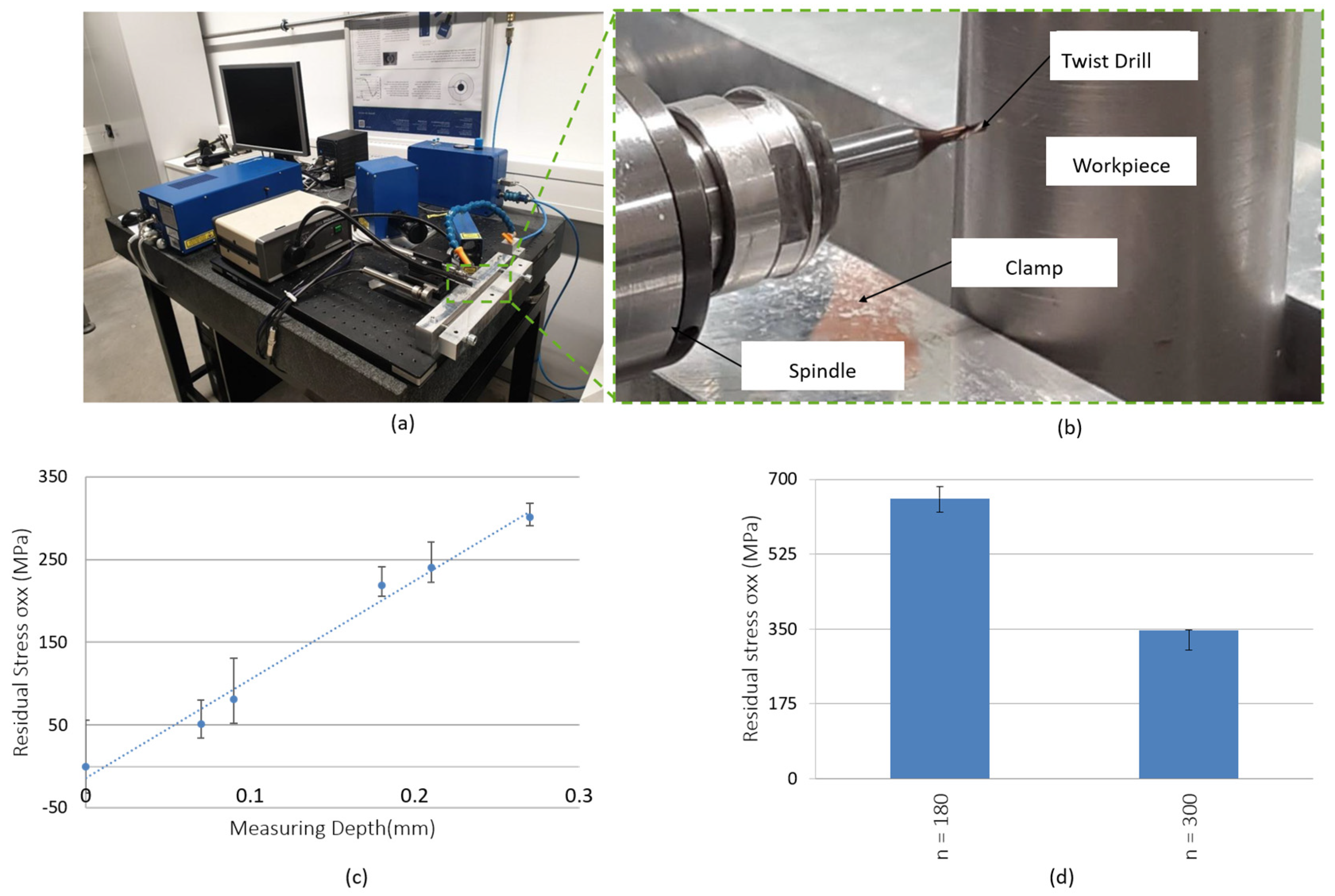
One criterion for evaluating the elastic deformation is the level of residual stress. A higher magnitude of residual stress could result in greater tendency for elastic recovery [
26]. To evaluate the effect of laser structuring on the residual stress, the measurement device and the relevant results for
n = 180 and
n = 300 are shown in
Figure 7.
The results of the residual stress test for the non-structured surface after turning are shown in
Figure 7c, measured after machining.
For n = 180, the residual stress value was also higher compared to n = 300. This indicates a direct correlation between the laser structuring and residual stress. In the hard-turning process, performing laser structuring not only results in tighter dimensional tolerance but also contributes to improved residual stress.
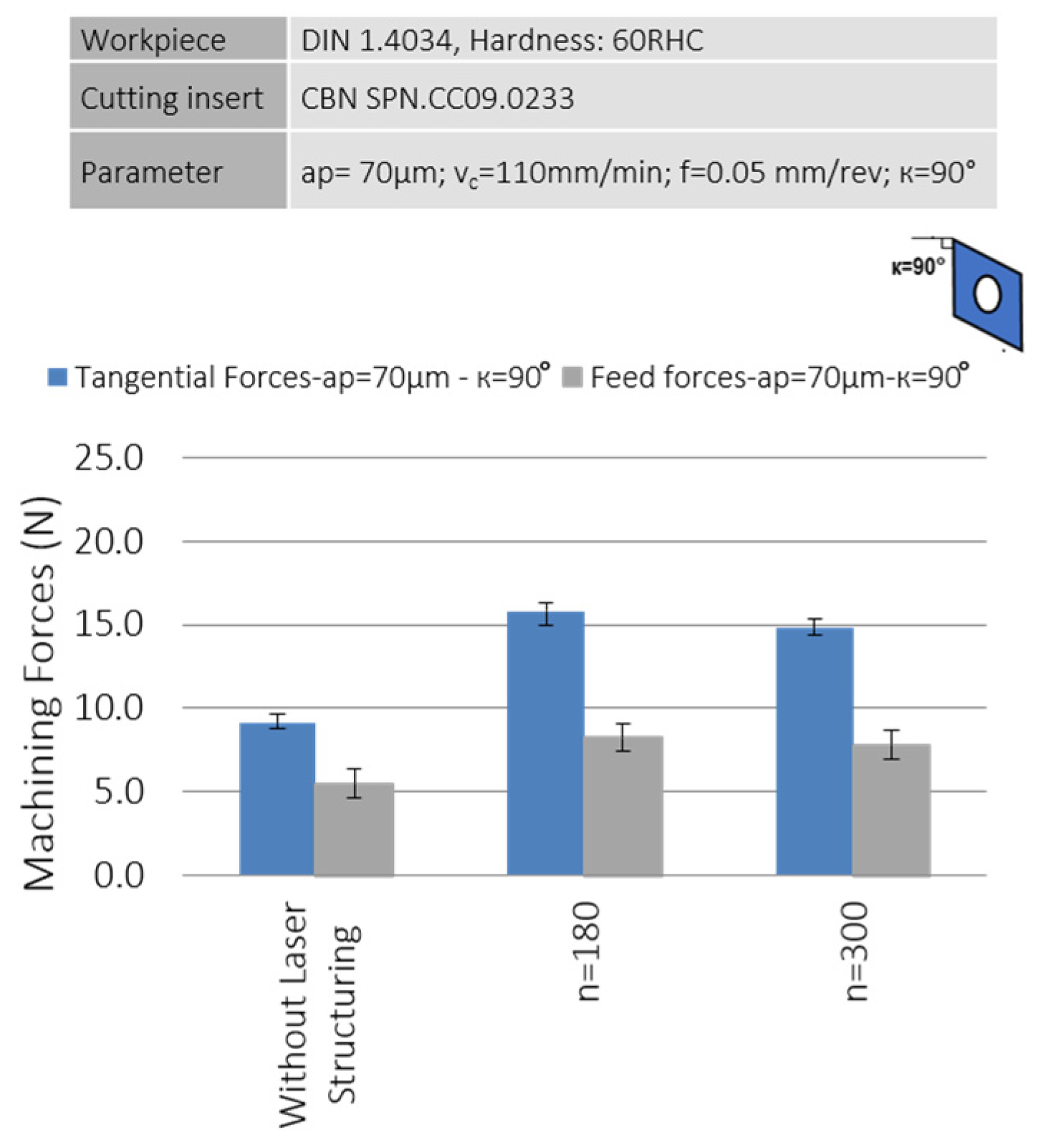
To focus more on surface quality and dimensional accuracy, the cut depth was reduced to 70 µm. This value corresponds to the laser ablation depth, making the evaluation of laser structuring on the machining forces more precise. Therefore, a depth of cut ap = 70 µm was adopted in subsequent tests. Except for the new ap value, the other parameters remained unchanged from the previous parameter settings for the turning process.
Figure 8 presents the machining forces for a
p = 70 µm. For κ = 90°, the forces were increased as the number of laser axial grooves increased. However, the level of the tangential forces was significantly higher.
For n = 300, the feed force was slightly smaller than that of n = 180. This is likely due to the fact that with ap = 70 µm and n = 300, the crack initiation in the cutting zone and, consequently, the chip formation occurred more easily. Based on the results, it can be inferred that laser structuring is particularly effective for small cutting depths.
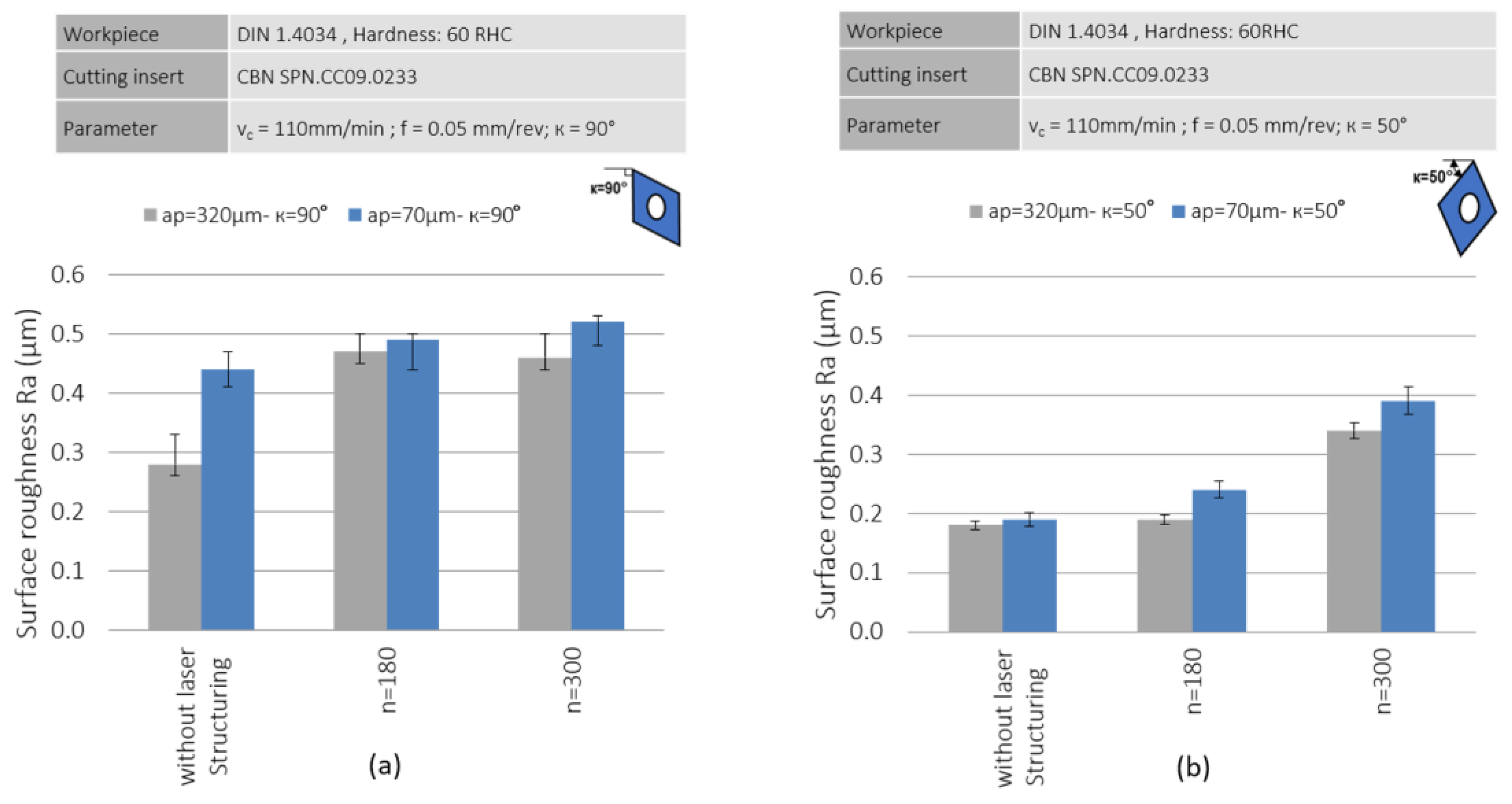
In
Figure 9, the analysis of surface roughness under different approach angles (κ = 90° and κ = 50°) reveals that a smaller approach angle led to better surface quality. At κ = 90°, the laser structuring did not significantly improve roughness, as the structured surfaces (
n = 180,
n = 300) exhibited similar or slightly higher roughness compared to the non-structured surface. Additionally, the influence of a
p = 320 µm and a
p = 70 μm was more pronounced at κ = 50°, suggesting that a lower approach angle enhanced machining efficiency. When the depth of cut (a
p = 70 µm) is much smaller than the tip radius (300 µm), the machining is mainly performed by the tip of the insert. In this case, the rake angle has a highly negative value, leading to plastic deformation and, consequently, a deterioration in the surface quality compared to a
p = 320 µm.
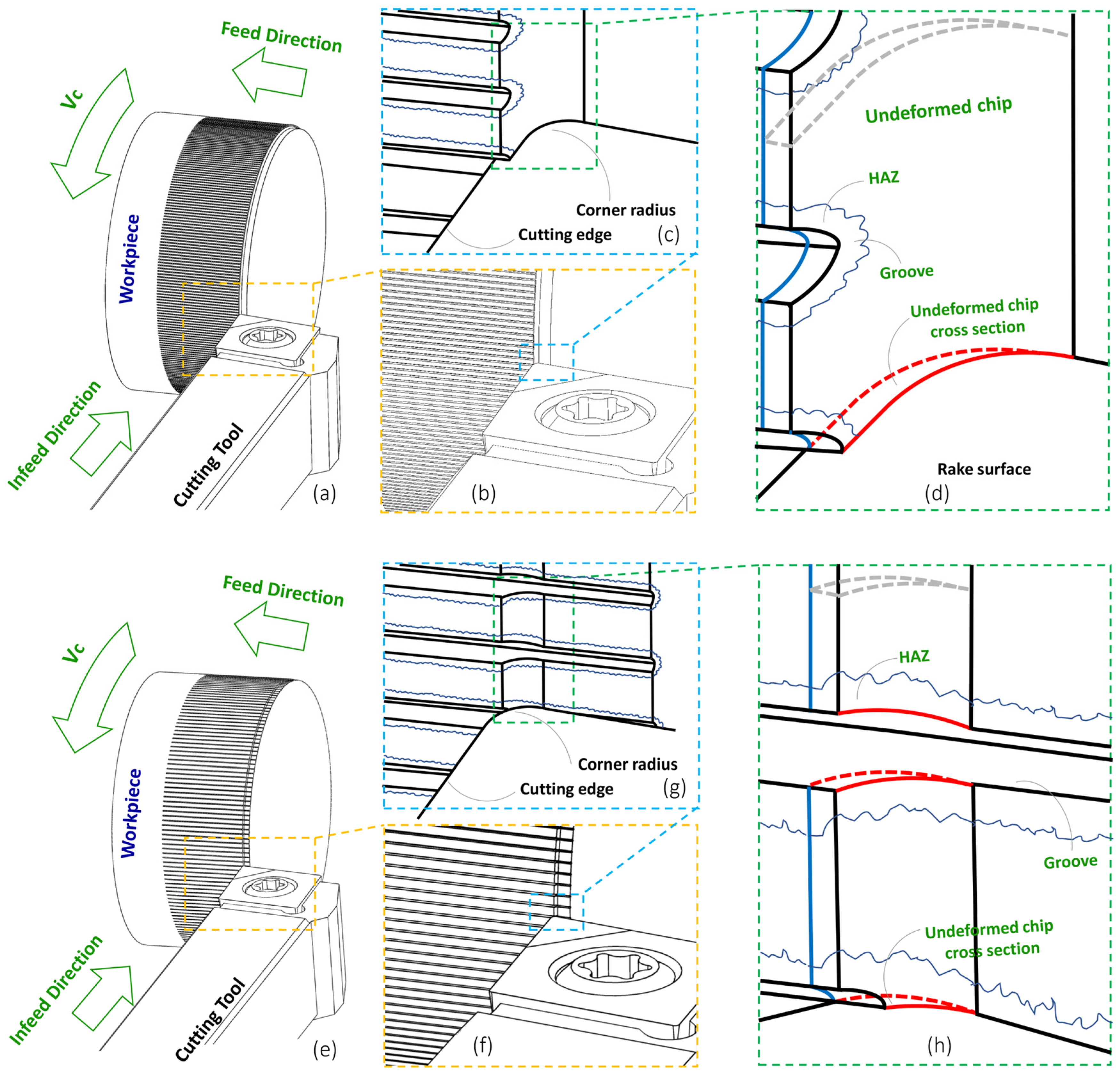
To gain a better understanding of the chip formation,
Figure 10 illustrates schematics related to the undeformed chip for κ = 90° at both a
p = 320 µm and a
p = 70 µm, respectively. According to
Figure 10, at a
p = 320 µm, the cutting depth was several times greater than the depth of the axial laser grooves. Consequently, the chip formation occurred in a less severely interrupted manner. However, this does not imply a mild or continuous chip formation process. In this scenario, as the insert tip passed each laser groove and its relevant heat-affected zone (HAZ), a larger portion of the cutting edge came into contact with the bulk material compared to the case of a
p = 70 µm; therefore, the machining forces were decreased.
Additionally, the absence of material within the laser grooves could influence the breaking of the chip. The reduction in the cross-sectional area of the chip in the laser grooves, along with the brittleness of the surrounding HAZ compared to the bulk material, significantly affected the chip formation process.
In
Figure 10, the cutting depth is approximately near to the depth of the laser grooves. Consequently, two key phenomena could occur. First, chip formation was entirely interrupted. And second, as the insert passed through the mass of the under-cutting material, three distinct contact states were possible: (1) contact with the bulk material, (2) contact with the brittle material (due to being in the heat-affected zone surrounding the laser groove), and (3) passing through the area of the laser groove.
These three contact states occurred simultaneously, leading to two notable outcomes: (1) the chips were sufficiently small, and (2) the rapid transition between contact states prevented the occurrence of the elastic deformation, which was observed in the non-structured samples.
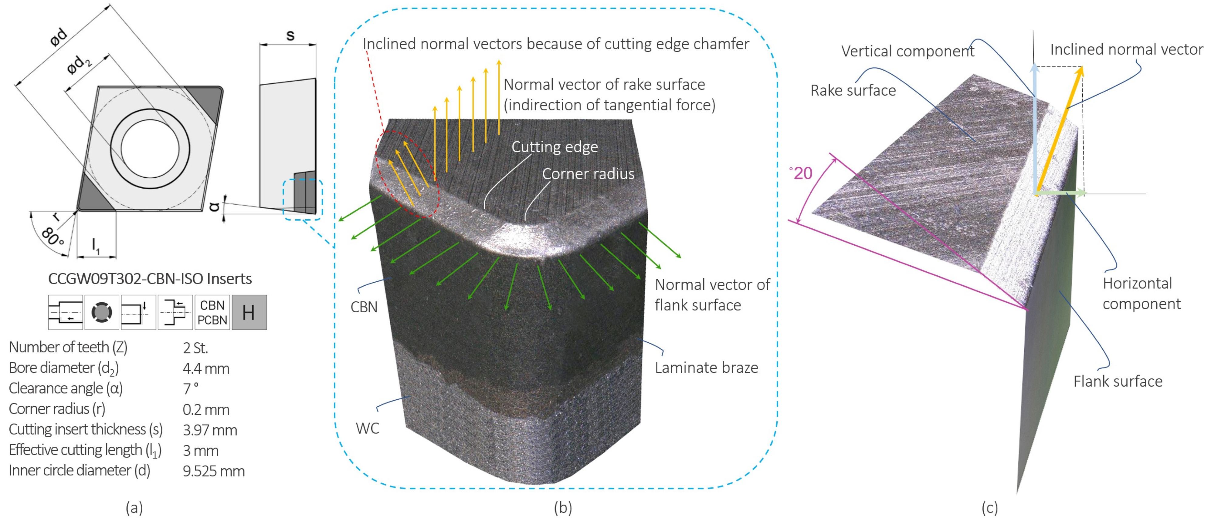
A common aspect for both approach angles was the role of the chamfer on the main cutting edge of the tool and its extension along the radius of the insert tip. This chamfer (
Figure 11), typically ground on the cutting edge, was designed to enhance the durability of the cutting edge and prevent localized dullness, which can happen immediately after that the tool engages with the workpiece material. Depending on the approach angle, a portion of the undeformed chip interacted with this chamfer.
Figure 11c illustrates the normal vectors of the tool’s free surface (green arrows) and chip surface (yellow arrows). In the chamfered region of the cutting edge, the normal chip surface deviated due to the chamfer’s inclination (20°). This affected the distribution of tangential forces, where the vertical component integrates with the main tangential forces of the unchamfered chip surface, while the horizontal component influenced axial and radial machining forces, depending on the tool’s approach angle. As the tool’s approach angle decreased, the length of the chamfered edge increased.
For κ = 90°, a shorter length of the chamfer engaged with the undeformed chip. Conversely, at κ = 50° as
Figure 12 shows, a longer length of the chamfer came into contact with the undeformed chip. If the surface is laser-structured, the chip evacuation is improved.
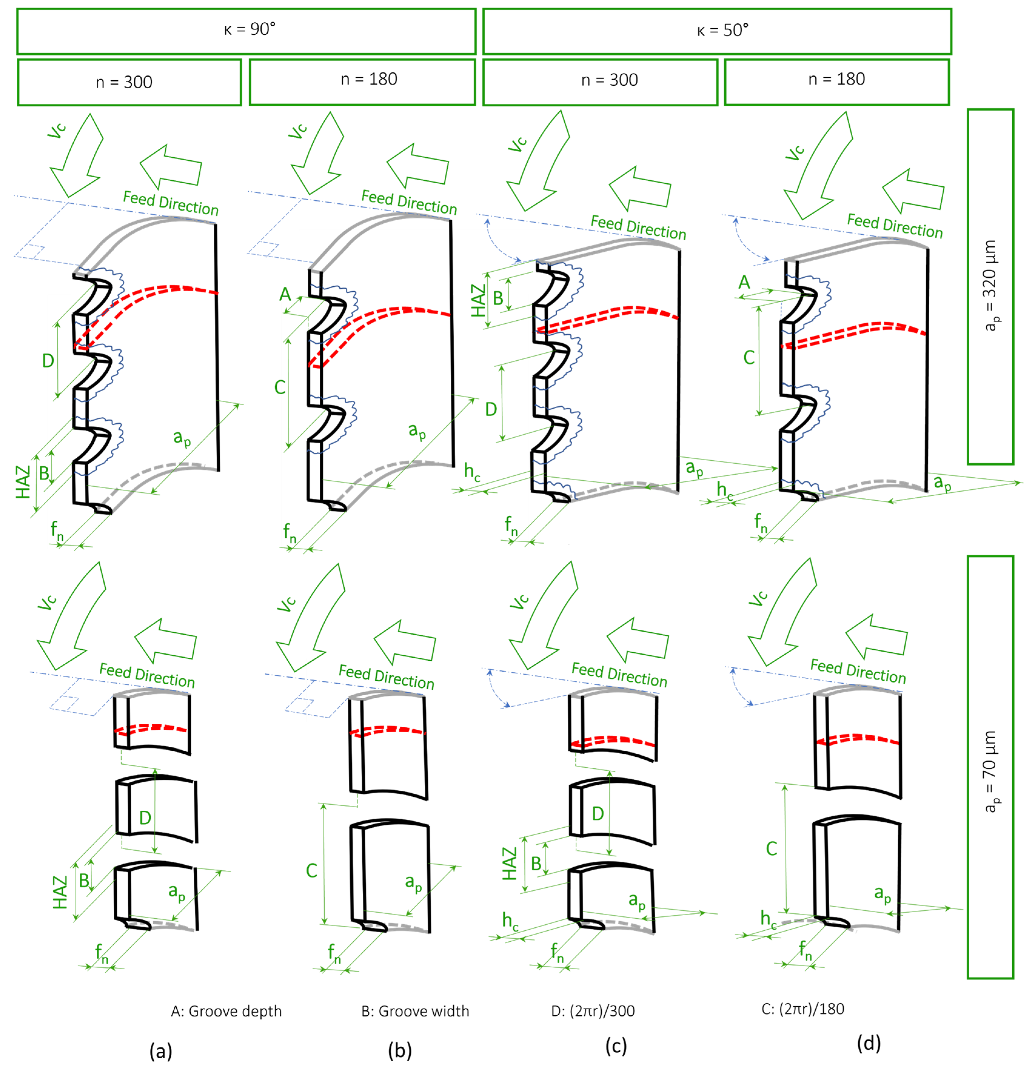
Figure 13 provides three-dimensional schematics of undeformed chips for a
p = 320 µm and a
p = 70 µm, respectively, comparing the approach angles of κ = 90° and κ = 50° with the number of laser grooves of
n = 180 and
n = 300.
Figure 13a,b correspond to orthogonal cutting, while
Figure 13c,d illustrate the distance between two adjacent laser grooves. The primary distinction lies in the chip formation, which becomes fully discontinuous for a
p = 70 µm due to the low cutting depth. In this case, the depth of the laser grooves exceeded the cutting depth.
The distance between the axial grooves is denoted by the value D for the workpiece with 300 axial grooves and by the value C for the workpiece with 180 axial laser grooves. Additionally, the cross-section of the undeformed chip is highlighted with a dashed red line in each case.
As illustrated, the frequency of the interrupted cutting was significantly higher for the workpiece with
n = 300. As the number of laser grooves increased, the distance between adjacent grooves decreased, and the total area of the heat-affected zones (HAZs) expanded. Consequently, the cutting tool was more frequently exposed to contact with the hardened, brittle material, leading to an increase in machining forces, as depicted in
Figure 5.


 ,
, 


