Article

DED Powder Modification for Single-Layer Coatings on High-Strength Steels

by
Unai Garate
1,2,
Enara Mardaras
3,
Jon Arruabarrena
3,
Garikoitz Artola
3,
Aitzol Lamikiz
2 and
Luis Norberto López de Lacalle
2,*
1
MESHIND, Aliendalde 5, 48200 Durango, Spain
2
Aeronautics Advanced Manufacturing Centre, Department of Mechanical Engineering, University of the Basque Country, 48013 Bilbao, Spain
3
AZTERLAN, Basque Research and Technology Alliance (BRTA), 48200 Durango, Spain
*
Author to whom correspondence should be addressed.
J. Manuf. Mater. Process. 2025, 9(5), 152; https://doi.org/10.3390/jmmp9050152
Submission received: 9 April 2025 / Revised: 29 April 2025 / Accepted: 3 May 2025 / Published: 6 May 2025
(This article belongs to the Special Issue Advances in Directed Energy Deposition Additive Manufacturing)

Abstract

:
In the design of L-DED (laser-directed energy deposition) cladding processes, the chemical composition of the metallic powders is typically assumed to match that of the intended coating. However, during the deposition of the first layer, dilution with the substrate alters the weld metal composition, deviating from the nominal powder chemistry. Although the application of multiple layers can gradually reduce this dilution effect, it introduces additional complexity and processing time. This study proposes an alternative strategy to counteract substrate dilution from the very first deposited layer, eliminating the need for multilayer coatings. Specifically, to achieve a corrosion-resistant monolayer of AISI 316L stainless steel on a high-strength, quenched-and-tempered AISI 4140 steel substrate, a dilution-compensating alloy powder is added to the standard AISI 316L feedstock. Single-layer coatings, both with and without compensation, were evaluated in terms of chemical composition, microstructure, and corrosion resistance. The results show that unmodified coatings suffered a chromium depletion of approximately 2 wt.%, leading to a reduced pitting potential of Ep = 725 ± 6 mV in synthetic seawater. In contrast, the use of the compensation alloy preserved chromium content and significantly improved corrosion resistance, achieving a pitting potential of Ep = 890 ± 9 mV.

1. Introduction

The use of weld overlays for corrosion protection of high-strength steels is widespread in the manufacture of boilers and pressure vessels. This has led over the years to the development of standardized procedures that describe what the requirements and qualification procedures for the overlay weld metal are [1]. One of the main concerns regarding the weld metal is the dilution that happens between the steel substrate and the corrosion resistant alloy employed for the cladding overlay, both in the engineering codes [2] and in industrial practice [3]. Despite dilution being described qualitatively in the codes as “low”, “considerable”, or “high” [2], it can be found quantified in the literature as the ratio between the contribution of the base metal volume substrate and total weld metal volume in the coating (Figure 1) [4] or the depth of the weld track into the substrate. Since the latter was found to show a weaker correlation to the chemical composition of the weld metal [5], the former is used in this work.
Dilution reaches its maximum in the first coating layer and adding more overlays on top of it reduces the dilution in each successive layer in approximately a geometric progression. This raises concern in industrial practice, as the qualification of the Welding Procedure Specification (WPS) of any weld metal overlay is required to nominally match the chemical analysis requirements of the equivalent base metal [1]. The more different the base metal composition is from the target coating composition, the higher the influence of dilution in the deviation of the weld metal composition from its aimed specification.
This is influenced by the WPS parameters, and some cladding techniques allow lower dilution than others. A study by Gittos et al. [6] showed that when aiming to clad Inconel 625 on AISI 1015 carbon steel, employing manual metal arc (MMA) welding and high dilution, and metal inert gas (MIG) and hot wire tungsten inert gas (HWTIG) welding, should take four layers to yield the desired Cr content in the weld metal. On the contrary, electroslag welding is known to have the ability to allow single cladding layers in some cases thanks to its low dilution [2]. To compensate for dilution, specific filler wires are available for a reduced number of applications that are deployed via arc welding (MMA, MIG, HWTIG). The case referred to in the welding codes is the use of AISI 309-series stainless steel with Mo addition filler wire, commonly identified as ER309Mo, on carbon steel substrates to achieve a single layer of AISI 316L weld metal.
In addition to conventional cladding techniques, additive manufacturing-based processes are gaining research interest for corrosion protection coating. L-DED cladding is of special interest in terms of adjusting dilution capabilities [7]. This ability has even attracted research into corrosion protection with L-DED for highly alloyed coatings and alloy families, which are required to maintain a narrow tolerance in chemical composition [8]. When a low coating thickness is allowed and the provided equipment kinematics are capable, high-speed (HS) L-DED is an alternative for this type of situation where the acceptable level of dilution is low [9]. This leads to better corrosion protection than conventional L-DED when the same filler is used [10]. Nevertheless, HS L-DED is not always effective in containing the contribution of the substrate to the first layer of weld metal. HS L-DED yields dilution rates that can go from as low as 3%vol. [11] to as high as 50%vol. [12] for coatings that are 300 microns thick. This makes it difficult to achieve monolayer L-DED corrosion barriers on low-to-medium alloy steels, especially when coating with alloys with an admissible low Fe content.
A clear example is the use of Inconel 625 as filler material, whose specified iron content is 5 wt.% Fe maximum. Both the works from Gittos et al. [6] and Gui et al. [13] explored coating low-alloy steels with Inconel 625. The former employed arc welding while the latter employed L-DED and HS L-DED. Gittos’ results indicated dilution percentages exceeding 20%vol., while dilution for L-DED was reported to be around 15%vol. for L-DED and below 5%vol. for HS L-DED by Gui. It is noteworthy that the coating thickness was up to 2 mm for the L-DED coating and below 0.8 mm for the HS L-DED. Only HS L-DED would meet the criteria of having less than 5 wt.% Fe as specified in the standards. These results highlight that not all corrosion-resistant cladding options can be manufactured as single-layer coatings onto low and medium alloy steels. HS L-DED could be an alternative, but it is affected by some limitations in geometry and thickness.
Stainless steel coatings are not as affected by the Fe wt.% limitation of Ni-based alloys such as Inconel 625 and have been shown to lead to good results with HS L-DED. Chen et al. combined 27SiMn with AISI 304L and found corrosion potential values on a 3.5 wt.% NaCl solution at −0.384 mV to be comparable to wrought AISI 304L [14]. Shifting to L-DED though in similar material combinations has been proven to affect corrosion performance of stainless steel compared to wrought. As observed by Garate et. al. with AISI 316L single layers on an AISI 4140 substrate [15], dilution caused the Cr content in the weld metal to drop from 17 wt.% to 15 wt.% A decrease of 400 mV in the pitting corrosion resistance was observed in this case by polarization testing in physiological media at 36 °C (measured with a Ag/AgCl electrode), which was attributable to the Cr content reduction. This reduction of Cr to around 15 wt.% has also been observed by other authors working in welding technologies that avoid the use of a filler material, such as friction stir welding, and should be beneficial in terms of minimizing dilution [16].
An approach to avoiding Cr content reduction and retaining the filler powder’s corrosion resistance in L-DED corrosion resistant single-layer coatings would be using a filler powder version of the ER309M wire. Nevertheless, insights from Mamphekgo et al. [17] and Bozeman et al. [18], who used wire-based L-DED coatings with AISI 309L, suggest that the welding parameters that are used in L-DED may require an alternative solution. The former reported that welding multi-pass layers of AISI 309 onto a similar material such as AISI 304L could yield differences of 2 wt.% Cr in the weld metal, depending on the process parameters. This means that even in the most favorable conditions, the weld metal can show variations in Cr content as wide as the specification range of the powder. The latter showed that the Cr drop was worse when coating AISI 309L onto 1018 carbon steel. The worst condition coatings reduced Cr wt.% and Ni wt.% below AISI 316L’s specification, with dilutions close to 30%vol. not being uncommon in L-DED single-layer coatings thicker than 1 mm.
Compared to wire-based L-DED, powder-based L-DED offers the possibility of compounding the filler metal by mixing two or more different powders in the melt pool. This allows compounding a principal filler powder, whose composition is the desired one in the coating, and another powder that can compensate for the loss of alloying generated by dilution. Despite powder compounding for coatings involving stainless steel being found in literature for wear resistance improvement [19,20], its use for corrosion resistance improvement still shows a broad scope for further research. This work is a contribution to this last field of knowledge and proposes a methodology for designing and employing compensating power to be compounded with stainless steels for powder-based L-DED monolayer coatings of stainless steels onto low- and medium-alloy steels. The work is focused on representative alloys for the steel families AISI 316L and AISI 4140 to show the potential achievable corrosion improvements. Furthermore, it is aimed to prove that it is feasible to perform the compensation with a reduced percentage of ad hoc powder in the mix, so that the economy scale advantage of employing AISI 316L powders is not completely lost by using a single ad hoc powder instead of compounding.

2. Materials and Methods

2.1. Determination of the Compensation Powder Composition

A 1 mm thick single-layer coating was applied by L-DED (Trumpf 3000 compact LC machine, Ditzingen, Germany) using AISI 316L powder as the cladding material and AISI 4140 steel plate as the substrate to obtain a specimen that served as a reference. This specimen, which is referred to in the text as reference specimen, was used to determine the dilution of the substrate under the applied cladding parameters, and calculate the composition of the compensation powder (CP).
The chemical compositions of both the AISI 316L powder and the AISI 4140 plate are shown in Table 1. A large plate (300 × 100 × 20 mm) was chosen to maximize the heat dissipation during the L-DED process and emulate the behavior of the coating process in an industrial part. The AISI 316L powder was commercial grade with a Si content higher than that established under the AISI 316L designation, which gives the material a greater deoxidizing capacity for its use in welding processes. Following the recommendation for the L-DED process, a powder with a particle size distribution in the range 45–106 µm was selected. The chemical compositions shown in Table 1 were determined by coupling ICP-OES (inductively Coupled Plasma Optical Emission spectroscopy) measurements on a Thermo Fisher Scientific iCAP 7400 ICP-OES spectrometer (Thermo Fisher, Waltham, MA, USA) and combustion analysis on an LECO ON736 infrared automatic analyzer (LECO, St. Joseph, MI, USA).
A process of adjusting the cladding conditions was carried out to achieve the optimal parameterization (Table 2). The reference specimen was manufactured using these optimized parameters. Due to the low thickness of the coating, the chemical composition of the reference specimen in Table 1 was determined by X-ray fluorescence analysis using a Thermo Fischer Scientific NITON XL2 XRF analyzer (Thermo Fisher, Waltham, MA, USA). X-ray fluorescence is a low-penetration analysis technique, so interference with the substrate is avoided in the determination of the coating’s chemical composition. The analysis surface was ground to ensure that the surface oxidation of the coating did not interfere with the analysis results and the results are representative.
Based on the chemical compositions from Table 1, the dilution coefficients corresponding to each element (R[%X]) were calculated by means of Equation (1):
R [ % X ] = % X R e f e r e n c e   S p e c i m e n [ % X A I S I   4140 ] % X A I S I   316 L % X R e f e r e n c e   S p e c i m e n
with %XReference Specimen being the wt.% of element X in the reference specimen; %XAISI 4140 the wt.% of element X in the AISI 4140 substrate; and %XAISI 316L the wt.% of element X in the AISI 316L powder.
The proportion of the CP in the compensated filler compound (CFC) was chosen for this study to be 10% (Z = 10%). Despite the choice of the value for Z being arbitrary, a balance was sought between using a low Z, taking advantage of the economy of scale of using commercial AISI 316L powders, while keeping proper compounding behavior (mixability in powder format and in the melt pool). Using the dilution coefficients determined above and applying Equation (2), the content in wt.% of each element in the CP (XCP) was determined.
% X CP = R % X + 1 · % X R e f e r e n c e   S p e c i m e n 1 Z 100 · R % X · % X A I S I   316 L [ % X A I S I   4140 ] Z 100 · R [ % X ]
The resulting dilution coefficients and the CP powder’s nominal chemical composition are shown in Table 3.

2.2. Methodology for the Manufacturing of the Compensated Filler Compound

The manufacturing process followed for the manufacturing of the CP is shown in Figure 2. Once the composition of the CP was determined, a batch of 100 kg was prepared by providing different proportions of commercial ferroalloys till the desired composition was obtained. The batch was melted in an induction furnace at 1650–1700 °C and poured into several ingot molds. The ingots were machined to obtain bars with a diameter of 8 mm and length of 100 mm, so that they could be processed in the atomization unit (3DLabs ATOLab ultrasonic atomizer). After preliminary testing under different atomization conditions, the optimal atomization parameters were those listed in Table 4. A key variable for the atomization process is the material the atomization platform is made of. For this study, steel and tungsten platforms were tested, the latter being the one that exhibited the best performance in terms of atomization rate. The resulting CP was sieved to 15–100 µm for its use in the CFC for the L-DED process and it was immediately placed in a closed container to avoid oxidation till its final use.
The CFC was obtained by mixing the AISI 316L with the CP in a 1:9 proportion. For an effective homogenization, the mixture of both powders was mixed using a tumbler) and immediately stored to prevent the finer powder particles from settling down at the bottom. The CFC was used to manufacture the compensated specimen using the same cladding parameters employed for the reference specimen, as shown in Table 3.

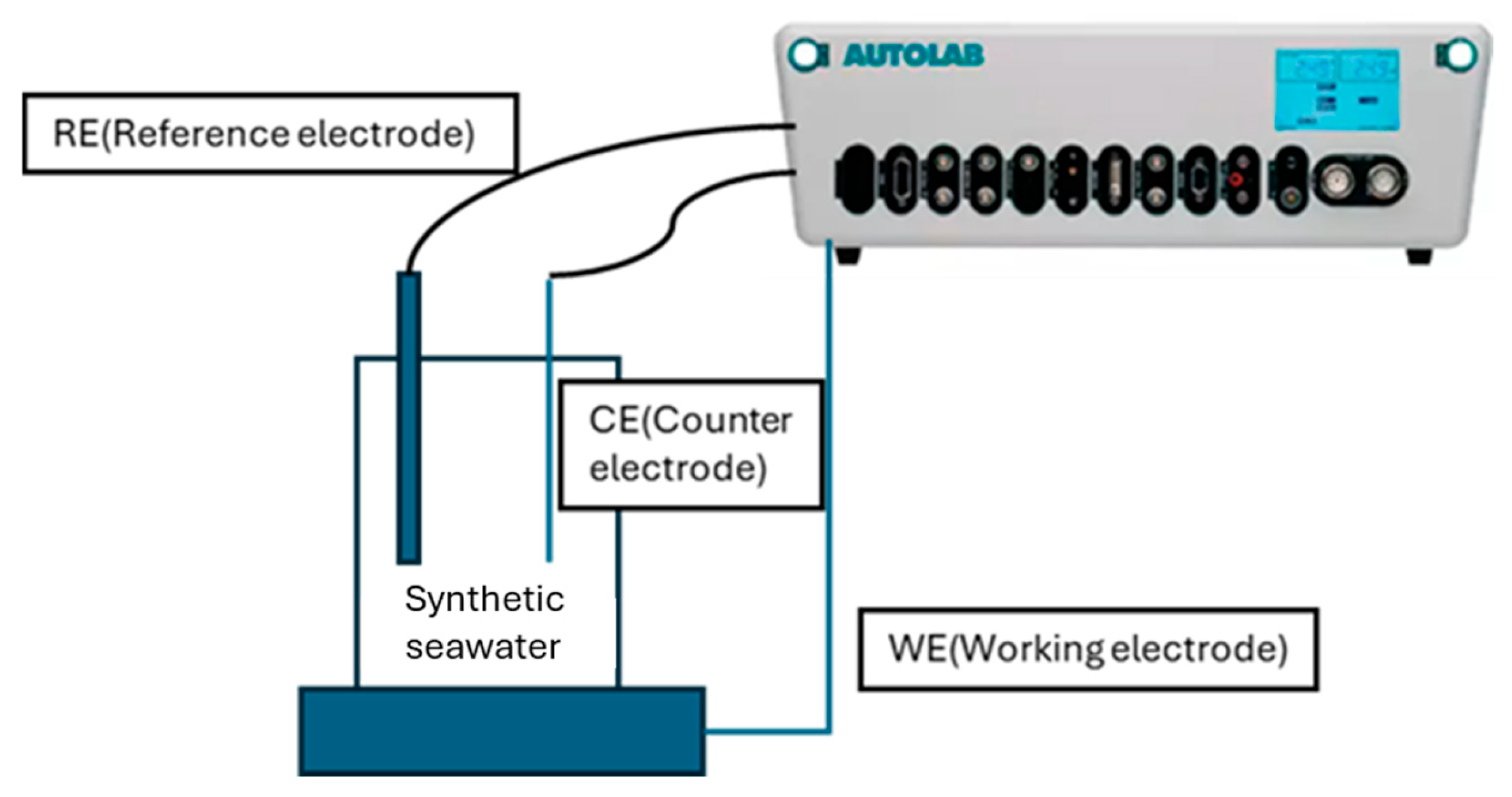
2.3. Corrosion Testing

Electrochemical measurements were performed on L-DED-coated specimens as the working electrode (WE). They were assembled with polymethyl methacrylate (PMMA) tubes of 24 mm in diameter and 180 mm in height to form a conventional three-electrode cell, as detailed in Figure 3. The reference electrode (RE) was a saturated Ag/AgCl electrode, and the counter electrode (CE) was a platinum wire.
Electrochemical measurements were conducted at room temperature under static flow conditions using an Autolab PGSTAT 302N model potentiostat/galvanostat (Metrohm, Herisau, Switzerland). The corrosive medium consisted of substitute ocean water (synthetic seawater) in accordance with the standard ASTM D1141-98 [21]. The composition of the synthetic seawater is shown in Table 5. In all cases, the contact area was approximately 1.20 cm2. The samples were ground with 1200-grit paper. After that, they were polished with diamond suspension, cleaned with alcohol, rinsed with distilled water, and dried with propelled air. Before the electrochemical testing, the samples were allowed to stabilize at their open-circuit potential (Eocp) for 90 min. The potentiodynamic polarization measurements started from −250 mV cathodically with respect to the open-circuit potential, at a constant scan rate of 0.167 mV/s, to a potential of +250 mV anodically. The corrosion current density values were obtained by using the Tafel extrapolation method.

3. Results

3.1. Chemical Composition of the L-DED Coatings With and Without Dilution Compensation

One of the objectives of this study is to verify that the L-DED single-layer deposition using the CFC produces a coating whose chemical composition falls within the range defined by the AISI 316L grade standard. To achieve this, the chemical composition of the coating was determined in the same way as with the reference specimen. Table 6 shows the composition range defined under the AISI 316L designation and the chemical composition determined in the coating of the compensated specimen. To facilitate the comparison between using compensated or non-compensated filler material, the composition determined in the coating of the reference specimen is also included.
As a result of dilution, the coating obtained through the non-compensated deposition of AISI 316L (reference specimen) has a chemical composition that deviates significantly from the standard composition range. The most concerning aspect is the contents of Cr and Ni, which are well below the specified range, as the corrosion-resistant property of the coating relies on the content of these two elements.
In turn, the composition of the coating in the compensated specimen falls within the range of the AISI 316L standard, proving the effectiveness of the CP addition, except for two elements, C and Si, the contents of which are above the specified range.
In order to achieve a better comprehension of the fusion process of the powders in the melt pool, a study was conducted using the Thermo-Calc software (Thermo-Calc 2024b/TCFE9 database). The solidus and liquidus temperatures and phase transition latent heat of the AISI 316L cladding material, AISI 4140 substrate, CP, and CFC were determined. For such calculations, the Scheil–Gulliver model was used assuming that there is no back diffusion from liquid into solid, which seems accurate enough for the purpose, given the rapid solidification conditions on L-DED. The results are summarized in Table 7.

3.2. Microstructure Analysis

The cross-section of the coating was prepared metallographically for the corresponding microstructural analysis using an SEM. The microstructure was revealed by electrochemical etching in oxalic acid for 90 s and 1 A/cm2 [22]. Representative micrographs of the microstructures developed on the coatings of the reference specimen and compensated specimen are presented in Figure 4. As expected, both coating layers exhibit the cellular structure characteristic of rapid solidification processes, such as those taking place in PBF or L-DED [23]. The microstructure consists of γ-phase cells and eutectic networks at cell boundaries as pointed out by the green arrow in the zoomed-in image of the region of interest marked by the red box in Figure 4a.
No significant differences are observed between the microstructures in the coating layers: the cell size ranges from 5 to 6 µm, and no appreciable differences are found in the cellular structure. The use of CFC does not significantly affect the consolidation of the bond between the substrate and the coating, nor is it observed to lead to a higher density of gas entrapments (porosity) in the coating compared to the coating in the reference specimen. The hardness of the coating in the compensated specimen is slightly lower than that of the hardness in the reference specimen, 198 HV and 203 HV, respectively.
The microanalyses conducted by EDS showed a notable difference in the chemical composition determined in the cell interior and at the cell boundaries, especially concerning the Cr and Mo contents. As indicated in Table 8, Cr and Mo exhibit a strong positive segregation towards the liquid during solidification, which causes the enrichment of the cell boundaries with these two elements. Ni shows the same trend, although the segregation is much weaker.

3.3. Potentiodinamic Polarization Test

Electrochemical tests, including on the OCP and potentiodynamic polarizations, were carried out on the reference specimen and compensated specimen to investigate the influence of dilution compensation on the corrosion performance. Synthetic seawater, whose composition is shown in Table 5, was used as the electrolyte.

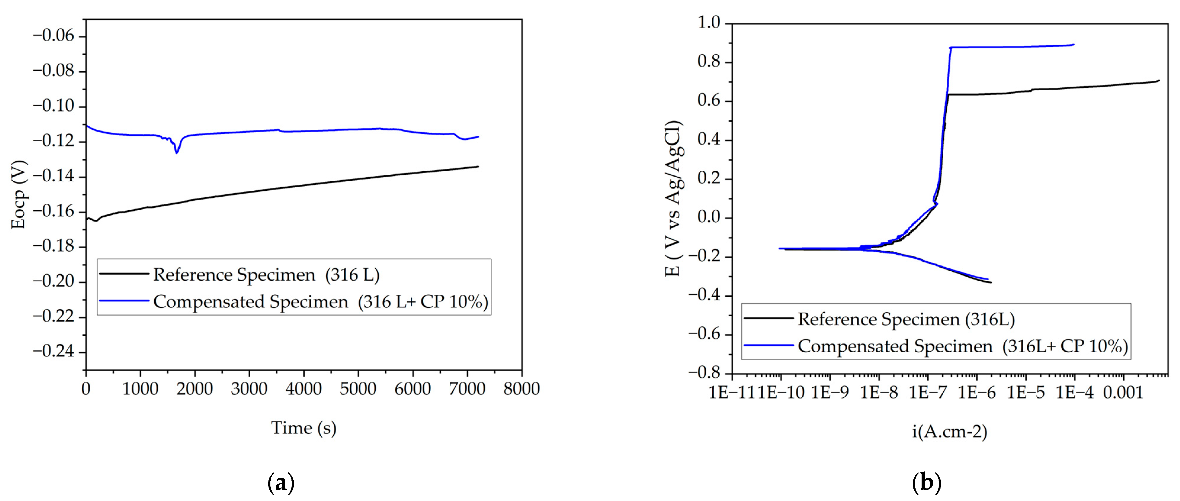
3.3.1. Open-Circuit Potential

The variation in OCP was used as an indicator to evaluate the formation, dissolution, and stability of a passive layer. Three repeats were performed to ensure repeatability. The plots of OCP for the reference specimen and the compensated specimen (316L + CP 10%) are shown in Figure 5a. In the reference specimen, a positive shift in potential that indicates the formation of a passive layer is observed, which implies a reduction in corrosion tendency (an improvement in corrosion resistance). On the other hand, the compensated specimen shows a steady potential, that means the passive layer remains intact and protective [15].

3.3.2. Potentiodynamic Polarization

Figure 5b illustrates the polarization curves for the reference specimen and compensated specimen (316L + CP 10%) claddings. As shown in Figure 5b, both curves display passive behavior, with breakdown caused by pitting corrosion.
The compensated specimen (316L + CP 10%) exhibits an extended passive behavior, without any evident metastable pitting and with the highest pitting potential (Ep) at 890 mV versus Ag/AgCl (3 M KCl) in a neutral solution (see Table 9 and Figure 5b). This remarkable improvement in Ep is related to the use of the CFC.

4. Discussion

The use of a CFC serves to adjust the composition of the coating with the composition interval defined for AISI 316L for either the Cr or Ni content (Table 5). Nevertheless, the content of C and Si are higher. Reducing the C content of the coating is not a matter that can be addressed from the cladding material compensation perspective, and instead other measures must be corrected. One possibility to counteract this carbon input from the substrate lies in the use of decarburizing gases, such as oxygen, in combination with the shielding gas to promote the oxidation of C and its removal as CO2. Such a study is beyond the scope of this project, but it opens an interesting field that calls for research to reduce the carbon content when applying stainless-steel coatings onto carbon steels. The Si content being above what is established by the standard is due to the AISI 316L powder used, as it is a AISI 316L alloy with a Si content of 2.3 wt.%, specifically added to improve the deoxidation of the molten pool during the welding process. As seen later, this Si content in the coating of compensated specimen has no adverse effect on either the microstructure or the corrosion resistance properties of the coating.
The CP exhibits a relatively wide melting temperature range; however, the liquidus temperature is significantly lower than that of the AISI 316L (Table 6). According to this, the CP would melt first and would homogenize instantly in the melt pool. In Figure 6, the evolution of the liquid fraction with temperature is compared for the powder and substrate. The CFC exhibits a melting temperature lower than that of the AISI 316L, but this is a simplification, since when the composition of the CFC is introduced for the calculation, the result corresponds to an alloy that meets that chemical composition, when in reality, this is not the case, since the material mixture of the two powders (AISI 316L and CP) is in a 1:9 ratio. At temperatures higher than 1150 °C, the liquid fraction in the CP is greater than 50%, so there would be liquid wetting the AISI 316L particles, meaning the melting temperature of the CFC could be occurring in practice at temperatures significantly lower than those indicated by the calculation.
Nevertheless, it must be taken into consideration that the CP exhibits a significantly higher latent heat; that is, it requires a higher amount of energy to experience the solid-to-liquid phase transition. Such an effect could result in a dissimilar melting progress to the melt pool, internal stresses, and finally impact on the quality of the coating and its homogeneity, especially if both materials are not perfectly mixed when feeding. In this study, no signs of such issues were observed. In this sense, it is important to indicate that the compensated clad material (mixture of AISI 316L and CP) was mixed in a tumbler prior to being fed into a single powder feeder for L-DED, which ensured its effective homogeneity.
It is also relevant to point out that the melting temperature range of the compensated clad material was significantly lower than that of the AISI 4140 substrate. Such a fact implies that the substrate material integrated gradually into an already well-homogenized melt pool as the cladding operation proceeded.
The incorporation of CP into the AISI 316L did not have a significant impact on the solidification range, and the latent heat increased slightly with respect to that of AISI 316L; so, the same parametrization used for the reference specimen manufacturing could be employed for the compensated specimen. The solidification microstructure of the coating layer was identical to the one obtained without compensation, as evidenced by the SEM micrographs in Figure 4. The proper melting and deposition of the CFC was verified through the microstructural analysis of the compensated specimen. No unmelted particles were found in the cladding layer. Given the ultrarapid solidification conditions in L-DED, a cell structure is formed as the coating layer solidifies. This structure is homogeneous in almost the entire coating, except for the areas near the substrate, where the cells acquire an elongated shape rather than the hexagonal shape observed in Figure 4. The average cell size ranges between 5 and 6 µm.
The EDS measurements performed at different positions of the cell interiors and cell boundaries showed that despite the solidification taking place in an extremely short time interval, there was time for alloy enrichment in the liquid phase. According to the results from Table 7, the difference in composition between cells and cell boundaries is more pronounced in the reference specimen than in the compensated specimen. In the reference specimen the Cr content at the cell boundaries is 18% higher than that within the cell. In contrast, this difference is just 9% in the case of the compensated specimen. Regarding the Mo content, a similar trend is observed. The Mo content at the cell boundaries in the reference specimen is 59% higher than in the cell interiors, whilst in the compensated specimen the difference is 53%. In contrast, the difference in Ni content between cell interiors and boundaries is significantly lower, 4.5 wt.% and 6.8 wt.%, for the reference specimen and compensated specimen, respectively.
The element segregation to the cell boundaries is governed by the partition coefficient of the elements, their influence on phase stability, and their diffusion characteristics. Experimental measurements conducted onto the Fe-Ni-Cr system reported partition coefficients in the range 0.98–1.15 for Cr in delta ferrite and around 0.85 for Ni [24]. This implies that during delta ferrite formation the liquid is enriched in Ni, but is not enriched as much in Cr. In contrast, in austenite, partition coefficients of 0.96 and 0.98 are reported in stainless austenitic steels for Cr and Ni, respectively, and around 0.7 for Mo [25]. To verify if the solidification mode, austenitic (A), austenoferritic (AF), or ferroaustenitic (FA) could be the reason behind the segregation differences observed between the reference specimen and the compensated specimen, the solidification process was analyzed using empirical equations, related diagrams, and a thermodynamic simulation. The Creq/Nieq ratios, determined according to the equations proposed by Schaeffler [26], yield ratios of 1.49 and 1.38, for the reference specimen and compensated specimen, which implies solidification modes of AF and FA, respectively. However, the calculations performed using the Scheil module of Thermo-Calc suggest that in both cases the solidification mode would be FA, meaning that delta ferrite forms initially, followed by austenite as solidification progresses.
In Figure 7, the concentration profiles of the elements Cr, Ni, and Mo are shown across the radius of a 5-micron-size solidification cell, determined using the diffusion module of Thermo-Calc for both the composition of the coating in the reference specimen and the compensated specimen. The continuous line corresponds to the situation at the end of solidification when considering rapid cooling conditions (classic Scheil), and the dashed line represents the situation where subsequent cooling to 1000 °C is conducted within 5 s. The vertical line in Figure 7a illustrates the hypothetical position of the transition between delta ferrite and austenite, which, as can be seen, causes a step in the concentration profiles of the elements as a result of the change in the partition coefficient associated with each phase. As seen, as expected, all the elements show a net positive segregation towards cell boundaries, and the segregation tends to reduce significantly after cooling to 1000 °C.
Considering the results from Table 7 and assuming that the composition determined inside the cell corresponds to the composition of the solid, and the composition at the cell boundary corresponds to the final composition of the liquid phase, the partition coefficients for Cr, Mo, and Ni (KCr, KMo, and KNi) were estimated. On the other hand, the partition coefficients were also determined based on the results shown in Figure 7 and the composition of the residual liquid after solidification. The values are compared in Table 10. The decrease in Cr segregation in the compensated specimen, as determined experimentally, is also corroborated by the simulation results, as an increase in the partition coefficient in austenite (KCr) is determined in the case of the compensated specimen. In the case of Mo, the experimental results do not indicate a significant change when comparing the reference specimen and the compensated specimen. Similarly, the simulation results do not appear to suggest any variation. As for Ni, the simulation does not suggest a significant change in the partition coefficient between the composition of the coating layer of the reference specimen and the compensated specimen. However, the experimental results indicate a slight change, which translates into a more pronounced segregation of Ni towards the cell boundaries.
To investigate the effect of the compensation powder on the corrosion resistance of AISI 316L coatings in synthetic seawater, potentiodynamic polarization curves and the corresponding electrochemical parameters of the reference specimen and the compensated specimen were obtained, as shown in Figure 5 and Table 8. According to electrochemical theory, materials with higher corrosion potential and smaller corrosion currents exhibit better corrosion resistance. Otherwise, corrosion resistance is worse. According to the literature, the discrepancy value (<40 mV) of Ecorr is insufficient to distinguish the difference between the electrochemical behavior of the L–DED-coated specimens [27]. The obtained Icorr values were similar too. At this point, the Ep value becomes the main criterion for comparison. The reference specimen exhibited the lowest Ep values, indicating the poorest pitting corrosion resistance.
The improvement in the pitting resistance of the compensated specimen is related to the chemical composition of the cladding layer. As shown in Table 5, between two specimens there was a difference of 1.8 wt.% of Cr. The difference in the chemical composition was caused by the CP. The increase in Cr concentration is conducive to enhancement of the corrosion resistance of the coating [28]. Furthermore, the EDS analysis conducted on the L-DED coated specimens distinguished higher differences in the Cr, Mo, and Ni element contents between cells and cell boundaries in the reference specimen than in the compensated specimen (Table 6). Such elemental segregation at cell boundaries is expected to influence the corrosion characteristics [29].
Lodhi et al. [30] investigated the pitting behavior of additive-manufactured AISI 316L in artificial seawater, discovering that pitting appeared to occur at the (Cr, Mn, Al, Si)-0 inclusions of the specimen surface after cyclic polarization tests. Hong et al. [31] researched the precipitates of Cr-rich AISI 316L, showing that they usually appeared along the grain boundary. Liu et al. [32] demonstrated that the Cr-depleted zone around the precipitates provides a favorable position for the breakdown of the passivation film, in this way affecting the stability of the passivation film and reducing the corrosion performance.

5. Conclusions

The results of this study lead to the following conclusions regarding the use of compensation powder (CP) mixed with commercial AISI 316L powder in the L-DED process:
  • L-DED demonstrates strong potential for fabricating multifunctional surfaces by allowing flexible manipulation of feedstock compositions, enabling the rapid production of tailored cladding layers.
  • The addition of compensation powder to AISI 316L results in a laser-clad layer that closely matches the theoretical composition of standard AISI 316L stainless steel.
  • A more homogeneous distribution of alloying elements, particularly C and Cr, within the matrix effectively delays the initiation of galvanic corrosion and pitting phenomena.
  • Potentiodynamic polarization tests indicate that the pitting corrosion resistance of the deposited layer improves with increased elemental homogeneity, especially in terms of C and Cr dispersion.

Author Contributions

Conceptualization, G.A., A.L., L.N.L.d.L. and E.M.; methodology, U.G., G.A., A.L. and J.A.; validation, G.A., A.L. and L.N.L.d.L.; formal analysis, E.M. and J.A.; investigation, U.G., J.A. and E.M.; resources, U.G.; writing—original draft preparation, J.A., G.A. and E.M.; writing—review and editing, all the authors; visualization, J.A. and E.M.; supervision, G.A., A.L. and L.N.L.d.L.; All authors have read and agreed to the published version of the manuscript.

Funding

This work has been funded by the Basque Government under the ELKARTEK program project ReIMAGIN (grant number KK-2023/00096).

Data Availability Statement

Data are contained within the article.

Acknowledgments

The authors thank Oier Barrenetxea, Xabier Lasheras, and Ana Fernández for their support in the design and manufacture of the CP, from the foundry keel blocks to the delivery of the sieved powder, Rodolfo González for his support in the scanning electron microscopy work, and the 3D Lab Sp. z o. o. for their support in setting the atomization conditions of the CP bars.

Conflicts of Interest

Author Unai Garate was employed by the company MESHIND. The remaining authors declare that the research was conducted in the absence of any commercial or financial relationships that could be construed as a potential conflict of interest.

Abbreviations

The following abbreviations are used in this manuscript:
BSSubstrate steel
CECounter electrode
CFCCompensated filler compound (powder mixture of AISI 316L and CP)
CPCompensation powder
EDSEnergy-dispersive spectroscopy
EcorrCorrosion potential
EocpOCP potential
EpPitting potential
HWTIGHot wire tungsten inert gas
ICP-OESInductively coupled plasma optical emission spectroscopy
L-DEDLaser-directed energy deposition
MIGMetal inert gas
MMAManual metal arc
OCPOpen-circuit potential
R[%X]Dilution coefficient
REReference electrode
SEMScanning electron microscope
SSStainless steel
WEWorking wlectrode
WPSWelding procedure specification
ZProportion of CP in the CFC expressed as wt.%
%XMass percent of the element X

References

  1. The American Society of Mechanical Engineers. 2023 ASME Boiler & Pressure Vessel Code Section IX; The American Society of Mechanical Engineers: New York, NY, USA, 2023; pp. 32, 208–213. [Google Scholar]
  2. The American Society of Mechanical Engineers. 2023 ASME Boiler & Pressure Vessel Code Section III Part C; The American Society of Mechanical Engineers: New York, NY, USA, 2023; pp. 67, 307, 312, 687, 922. [Google Scholar]
  3. Kumar, V.; Lee, C.; Verhaeghe, G.; Raghunathan, S. CRA Weld Overlay—Influence of Welding Process and Parameters on Dilution and Corrosion Resistance. In Proceedings of the Stainless Steel World America 2010, Houston, TX, USA, 5–7 October 2010. [Google Scholar]
  4. Arrizubieta, J.I.; Ostolaza, M.; Muro, M.; Andonegi, H.; Lamikiz, A. L-DED numerical model for sensor embedding. Int. J. Heat Mass Transf. 2023, 201, 123639. [Google Scholar] [CrossRef]
  5. Sethi, A.; Mohanty, I.; Misra, S.; Chakraborty, R.; Saha, P. A study integrating in-process thermal signatures, microstructure, and corrosion behaviour of AISI 316L coating on low carbon steel substrate deposited by laser-directed energy deposition (L-DED). J. Surf. Coat. 2024, 493, 131268. [Google Scholar] [CrossRef]
  6. Gittos, M.F.; Gooch, T.G. Effects of iron dilution on corrosion resistance of Ni-Cr-Mo alloy cladding. Br. Corros. J. 1996, 31, 309–314. [Google Scholar] [CrossRef]
  7. Zhang, Z.; Wang, D.; Liu, G.; Qian, Y.; Xu, Y.; Xiang, D. Surface Modification of 42CrMo Steels: A Review from Wear and Corrosion Resistance. Coatings 2024, 14, 337. [Google Scholar] [CrossRef]
  8. Liu, Y.; Xiang, D.; Wang, K.; Yu, T. Corrosion of Laser Cladding High-Entropy Alloy Coatings: A Review. Coatings 2022, 12, 1669. [Google Scholar] [CrossRef]
  9. Yang, J.; Bing, B.; Ke, H.; Cui, Z.; Zhou, Z.; Xu, H.; Xiao, J.; Liu, Q.; Li, H. Effect of metallurgical behavior on microstructure and properties of FeCrMoMn coatings prepared by high-speed laser cladding. Opt. Laser Technol. 2021, 144, 107431. [Google Scholar] [CrossRef]
  10. Zhang, Q.; Wang, Q.; Han, B.; Li, M.; Hu, C.; Wang, J. Comparative studies on microstructure and properties of CoCrFeMnNi high entropy alloy coatings fabricated by high-speed laser cladding and normal laser cladding. J. Alloys Compd. 2023, 947, 169517. [Google Scholar] [CrossRef]
  11. Vogt, S.; Göbel, M.; Fu, E. Perspectives for Conventional Coating Processes Using High-Speed Laser Cladding. J. Manuf. Sci. Eng. 2022, 144, 044501. [Google Scholar] [CrossRef]
  12. Sommer, N.; Stredak, F.; Böhm, S. High-Speed Laser Cladding on Thin-Sheer-Substrates-Influence of Process Parameters on Clad Geometry and Dilution. Coatings 2021, 11, 952. [Google Scholar] [CrossRef]
  13. Gui, W.; Zhong, C.; Gu, J.; Ding, Y.; Wang, X.; Wu, T.; Liang, Y.; Qin, J.; Qu, Y.; Lin, J. Laser-clad Inconel 625 coating on Q245R structure steel: Microstructure, wear and corrosion resistance. npj Mater. Degrad. 2022, 6, 37. [Google Scholar] [CrossRef]
  14. Chen, S.; Zhou, Y.; Peng, P.; Guo, S.; Ynag, L.; Guo, C. Wear and Corrosion Resistance of 304SS Coating Using High Speed Laser Cladding. Int. J. Precis. Eng. Manuf. 2025. [Google Scholar] [CrossRef]
  15. Garate, U.; Mardaras, E.; González, R.; Arrizubieta, J.I.; Artola, G.; Aldazabal, J. Influence of the Laser Deposited 316L Single Layers on Corrosion in Physiological Media. Metals 2022, 12, 1047. [Google Scholar] [CrossRef]
  16. Ünal, E.; Karaca, F.; Sarsilmaz, F. Investigation of interface microstructure properties of AISI 316L/AISI 4140 steel couple welded by friction welding process. J. Fac. Eng. Arch. Gazi Univ. 2019, 34, 701–708. [Google Scholar] [CrossRef]
  17. Mamphekgo, T.C.; Maledi, N.; Tshabalala, L.C.; Hagedorn-Hansen, D. The effects of laser wire directed energy deposition processing parameters on the properties of 309L stainless steel. In Proceedings of the 2023 RAPDASA-RobMech-PRASA-AMI Conference, Pretoria, South Africa, 30 October–2 November 2023. [Google Scholar] [CrossRef]
  18. Bozeman, S.C.; Burkan Isgor, O.; Tucker, J.D. Effects of processing conditions on the solidification and heat-affected zone of 309L stainless steel claddings on carbon steel using wire-directed energy deposition. J. Surf. Coat. 2022, 444, 128698. [Google Scholar] [CrossRef]
  19. Muro, M.; Artola, G.; Leunda, J.; Soriano, C.; Angulo, C. Compositional Modification of Tool Steel to Improve Its Wear Resistance. Metall. Mater. Trans. A 2018, 50, 3912–3921. [Google Scholar] [CrossRef]
  20. Rousson, C.; Deligiannis, S.; Ioannidou, D.; Papapamps, G.; Tsakiridis, P.E. Microstructural and Mechanical Properties of Laser Cladding-Deposited AISI 1060 Steel with a Mixture of 410L Alloy and 4140 Alloy Powders. J. Mater. Eng. Perform. 2024, 33, 11944–11956. [Google Scholar] [CrossRef]
  21. ASTM D1141-98; Standard Practice for the Preparation of Substitute Ocean Water (Reapproved 2003). ASTM International: West Conshohocken, PA, USA, 2003.
  22. ASTM A262-15; Standard Practice for Detection of Sensitization in Austenitic Steels. ASTM International: West Conshohocken, PA, USA, 2015.
  23. Das, T.; Mukherjee, M.; Chatterjee, D.; Samanata, S.K.; Lohar, A.K. A comparative evaluation of the microstructural characteristics of L-DED and W-DED processed 316L stainless steel. CIRP J. Manuf. Sci. Technol. 2023, 40, 114–128. [Google Scholar] [CrossRef]
  24. Kerr, H.W.; Kurz, W. Solidification of peritectic alloys. Int. Mater. Rev. 1996, 41, 129–164. [Google Scholar] [CrossRef]
  25. Kobayashi, Y.; Dobara, K.; Todoroki, H.; Nam, C.; Morishita, K.; Yasuda, H. In-situ measurements of solute partition coefficients between solid and liquid phases in Fe–Cr–Ni–Mo–Cu alloys during solidification. ISIJ Int. 2020, 60, 276–285. [Google Scholar] [CrossRef]
  26. Schaeffler, A.L. Constitution diagram for stainless steel weld metal. Met. Prog. 1949, 56, 680. [Google Scholar]
  27. Osorio, W.R.; Freitas, E.S.; Spinelli, J.E.; Garcia, A. Electrochemical behavior of a lead-free Sn-Cu solder alloy in NaCl solution. Corros. Sci. 2014, 80, 71–81. [Google Scholar] [CrossRef]
  28. Liu, J.; Liu, H.; Tian, X.; Yang, H.; Hao, J. Microstructural evolution and corrosion properties of Ni-based alloy coatings fabricated by multi-layer laser cladding on cast iron. J. Alloys Compd. 2020, 822, 153708. [Google Scholar] [CrossRef]
  29. Trelewicz, J.R.; Halada, G.P.; Donaldson, O.K.; Manogharan, G. Microstructure and Corrosion Resistance of Laser Additively Manufactured 316L Stainless Steel. JOM 2016, 68, 850–859. [Google Scholar] [CrossRef]
  30. Lodhi, M.J.K.; Iams, A.D.; Sikore, E.; Palmer, T.A. Microstructural features contributing to macroscopic corrosion: The role of oxide inclusions on the corrosion properties of additively manufactured 316L stainless steel. Corros. Sci. 2022, 203, 110354. [Google Scholar] [CrossRef]
  31. Hong, H.U.; Nam, S.W. The occurrence of grain boundary serration and its effects on the M23C6 carbide characteristics in an AISI 316 stainless steel. Mater. Sci. Eng. A 2002, 332, 255–261. [Google Scholar] [CrossRef]
  32. Liu, T.; Cui, Y.; Zheng, K.; Yin, F.; Luo, Z. Synergistic effect of grain size and second-phase particle on the oxidation behaviour of a high-manganese austenitic heat-resistant steel. Corros. Sci. 2023, 215, 11054. [Google Scholar] [CrossRef]
Figure 1. Layout of filler metal and base metal contributions to the weld metal chemical composition.
Jmmp 09 00152 g001
Figure 2. Flowchart for the manufacturing of CP.
Jmmp 09 00152 g002
Figure 3. Schematic illustration of corrosion cell setup employed for experiments.
Jmmp 09 00152 g003
Figure 4. SEM micrographs taken from the coating layer in reference specimen (a) and compensated specimen (b).
Jmmp 09 00152 g004
Figure 5. Electrochemical measurement curves: (a) OCP vs. immersion time in synthetic seawater; (b) polarization curves for different specimens in synthetic seawater.
Jmmp 09 00152 g005
Figure 6. Evolution of the liquid fraction as a function of the temperature determined by Thermo-Calc considering classical Scheil–Gulliver solidification conditions.
Jmmp 09 00152 g006
Figure 7. Concentration profile of the Cr, Ni, and Mo along the solidification cell radius after solidification (solid line) and after cooling to 1000 °C in 5 s from the solidification finishing temperature (dashed line), determined with the diffusion module (Thermo-Calc) for the composition measured for the coating layer in (a) reference specimen and (b) compensated specimen.
Jmmp 09 00152 g007
Table 1. Chemical composition of the AISI 316L powder, AISI 4140 substrate, and the coating on the reference specimen.
MaterialChemical Composition (wt.%)
CSiMnCrNiMoFe
AISI 316L powder0.012.301.4917.0012.002.95Bal.
AISI 4140 substrate0.420.200.751.100.000.22Bal.
Coating on reference specimen0.071.941.4014.911.02.80Bal.
Table 2. L-DED optimized parameters.
Spot (mm)Input Energy (kJ/m)Powder Mass Flow (g/min)Shielding/Carrier Gas
4.02006.5Ar/Ar
Table 3. Compositional design of the compensation powder.
MaterialDilution Coefficient (R[%X])
CP (compensation powder)CSiMnCrNiMoFe
12.639.502.527.379.007.537.80
Chemical Composition (wt.%)
CSiMnCrNiMoFe
0.004.504.0938.4025.106.4121.50
Table 4. Optimized parameters for CP ultrasonic atomization.
Atomization PlatformFrequency (kHz)Argon Flow (L/min)Arc Intensity (A)Ultrasound Amplitude
W351511075%
Table 5. Composition of the synthetic seawater.
CompoundConcentration (g/L)
NaCl24.53
MgCl25.20
Na2SO44.09
CaCl21.16
KCl0.695
NaHCO30.201
KBr0.101
H3BO30.027
SrCl20.025
NaF0.003
Ba(NO3)20.0000994
Mn(NO2)20.0000340
Cu(NO3)20.0000308
Zn(NO3)20.0000096
Pb(NO3)20.0000066
AgNO30.00000049
Table 6. Composition range established by the standard for AISI 316 and chemical composition of the coatings on reference specimen and compensated specimen.
MaterialCSiMnCrNiMoFe
Standard for AISI 316L<0.03<1.0<2.017–1912.5–15.02.5–3.0Bal.
Reference specimen (316L)0.071.941.4014.911.02.80Bal.
Compensated specimen (316L + CP 10%)0.071.651.3016.7013.102.70Bal.
Table 7. Melting temperature range and latent heat for solid-to-liquid transition (L) determined by Thermo-Calc software.
MaterialTSolidus (°C)TLiquidus (°C)L (J/g)
AISI 316 L13831427170
AISI 414014431493177
CP (compensation powder)11571311200
CFC (compensated filler compound)13621415162
Table 8. Chemical composition determined by EDS within the cells and at the cell boundaries in reference specimen and compensated specimen.
MaterialZoneCrMoNi
Coating on reference specimen
(316L)
Cell12.81.58.4
Cell boundary15.63.78.8
Coating on compensated specimen
(316L + CP 10%)
Cell16.12.010.9
Cell boundary17.74.311.7
Table 9. Corrosion performance of the L-DED specimens in synthetic seawater.
MaterialEocp (mV)Ecorr (mV)Ep (mV)Icorr (µA·cm−2)
Reference specimen (316L)−136 ± 3−137 ± 7725 ± 62.45 ± 0.03
Compensated specimen (316L + CP 10%)−128 ± 9−168 ± 4890 ± 92.11 ± 0.03
Table 10. Partition coefficients estimated from the experiments (Exp.) and thermodynamic simulation (TC) for Cr, Ni, and Mo.
CoatingKCr (Exp.)KCr (TC)
ferrite
KCr (TC)
austenite
KMo (Exp.)KMo (TC)
ferrite
KMo (TC)
austenite
KNi (Exp.)KNi (TC)
ferrite
KNi (TC)
austenite
Reference specimen0.821.060.890.411.230.770.980.620.94
Compensated specimen0.91 0.950.46 0.770.93 0.94
Disclaimer/Publisher’s Note: The statements, opinions and data contained in all publications are solely those of the individual author(s) and contributor(s) and not of MDPI and/or the editor(s). MDPI and/or the editor(s) disclaim responsibility for any injury to people or property resulting from any ideas, methods, instructions or products referred to in the content.

