Article

Improved Machinability of Pockets in a Liquid-Silicon-Infiltrated Silicon Carbide Composite Using Ultrasonic Assistance

1
Department of Mechanical and Process Engineering, Technical University of Applied Sciences Augsburg, 86161 Augsburg, Germany
2
Hufschmied Zerspanungssysteme GmbH, 86399 Bobingen, Germany
*
Author to whom correspondence should be addressed.
J. Manuf. Mater. Process. 2025, 9(11), 346; https://doi.org/10.3390/jmmp9110346
Submission received: 29 August 2025 / Revised: 17 October 2025 / Accepted: 20 October 2025 / Published: 22 October 2025

Abstract

Surface finishing processes are required to produce the final shape of components made of the silicon-infiltrated silicon carbide composite Cesic® from ECM (Engineered Ceramic Materials GmbH, 85452 Moosinning, Germany). Electrical discharge machining (EDM) is still the most effective method for manufacturing pockets and mounts in 3D-shaped ceramic satellite components for space applications. NC-grinding is not used, because it results in high grinding loads and rapid tool wear when applied to Cesic®. In contrast to planar machining, tool wear during NC-grinding with small tools is particularly critical, as it alters the tool geometry and consequently causes deviations in the workpiece geometry. Ultrasonic-assisted grinding offers a promising alternative to overcome the low material removal rates and long processing times associated with EDM while simultaneously enhancing tool life, thus enabling more economical and reliable production. In this experimental study, both conventional grinding (CG) and ultrasonic-assisted grinding (UAG) processes are compared and used to machine Cesic®. In order to verify the effect of the ultrasonic vibration, analyses of amplitude and frequency are performed. During machining experiments, the grinding loads are measured. The influence of different machining conditions on surface quality is evaluated concerning the roughness of the machined specimens. Compared to CG, UAG shows lower tool wear, owing to the self-cleaning effects caused by the ultrasonic oscillation of the tool. Consequently, the stability of the NC-grinding process is significantly improved.

1. Introduction

Ceramic composites are manufactured by embedding particles or fibers in a ceramic matrix to combine the inherent properties of ceramics with improved fracture toughness. The liquid silicon infiltration process enables a fast and relatively cost-effective production of silicon carbide (SiC) composites [1,2]. Such composites, like HB Cesic® from the company ECM (Engineering Ceramic Materials GmbH, Germany), exhibit high stiffness and mechanical strength, high thermal conductivity, and low CTE, making them well suited for space applications, such as large high-precision space optical and structural components [3,4,5,6].
Although these SiC components are generally manufactured as closely as possible to their final shape, a final machining process is required to remove surface irregularities from the liquid silicon infiltration process and to achieve the specified dimensional accuracy and surface quality.
Although these SiC components are generally manufactured as closely as possible to their final shape, the dimensional accuracy and the surface quality require a final machining process. After the oven process, material irregularities on the surface have to be removed, and the final geometry and surfaces need to be manufactured. The very-high silicon carbide content of these composites results in high hardness and wear resistance, as well as high melting and degradation temperatures, leading to significant challenges for machining. Three-dimensional geometries like screw holes, pockets, and mounts are currently processed by electrical discharge machining (EDM) [1]. However, the low electrical conductivity of SiC leads to significant tool wear during EDM and limited surface quality and processing speed [7,8]. For instance, Clijsters et al. reported material removal rates of 3.6 and 0.01 mm3/min for EDM roughing and finishing processes with corresponding arithmetic mean roughness values Ra of 2.93 µm and 1.05 µm, respectively [7].
Generally, the finishing of silicon carbide is achieved by grinding [9,10,11,12,13,14,15], polishing [3,9,16,17], lapping [9,18,19], or diamond turning [20,21,22]. Polishing, lapping, and single-point diamond turning are preferable machining processes in ultra-precision applications, capable of creating a surface with nanometric roughness. Single-point diamond turning can additionally produce very high dimensional accuracy. However, these precision machining processes typically exhibit low productivity and, therefore, high costs.
In contrast, surface grinding is a highly efficient process for machining SiC surfaces with low roughness [10]. Large-diameter grinding wheels enable high cutting and feed speeds; however, surface grinding is primarily suited for machining flat surfaces. To produce 2½D geometries, such as pockets, form grinding processes with much smaller grinding tools are required. The high hardness of SiC leads to high tool wear rates, which rapidly compromise the dimensional stability of the tools and result in unstable process conditions.
Ultrasonic-assisted vibration has been shown to improve the grinding process of SiC, especially by reducing surface roughness as a consequence of the smaller chipping formation [23,24]. When the direction of the ultrasonic vibration is perpendicular to the grinding direction, Ding et al. [25] observed a sharpening effect of the abrasive grains and lower grinding loads compared to CG of SiC material, which persisted even at increased processing distance.
In ultrasonic-assisted grinding (UAG), a high-frequency vibration (typically 16–40 kHz) with an amplitude ranging from 2 to 50 µm is superimposed on the process, usually along one of the feed directions. The ultrasonic vibration can be applied via the excitation of either the workpiece (axial or radial to the tool) or the tool in the axial direction [26]. The design of a high-power ultrasonic vibration is based on a self-vibration analysis of the respective system. In ultrasonic-assisted form grinding, the tool usually oscillates in the axial direction, whereby the effective axis is perpendicular to the feed direction.
In the present work, the machining process of a particular liquid-silicon-infiltrated silicon carbide composite material for space applications is investigated. Prefabricated pockets have to be machined after the siliconization process to achieve the desired final geometry and to remove material irregularities on the surface. With the objective of reducing tool wear rates and improving the machining quality of this specific SiC composite with very low fiber content, ultrasonic-assisted form grinding tests are conducted, and the results are compared with CG. For an effective vibration control with the highest possible amplitude, the system-specific resonance frequencies for the vibrating system were determined and optimized.

2. Materials and Methods

2.1. Silicon Carbide Composite Material and Grinding Tool

For the machining experiments, Cesic® from ECM (Engineering Ceramic Material GmbH, 85452 Moosinning, Germany) was used. The preform of Cesic® consists of short, chopped, randomly oriented carbon fiber material. Pitch-based and other carbon fibers are mixed with a phenolic resin and then consolidated by heat treatment under vacuum, resulting in a porous carbon fiber reinforced carbon material. The preform is machined to the preliminary shape of the component and subsequently infiltrated under vacuum conditions with liquid silicon at temperatures above 1600 °C. Table 1 summarizes the main mechanical and physical properties of the material. Figure 1 shows the microstructure of the resulting densified Cesic® material, which consists of 88 vol.-% SiC, 10 vol.-% Si and 2 vol.-% carbon fibers [1].
In this regard, machining of Cesic® should not be strictly categorized as machining of fiber-reinforced ceramic matrix composites, which generally have higher fiber volume fractions. Owing to the low fiber content and high silicon carbide content, machining of Cesic® behaves more like SiSiC. Consequently, interfacial-based mechanisms are not significant during machining; instead, the process is governed by the brittle behavior of silicon carbide [27].
The diamond grinding tool from Heson Diamantfeilen GmbH (75210 Keltern-Dietlingen, Germany) used for the machining experiments is illustrated in Figure 2. It corresponds to a diamond grinding pin with a diameter of 6.0 mm and a diamond grain size D46 (acc. to the FEPA standard) with an average grain diameter of 45 µm, and galvanic bonding. In order to ensure comparability in the experiments, a new tool was used for each machining condition.

2.2. Ultrasonic Amplitude Measurement

In order to determine the effect of the ultrasonic (US) oscillation on the overall process, the behavior of the ultrasonic amplitude was first characterized without actual machining of the ceramic workpiece. Figure 3 shows the experimental setup of the US-amplitude measurement. The diamond grinding tool was fixed by a collet chuck to the tool holder over the clamping length, whereas the US vibration-assisted tool holder is clamped into the spindle of the five-axis machining center. The US actuator is integrated into the tool holder. The optimum working frequency (or natural frequency) of the actuator depends on both the mass and the geometry of the entire vibrating system (including the actuator, clamping interface, and cutting tool). The US amplitude was measured by a laser vibrometer (Laser Doppler Vibrometer Typ Fiber, Optomet GmbH, 64297 Darmstadt, Germany) on the tool tip with a sample rate of 1.6 MHz without spindle rotation. The mean value and the standard deviation of the amplitude were calculated from 1000 individual measurements.

2.3. Machining Processes

The process development and the grinding experiments were performed on a five-axis machining center (DMG Ultrasonic 40 evo, DMG MORI AG, 33689 Bielefeld, Germany) with a rotary spindle, which is able to connect a special tool holder with a fully integrated ultrasonic-vibration-assisted processing device. Conventional grinding experiments were performed using the same equipment and machining conditions, but without ultrasonic vibration. In all machining experiments external cooling with a water-based emulsion was applied. The specimens were mechanically fixed with a custom-made aluminum clamping device to allow side or surface machining.
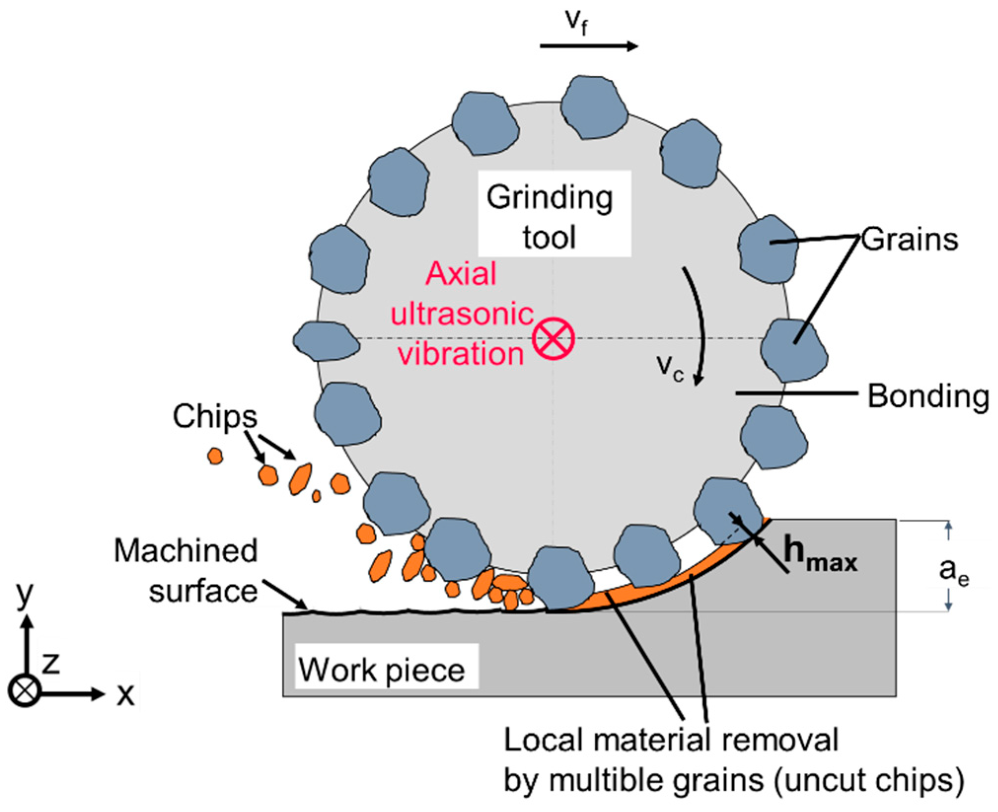
Figure 4 shows a schematic model of the material removal during the applied down-grinding process. Due to the irregular shape and position of the abrasive grains, as well as the multiple engagements with the workpiece material, the mean uncut chip thickness hmax in grinding processes can only be determined by statistical approaches. The US vibration in the experiments acted perpendicular to the cutting direction and along the tool axis (z-axis).
Figure 5 shows the schematic of the setups for the amplitude detection and the load measurement grinding experiments. In order to measure the default US amplitude contour, UAG was performed on a stack consisting of a 0.1 mm thick metal sheet and a 7.0 mm thick Cesic® specimen, which was fixed by gluing (Figure 5A). The side surface of the stack was machined by the abrasive grains located along the circumference of the grinding tool (so-called contour grinding). The tool axis and the ultrasonic vibration were parallel to the machined surface.
In contrast, for the force measurement, parallel tool paths spaced 2.0 mm apart were face ground on the surface of the Cesic® specimen Figure 5B. The abrasive grains arranged along the circumference of the grinding tool performed the major part of the chip removal, whereas only elastic-resilient components interacted with the tool face. The resulting planar surface was produced by the circulating grains of the tool face. The tool axis as well as the ultrasonic vibration were therefore perpendicular to the machined surface. In this configuration, the infeed in the radial direction (2.0 mm) was greater than in the axial direction (0.015 mm).
The face grinding process of Figure 6B was also used in the pocket machining setup, shown in Figure 6A. Figure 6B illustrates a schematic of the tool path kinematic of three ground pockets with different shapes along with the area of interest (M) for the surface roughness analysis.

2.4. Process and Workpiece Characterization

Grinding forces were measured with a dynamometer (Kistler Type 9119AA2 from Kistler Instrumente AG, 8408 Winterthur, Switzerland) at a sampling rate of 10 kHz. When surface machining, the mean axial cutting load provides the best information about the tool condition and performance.
Surface roughness of the machined component was assessed by the focus variation method with an optical micro-coordinate measuring system (Alicona Infinite Focus, Bruker Austria GmbH, 80774 Raaba, Austria). The area roughness parameters Sa (arithmetic mean height) and Sq (root mean square height) were extracted according to standard DIN EN ISO 25178 [28] and evaluated using the software of the optical micro-coordinate measuring system by applying a robust Gaussian filter with a cut-off length of 0.2 mm. The measurement area was 1 × 1 mm2 at a vertical resolution of 50 nm and a lateral resolution of 0.88 μm.

3. Results and Discussion

3.1. Dependence of Ultrasonic Amplitude on Excitation Frequency

The most effective ultrasonic (US) vibration with maximum amplitude is achieved when the vibrating system—comprising the US actuator, clamping device, and grinding tool—operates at its natural frequencies. Figure 7A shows the relationship between the US amplitude of the grinding tool tip and the frequency within a frequency range between 15 kHz and 42.5 kHz. In this range the US system has three natural frequencies with local amplitude maxima, with 4.3 µm at 24.8 kHz being the largest value. The outer tool length was set to 35 mm. Its repeatability is demonstrated in Figure 7B for some frequencies close to the peak at 24.8 kHz. When clamping the tool out/in again in the tool holder and repeating the experiment to verify the accuracy of the measurement method, the natural frequency changed by about 0.4 kHz, from 24.8 kHz to 24.4 kHz. This demonstrates the sensitive behavior of such a vibration system and highlights the importance of individually tuning each tool before processing, since even a small frequency change of 0.5 kHz may lead to an amplitude decrease of approximately 10%. A variation of 1.0 kHz resulted in even higher amplitude reductions of up to 70%.
The influence of the geometry on the maximum amplitude and its corresponding US excitation frequency were analyzed for different outer-tool lengths, as shown in Figure 8. An increase in outer-tool length from 33 mm to 40 mm led to an almost linear increase in the maximum amplitude from 3.7 µm to 6.7 µm and a decrease in the natural frequency from 24.8 kHz to 23.0 kHz. The increase in the tool length elongated the overall length of the vibrating system at constant mass, which resulted in a higher amplitude at the tool tip.
However, when the outer tool length increased further to 47 mm, the maximum amplitude dropped to 4.1 µm. At this outer tool length, the grinding tool protruded so far from the collet chuck that it was no longer fully clamped and stable over the entire clamping length. For the subsequent machining experiments the outer tool length was set to 40 mm. This resulted in a US process with an amplitude of 6.7 µm at a frequency of 23.0 kHz.

3.2. Principle of Material Removal and Verification of Ultrasonic Amplitude During Machining

During diamond grinding, the tips and edges of the diamond grains act as cutting edges. The grains have an irregular shape and are randomly fixed all over a metal tool body, for instance by galvanic bonding, causing local material removal. The combined action of these micro-chipping events generates the overall material removal on the workpiece. Grinding kinematics then consist of tool rotation with a cutting speed vc and translation with a feed rate f.
Based on the grinding conditions, Malkin [29] introduced an analytical approach to calculate an idealized geometry of the uncut chip, assuming its cross-sectional shape to be normal to the cutting direction and triangular. If a US oscillation is additionally applied, the cutting path becomes more complex [25,30] and, consequently, the geometry of the uncut chip becomes so as well. Chen et al. [30] showed the geometry of uncut chips for both CG and grinding with US vibration applied in the axial direction, and concluded that UAG increases the length of the uncut chip while reducing the chip thickness.
Although chip thickness has a significant influence on the material removal mechanisms, during face grinding or pocket machining, no remarkable effects are to be expected on surface quality. As illustrated in Figure 9, the main material removal occurs at the grains along the circumference of the tool. The machined surface is generated by the secondary material removal effects of the rotating abrasive grains on the end face of the tool. The ultrasonic vibration causes the abrasive grains to temporarily lift above and sink into the workpiece, improving coolant flow into the cutting zone and promoting chip removal.
In order to verify the default US vibration in the UAG process, a metal sheet was glued onto a Cesic® specimen (Figure 10A). Since the metal sheet was very thin (0.1 mm) compared to the ceramic material (7.0 mm), it had negligible influence on the process conditions during contour UAG.
While ceramic materials primarily undergo brittle material removal mechanisms, metal materials exhibit predominantly plastic deformation. As a result, the topographies of contour-ground metal surfaces display well-defined grooves produced by the abrasive grains along the grinding direction [31]. An SEM image of the UAG topography of the metal sheet, showing typical grinding grooves, is presented in Figure 10B. The amplitude A and frequency fd of the groove oscillations closely matched the default US vibration. This method proved to be suitable for measuring the actual US vibration of the tool during the machining operation.

3.3. Influence of Ultrasonic Assistance on Grinding Load During Surface Grinding

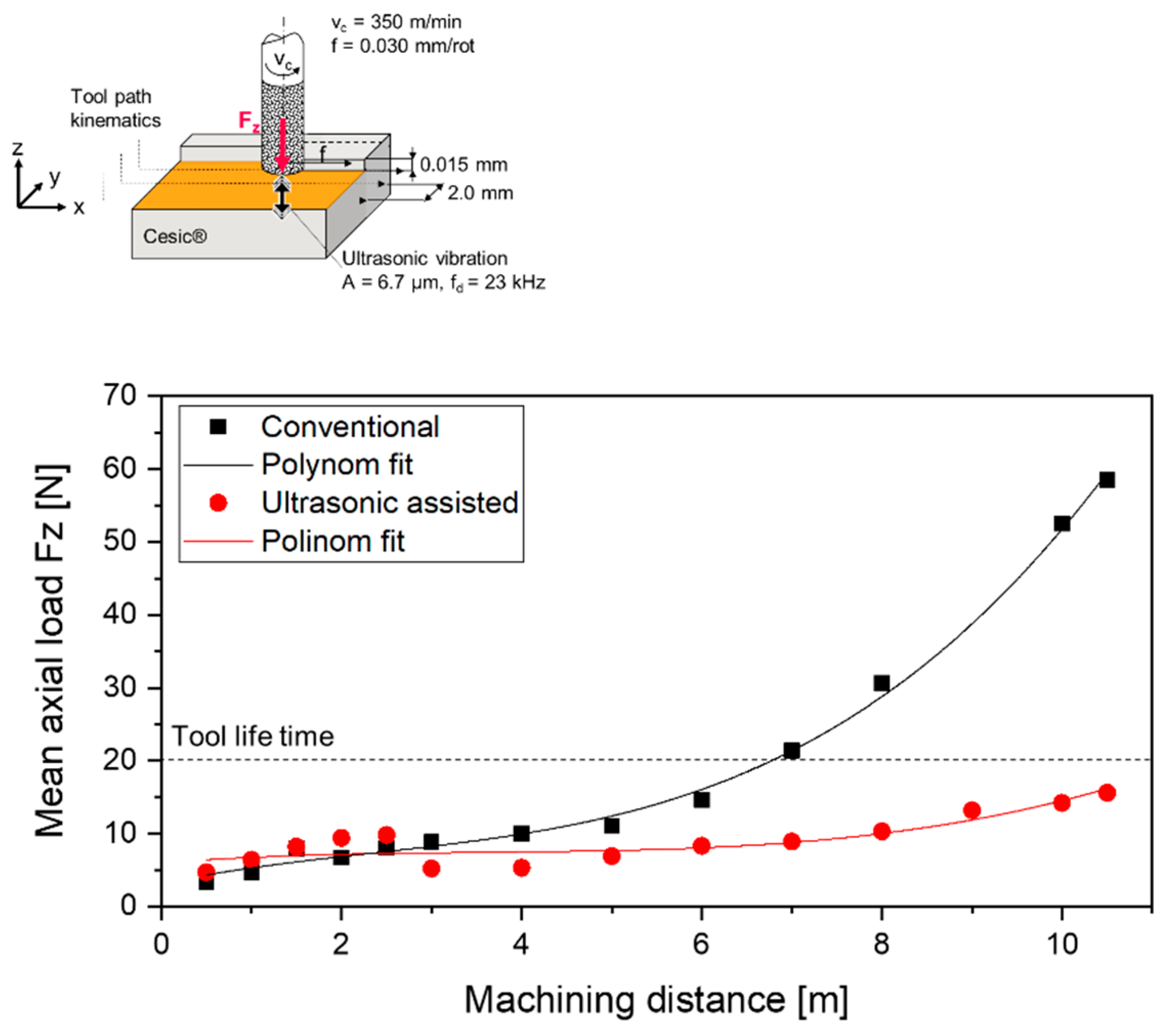
The mean axial load Fz for surface grinding is plotted in Figure 11 at a machining distance of 10.5 m for the two grinding strategies. During the first three meters, both CG and UAG showed almost constant behavior, with Fz below 10 N. Beyond this machining distance, CG exhibited a sudden increase in load, which can be approximated by a polynomial fit. The tool lifetime for CG, however, was already reached at a machining distance of approximately 6 m, corresponding to a Fz of 15 N. Further machining after this point resulted in a loss of dimensional stability of both the tool and the workpiece.
In contrast, UAG showed a different behavior. A slight increase in the axial load up to 15 N was observed when machining up to 10.5 m. At this load level, the tool showed initial signals of grain wear, and the experiment was therefore not further continued. The results evidenced an improvement of the tool life by nearly 75% for surface grinding with ultrasonic assistance, compared to CG.

3.4. Influence of Ultrasonic Assistance on Surface Roughness of Pocket Machining

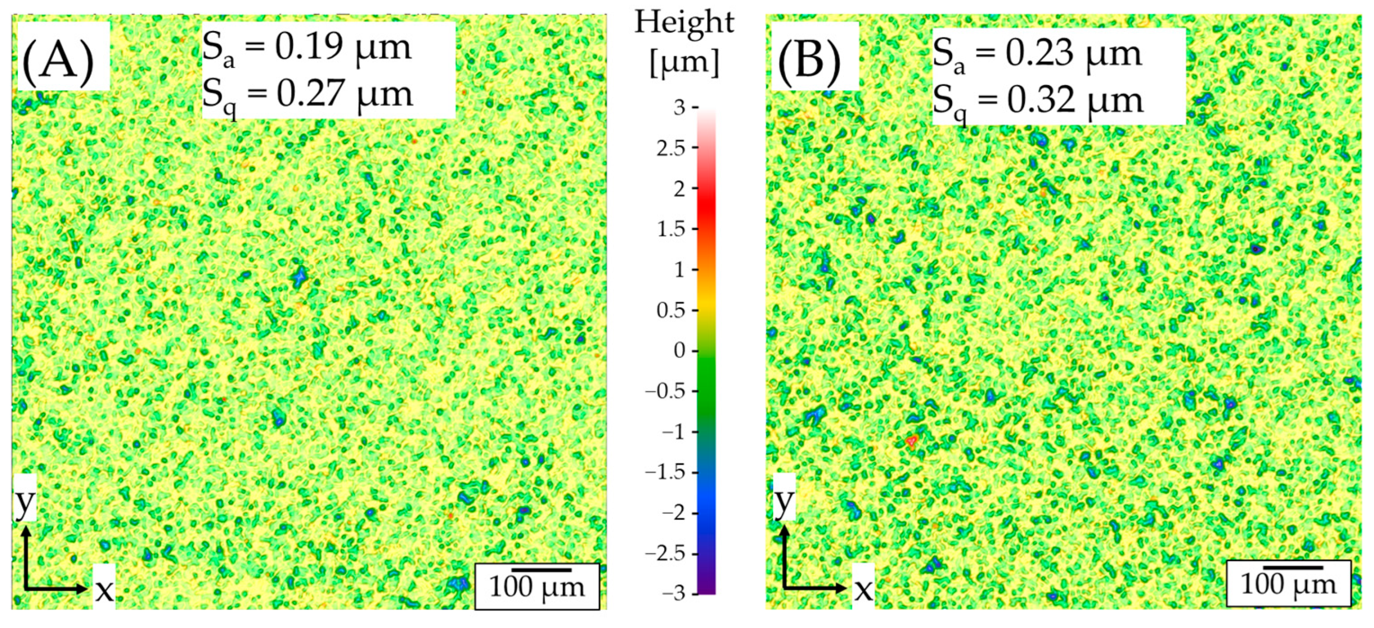
Considering the topographies of the pockets shown in Figure 12, the Sq-values generated by pocket machining are significantly lower than those by contour grinding (Sq = 0.94 µm). Moreover, no machining direction marks are observed, due to the polishing effect performed by the abrasive grains on the tool’s face following the initial material removal by the grains along the tool’s circumference. The roughness for ultrasonic-assisted ground surfaces is slightly higher (Sq = 0.32 µm, Sa = 0.23 µm) than that of CG, which is about Sq = 0.27 µm and Sa = 0.19 µm.
One plausible reason for these results is the position of roughness measurement at the second pocket, when the grinding tool has already machined the first pocket. As previously discussed, beyond a machining distance of 5 m, CG shows significantly higher load than UAG. This indicates increasing friction effects and progressing tool wear in the form of a rounding and flattening of the grain tips and edges, leading to decreasing roughness values.
Furthermore, the large US vibration amplitude (6.7 µm) during UAG may lead to an increased impact of the abrasive grains on the end face of the grinding tool on the brittle workpiece material, which systematically degrades the quality of the machined surface. Consequently, the surface roughness after UAG is higher than that after CG. These observations align with previous studies of US-assisted face grinding [23,32,33].
Despite these roughness differences, pocket machining though CG and UAG processes produced Sq-values about one order of magnitude lower compared to the preliminary sandblasted Cesic® surfaces without further final machining (Sq = 3.63 µm).
The key advantage of ultrasonic-assisted grinding (UAG) lies in its significantly higher material removal rate and machining speed compared to electrical discharge machining (EDM).
UAG of Cesic® achieves an arithmetic mean surface roughness of 0.23 µm at a removal rate of 16.7 mm3/min. In contrast, EDM processing of a similar SiSiC material with 88 vol.-% SiC content yields roughness values of 1.05 µm and 2.93 µm at much lower removal rates, ranging from 0.01 to 3.6 mm3/min [7].

3.5. Influence of Ultrasonic Assistance on Cutting Tool Wear

In order to understand the effects that lead to lower grinding forces and thus improved tool life in US-assisted machining, the end faces of the used grinding tools were further analyzed. Due to similar process conditions and machining distance (10.5 m) the grinding tools showed almost the same conditions after the face grinding and pocket machining experiments.
The microscopic images presented in Figure 13 show no remarkable wear signals for the UAG tool, but recognizable dark regions at the central area of the tool after CG. 3D-topography analysis of the tool used for UAG evidences the presence of abrasive grains at the tool face. Conversely, the end face of the tool used for CG appears smooth with no evident traces of remaining grains to further grind the material.
The SEM image in Figure 13C, however, confirmed the presence of remaining diamond grains, which were smooth polished and hindered with fine particles. Further EDX spectroscopy analysis identified Si and C elements as those particles, originating from the SiC and Si removed from the workpiece material. These detached particles clog the chip spaces between the grains on the tool face, thus reducing the performance of the tool. The US vibration may apparently avoid this effect, due to the constant accessing and flowing of coolant, improving the removal of the detached ceramic chips out of the tool–workpiece contact zone.

4. Conclusions

The ultrasonic-assisted process for the grinding of the silicon carbide composite Cesic® was evaluated, including system-specific amplitude development. The study involved both face and pocket grinding experiments, with evaluation of the arising grinding forces, workpiece surface topographies, and tool wear. From the results, the following conclusions can be drawn:
  • Amplitude Behavior: The magnitude of the ultrasonic amplitude varied with both the applied frequency and the tool’s protrusion length from the tool holder. Amplitude maxima had to be determined experimentally by identifying the natural frequencies of the complete tooling system (grinding tool, collet chuck, and tool holder). An ultrasonic amplitude of 6.7 µm was obtained for an excitation frequency of 23.0 kHz and an outer tool length of 40 mm.
  • Verification of US Vibration: The presence of ultrasonic vibration during the contour machining of Cesic® was confirmed using a fine metal sheet, demonstrating effective transmission of ultrasonic energy.
  • Grinding Forces and Tool Life: After a machining distance of 10.5 m, the mean axial load (Fz) in conventional grinding (58.5 N) reached nearly four times the value measured in ultrasonic-assisted grinding (15.6 N), respectively. Whereas during conventional grinding the grinding tool end-face was clogged by detached ceramic particles from the workpiece, ultrasonic vibration exhibited a 75% higher tool life, due to the continuous cooling effect and the improved removal of the ceramic chips out of the tool–workpiece contact zone.
  • Surface Quality and Material Removal Rate: The ultrasonic-assisted grinding of pockets in Cesic® samples at a material removal rate of 16.7 mm3/min achieved an arithmetic mean roughness value of Sa = 0.23 µm; significantly lower than the more-than-1.05 µm obtained by EDM in previous studies on similar SiSiC materials and with lower material removal rates (0.01–3.6 mm3/min) [7].

Author Contributions

Conceptualization, A.R.; methodology, A.R.; validation, A.R., P.L.-P. and R.G.; formal analysis, A.R.; investigation, A.R.; resources, A.R. and P.L.-P.; data curation, A.R.; writing—original draft preparation, A.R.; writing—review and editing, A.R., P.L.-P., J.M. and R.G.; visualization, A.R.; supervision, R.G.; project administration, A.R. and J.M.; funding acquisition, A.R. and R.G. All authors have read and agreed to the published version of the manuscript.

Funding

The work in this article was supported by the German Federal Ministry for Economic Affairs and Energy (BMWE), Project No. 20Q1945C: Development of a data-based process control system for the machining of CMC (ceramic matrix composite) aerospace turbine components.

Data Availability Statement

The data that support the findings of this study are available from the corresponding author (A.R.), upon reasonable request.

Conflicts of Interest

Author Joshua Macken was employed by the company Hufschmied Zerspanungssysteme GmbH. The remaining authors declare that the research was conducted in the absence of any commercial or financial relationships that could be construed as a potential conflict of interest.

Abbreviations

CGConventional grinding
EDMElectrical Discharge Machining
UAGUltrasonic Assisted Grinding
USUltrasonic

References

  1. Krödel, M.; Ozaki, T. Dynamic performance of HB-Cesic® under severe Conditions and its applications. In Proceedings of the 18th International Conference of Composite Materials, Jeju Island, Republic of Korea, 21–26 August 2011. [Google Scholar]
  2. Krenkel, W. Entwicklung eines Kostengünstigen Verfahrens zur Herstellung von Bauteilen aus Keramischen Verbundwerkstoffen. Ph.D. Thesis, Deutsches Zentrum für Luft- und Raumfahrt, Cologne, Germany, 2000. [Google Scholar]
  3. Krödel, M.; Ku, J.; Langton, J.B.; Schindler, R.H.; Wahl, B. The rigid and thermally stable all-ceramic LSST camera: Focal plane from design to assembly. In Ground-Based and Airborne Instrumentation for Astronomy VII; SPIE: Bellingham, WA, USA, 2018. [Google Scholar]
  4. Krödel, M.R.; Devilliers, C. SPIRALE: The first all-Cesic® telescopes orbiting earth. In Optical Materials and Structures Technologies IV; SPIE: Bellingham, WA, USA, 2009; p. 74250F. [Google Scholar]
  5. Krödel, M.; Ozaki, T.; Kume, M.; Yui, Y.Y.; Imai, H.; Katayama, H.; Tange, Y.; Nakagawa, T. Manufacturing and performance test of a 800 mm space optic. In Optical Manufacturing and Testing VIII; SPIE: Bellingham, WA, USA, 2009; Volume 7426, p. 74260K. [Google Scholar]
  6. Krödel, M.; Komadina, J.; Perrin, L.; Berill, M. MTG star tracker assembly bracket: A successful story of fabrication story of light-weighted structures. In Material Technologies and Applications to Optics, Structures, Components, and Sub-Systems IV; SPIE: Bellingham, WA, USA, 2019. [Google Scholar]
  7. Kliuev, M.; Maradia, U.; Boccadoro, M.; Perez, R.; Stirnimann, J.; Wegener, K. Experimental Study of EDM-Drilling and Shaping of SiSiC and SiC. Procedia CIRP 2016, 42, 191–196. [Google Scholar] [CrossRef]
  8. Clijsters, S.; Liu, K.; Reynaerts, D.; Lauwers, B. EDM technology and strategy development for the manufacturing of complex parts in SiSiC. J. Mater. Process. Technol. 2010, 210, 631–641. [Google Scholar] [CrossRef]
  9. Yin, L.; Vancoille, E.; Lee, L.; Huang, H.; Ramesh, K.; Liu, X. High-quality grinding of polycrystalline silicon carbide spherical surfaces. Wear 2004, 256, 197–207. [Google Scholar] [CrossRef]
  10. Chen, S.; Cheung, C.; Zhao, C.; Zhang, F. Simulated and measured surface roughness in high-speed grinding of silicon carbide wafers. Int. J. Adv. Manuf. Technol. 2017, 91, 719–730. [Google Scholar] [CrossRef]
  11. Horvath, N.; Honeycutt, A.; Davies, M.A. Grinding of additively manufactured silicon carbide surfaces for optical applications. CIRP Ann. 2020, 69, 509–512. [Google Scholar] [CrossRef]
  12. Beaucamp, A.; Namba, Y.; Combrinck, H.; Charlton, P.; Freeman, R. Shape adaptive grinding of CVD silicon carbide. CIRP Ann. 2014, 63, 317–320. [Google Scholar] [CrossRef]
  13. Agarwal, S.; Rao, P.V. Grinding characteristics, material removal and damage formation mechanisms in high removal rate grinding of silicon carbide. Int. J. Mach. Tools Manuf. 2010, 50, 1077–1087. [Google Scholar] [CrossRef]
  14. Harrer, W.; Danzer, R.; Rendtel, A. Influence of the surface condition on the biaxial strength of a commercial silicon carbide. J. Eur. Ceram. Soc. 2016, 36, 3895–3900. [Google Scholar] [CrossRef]
  15. Uhlmann, E.G. Tiefschleifen Hochfester Keramischer Werkstoffe; Hanser: München, Germany, 1994. [Google Scholar]
  16. Teichert, C.; MacKay, J.F.; Savage, D.E.; Lagally, M.G.; Brohl, M.; Wagner, P. Comparison of surface roughness of polished silicon wafers measured by light scattering topography, soft-x-ray scattering, and atomic-force microscopy. Appl. Phys. Lett. 1995, 66, 2346–2348. [Google Scholar] [CrossRef]
  17. Zhao, Y.; Chang, L. A micro-contact and wear model for chemical–mechanical polishing of silicon wafers. Wear 2002, 252, 220–226. [Google Scholar]
  18. Ozturk, S.; Aydin, L.; Kucukdogan, N.; Celik, E. Optimization of lapping processes of silicon wafer for photovoltaic applications. Sol. Energy 2018, 164, 1–11. [Google Scholar] [CrossRef]
  19. Young, H.T.; Liao, H.T.; Huang, H.Y. Surface integrity of silicon wafers in ultra precision machining. Int. J. Adv. Manuf. Technol. 2006, 29, 372–378. [Google Scholar] [CrossRef]
  20. Goel, S.; Luo, X.; Reuben, R.L. Wear mechanism of diamond tools against single crystal silicon in single point diamond turning process. Tribol. Int. 2013, 57, 272–281. [Google Scholar] [CrossRef]
  21. Leung, T.; Lee, W.; Lu, X. Diamond turning of silicon substrates in ductile-regime. J. Mater. Process. Technol. 1998, 73, 42–48. [Google Scholar] [CrossRef]
  22. Yan, J.; Zhang, Z.; Kuriyagawa, T. Mechanism for material removal in diamond turning of reaction-bonded silicon carbide. Int. J. Mach. Tools Manuf. 2009, 49, 366–374. [Google Scholar] [CrossRef]
  23. Chen, Y.; Su, H.; Qian, N.; He, J.; Gu, J.; Xu, J.; Ding, K. Ultrasonic vibration-assisted grinding of silicon carbide ceramics based on actual amplitude measurement: Grinding force and surface quality. Ceram. Int. 2021, 47, 15433–15441. [Google Scholar] [CrossRef]
  24. Churi, N.J.; Pei, Z.J.; Shorter, D.C.; Treadwell, C. Rotary ultrasonic machining of silicon carbide: Designed experiments. Int. J. Manuf. Technol. Manag. 2007, 12, 284–298. [Google Scholar] [CrossRef]
  25. Ding, K.; Fu, Y.; Su, H.; Cui, F.; Li, Q.; Lei, W.; Xu, H. Study on surface/subsurface breakage in ultrasonic assisted grinding of C/SiC composites. Int. J. Adv. Manuf. Technol. 2017, 91, 3095–3105. [Google Scholar] [CrossRef]
  26. Uhlmann, E.; Daus, N.-A. Ultraschallunterstütztes Schleifen–Einsatzvorteile Durch ein Innovatives Schleifverfahren, Universitätsbibliothek u. Technische Informationsbibliothek; Institut für Werkzeugmaschinen und Fabrikbetrieb: Berlin, Germany, 2001. [Google Scholar]
  27. Rösiger, A. Einfluss der Schleif- und Fräsbearbeitung auf die Oberflächenqualität und die Mechanischen Eigenschaften von Kohlenstofffaserverstärktem Siliziumcarbid. Ph.D. Thesis, Cuvillier Verlag, Göttingen, Germany, 2022. [Google Scholar]
  28. ISO 25178-2:2021; Geometrical Product Specifications (GPS)—Surface Texture: Areal—Part 2: Terms, Definitions and Surface Texture Parameters. ISO: Geneva, Switzerland, 2021.
  29. Malkin, S. Grinding Technology: Theory and Applications of Machining with Abrasives, 2nd ed.; Industrial Press: New York, NY, USA, 2008. [Google Scholar]
  30. Chen, J.; An, Q.; Ming, W.; Chen, M. Investigation on machined surface quality in ultrasonic-assisted grinding of Cf/SiC composites based on fracture mechanism of carbon fibers. Int. J. Adv. Manuf. Technol. 2020, 109, 1583–1599. [Google Scholar] [CrossRef]
  31. Rösiger, A.; Schukraft, J.; Goller, R.; Weidenmann, K.A. Investigation of the mechanical machinability of an interpenetrating metal-ceramic composite using diamond grinding. Int. J. Adv. Manuf. Technol. 2025, 136, 5625–5639. [Google Scholar] [CrossRef]
  32. Wdowik, R.; Porzycki, J.; Magdziak, M. Measurements of Surface Texture Parameters After Ultrasonic Assisted and Conventional Grinding of ZrO2 Based Ceramic Material Characterized by Different States of Sintering. Procedia CIRP 2017, 62, 293–298. [Google Scholar] [CrossRef]
  33. Ding, K.; Fu, Y.; Su, H.; Gong, X.; Wu, K. Wear of diamond grinding wheel in ultrasonic vibration-assisted grinding of silicon carbide. Int. J. Adv. Manuf. Technol. 2014, 71, 1929–1938. [Google Scholar] [CrossRef]
Figure 1. SEM image of the Cesic® microstructure of a polished sample. C-fibers are represented by the darker areas, whereas the gray regions are SiC with Si (white spots).
Jmmp 09 00346 g001
Figure 2. Sketch and microscopical image of the grinding tool (left side) and microscopic image of the electroplated diamond grains (right side).
Jmmp 09 00346 g002
Figure 3. (A) Schematic model and image of the US vibrating system and (B) image of the experimental setup of the US-amplitude measurement.
Jmmp 09 00346 g003
Figure 4. Schematic model for the maximum uncut chip thickness hmax of the down-grinding process and the direction of ultrasonic vibration.
Jmmp 09 00346 g004
Figure 5. Schematic of the machining setup for (A) the ultrasonic amplitude detection during contour grinding, and (B) the grinding load measuring during face grinding.
Jmmp 09 00346 g005
Figure 6. (A) Setup for pocket machining on Cesic® material with (B) schematic of tool path kinematic showing surface measurement area of interest (M).
Jmmp 09 00346 g006
Figure 7. (A) Ultrasonic amplitude as a function of the default frequency. (B) Repeatability of the ultrasonic amplitude as a function of the default frequency from 22 kHz to 28 kHz.
Jmmp 09 00346 g007
Figure 8. Maximum measured ultrasonic amplitude and excitation frequency as a function of the outer tool length.
Jmmp 09 00346 g008
Figure 9. Schematic illustration of the material removal process during face grinding with axial ultrasonic assistance.
Jmmp 09 00346 g009
Figure 10. (A) Contour machined stack metal sheet and Cesic® materials, (B) SEM image of the ultrasonic-assisted ground surface of the metal sheet.
Jmmp 09 00346 g010
Figure 11. Mean axial load Fz depending on the machining distance for CG and UAG.
Jmmp 09 00346 g011
Figure 12. Topographies of machined pockets in Cesic® material after (A) conventional and (B) ultrasonic-assisted grinding.
Jmmp 09 00346 g012
Figure 13. Microscopic image of the grinding tool’s end face with the 3D-topography after pocket machining for (A) conventional and (B) ultrasonic-assisted grinding, and (C) SEM image of the tool’s end face after conventional grinding.
Jmmp 09 00346 g013
Table 1. Summary of physical and mechanical properties of Cesic® [1,3,4].
PropertyValue
Density [g/cm3]2.97
Bending strength [MPa]320
Young’s modulus [GPa]350
Fracture toughness Kic [MPa·m1/2]3.7
Poisson’s ratio0.18
Coefficient of thermal expansion 313 K-293 K [10−6/K]2.3
Thermal conductivity RT [W/(m·K)]125
Disclaimer/Publisher’s Note: The statements, opinions and data contained in all publications are solely those of the individual author(s) and contributor(s) and not of MDPI and/or the editor(s). MDPI and/or the editor(s) disclaim responsibility for any injury to people or property resulting from any ideas, methods, instructions or products referred to in the content.