Article

Introduction of Functional Elements with Double-Sided Self-Pierce Riveting

by
Rafael M. Afonso
1,2,* and
Luís M. Alves
3
1
Engineering Department, Atlântica University Institute, Fábrica da Pólvora de Barcarena, 2730-036 Oeiras, Portugal
2
Centre for Mechanical and Aerospace Science and Technologies (C-MAST), University of Beira Interior, Rua Marquês d’Ávila e Bolama, 6201-001 Covilhã, Portugal
3
IDMEC, Instituto Superior Técnico, University of Lisbon, Av. Rovisco Pais 1, 1049-001 Lisboa, Portugal
*
Author to whom correspondence should be addressed.
J. Manuf. Mater. Process. 2025, 9(10), 344; https://doi.org/10.3390/jmmp9100344
Submission received: 30 September 2025 / Revised: 14 October 2025 / Accepted: 16 October 2025 / Published: 20 October 2025
(This article belongs to the Special Issue Advances in Material Forming: 2nd Edition)

Abstract

The introduction of functional elements is essential for many industrial components which rely on elements such as bolts, screws, nuts, or clips that are integrated into the workpieces. In the field of cold joining technologies, double-sided self-pierce riveting (DS-SPR) presents itself as a proper alternative to produce the mechanical connection of those elements into sheet panels. For the purpose of this investigation, a tubular rivet with a machined thread to replicate a hollow bolt was joined to a sheet panel. Since this application will be subjected to torsion loads when a nut or other elements are fastened, tubular rivets with different numbers of semi-longitudinal rectangular openings at their ends (0, 2, 4, and 8) were investigated to identify the optimal design that ensures proper performance during its service life. The results show that rivets with four openings achieved a torsional resistance of more than 40 N·m, which is over double that of the original rivet without openings, while maintaining comparable shear strength (~10 kN). A functional hollow bolt with an outer thread was successfully produced, achieving a torque capacity of 35 N·m, equivalent to an M8 solid bolt, but with reduced weight. These findings highlight DS-SPR as a viable technology for manufacturing functional riveted elements that combine the permanent joints between sheets and removable connections with secondary components, offering both structural performance and lightweight advantages.

1. Introduction

The utilization of the riveting technology of double-sided self-pierce riveting (DS-SPR) [1] presents a cost-effective solution that can be easily automated with consistent quality and produced with lower levels of force and energy [2,3]. Functional elements have already been proven in a wide range of applications across different industries, as they can take various forms such as bolts, screws, nuts, or clips and be integrated into sheet panels to enable attachment to other components. Forming operations [4,5,6,7,8] and additive manufacturing technologies [9] have also been employed to produce these functional elements in sheet metal, although the range of material combinations remains limited.
Compared to other joining-by-forming technologies [10] for producing riveted connections [11], such as self-pierce riveting (SPR) [12,13,14], DS-SPR uses a tubular rivet of simple geometry positioned between the sheets and driven through the workpieces using non-complex tools (Figure 1a), resulting in the flaring of the rivet ends to create a mechanical interlock. Initially developed for joining overlapped sheets of different materials [15] and thicknesses [16], DS-SPR principles have since been extended to other configurations [17], including the joining of tubes to sheets (SPR-TS) [18] (Figure 1b).
However, current DS-SPR research has focused primarily on structural joints, with limited attention to integrating functional elements such as threaded rivets capable of withstanding torsional loads. This gap is critical for applications in automotive, aerospace, and lightweight structures, where combining permanent and removable joints in a single process can reduce assembly complexity and weight. Recent studies have highlighted DS-SPR’s potential for multi-material joining and its adaptability for advanced manufacturing [19,20,21], as well as its role in sustainable lightweight design [22].
To address this gap, the present work investigates the feasibility of producing functional riveted elements using DS-SPR. Tubular rivets with different numbers of semi-longitudinal rectangular openings were tested to enhance torsional resistance without compromising shear performance. These openings are expected to improve material flow during deformation and increase the mechanical interlock, thereby improving torsional strength. The different configurations tested are presented in Figure 2, which shows rivets with 0, 2, 4, and 8 openings at each end.
Based on these results, a rivet with the optimal number of semi-longitudinal cuts and an outer threaded surface was machined and joined to a single AA5754 sheet using the modified tool setup shown in Figure 1b. The results show how the hollow bolt compares with a solid bolt with the same specification and material, highlighting performance and weight advantages of the DS-SPR-produced functional element. Destructive torsion and shear tests are employed to evaluate the mechanical performance of the different joints produced during experimentation.

2. Materials and Methods

2.1. Material Selection and Equipment

The materials used for the rivets (functional elements) and sheets were the same as those employed in previous DS-SPR studies [1]. The rivets were manufactured from stainless steel AISI 304, and the sheets were made of aluminum alloy AA5754-H111, representing a common dissimilar joint configuration in lightweight assemblies. These materials were supplied by Poly Lanema Lda, located in Ovar, Portugal. The mechanical behavior of both materials was characterized using flow curves approximated by the Ludwik–Holomon power-law hardening model, as shown in Table 1.
The tubular rivet geometry followed the successful configuration established in [1], with an outer diameter d0 = 10 mm, wall thickness t0 = 1.5 mm, and initial height h0 = 8 mm. The rivet featured a α = 30° chamfer at each end to promote symmetrical flaring during deformation. The sheet thickness was ts = 5 mm for all joints (refer to Figure 1 for the previous parameters).
Each configuration was tested three times to ensure reproducibility, and average values are reported. The variance between repetitions remained within ±5% for shear and ±8% for torsion tests, confirming consistent performance across all samples. Since AISI 304 and AA5754 form a dissimilar metal pair, galvanic corrosion may occur under certain environments. No surface treatment was applied in this exploratory phase; however, future work will address anodizing or other coatings to mitigate galvanic effects.
Mechanical characterization [23] and joining tests were performed on an Instron SATEC 1200 kN hydraulic testing machine at 10 mm/min. To evaluate joint performance, destructive torsion and shear tests were conducted on different machines with dedicated tool setups.
  • Shear tests followed ISO 12996:2013 [24] and were performed on an Instron 5900R hydraulic testing machine at a crosshead speed of 5 mm/min. The test setup is shown in Figure 3a.
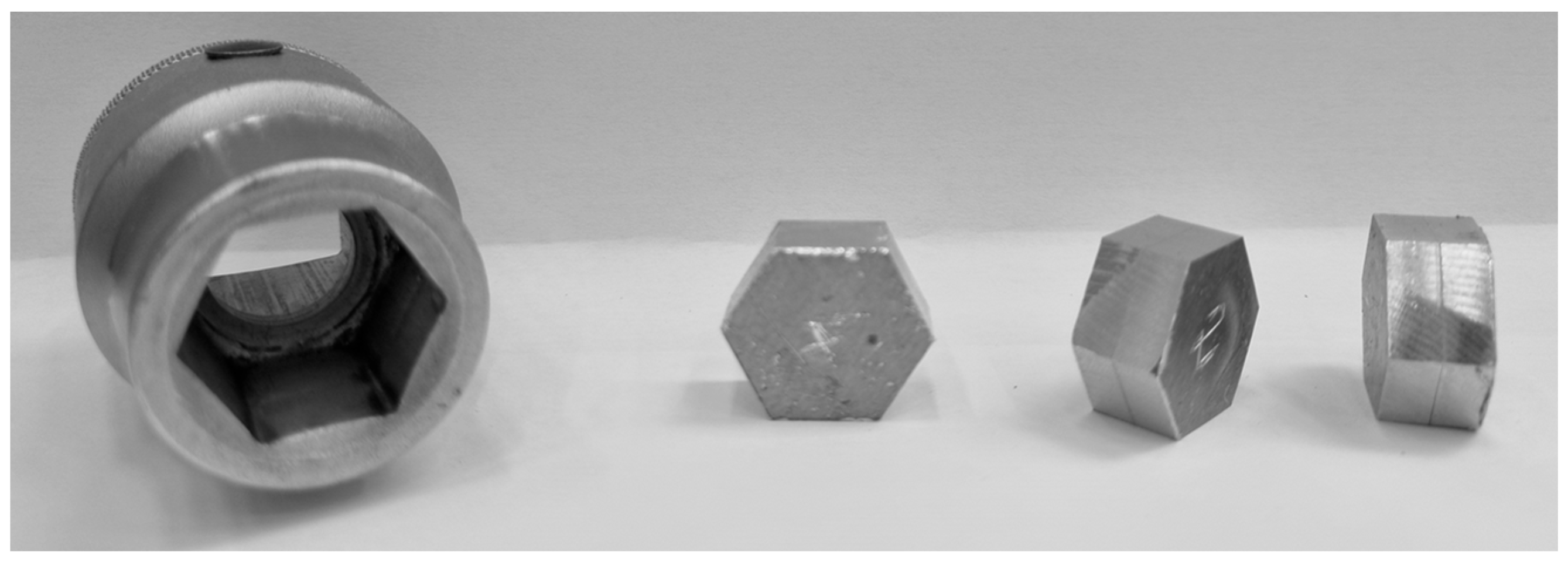
  • Torsion tests followed ISO 18338:2015 [25] and were carried out on a GUNT WP510 torsion testing machine (Figure 3b) at a rotation speed of 50°/min. This machine features a stationary and a moving head, enabling the application of torsional loads to the specimen. Due to the shape of the torsion heads, specimens were machined into a hexagonal profile, as illustrated in Figure 4.

2.2. Work Development

To determine the optimal rivet configuration for functional elements, the experimental plan outlined in Table 2 was followed. The first stage aimed to identify the best number of semi-longitudinal rectangular openings at each rivet end. The experimental plan included four rivet configurations with 0, 2, 4, and 8 semi-longitudinal rectangular openings at each end. Each configuration was used to join two AA5754 sheets with a thickness of 5 mm. The joining force, deformation behavior, and mechanical performance were evaluated through destructive shear and torsion tests. After determining the optimal number of openings, an outer thread was machined on the selected tubular rivet to replicate a hollow bolt configuration. The threaded rivet had an initial height of 25 mm and was joined to a single AA5754 sheet using a modified tool setup. Shear tests were performed on an Instron 5900R hydraulic testing machine at a crosshead speed of 5 mm/min following ISO 12996:2013, and torsion tests were carried out on a GUNT WP510 machine at a rotation speed of 50°/min following ISO 18338:2015 [25]. The temperature rise during joining was not measured, as the deformation rate and process duration were low. Based on previous DS-SPR studies [1,16,19], the thermal effects are considered negligible.
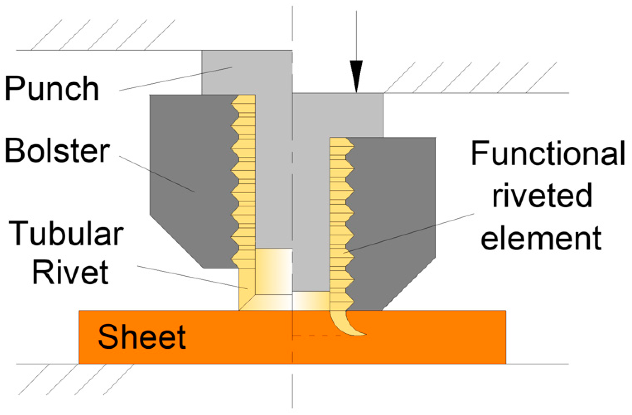
After identifying the optimal rivet configuration, an outer thread was machined on the tubular rivet to replicate a hollow bolt. The rivet dimensions remained the same as in previous stages, except for an increased initial height (h0 = 25 mm) to accommodate the threaded section. The optimized rivet was then joined to a single AA5754 sheet using a modified tool setup (Figure 1b) and tested to evaluate its mechanical performance.

3. Results

Influence of the Longitudinal Openings on the Riveting Operation

The introduction of semi-longitudinal rectangular openings along the tubular rivet wall significantly influences its deformation during the DS-SPR process. Experimental observations indicate that these openings do not strongly affect rivet penetration because the increase in wall thickness caused by axial compression and strain hardening tends to close the openings (refer to Figure 5). However, the openings reduce circumferential stress during the clamping stage, promoting greater flaring of the rivet ends and improving the undercut. For instance, a rivet with two openings achieved an average undercut of 1.23 ± 0.05 mm, compared to 0.87 ± 0.04 mm for the original rivet—representing a 41% increase. The undercut and rivet head height were measured for each joint, and the variations remained below 0.1 mm, confirming the consistency and repeatability of the process.
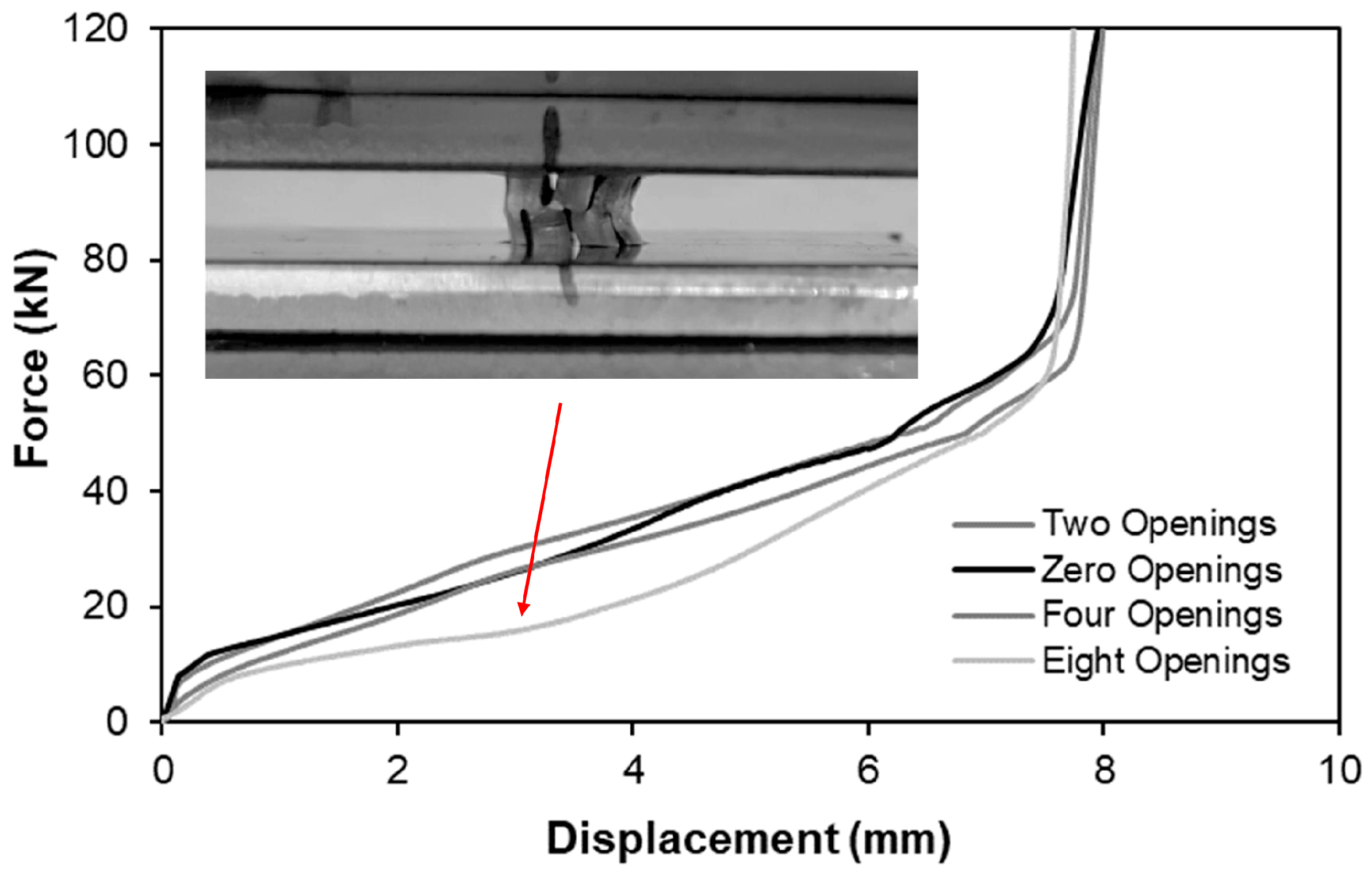
Despite this, the force–displacement curves in Figure 6 show that the joining force remains similar for rivets with two and four openings compared to the original rivet. Differences become more evident at higher displacements, where reduced circumferential constraint allows easier material flow into the openings. Conversely, rivets with eight openings exhibit early plastic instability, limiting penetration and resulting in a weak joint. Therefore, the maximum feasible number of openings for this rivet material is eight, beyond which structural integrity is compromised.
To validate the improvements introduced by different opening configurations and compare them with conventional tubular rivets, destructive shear and torsion tests were conducted. These tests are particularly relevant for assessing the performance of DS-SPR joints when used as functional elements subjected to torsional loads during service.

4. Discussion

4.1. Analysis of the Performance of the Riveted Joint

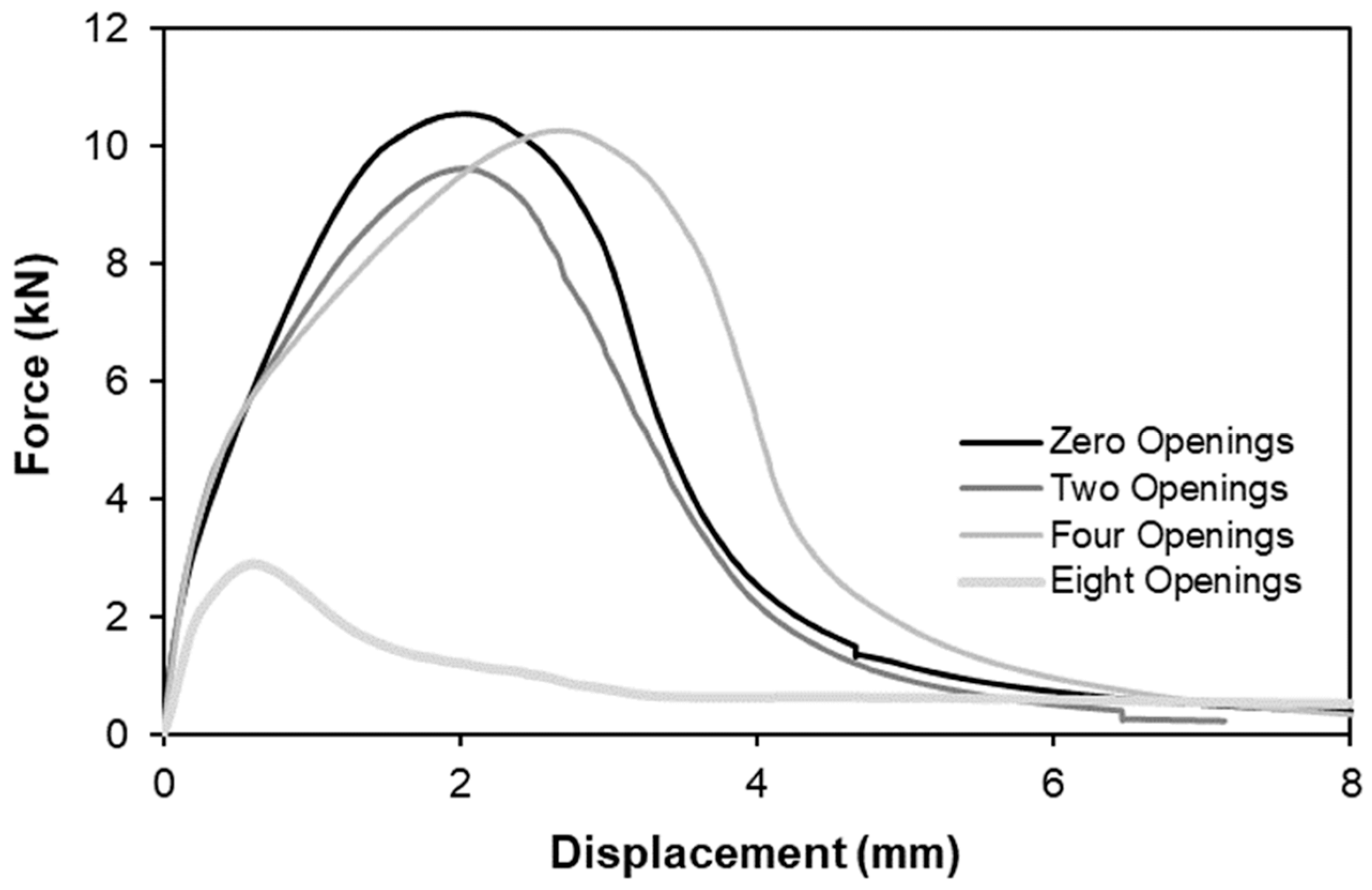
To assess the performance gains resulting from the introduction of semi-longitudinal rectangular openings, each joint configuration was analyzed through destructive shear and torsion tests. The results of the shear tests are presented in Figure 7, showing that the peak force values are similar across most configurations, except for the rivet with eight openings, which exhibited plastic instability during joining and therefore failed at a much lower load.
The rivet without openings achieved the highest shear strength (10.5 kN), while rivets with two and four openings showed slightly lower values, differing by approximately 1.0 kN and 0.3 kN, respectively. These small differences are attributed to the reduced resistant area during sheet detachment, as illustrated in Figure 8. Although sheet material flowed into the openings, the localized reduction in the cross-sectional area during failure explains the minor decrease in shear resistance.
Morphological analysis of the failed specimens (Figure 8a,c) confirms similar deformation patterns for rivets with 0, 2, and 4 openings, while the specimen with eight openings (Figure 8d) shows incomplete penetration and early failure. This confirms that excessive openings compromise joint integrity.
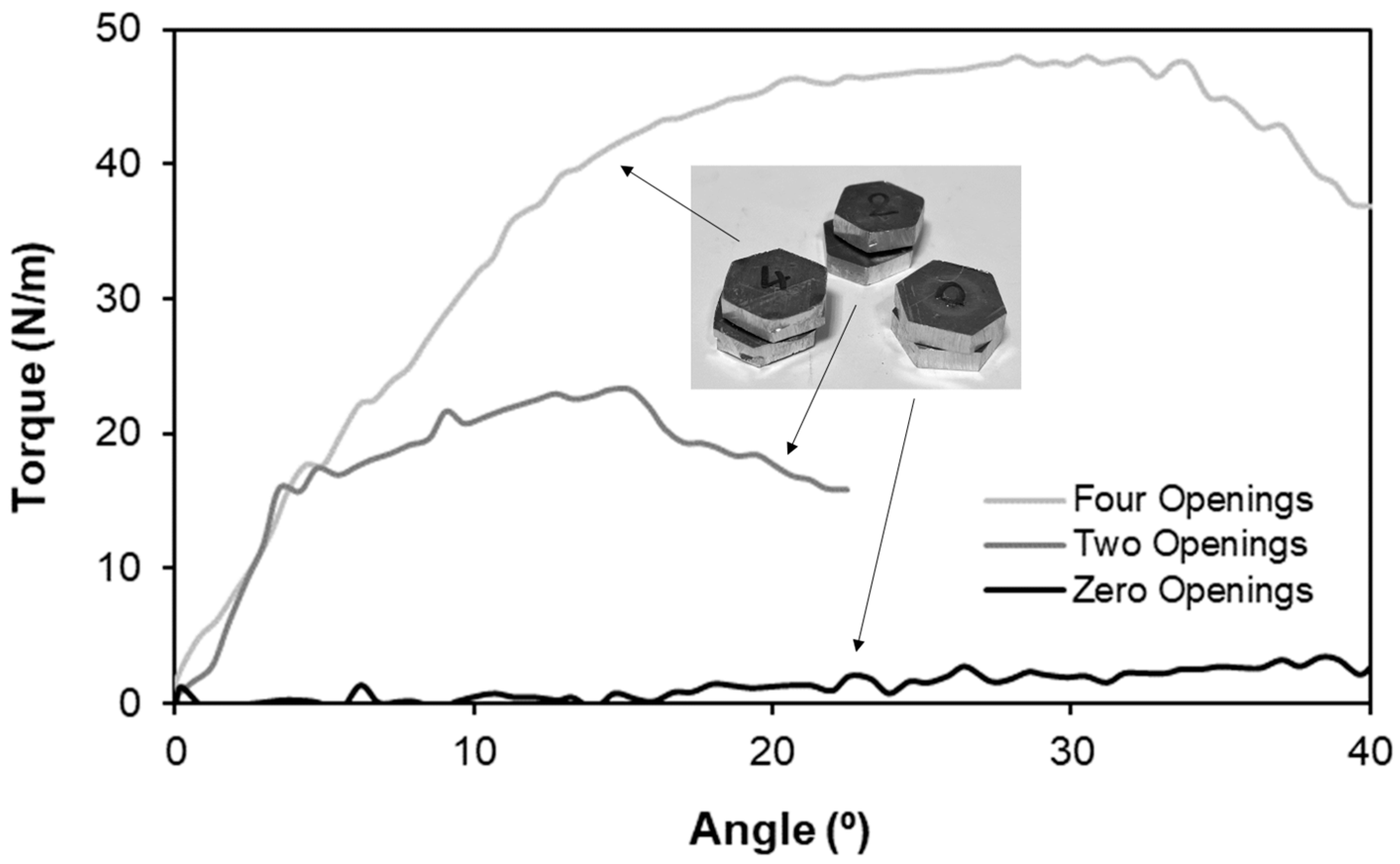
While shear performance remained relatively unaffected, torsional resistance improved significantly with the introduction of openings. The material flow into the openings created additional interlocking surfaces, increasing the resistant area against rotation. As shown in Figure 9, torsional strength increased proportionally with the number of openings:
  • 2 openings: +20 N·m compared to the original rivet;
  • 4 openings: >40 N·m, more than double the original value.
This demonstrates that torsional performance is strongly dependent on the number of openings, whereas shear strength remains nearly constant.

4.2. Assessment of the Functional Rivet Element

Based on these findings, a rivet with four openings was selected as the optimal configuration for producing a functional element. This rivet was machined with an outer thread on one end, enabling the creation of a permanent joint with the sheet and a removable joint at the threaded end. The joining process was carried out using the dedicated tool system shown in Figure 10, designed to protect the threaded surface while ensuring proper deformation of the opposite end.
The preforms and final joint are shown in Figure 11, including a cross-sectional view confirming a sound joint with an undercut similar to that of previous tests. A nut was successfully fastened to the threaded section, demonstrating full functionality.
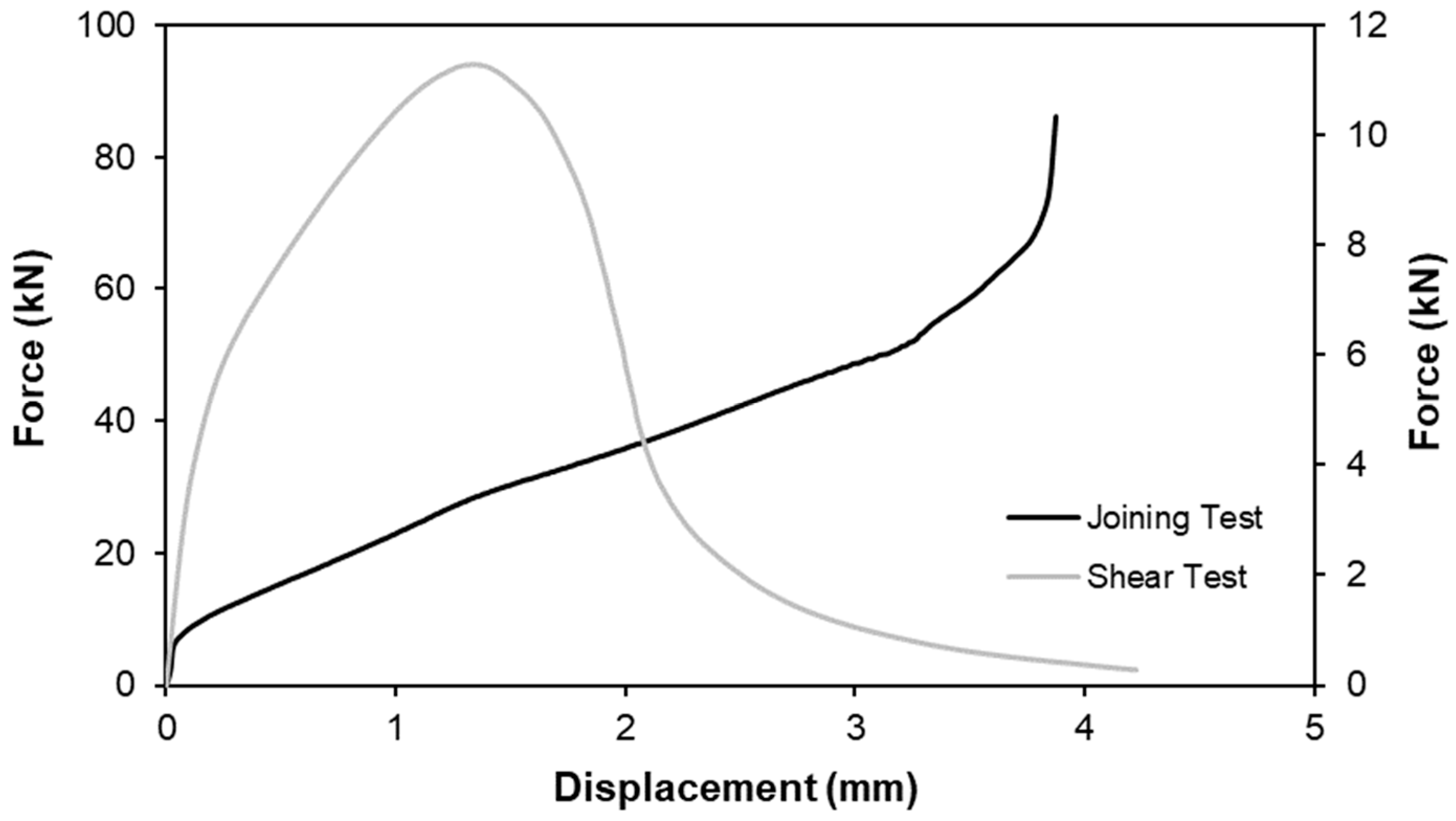
The joining and mechanical performance of the functional rivet element were evaluated through destructive shear and torque testing. The joining force was slightly lower than in the previous two-sheet configuration because the rivet penetrated only a single sheet, resulting in reduced strain hardening. Displacement was also about half that of the double-sheet case for the same reason. The functional element demonstrated excellent thread integrity. The threads were inspected visually and functionally by fastening a standard M10 nut, which engaged smoothly without deformation or misalignment. The nut could be tightened up to 35 N·m before rotation occurred relative to the sheet, confirming the quality of the formed threads. Furthermore, the hollow M10 rivet provided a 30% mass reduction compared to a solid M8 bolt of equivalent torsional capacity, demonstrating the lightweight potential of DSSPR-manufactured functional elements. The corresponding force–displacement curves for joining and destructive shear testing are shown in Figure 12.
The trends observed in this study are consistent with previous findings on the role of geometric features in enhancing joint performance. Other authors [4,5,6,7,8] reported that introducing cavities or openings in sheet-bulk forming operations increases local material flow and mechanical interlocking, which aligns with the present torsional resistance improvements. When compared with conventional self-pierce riveting (SPR) technologies [12,13,14], the DS-SPR process achieves similar shear strength while providing superior torsional resistance due to the additional interlocking surfaces formed by the openings. These comparisons reinforce the originality and scientific relevance of the present investigation, highlighting DS-SPR as a promising technique for the integration of functional elements into lightweight structures.

5. Conclusions

The introduction of semi-longitudinal rectangular openings at the rivet ends proved to be an effective strategy for producing functional riveted elements in sheet panels. Rivets with four openings achieved a torsional resistance exceeding 40 N·m—more than double that of the original rivet without openings—while maintaining a shear strength of approximately 10 kN. The mechanical interlocking achieved through the openings significantly improved rotational resistance without compromising shear performance. A functional rivet element with four openings and an external thread was successfully produced, exhibiting a torque capacity of 35 N·m, equivalent to a solid M8 bolt, while achieving a 30% reduction in mass.
The DS-SPR process demonstrated reliable performance and repeatability across all tested configurations. Future work will focus on finite element simulations to optimize rivet geometry and material flow. Additional investigations will address cyclic and fatigue testing under torsional and shear loads to evaluate long-term durability. Although galvanic corrosion was not considered in the present work, surface treatment strategies will be assessed to extend the applicability of DS-SPR to dissimilar metallic systems. The process remains most effective for total sheet stack thicknesses up to approximately 6 mm for aluminum and mild steels, whereas for harder materials such as DP600, the required process forces and the risk of rivet fracture increase significantly, constraining its use without geometric optimization. Nevertheless, the technology can be extended to multi-layer joints through the selection of suitable rivet geometries and die designs, as demonstrated in reference [17].
The findings of this investigation confirm DS-SPR as a viable technology for manufacturing functional riveted elements that combine permanent and removable joints within lightweight assemblies.

Author Contributions

Conceptualization, R.M.A.; Data curation, R.M.A.; Formal analysis, R.M.A. and L.M.A.; Investigation, R.M.A. and L.M.A.; Methodology, R.M.A.; Supervision, R.M.A.; Validation, R.M.A. and L.M.A.; Writing—original draft, R.M.A.; Writing—review and editing, R.M.A. and L.M.A. All authors have read and agreed to the published version of the manuscript.

Funding

This research was supported by FCT/MCTES through national funds (PIDDAC) under the R&D Unit C-MAST/Center for Mechanical and Aerospace Science and Technologies, UIDB/00151/2020 (DOI: 10.54499/UIDB/00151/2020 & DOI: UIDP/00151/2020). The authors also acknowledge Fundação para a Ciência e a Tecnologia (FCT) for its financial support via the projects LAETA Base Funding (DOI: 10.54499/UIDB/50022/2020) and LAETA Programmatic Funding (DOI: 10.54499/UIDP/50022/2020).

Data Availability Statement

The original contributions presented in this study are included in the article. Further inquiries can be directed to the corresponding author(s).

Acknowledgments

The authors would like to acknowledge the contribution of João Miguel Fernandes Ferreira during the experimental work. Also, the authors would like to thank the support provided by FCT, IDMEC and C-MAST.

Conflicts of Interest

The authors declare no conflicts of interest.

Abbreviations

The following abbreviations are used in this manuscript:
DS-SPRDouble-Sided Self-Pierce Riveting
SPRSelf-Pierce Riveting
SPR-TSSelf-Pierce Riveting of Tubes to Sheets
ISOInternational Organization for Standardization

References

  1. Alves, L.M.; Afonso, R.M.; Martins, P.A.F. Double-sided self-pierce riveting. J. Adv. Manuf. Technol. 2020, 108, 1541–1549. [Google Scholar]
  2. Meschut, G.; Merkein, M.; Brosius, A.; Bobbert, M. Mechanical joining in versatile process chains. Prod. Eng. 2022, 16, 187–191. [Google Scholar] [CrossRef]
  3. Tox Pressotechnik. Available online: https://tox.com/en-en/technologies/placing-of-functional-elements (accessed on 30 September 2025).
  4. Hetzel, A.; Schulte, R.; Vogel, M.; Lechner, M.; Besserer, H.-B.; Maier, H.J.; Sauer, C.; Schleich, B.; Wartzack, S.; Merklein, M. Functional Analysis of Components Manufactured by a Sheet-Bulk Metal Forming Process. J. Manuf. Mater. Process. 2021, 5, 49. [Google Scholar] [CrossRef]
  5. Reck, M.; Rohrmoser, A.; Jobst, A.; Pilz, F.; Merklein, M. Forming of Complex Functional Elements on Sheet Metal. In Sheet Bulk Metal Forming; Merklein, M., Tekkaya, A.E., Behrens, B.A., Eds.; Springer: Cham, Switzerland, 2021. [Google Scholar]
  6. Schultea, R.; Schneider, T.; Lechner, M.; Merklein, M. Interaction of various functional elements in thin-walled cups formed by a sheet-bulk metal forming process. MATEC Web Conf. 2016, 80, 07003. [Google Scholar] [CrossRef]
  7. Pilz, F.; Henneberg, J.; Merklein, M. Extension of the forming limits of extrusion processes in sheet-bulk metal forming for production of minute functional elements. Manuf. Rev. 2020, 7, 9. [Google Scholar] [CrossRef]
  8. Gröbel, D.; Koch, J.; Vierzigmann, H.U.; Engel, U.; Merklein, M. Investigations and Approaches on Material Flow of Non-uniform Arranged Cavities in Sheet Bulk Metal Forming Processes. Procedia Eng. 2014, 81, 401–406. [Google Scholar] [CrossRef]
  9. Schaub, A.; Ahuja, B.; Butzhammer, L.; Osterziel, J.; Schmidt, M.; Merklein, M. Additive Manufacturing of Functional Elements on Sheet Metal. Phys. Procedia 2016, 83, 797–807. [Google Scholar] [CrossRef]
  10. DIN 8593-5:2003-09; Manufacturing Processes Joining—Part 5: Joining by Forming Processes; Classification, Subdivision, Terms and Definitions. DIN—German Institute for Standardization: Berlin, Germany, 2003.
  11. Buffa, G.; Fratini, L.; La Commare, U.; Römisch, D.; Wiesenmayer, S.; Wituschek, S.; Merklein, M. Joining by forming technologies: Current solutions and future trends. Int. J. Mater. Form. 2022, 15, 27. [Google Scholar] [CrossRef]
  12. Li, D.; Chrysanthou, A.; Patel, I.; Williams, G. Self-piercing riveting—A review. J. Adv. Manuf. Technol. 2017, 92, 1777–1824. [Google Scholar] [CrossRef]
  13. He, X.; Zhao, W.; Wang, Y.; Lin, J.; Liu, Y.; Wang, C. On the utilization of auxiliary sleeves for joining dissimilar material structures using a versatile self-piercing riveting process. Prod. Eng. 2023, 17, 65–79. [Google Scholar]
  14. Kappe, F.; Wituschek, S.; Bobbert, M.; Lechner, M.; Meschut, G. Joining of multi-material structures using a versatile self-piercing riveting process. Prod. Eng. 2023, 17, 65–79. [Google Scholar] [CrossRef]
  15. Alves, L.M.; Afonso, R.M.; Pereira, P.T.; Martins, P.A.F. Double-sided self-pierce riveting of dissimilar materials. J. Adv. Manuf. Technol. 2021, 115, 3679–3687. [Google Scholar] [CrossRef]
  16. Alves, L.M.; Moghadam, M.; Afonso, R.M.; Nielsen, C.V.; Martins, P.A.F. On the applicability limits of double-sided self-pierce riveting. Proc. Inst. Mech. Eng. 2022, 236, 2027–2036. [Google Scholar] [CrossRef]
  17. Pengyi, W.; Zuo, P.; Jin, J.; Afonso, R.M.; Zhang, X.; Zhao, X. A novel combined rivet and its effect on mechanical properties and failure behavior in double-sided self-pierce riveting. Thin-Walled Struct. 2024, 199, 111788. [Google Scholar]
  18. Alves, L.M.; Afonso, R.M.; Martins, P.A.F. Self-pierce riveting of tubes to sheets. J. Adv. Manuf. Technol. 2020, 111, 3351–3360. [Google Scholar] [CrossRef]
  19. Afonso, R.M.; Alves, L.M. Joining Strategies for Double-Sided Self-Pierce Riveting. Materials 2023, 16, 1191. [Google Scholar] [CrossRef] [PubMed]
  20. Afonso, R.M.; Alves, L.M. Double-Sided Self-Pierce Riveting: Electro-Mechanical Analysis of Dissimilar Al-Cu Half-Lap Butt Joints. Metals 2023, 13, 1472. [Google Scholar] [CrossRef]
  21. Li, D.; Slater, C.; Cai, H.; Hou, X.; Li, Y.; Wang, Q. Joining Technologies for Aluminium Castings—A Review. Coatings 2023, 13, 958. [Google Scholar] [CrossRef]
  22. Barakat, A.A.; Ahmed, A.A.; Darras, B.M.; Nazzal, M.A. Towards Sustainable Metal-to-Polymer Joining: A Comparative Study on Friction Stir Welding, Self-Piercing Riveting, and Adhesive Bonding. Sustainability 2024, 16, 3664. [Google Scholar] [CrossRef]
  23. Merklein, M.; Kuppert, A. A method for the layer compression test considering the anisotropic material behavior. Int. J. Mater. Form. 2009, 2, 483. [Google Scholar] [CrossRef]
  24. ISO 12996:2013; Mechanical Joining—Destructive Testing of Joints—Specimen Dimensions and Test Procedure for Tensile Shear Testing of Single Joints. ISO—International Organization for Standardization: Geneva, Switzerland, 2013.
  25. ISO 18338; Metallic Materials—Torsion Test at Ambient Temperature. ISO—International Organization for Standardization: Geneva, Switzerland, 2015.
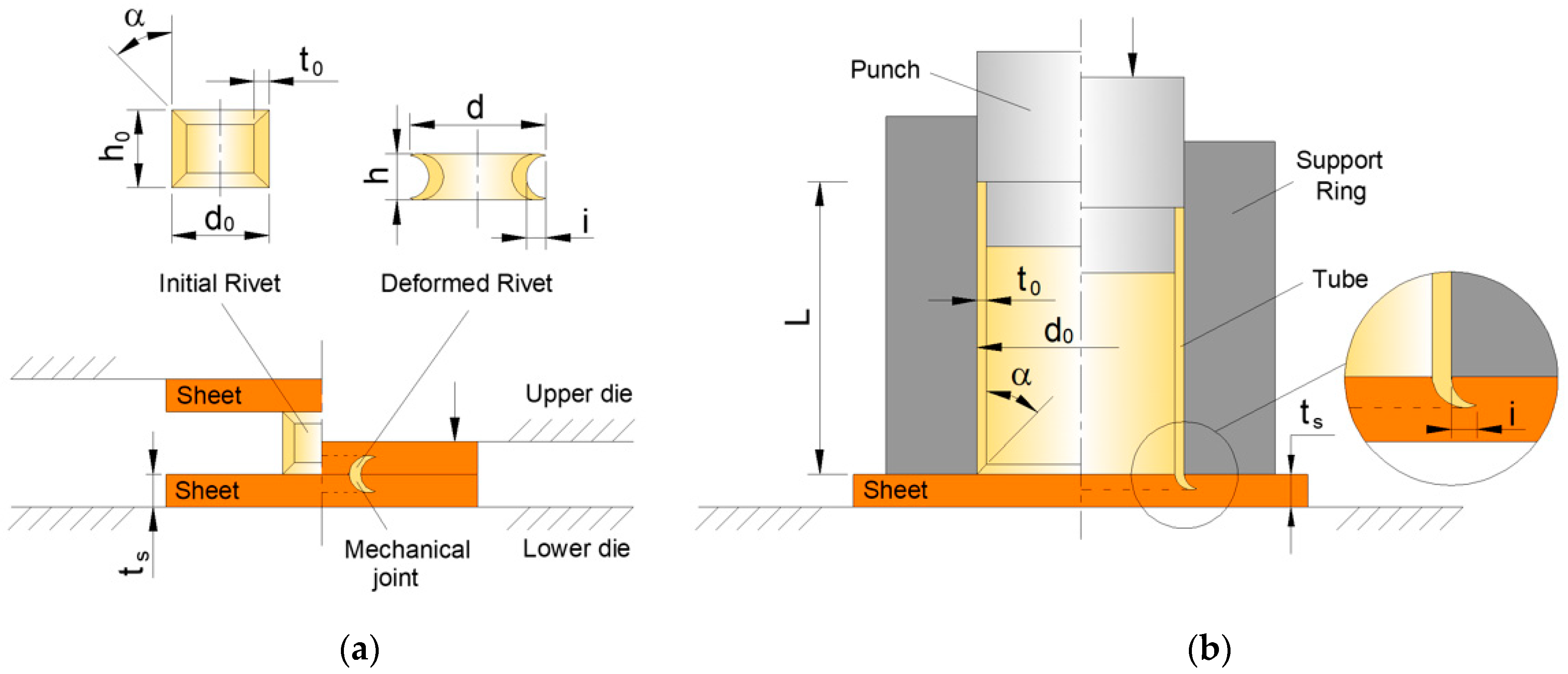
Figure 1. Schematic representation of (a) the DS-SPR process and (b) the SPR-TS configuration, showing both initial and final stages. Key rivet and sheet parameters are also indicated.
Jmmp 09 00344 g001
Figure 2. (a) Schematic of the tubular rivet configurations with varying numbers of semi-longitudinal rectangular openings and (b) corresponding photograph showing rivets with 0, 2, 4, and 8 openings (left to right).
Jmmp 09 00344 g002
Figure 3. Experimental setups for destructive testing: (a) shear test configuration and (b) torsion test configuration using the GUNT WP510 machine.
Jmmp 09 00344 g003
Figure 4. Photograph of torsion test specimens machined into hexagonal profiles and the corresponding torsion head used for testing.
Jmmp 09 00344 g004
Figure 5. Cross-sectional view of a rivet with two openings at each end, highlighting the undercut region and comparing areas with and without openings.
Jmmp 09 00344 g005
Figure 6. Force–displacement curves for joints produced with rivets having different numbers of longitudinal rectangular openings. Inset shows deformation behavior for the rivet with eight openings.
Jmmp 09 00344 g006
Figure 7. Force—displacement curves from destructive shear tests for rivets with varying numbers of longitudinal openings.
Jmmp 09 00344 g007
Figure 8. Post-test specimens from destructive shear tests: (a) 0 openings, (b) 2 openings, (c) 4 openings, and (d) 8 openings.
Jmmp 09 00344 g008
Figure 9. Force–displacement curves from destructive torsion tests for different rivet configurations, with inset showing failed specimens.
Jmmp 09 00344 g009
Figure 10. Schematic of the tool system used to join the functional rivet element to the sheet panel, protecting the threaded section during deformation. The load direction is represented by the arrow.
Jmmp 09 00344 g010
Figure 11. Functional rivet element: (a) preform with four openings and threaded end, (b) final joint after DS-SPR, and (c) cross-section showing undercut and nut engagement.
Jmmp 09 00344 g011
Figure 12. Force–displacement curves for the joining process (left vertical axis) and destructive shear test (right vertical axis) of the functional riveted element.
Jmmp 09 00344 g012
Table 1. Material designations and corresponding flow curves derived from Ludwik–Holomon power-law hardening model.
MaterialEquation
Stainless steel AISI 304 σ = 1270.5 ε 0.44
Aluminum AA5754-H111 σ = 329.3 ε 0.23
Table 2. Experimental work plan outlining the stages and configurations tested for rivet optimization and functional element evaluation.
Determination of the Optimal Number of Semi-Longitudinal Rectangular Openings
ItemQuantity
Openings0; 2; 4; 8
Sheets2
Rivets 1
Performance assessment of the optimal functional rivet element
ItemQuantity
Openings4
Sheets1
Rivets 1
Disclaimer/Publisher’s Note: The statements, opinions and data contained in all publications are solely those of the individual author(s) and contributor(s) and not of MDPI and/or the editor(s). MDPI and/or the editor(s) disclaim responsibility for any injury to people or property resulting from any ideas, methods, instructions or products referred to in the content.