
A Review of Modeling, Simulation, and Process Qualification of Additively Manufactured Metal Components via the Laser Powder Bed Fusion Method

 , , and
Abstract
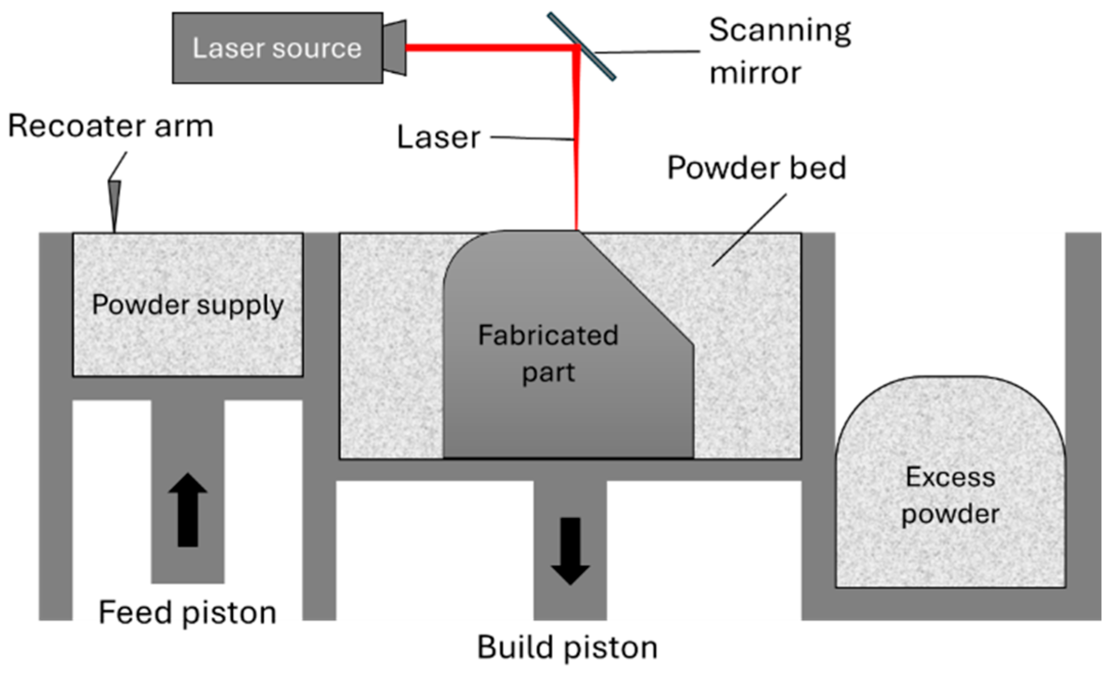
1. Introduction
- Processing: laser power, laser spot size, scan velocity, scan strategy, hatching space.
- Material: alloy powder, powder size distribution, packing density, layer thickness, build plate temperature.
- Chamber environment: build volume, inert gas, gas flow speed, chamber temperature.
2. Physical Phenomena in the LPBF Process
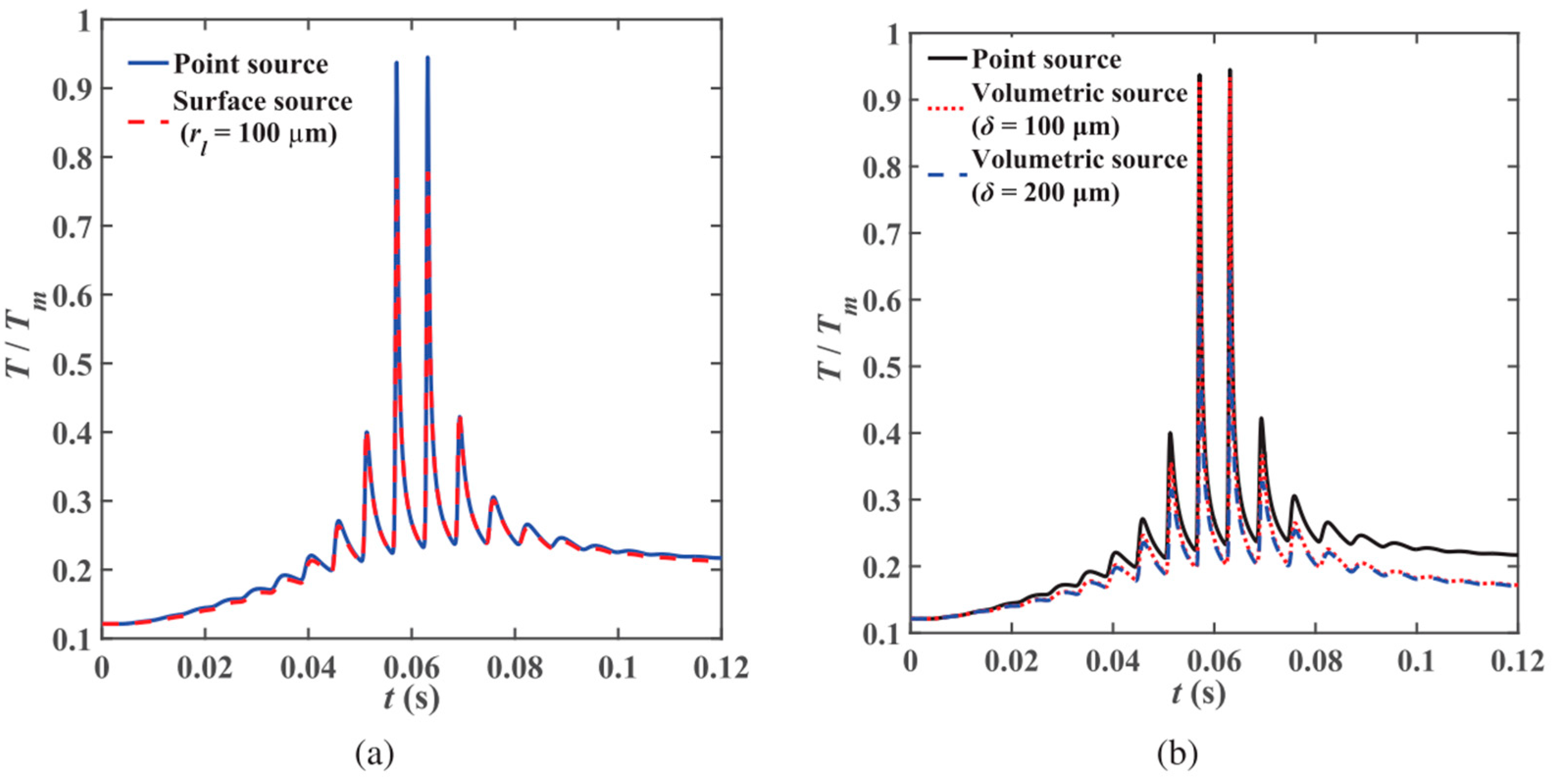
2.1. Heat Source Models
2.2. Physical Phenomena at the Melt Pool Scale
2.3. Physical Phenomena at the Part Scale
3. Part Scale Modeling and Simulation Methods
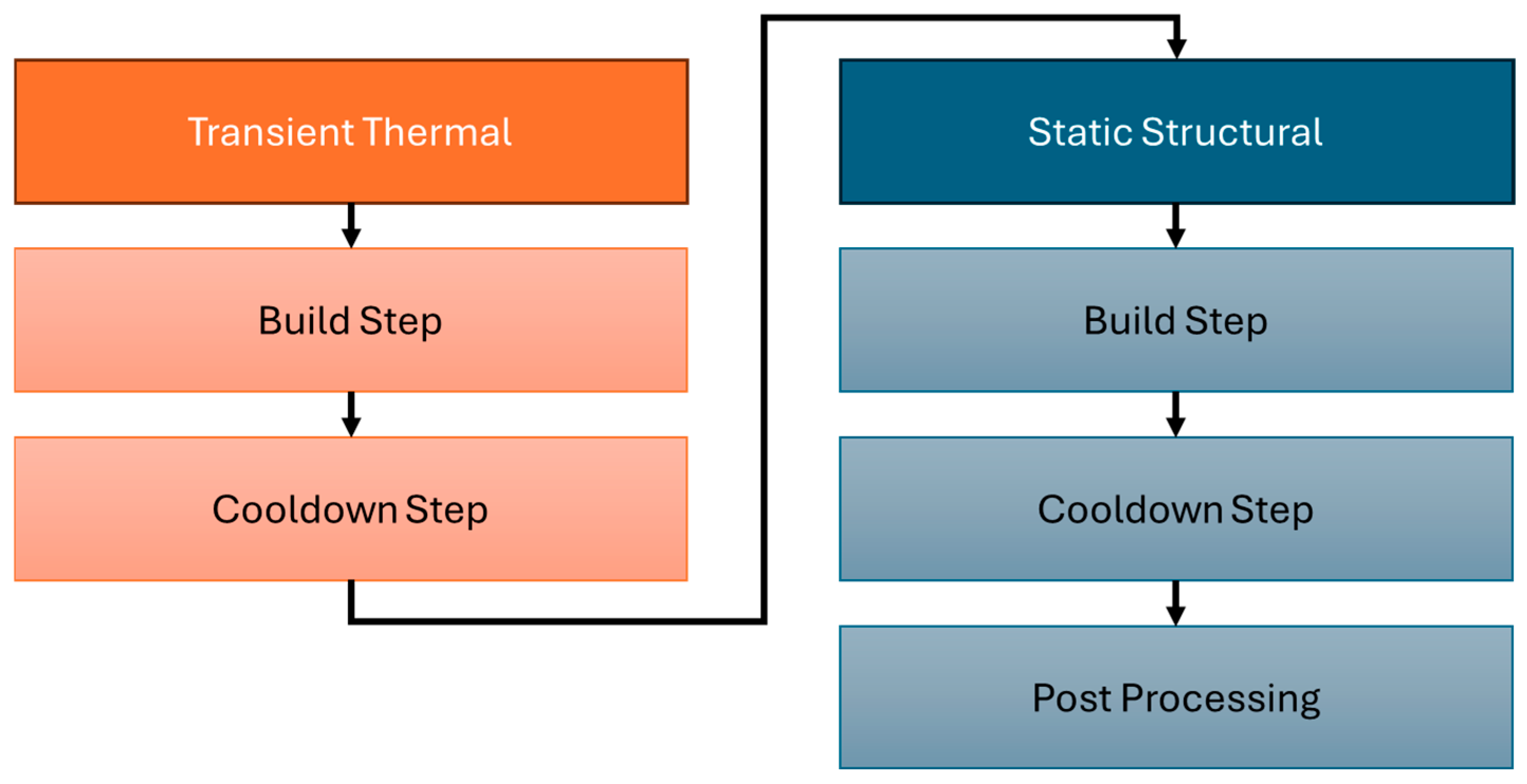
3.1. Coupled Thermomechanical Models
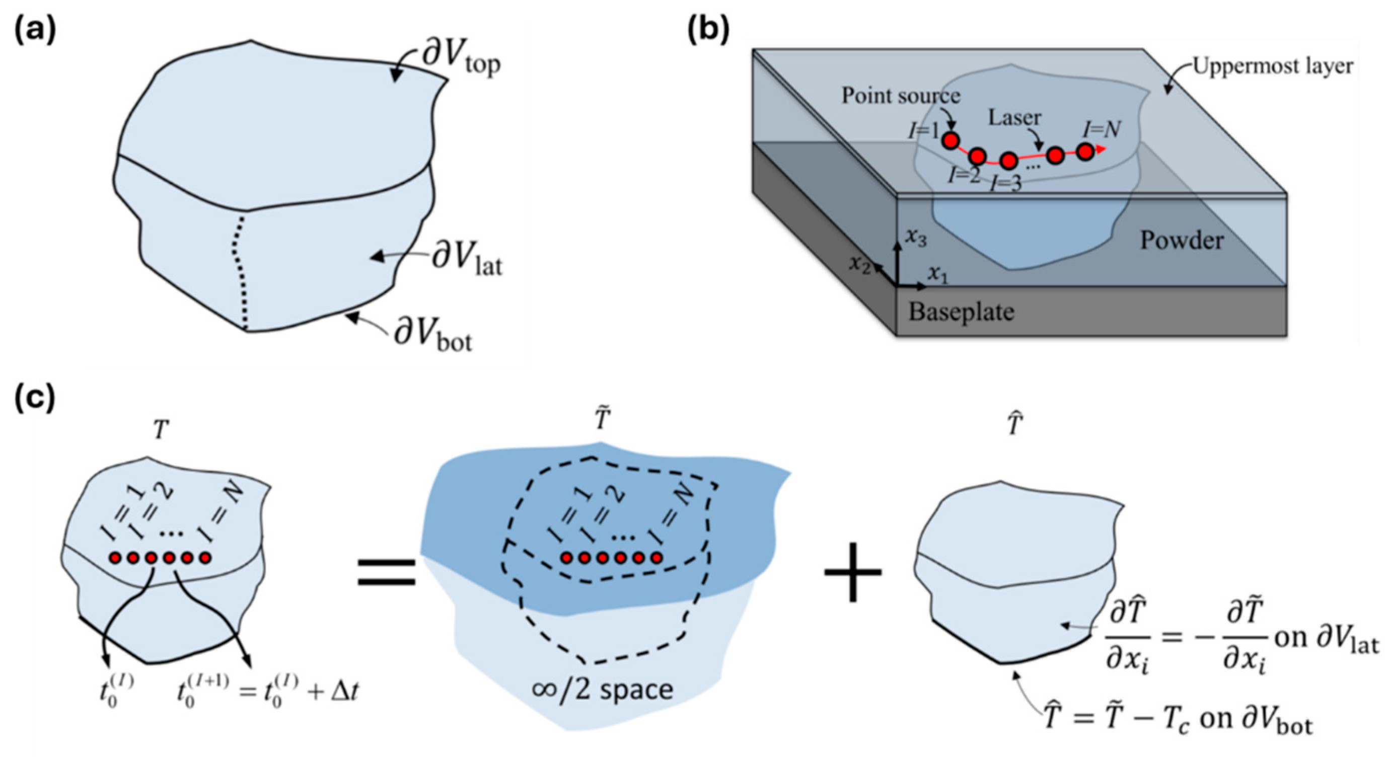
3.1.1. Semi-Analytical Methods
3.1.2. The Flash Heating Method
3.1.3. The Agglomerated Heating Method
3.2. Decoupled Thermomechanical Methods
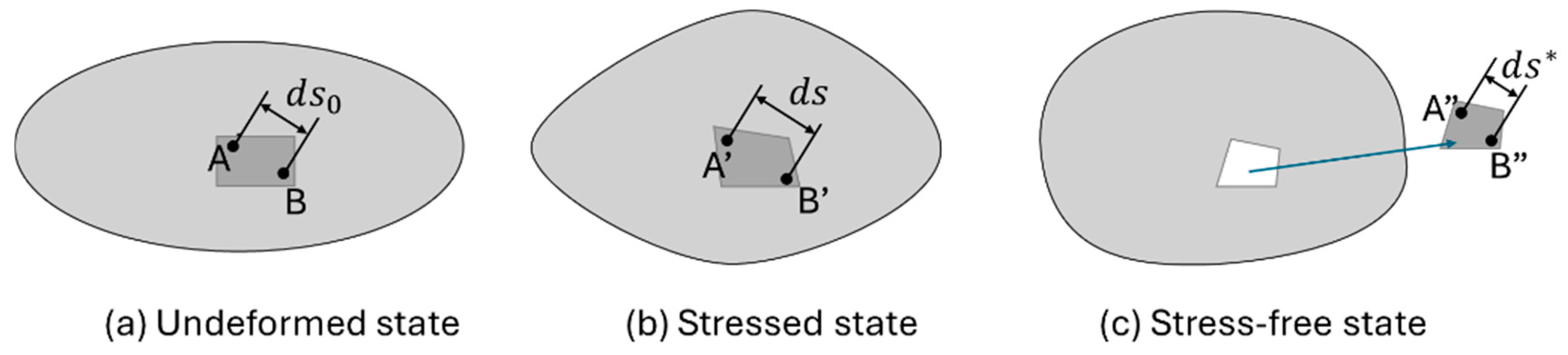
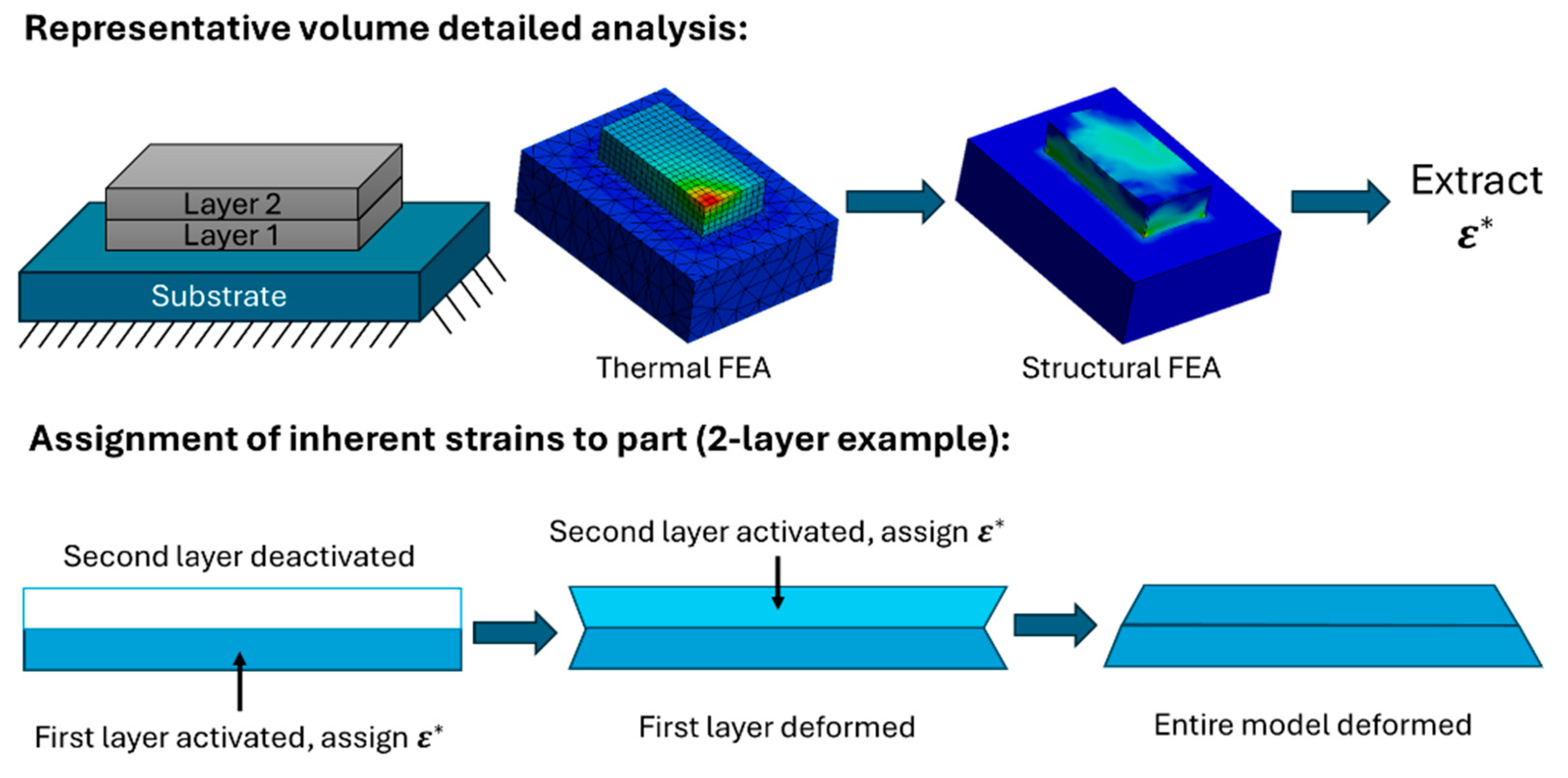
3.2.1. The Inherent Strain Theory
3.2.2. The Modified Inherent Strain Method
3.2.3. Updates in the Modified Inherent Strain Methods
4. Modeling Software for Metal AM Processes
4.1. Part Scale LPBF Modeling and Simulation Using FEA
4.2. Melt Pool Scale Modeling and Simulation Using CFD
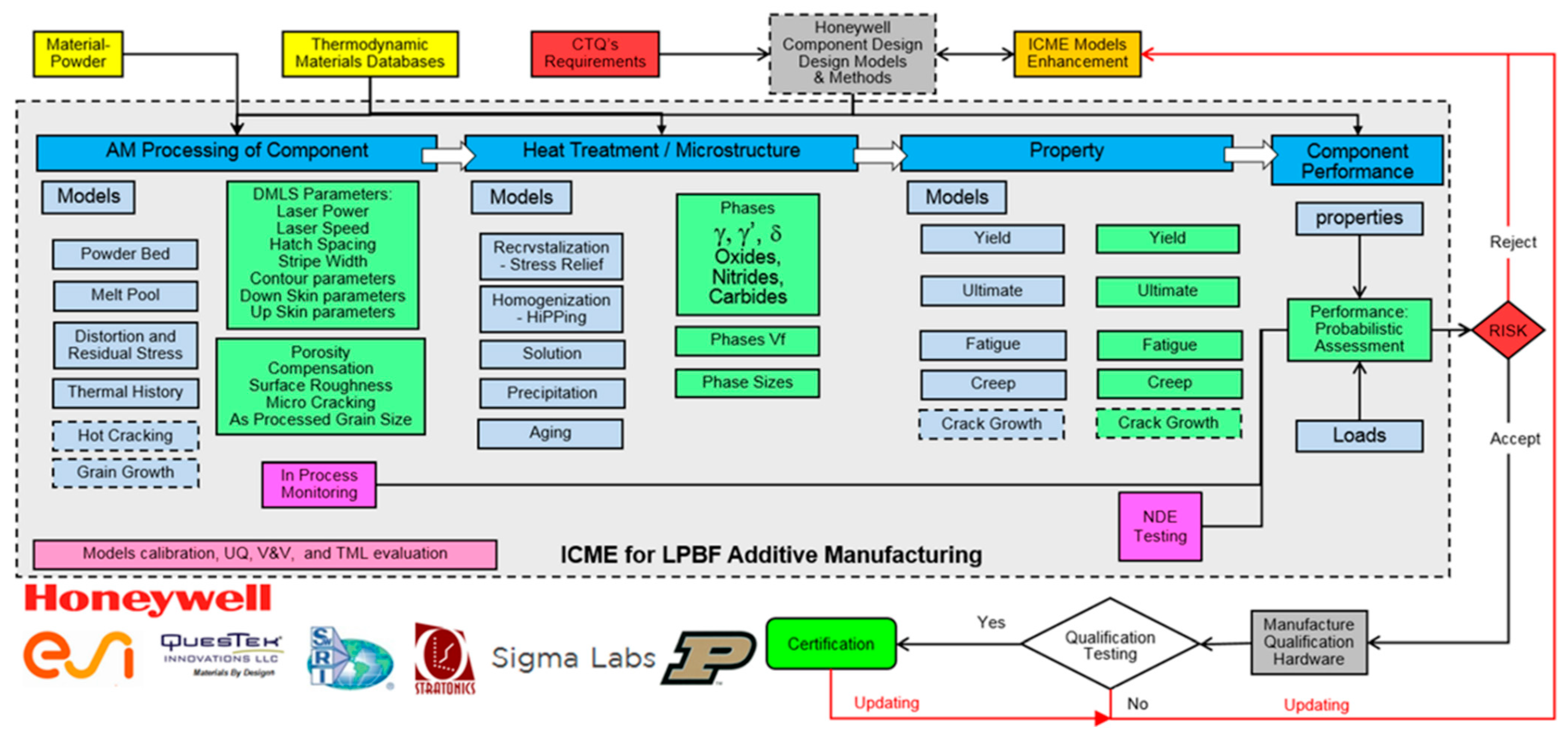
5. Qualification Processes of LPBF Components

| Specification | Title/Scope |
|---|---|
| ISO/ASTM 52900 | Additive manufacturing—General principles—Fundamentals and vocabulary |
| ISO/ASTM 52901 | Requirements for purchased AM parts |
| ISO/ASTM 52902 | Additive manufacturing—Test artifacts—Geometric capability assessment of additive manufacturing systems |
| ISO/ASTM 52904 | Practice for metal powder bed fusion process to meet critical applications |
| ISO/ASTM 52905-EB | Non-destructive testing and evaluation—Defect detection in parts |
| ISO/ASTM 52908-23 | Post-processing, inspection and testing of parts produced by powder bed fusion |
| ISO/ASTM 52920-23 | Requirements for industrial additive manufacturing processes and production sites |
| ISO/ASTM 52930-21 | Installation, operation and performance (IQ/OQ/PQ) of PBF-LB equipment |
| ISO/ASTM 52941-210 | Acceptance tests for laser metal powder-bed fusion machines for metallic materials for aerospace application |
| ISO/ASTM 52942-20 | Qualifying machine operators of laser metal powder bed fusion machines and equipment used in aerospace applications |
| ISO/ASTM 52950-21 | Additive manufacturing—General principles—Overview of data processing |
| ASTM F3530-22 | Post-Processing for Metal PBF-LB |
| ASTM F3572-22 | Part Classifications for Additive Manufactured Parts Used in Aviation |
| ASTM F3592-23 | Standard Guide for Additive Manufacturing of Metals—Powder Bed Fusion—Guidelines for Feedstock Re-use and Sampling Strategies |
| ASTM F3626-23 | Accelerated Build Quality Assurance for Laser Beam Powder Bed Fusion (PBF-LB) |
| SAE/AMS 7003 | Laser Powder Bed Fusion Process |
| SAE/AMS 7032 | Machine Qualification for Fusion-Based Metal Additive Manufacturing |
| SAE/AMS 7002A | Process Requirements for Production of Metal Powder Feedstock for Use in Additive Manufacturing of Aerospace Parts |
| AWS D20.1 | Specification for Fabrication of Metal Components Using Additive Manufacturing |
| SAE/AIR 7352 | Additively Manufactured Component Substantiation |
| DIN 65123 | Aerospace series—Methods for inspection of metallic components, produced with additive powder bed fusion processes |
| DIN 65124 | Aerospace series—Technical specifications for additive manufacturing of metallic materials with the powder bed process |
6. Discussion
7. Conclusions
- To address issues in understanding physical phenomena in the LPBF process, a focus on critical component features and corresponding processing parameters can lead to an enhanced understanding of the resulting properties of components.
- To improve capabilities in current modeling and simulation methods, future research should be focused on enabling high-fidelity LPBF models through high-performance computing to reduce computation time and obtain reliable results.
- To adopt the LPBF process as a reliable manufacturing method, an investigation of a qualification framework utilizing a cost-effective virtual integrated tool environment should be assessed to evaluate capabilities in producing accurate and reliable components.
Author Contributions
Funding
Data Availability Statement
Acknowledgments
Conflicts of Interest
References
- Langnau, L. US Air Force and GE Reach First Metal Additive Technology Milestone with Sump Cover for F110 Engine. Available online: https://www.engineering.com/us-air-force-and-ge-reach-first-metal-additive-technology-milestone-with-sump-cover-for-f110-engine/ (accessed on 1 September 2024).
- Kennedy, R. Outside the Box: How GE Aviation Entered the Brave New World of Additive Manufacturing. Available online: https://www.geaerospace.com/news/articles/100-year-anniversary-manufacturing-technology/outside-box-how-ge-aviation-entered-brave (accessed on 1 September 2024).
- Sames, W.J.; List, F.A.; Pannala, S.; Dehoff, R.R.; Babu, S.S. The metallurgy and processing science of metal additive manufacturing. Int. Mater. Rev. 2016, 61, 315–360. [Google Scholar] [CrossRef]
- Blakey-Milner, B.; Gradl, P.; Snedden, G.; Brooks, M.; Pitot, J.; Lopez, E.; Leary, M.; Berto, F.; du Plessis, A. Metal additive manufacturing in aerospace: A review. Mater. Des. 2021, 209, 110008. [Google Scholar] [CrossRef]
- Smith, J.; Xiong, W.; Yan, W.; Lin, S.; Cheng, P.; Kafka, O.L.; Wagner, G.J.; Cao, J.; Liu, W.K. Linking process, structure, property, and performance for metal-based additive manufacturing: Computational approaches with experimental support. Comput. Mech. 2016, 57, 583–610. [Google Scholar] [CrossRef]
- Joshi, S.; Martukanitz, R.P.; Nassar, A.R.; Michaleris, P. Additive Manufacturing with Metals; Springer Nature: Cham, Switzeland, 2023. [Google Scholar]
- Bergmueller, S.; Gerhold, L.; Fuchs, L.; Kaserer, L.; Leichtfried, G. Systematic approach to process parameter optimization for laser powder bed fusion of low-alloy steel based on melting modes. Int. J. Adv. Manuf. Technol. 2023, 126, 4385–4398. [Google Scholar] [CrossRef]
- Li, C.; Liu, J.F.; Guo, Y.B. Prediction of Residual Stress and Part Distortion in Selective Laser Melting. Procedia CIRP 2016, 45, 171–174. [Google Scholar] [CrossRef]
- Ki, H.; Mazumder, J.; Mohanty, P.S. Modeling of laser keyhole welding: Part I. mathematical modeling, numerical methodology, role of recoil pressure, multiple reflections, and free surface evolution. Metall. Mater. Trans. A 2002, 33, 1817–1830. [Google Scholar] [CrossRef]
- Hagenlocher, C.; O’Toole, P.; Xu, W.; Brandt, M.; Easton, M.; Molotnikov, A. Analytical modelling of heat accumulation in laser based additive manufacturing processes of metals. Addit. Manuf. 2022, 60, 103263. [Google Scholar] [CrossRef]
- Gouge, M.; Michaleris, P. Thermo-Mechanical Modeling of Additive Manufacturing; Gouge, M., Michaleris, P., Eds.; Elsevier: Amsterdam, The Netherlands, 2018. [Google Scholar]
- Gradl, P.; Tinker, D.C.; Park, A.; Mireles, O.R.; Garcia, M.; Wilkerson, R.; McKinney, C. Robust Metal Additive Manufacturing Process Selection and Development for Aerospace Components. J. Mater. Eng. Perform. 2022, 31, 6013–6044. [Google Scholar] [CrossRef]
- Chen, Z.; Han, C.; Gao, M.; Kandukuri, S.Y.; Zhou, K. A review on qualification and certification for metal additive manufacturing. Virtual Phys. Prototyp. 2021, 17, 382–405. [Google Scholar] [CrossRef]
- DebRoy, T.; Wei, H.L.; Zuback, J.S.; Mukherjee, T.; Elmer, J.W.; Milewski, J.O.; Beese, A.M.; Wilson-Heid, A.; De, A.; Zhang, W. Additive manufacturing of metallic components—Process, structure and properties. Prog. Mater. Sci. 2018, 92, 112–224. [Google Scholar] [CrossRef]
- Wei, H.L.; Mukherjee, T.; Zhang, W.; Zuback, J.S.; Knapp, G.L.; De, A.; DebRoy, T. Mechanistic models for additive manufacturing of metallic components. Prog. Mater. Sci. 2021, 116, 100703. [Google Scholar] [CrossRef]
- Milewski, J.O. Additive Manufacturing of Metals: From Fundamental Technology to Rocket Nozzles, Medical Implants, and Custom Jewelry; Springer: London, UK, 2017. [Google Scholar]
- Bevans, B.; Barrett, C.; Spears, T.; Gaikwad, A.; Riensche, A.; Smoqi, Z.; Halliday, H.; Rao, P.H.L.D. Heterogeneous sensor data fusion for multiscale, shape agnostic flaw detection in laser powder bed fusion additive manufacturing. Virtual Phys. Prototyp. 2023, 18, 2196266. [Google Scholar] [CrossRef]
- Sanaei, N.; Fatemi, A. Defects in additive manufactured metals and their effect on fatigue performance: A state-of-the-art review. Prog. Mater. Sci. 2021, 117, 100724. [Google Scholar] [CrossRef]
- Singla, A.K.; Banerjee, M.; Sharma, A.; Singh, J.; Bansal, A.; Gupta, M.K.; Khanna, N.; Shahi, A.S.; Goyal, D.K. Selective laser melting of Ti6Al4V alloy: Process parameters, defects and post-treatments. J. Manuf. Process. 2021, 64, 161–187. [Google Scholar] [CrossRef]
- Wang, L.; Yu, Y.; Hu, D.; Yan, W. Multiscale modeling applied to additive manufacturing. In Fundamentals of Multiscale Modeling of Structural Materials; Elseiver: Amsterdam, The Netherlands, 2023; pp. 333–388. [Google Scholar]
- Sun, C.; Wang, Y.; McMurtrey, M.D.; Jerred, N.D.; Liou, F.; Li, J. Additive manufacturing for energy: A review. Appl. Energy 2021, 28, 2116041. [Google Scholar] [CrossRef]
- Sharma, S.; Joshi, S.S.; Pantawane, M.V.; Radhakrishnan, M.; Mazumder, S.; Dahotre, N.B. Multiphysics multi-scale computational framework for linking process–structure–property relationships in metal additive manufacturing: A critical review. Int. Mater. Rev. 2023, 68, 1–67. [Google Scholar] [CrossRef]
- Zaeh, M.F.; Branner, G. Investigations on residual stresses and deformations in selective laser melting. Prod. Eng. 2009, 4, 35–45. [Google Scholar] [CrossRef]
- Papadakis, L.; Branner, G.; Schober, A.; Richter, K.H.; Uihlein, T. Numerical Modeling of Heat Effects during Thermal Manufacturing of Aero Engine Components. In Proceedings of the World Congress on Engineering, London, UK, 4–6 July 2012. [Google Scholar]
- Berry, J.; Perron, A.; Fattebert, J.-L.; Roehling, J.D.; Vrancken, B.; Roehling, T.T.; Rosas, D.L.; Turner, J.A.; Khairallah, S.A.; McKeown, J.T.; et al. Toward multiscale simulations of tailored microstructure formation in metal additive manufacturing. Mater. Today 2021, 51, 65–86. [Google Scholar] [CrossRef]
- Papadakis, L. Modeling and simulation of additive manufacturing processes with metallic powders—Potentials and limitations demonstrated on application examples. In Additive Manufacturing; Elseiver: Amsterdam, The Netherlands, 2021; pp. 685–721. [Google Scholar]
- Markl, M.; Körner, C. Multiscale Modeling of Powder Bed–Based Additive Manufacturing. Annu. Rev. Mater. Res. 2016, 46, 93–123. [Google Scholar] [CrossRef]
- Promoppatum, P.; Uthaisangsuk, V. Part scale estimation of residual stress development in laser powder bed fusion additive manufacturing of Inconel 718. Finite Elem. Anal. Des. 2021, 189, 103528. [Google Scholar] [CrossRef]
- Francois, M.M.; Sun, A.; King, W.E.; Henson, N.; Tourret, D.; Bronkhorst, C.; Carlson, N.N.; Newman, C.; Haut, T.; Bakosi, J.; et al. Modeling of Additive Manufacturing Processes for Metals: Challenges and Opportunities. Curr. Opin. Solid State Mater. Sci. 2017, 21, 198–206. [Google Scholar] [CrossRef]
- Ahmed, N.; Barsoum, I.; Haidemenopoulos, G.; Al-Rub, R.K.A. Process parameter selection and optimization of laser powder bed fusion for 316L stainless steel: A review. J. Manuf. Process. 2022, 75, 415–434. [Google Scholar] [CrossRef]
- Yang, Y.; Knol, M.F.; van Keulen, F.; Ayas, C. A semi-analytical thermal modelling approach for selective laser melting. Addit. Manuf. 2018, 21, 284–297. [Google Scholar] [CrossRef]
- Yang, Y.; Ayas, C. Point, surface and volumetric heat sources in the thermal modelling of selective laser melting. Conf. Proc. 2017, 1896, 040006. [Google Scholar]
- Darmadi, D.B.; Norrish, J.; Tieu, A.K. Analytic and Finite Element Solutions for Temperature Profiles in Welding using Varied Heat Source Models. Int. Rev. Mech. Eng. 2011, 11, 8. [Google Scholar]
- Rosenthal, D. The Theory of Moving Sources of Heat and Its Application to Metal Treatments. Trans. Am. Soc. Mech. Eng. 1946, 68, 849–865. [Google Scholar] [CrossRef]
- Goldak, J.A.; Akhlaghi, M. Computational Welding Mechanics; Springer: London, UK, 2005. [Google Scholar]
- Huang, Y. Comprehensive Analytical Modeling of Laser Powder Bed Fed Additive Manufacuting Processes. Ph.D. Thesis, University of Waterloo, Waterloo, ON, Canada, 2019. [Google Scholar]
- Yang, J.; Han, J.; Yu, H.; Yin, J.; Gao, M.; Wang, Z.; Zeng, X. Role of molten pool mode on formability, microstructure and mechanical properties of selective laser melted Ti-6Al-4V alloy. Mater. Des. 2016, 110, 558–570. [Google Scholar] [CrossRef]
- Megahed, M.; Mindt, H.-W.; Willems, J.; Dionne, P.; Jacquemetton, L.; Craig, J.; Ranade, P.; Peralta, A. LPBF Right the First Time—The Right Mix Between Modeling and Experiments. Integr. Mater. Manuf. Innov. 2019, 8, 194–216. [Google Scholar] [CrossRef]
- King, W.E.; Anderson, A.T.; Ferencz, R.M.; Hodge, N.E.; Kamath, C.; Khairallah, S.A.; Rubenchik, A.M. Laser powder bed fusion additive manufacturing of metals; physics, computational, and materials challenges. Appl. Phys. Rev. 2015, 2, 041304. [Google Scholar] [CrossRef]
- Cook, P.S.; Murphy, A.B. Simulation of melt pool behaviour during additive manufacturing: Underlying physics and progress. Addit. Manuf. 2020, 31, 100909. [Google Scholar] [CrossRef]
- Zhang, Y.; Chen, Q.; Guillemot, G.; Gandin, C.-A.; Bellet, M. Numerical modelling of fluid and solid thermomechanics in additive manufacturing by powder-bed fusion: Continuum and level set formulation applied to track- and part-scale simulations. Comptes Rendus Mécanique 2018, 346, 1055–1071. [Google Scholar] [CrossRef]
- Fabbro, R. Physical mechanisms controlling keyhole and melt pool dynamics during laser welding. In Advances in Laser Materials Processing; Elseiver: Amsterdam, The Netherlands, 2010; pp. 211–241. [Google Scholar]
- Qi, T.; Zhu, H.; Zhang, H.; Yin, J.; Ke, L.; Zeng, X. Selective laser melting of Al7050 powder: Melting mode transition and comparison of the characteristics between the keyhole and conduction mode. Mater. Des. 2017, 135, 257–266. [Google Scholar] [CrossRef]
- Lei, Z.; Bi, J.; Chen, Y.; Chen, X.; Qin, X.; Tian, Z. Effect of energy density on formability, microstructure and micro-hardness of selective laser melted Sc- and Zr- modified 7075 aluminum alloy. Powder Technol. 2019, 356, 594–606. [Google Scholar] [CrossRef]
- Gaikwad, A.; Giera, B.; Guss, G.M.; Forien, J.-B.; Matthews, M.J.; Rao, P. Heterogeneous sensing and scientific machine learning for quality assurance in laser powder bed fusion—A single-track study. Addit. Manuf. 2020, 36, 101659. [Google Scholar] [CrossRef]
- King, W.E.; Barth, H.D.; Castillo, V.M.; Gallegos, G.F.; Gibbs, J.W.; Hahn, D.E.; Kamath, C.; Rubenchik, A.M. Observation of keyhole-mode laser melting in laser powder-bed fusion additive manufacturing. J. Mater. Process. Technol. 2014, 214, 2915–2925. [Google Scholar] [CrossRef]
- Semak, V.; Matsunawa, A. The role of recoil pressure in energy balance during laser materials processing. J. Phys. D Appl. Phys. 1997, 30, 18. [Google Scholar] [CrossRef]
- Wu, Y.-C.; San, C.-H.; Chang, C.-H.; Lin, H.-J.; Marwan, R.; Baba, S.; Hwang, W.-S. Numerical modeling of melt-pool behavior in selective laser melting with random powder distribution and experimental validation. J. Mater. Process. Technol. 2018, 254, 72–78. [Google Scholar] [CrossRef]
- Leung, C.L.A.; Marussi, S.; Atwood, R.C.; Towrie, M.; Withers, P.J.; Lee, P.D. In situ X-ray imaging of defect and molten pool dynamics in laser additive manufacturing. Nat. Commun. 2018, 9, 1355. [Google Scholar] [CrossRef] [PubMed]
- Maamoun, A.H.; Xue, Y.F.; Elbestawi, M.A.; Veldhuis, S.C. Effect of Selective Laser Melting Process Parameters on the Quality of Al Alloy Parts: Powder Characterization, Density, Surface Roughness, and Dimensional Accuracy. Materials 2018, 11, 2343. [Google Scholar] [CrossRef]
- Maamoun, A.H.; Xue, Y.F.; Elbestawi, M.A.; Veldhuis, S.C. The Effect of Selective Laser Melting Process Parameters on the Microstructure and Mechanical Properties of Al6061 and AlSi10Mg Alloys. Materials 2018, 12, 10012. [Google Scholar] [CrossRef] [PubMed]
- Radaj, D. Heat Effects of Welding: Temperature Field, Residual Stress, Distortion; Springer: London, UK, 1992. [Google Scholar]
- Williams, R.J.; Piglione, A.; Rønneberg, T.; Jones, C.; Pham, M.-S.; Davies, C.M.; Hooper, P.A. In situ thermography for laser powder bed fusion: Effects of layer temperature on porosity, microstructure and mechanical properties. Addit. Manuf. 2019, 30, 100880. [Google Scholar] [CrossRef]
- Hooper, P.A. Melt pool temperature and cooling rates in laser powder bed fusion. Addit. Manuf. 2018, 22, 548–559. [Google Scholar] [CrossRef]
- Arısoy, Y.M.; Criales, L.E.; Özel, T. Modeling and simulation of thermal field and solidification in laser powder bed fusion of nickel alloy IN625. Opt. Laser Technol. 2019, 109, 278–292. [Google Scholar] [CrossRef]
- Bayat, M.; Dong, W.; Thorborg, J.; To, A.C.; Hattel, J.H. A review of multi-scale and multi-physics simulations of metal additive manufacturing processes with focus on modeling strategies. Addit. Manuf. 2021, 47, 102278. [Google Scholar] [CrossRef]
- Parry, L.; Ashcroft, I.A.; Wildman, R.D. Understanding the effect of laser scan strategy on residual stress in selective laser melting through thermo-mechanical simulation. Addit. Manuf. 2016, 12, 1–15. [Google Scholar] [CrossRef]
- Martukanitz, R.; Michaleris, P.; Palmer, T.; DebRoy, T.; Liu, Z.-K.; Otis, R.; Heo, T.W.; Chen, L.-Q. Toward an integrated computational system for describing the additive manufacturing process for metallic materials. Addit. Manuf. 2014, 1–4, 52–63. [Google Scholar] [CrossRef]
- Yan, W.; Lian, Y.; Yu, C.; Kafka, O.L.; Liu, Z.; Liu, W.K.; Wagner, G.J. An integrated process–structure–property modeling framework for additive manufacturing. Comput. Methods Appl. Mech. Eng. 2018, 339, 184–204. [Google Scholar] [CrossRef]
- Zhang, Y.; Zhang, J. Modeling of solidification microstructure evolution in laser powder bed fusion fabricated 316L stainless steel using combined computational fluid dynamics and cellular automata. Addit. Manuf. 2019, 28, 750–765. [Google Scholar] [CrossRef]
- Lian, Y.; Gan, Z.; Yu, C.; Kats, D.; Liu, W.K.; Wagner, G.J. A cellular automaton finite volume method for microstructure evolution during additive manufacturing. Mater. Des. 2019, 169, 107672. [Google Scholar] [CrossRef]
- Elangeswaran, C.; Cutolo, A.; Gallas, S.; Dinh, T.D.; Lammens, N.; Erdelyi, H.; Schulz, M.; Muralidharan, G.K.; Thijs, L.; Craeghs, T.; et al. Predicting fatigue life of metal LPBF components by combining a large fatigue database for different sample conditions with novel simulation strategies. Addit. Manuf. 2022, 50, 102570. [Google Scholar] [CrossRef]
- Oliveira, J.P.; Santos, T.G.; Miranda, R.M. Revisiting fundamental welding concepts to improve additive manufacturing: From theory to practice. Prog. Mater. Sci. 2020, 107, 100590. [Google Scholar] [CrossRef]
- Riensche, A.R.; Bevans, B.D.; King, G.; Krishnan, A.; Cole, K.D.; Rao, P. Predicting meltpool depth and primary dendritic arm spacing in laser powder bed fusion additive manufacturing using physics-based machine learning. Mater. Des. 2024, 237, 112540. [Google Scholar] [CrossRef]
- Promoppatum, P.; Yao, S.-C.; Pistorius, P.C.; Rollett, A.D. A Comprehensive Comparison of the Analytical and Numerical Prediction of the Thermal History and Solidification Microstructure of Inconel 718 Products Made by Laser Powder-Bed Fusion. Engineering 2017, 3, 685–694. [Google Scholar] [CrossRef]
- Cole, K.D.; Riensche, A.; Rao, P.K. Discrete Green’s functions and spectral graph theory for computationally efficient thermal modeling. Int. J. Heat Mass Transf. 2022, 183, 122112. [Google Scholar] [CrossRef]
- Bayat, M.; Klingaa, C.G.; Mohanty, S.; De Baere, D.; Thorborg, J.; Tiedje, N.S.; Hattel, J.H. Part-scale thermo-mechanical modelling of distortions in Laser Powder Bed Fusion—Analysis of the sequential flash heating method with experimental validation. Addit. Manuf. 2020, 36, 101508. [Google Scholar] [CrossRef]
- Moran, T.P.; Warner, D.H.; Phan, N. Scan-by-scan part-scale thermal modelling for defect prediction in metal additive manufacturing. Addit. Manuf. 2021, 37, 101667. [Google Scholar] [CrossRef]
- Moran, T.P.; Li, P.; Warner, D.H.; Phan, N. Utility of superposition-based finite element approach for part-scale thermal simulation in additive manufacturing. Addit. Manuf. 2018, 21, 215–219. [Google Scholar] [CrossRef]
- Holman, J. Heat Transfer, 10th ed.; McGraw Hill: New York City, NY, USA, 2010. [Google Scholar]
- Gouge, M.; Denlinger, E.; Irwin, J.; Li, C.; Michaleris, P. Experimental validation of thermo-mechanical part-scale modeling for laser powder bed fusion processes. Addit. Manuf. 2019, 29, 100771. [Google Scholar] [CrossRef]
- Zhang, W.; Tong, M.; Harrison, N.M. Resolution, energy and time dependency on layer scaling in finite element modelling of laser beam powder bed fusion additive manufacturing. Addit. Manuf. 2019, 28, 610–620. [Google Scholar] [CrossRef]
- Williams, R.J.; Davies, C.M.; Hooper, P.A. A pragmatic part scale model for residual stress and distortion prediction in powder bed fusion. Addit. Manuf. 2018, 22, 416–425. [Google Scholar] [CrossRef]
- Ganeriwala, R.K.; Strantza, M.; King, W.E.; Clausen, B.; Phan, T.Q.; Levine, L.E.; Brown, D.W.; Hodge, N.E. Evaluation of a thermomechanical model for prediction of residual stress during laser powder bed fusion of Ti-6Al-4V. Addit. Manuf. 2019, 27, 489–502. [Google Scholar] [CrossRef]
- Hodge, N.E.; Ferencz, R.M.; Vignes, R.M. Experimental comparison of residual stresses for a thermomechanical model for the simulation of selective laser melting. Addit. Manuf. 2016, 12, 159–168. [Google Scholar] [CrossRef]
- Liang, X.; Cheng, L.; Chen, Q.; Yang, Q.; To, A.C. A modified method for estimating inherent strains from detailed process simulation for fast residual distortion prediction of single-walled structures fabricated by directed energy deposition. Addit. Manuf. 2018, 23, 471–486. [Google Scholar] [CrossRef]
- Xie, D.; Lv, F.; Yang, Y.; Shen, L.; Tian, Z.; Shuai, C.; Chen, B.; Zhao, J. A Review on Distortion and Residual Stress in Additive Manufacturing. Chin. J. Mech. Eng. Addit. Manuf. Front. 2022, 1, 100039. [Google Scholar] [CrossRef]
- Liang, X.; Chen, Q.; Cheng, L.; Hayduke, D.; To, A.C. Modified inherent strain method for efficient prediction of residual deformation in direct metal laser sintered components. Comput. Mech. 2019, 64, 1719–1733. [Google Scholar] [CrossRef]
- Ueda, Y.; Fukuda, K.; Tanigawa, M. New Measuring Method of Three Dimensional Residual Stresses Based on Theory of Inherent Strain. Trans. JWRI 1979, 8, 249–256. [Google Scholar]
- Ueda, Y.; Fukuda, K.; Kim, Y.C. New Measuring Method of Axisymmetric Three-Dimensional Residual Stresses Using Inherent Strains as Parameters. J. Eng. Mater. Technol. 1986, 108, 328–334. [Google Scholar] [CrossRef]
- Chen, Q.; Liang, X.; Hayduke, D.; Liu, J.; Cheng, L.; Oskin, J.; Whitmore, R.; To, A.C. An inherent strain based multiscale modeling framework for simulating part-scale residual deformation for direct metal laser sintering. Addit. Manuf. 2019, 28, 406–418. [Google Scholar] [CrossRef]
- Dong, W.; Liang, X.; Chen, Q.; Hinnebusch, S.; Zhou, Z.; To, A.C. A new procedure for implementing the modified inherent strain method with improved accuracy in predicting both residual stress and deformation for laser powder bed fusion. Addit. Manuf. 2021, 47, 102345. [Google Scholar] [CrossRef]
- Michaleris, P. Modeling metal deposition in heat transfer analyses of additive manufacturing processes. Finite Elem. Anal. Des. 2014, 86, 51–60. [Google Scholar] [CrossRef]
- Dong, W.; Jimenez, X.A.; To, A.C. Temperature-dependent modified inherent strain method for predicting residual stress and distortion of Ti6Al4V walls manufactured by wire-arc directed energy deposition. Addit. Manuf. 2023, 62, 103386. [Google Scholar] [CrossRef]
- Bellet, M.; Tematio, J.K.; Zhang, Y. The inherent strain method for additive manufacturing: Critical analysis and new inherent strain rate method. IOP Conf. Ser. Mater. Sci. Eng. 2023, 1281, 012001. [Google Scholar] [CrossRef]
- Bellet, M.; Keumo Tematio, J.; Zhang, Y. The inherent strain rate method for thermo-mechanical simulation of directed energy deposition additive manufacturing. Int. J. Numer. Methods Eng. 2023, 124, 4058–4074. [Google Scholar] [CrossRef]
- Doghri, I. Mechanics of Deformable Solids: Linear, Nonlinear, Analytical and Computational Aspects; Springer: London, UK, 2000. [Google Scholar]
- Badiru, A.B.; Valencia, V.V.; Liu, D. Additive Manufacturing Handbook Product Development for the Defense Industry; Badiru, A.B., Valencia, V.V., Liu, D., Eds.; CRC Press: Boca Raton, FL, USA, 2017. [Google Scholar]
- Lian, Y.; Lin, S.; Yan, W.; Liu, W.K.; Wagner, G.J. A parallelized three-dimensional cellular automaton model for grain growth during additive manufacturing. Comput. Mech. 2018, 61, 543–558. [Google Scholar] [CrossRef]
- Zinoviev, A.; Zinovieva, O.; Ploshikhin, V.; Romanova, V.; Balokhonov, R. Evolution of grain structure during laser additive manufacturing. Simulation by a cellular automata method. Mater. Des. 2016, 106, 321–329. [Google Scholar] [CrossRef]
- Guo, Z.; Zhou, J.; Yin, Y.; Shen, X.; Ji, X. Numerical Simulation of Three-Dimensional Mesoscopic Grain Evolution: Model Development, Validation, and Application to Nickel-Based Superalloys. Metals 2019, 9, 10057. [Google Scholar] [CrossRef]
- Bresson, Y.; Tongne, A.; Baili, M.; Arnaud, L. Global-to-local simulation of the thermal history in the laser powder bed fusion process based on a multiscale finite element approach. Int. J. Adv. Manuf. Technol. 2023, 127, 4727–4744. [Google Scholar] [CrossRef]
- Pal, D.; Patil, N.; Zeng, K.; Stucker, B. An Integrated Approach to Additive Manufacturing Simulations Using Physics Based, Coupled Multiscale Process Modeling. J. Manuf. Sci. Eng. 2014, 136, 061022. [Google Scholar] [CrossRef]
- O’Toole, P.I.; Patel, M.J.; Tang, C.; Gunasegaram, D.; Murphy, A.B.; Cole, I.S. Multiscale simulation of rapid solidifi cation of an aluminium–silicon alloy under additive manufacturing conditions. Addit. Manuf. 2021, 48, 102353. [Google Scholar] [CrossRef]
- Mollamahmutoglu, M.; Yilmaz, O.; Unal, R.; Gumus, B.; Tan, E. The effect of evaporation and recoil pressure on energy loss and melt pool profile in selective electron beam melting. Int. J. Adv. Manuf. Technol. 2022, 120, 4041–4050. [Google Scholar] [CrossRef]
- Ninpetch, P.; Kowitwarangkul, P.; Chalermkarnnon, P.; Promoppatum, P.; Chuchuay, P.; Rattanadecho, P. Numerical Modeling of Distortion of Ti-6Al-4V Components Manufactured Using Laser Powder Bed Fusion. Metals 2022, 12, 91484. [Google Scholar] [CrossRef]
- Mukherjee, T.; Wei, H.L.; De, A.; DebRoy, T. Heat and fluid flow in additive manufacturing—Part I: Modeling of powder bed fusion. Comput. Mater. Sci. 2018, 150, 304–313. [Google Scholar] [CrossRef]
- Liu, J.; Wen, P. Metal vaporization and its influence during laser powder bed fusion process. Mater. Des. 2022, 215, 110505. [Google Scholar] [CrossRef]
- Klassen, A.; Scharowsky, T.; Körner, C. Evaporation model for beam based additive manufacturing using free surface lattice Boltzmann methods. J. Phys. D Appl. Phys. 2014, 47, 275303. [Google Scholar] [CrossRef]
- Fish, J.; Belytschko, T. A First Course in Finite Elements; Wiley: Hoboken, NJ, USA, 2007. [Google Scholar]
- Schoinochoritis, B.; Chantzis, D.; Salonitis, K. Simulation of metallic powder bed additive manufacturing processes with the finite element method: A critical review. Proc. Inst. Mech. Eng. Part B J. Eng. Manuf. 2016, 231, 96–117. [Google Scholar] [CrossRef]
- Yang, Q.C.; Zhang, P.; Cheng, L.; Min, Z.; Chyu, M.; To, A.C. Finite element modeling and validation of thermomechanical behavior of Ti-6Al-4V in directed energy deposition additive manufacturing. Addit. Manuf. 2016, 12, 169–177. [Google Scholar] [CrossRef]
- Mayer, T.; Brandle, G.; Schonenberger, A.; Eberlein, R. Simulation and validation of residual deformations in additive manufacturing of metal parts. Heliyon 2020, 6, e03987. [Google Scholar] [CrossRef]
- ANSYS. Additive Calibration Guide; ANSYS: Canonsburg, PA, USA, 2021. [Google Scholar]
- ANSYS. ANSYS Workbench Additive Manufacturing Analysis Guide; ANSYS: Canonsburg, PA, USA, 2021. [Google Scholar]
- Weber, S.; Montero, J.; Bleckmann, M.; Paetzold, K. A Comparison of Layered Tetrahedral and Cartesian meshing in Additive Manufacturing Simulation. Procedia CIRP 2020, 91, 522–527. [Google Scholar] [CrossRef]
- Moges, T.; Ameta, G.; Witherell, P. A Review of Model Inaccuracy and Parameter Uncertainty in Laser Powder Bed Fusion Models and Simulations. J. Manuf. Sci. Eng. 2019, 141, 040801. [Google Scholar] [CrossRef] [PubMed]
- Vanini, M.; Searle, S.; Vanmeensel, K.; Vrancken, B. Avoiding heat source calibration for finite element modeling of the laser powder bed fusion process. Addit. Manuf. 2024, 92, 104369. [Google Scholar] [CrossRef]
- DebRoy, T.; David, S.A. Physical processes in fusion welding. Rev. Mod. Phys. 1995, 67, 85–112. [Google Scholar] [CrossRef]
- Manvatkar, V.; De, A.; DebRoy, T. Heat transfer and material flow during laser assisted multi-layer additive manufacturing. J. Appl. Phys. 2014, 116, 124905. [Google Scholar] [CrossRef]
- Chen, F.; Yan, W. High-fidelity modelling of thermal stress for additive manufacturing by linking thermal-fluid and mechanical models. Mater. Des. 2020, 196, 109185. [Google Scholar] [CrossRef]
- FlowScience. FLOW-3D User Manual, Release 2022R2; FlowScience: Santa Fe, NM, USA, 2022. [Google Scholar]
- Lee, Y.S.; Zhang, W. Modeling of heat transfer, fluid flow and solidification microstructure of nickel-base superalloy fabricated by laser powder bed fusion. Addit. Manuf. 2016, 12, 178–188. [Google Scholar] [CrossRef]
- Yan, W.; Ge, W.; Qian, Y.; Lin, S.; Zhou, B.; Liu, W.K.; Lin, F.; Wagner, G.J. Multi-physics modeling of single/multiple-track defect mechanisms in electron beam selective melting. Acta Mater. 2017, 134, 324–333. [Google Scholar] [CrossRef]
- Bayat, M.; Mohanty, S.; Hattel, J.H. Multiphysics modelling of lack-of-fusion voids formation and evolution in IN718 made by multi-track/multi-layer L-PBF. Int. J. Heat Mass Transf. 2019, 139, 95–114. [Google Scholar] [CrossRef]
- Bayat, M.; Thanki, A.; Mohanty, S.; Witvrouw, A.; Yang, S.; Thorborg, J.; Tiedje, N.S.; Hattel, J.H. Keyhole-induced porosities in Laser-based Powder Bed Fusion (L-PBF) of Ti6Al4V: High-fidelity modelling and experimental validation. Addit. Manuf. 2019, 30, 100835. [Google Scholar] [CrossRef]
- Li, E.; Zhou, Z.; Wang, L.; Zou, R.; Yu, A. Modelling of keyhole dynamics and melt pool flow in laser powder bed fusion process. Powder Technol. 2022, 400, 117262. [Google Scholar] [CrossRef]
- Hirt, C.; Nichols, B. Volume of Fluid (VOF) Method for the Dynamics of Free Boundaries. J. Comput. Phys. 1981, 39, 201–225. [Google Scholar] [CrossRef]
- Katopodes, N.D. Volume of Fluid Method. In Free-Surface Flow; Elseiver: Amsterdam, The Netherlands, 2019; pp. 766–802. [Google Scholar]
- Mohd Yusuf, S.; Cutler, S.; Gao, N. Review: The Impact of Metal Additive Manufacturing on the Aerospace Industry. Metals 2019, 9, 1286. [Google Scholar] [CrossRef]
- Chang, K.-H. E-Design: Computer-Aided Engineering Design, 1st ed.; Elsvier: Amsterdam, The Netherlands, 2016. [Google Scholar]
- Dordlofva, C. A Design for Qualification Framework for the Development of Additive Manufacturing Components—A Case Study from the Space Industry. Aerospace 2020, 7, 30025. [Google Scholar] [CrossRef]
- Taylor, H.C.; Garibay, E.A.; Wicker, R.B. Toward a common laser powder bed fusion qualification test artifact. Addit. Manuf. 2021, 39, 101803. [Google Scholar] [CrossRef]
- Seifi, M.; Gorelik, M.; Waller, J.; Hrabe, N.; Shamsaei, N.; Daniewicz, S.; Lewandowski, J.J. Progress Towards Metal Additive Manufacturing Standardization to Support Qualification and Certification. J. Miner. Met. Mater. Soc. 2017, 69, 439–455. [Google Scholar] [CrossRef]
- ISO/ASTM 52900:2021; Additive Manufacturing—General Principles—Fundamentals and Vocabulary. ISO/ASTM International: Geneva, Switzerland, 2021.
- ISO/ASTM 52901:2017; Additive Manufacturing—General Principles—Requirements for Purchased AM Parts. ISO/ASTM International: Geneva, Switzerland, 2017.
- ISO/ASTM 52902:2023; Additive Manufacturing—Test Artefacts—Geometric Capability Assessment of Additive Manufacturing Systems. ISO/ASTM International: Geneva, Switzerland, 2023.
- ISO/ASTM 52904:2024; Additive Manufacturing of Metals—Process Characteristics and Performance—Metal Powder Bed Fusion Process to Meet Critical Applications. ISO/ASTM International: Geneva, Switzerland, 2024.
- ISO/ASTM TR 52905:2023; Additive Manufacturing of Metals—Non-Destructive Testing and Evaluation—Defect Detection in Parts. ISO/ASTM International: Geneva, Switzerland, 2023.
- ISO/ASTM 52908:2023; Additive Manufacturing of Metals—Finished Part Properties—Post-Processing, Inspection and Testing of Parts Produced by Powder Bed Fusion. ISO/ASTM International: Geneva, Switzerland, 2023.
- ISO/ASTM 52920:2023; Additive Manufacturing—Qualification Principles—Requirements for Industrial Additive Manufacturing Processes and Production Sites. ISO/ASTM International: Geneva, Switzerland, 2023.
- ISO/ASTM TS 52930:2021; Additive Manufacturing—Qualification Principles—Installation, Operation and Performance (IQ/OQ/PQ) of PBF-LB Equipment. ISO/ASTM International: Geneva, Switzerland, 2021.
- ISO/ASTM 52941:2020; Additive Manufacturing—System Performance and Reliability—Acceptance Tests for Laser Metal Powder-Bed Fusion Machines for Metallic Materials for Aerospace Application. ISO/ASTM International: Geneva, Switzerland, 2020.
- ISO/ASTM 52942:2020; Additive Manufacturing—Qualification Principles—Qualifying Machine Operators of Laser Metal Powder Bed Fusion Machines And Equipment Used in Aerospace Applications. ISO/ASTM International: Geneva, Switzerland, 2020.
- ISO/ASTM 52950:2021; Additive Manufacturing—General Principles—Overview of Data Processing. ISO/ASTM International: Geneva, Switzerland, 2021.
- ASTM F3530-22; Standard Guide for Additive Manufacturing—Design Strategies for Part Consolidation. ASTM International: West Conshohocken, PA, USA, 2022.
- ASTM F3572-22; Standard Practice for Additive Manufacturing—General Principles—Part Classifications for Additive Manufactured Parts Used in Aviation. ASTM International: West Conshohocken, PA, USA, 2022.
- ASTM F3592-23; Standard Practice for Additive Manufacturing—Qualification of AM Systems. ASTM International: West Conshohocken, PA, USA, 2023.
- ASTM F3626-23; Standard Test Method for Additive Manufacturing—Nondestructive Evaluation of AM Parts. ASTM International: West Conshohocken, PA, USA, 2023.
- SAE AMS7003A; Additive Manufacturing—Laser Powder Bed Fusion Process. SAE International: Warrendale, PA, USA, 2022.
- SAE AMS7032; Machine Qualification for Fusion-Based Metal Additive Manufacturing Processes. SAE International: Warrendale, PA, USA, 2023.
- SAE AMS7002A; Additive Manufacturing—General Requirements for Additive Manufacturing of Metal Parts. SAE International: Warrendale, PA, USA, 2023.
- AWS D20.1/D20.1M:2019; Specification for Fabrication of Metal Components Using Additive Manufacturing. American Welding Society: Miami, FL, USA, 2019.
- SAE AIR7352; Additive Manufacturing—Design Guidelines for Aerospace Components. SAE International: Warrendale, PA, USA, 2023.
- DIN 65123:2023; Additive Manufacturing—Process Requirements and Quality Assurance for Powder Bed Fusion of Metallic Materials. Deutsches Institut für Normung: Berlin, Germany, 2023.
- DIN 65124:2023; Additive Manufacturing—Guidelines for Post-Processing and Quality Assurance of Additively Manufactured Parts. Deutsches Institut für Normung: Berlin, Germany, 2023.


| Heat Source Model | Equation | Reference |
|---|---|---|
| Rosenthal | [34] | |
| Gaussian Distribution | [35] | |
| Hemispherical Distribution | [35] | |
| Ellipsoidal Distribution | [35] | |
| Point Heat Source | [32] | |
| Surface Heat Source | [32] | |
| Volumetric | [32] |
| Software | Website | Capabilities | Physics for AM | Method of Analysis | Scales of Analysis |
|---|---|---|---|---|---|
| ANSYS Additive Suite (3DSim) | https://www.ansys.com/products/additive (accessed on 1 August 2024) | Design, optimization, build thermal and static analysis Additive Science: melt pool, scan strategy, microstructure models | Thermal model: heat transfer equation Structural: equilibrium | Thermal model: flash heating method Structural: inherent strain method | Multiscale: microstructure, melt pool, thermal layer history, part-scale distortion, and residual stress |
| Autodesk Netfabb | https://www.autodesk.com/products/netfabb/overview (accessed on 1 August 2024) | Creation of process parameter files to run macroscale simulations | Thermal: energy balance, Goldak’s ellipsoid heat source model Structural: equilibrium | Thermal model: detailed microscale process Structural: inherent strain method (uniform strain) | Multiscale: Detailed fine-scale process parameter model, part-scale geometric model |
| COMSOL Multiphysics | https://www.comsol.com/ (accessed on 1 August 2024) | Multiscale physics phenomena that can be completed simultaneously | Heat transfer, multiphase fluid flow | Coupled fluid flow and heat transfer | Microscale: melt pool |
| Simufact Additive | https://www.simufact.com/simufact-additive.html (accessed on 1 August 2024) | Part scale distortion, residual stress, build space, optimization, manufacturing issues, postprocessing | Thermal: energy balance Structural: equilibrium | Thermal method not disclosed Inherent strain method Coupled thermo-mechanical calculation method | Part scale only |
| Siemens NX-AM | https://www.plm.automation.siemens.com/global/en/products/manufacturing-planning/additive-manufacturing.html (accessed on 1 August 2024) | Design, optimization, build part preparation, build simulation, machine connectivity export | Thermal: energy balance Structural: equilibrium | Thermal model: flash heating method Structural: inherent strain method (uniform strain) | Part scale only |
| Altair Amphyon (Additive Works) | https://www.oqton.com/amphyon/ (accessed on 1 August 2024) | Build thermal and structural analysis, compensated part distortion, build orientation determination | Thermal: energy balance Structural: equilibrium | Thermal model: flash heating method Structural: inherent strain method | Part scale only |
| Software | Website | Capabilities | Physics for AM | Method of Analysis | Scales of Analysis |
|---|---|---|---|---|---|
| FLOW-3D AM | https://www.flow3d.com/products/flow3d-am/ (accessed on 1 August 2024) | CFD for multiple AM processes: LPBF, direct energy deposition, binder jetting, fused deposition modeling | Heat transfer, particle spreading, melting, multilayer analysis, keyholing, scan strategy, beam shaping, multi-material PBF | Free surface fluid flow, volume of fluid method | Microscale: powder bed level |
| ANSYS Fluent | https://www.ansys.com/products/fluids/ansys-fluent (accessed on 1 August 2024) | General CFD problems, although not set up properly to handle AM-specific problems | Thermal history: solidification, melting Source terms in energy and momentum: Buoyancy, Marangoni effects, phase changes | Volume of fluid method | Microscale: melt pool |
| ALE3D (LLNL) | https://ale3d4i.llnl.gov/ (accessed on 1 August 2024) | CFD, solves and simulates various flow problems | Laser energy deposition, heat transfer, surface tension, vapor recoil | Coupled fluid flow and heat transfer using arbitrary Lagrangian–Eulerian techniques | Microscale: powder bed level, melt pool |
| OpenFOAM (University of Erlangen–Nuremberg) | https://www.openfoam.com/ (accessed on 1 August 2024) | Open source CFD for many applications, text-based simulation (no GUI) | Heat transfer, multiphase flows, thermophysical models | Volume of fluid method | Microscale: melt pool, powder bed |
Disclaimer/Publisher’s Note: The statements, opinions and data contained in all publications are solely those of the individual author(s) and contributor(s) and not of MDPI and/or the editor(s). MDPI and/or the editor(s) disclaim responsibility for any injury to people or property resulting from any ideas, methods, instructions or products referred to in the content. |
© 2025 by the authors. Licensee MDPI, Basel, Switzerland. This article is an open access article distributed under the terms and conditions of the Creative Commons Attribution (CC BY) license (https://creativecommons.org/licenses/by/4.0/).
Share and Cite
De Leon, E.; Riensche, A.; Bevans, B.D.; Billings, C.; Siddique, Z.; Liu, Y. A Review of Modeling, Simulation, and Process Qualification of Additively Manufactured Metal Components via the Laser Powder Bed Fusion Method. J. Manuf. Mater. Process. 2025, 9, 22. https://doi.org/10.3390/jmmp9010022
De Leon E, Riensche A, Bevans BD, Billings C, Siddique Z, Liu Y. A Review of Modeling, Simulation, and Process Qualification of Additively Manufactured Metal Components via the Laser Powder Bed Fusion Method. Journal of Manufacturing and Materials Processing. 2025; 9(1):22. https://doi.org/10.3390/jmmp9010022
Chicago/Turabian StyleDe Leon, Emmanuel, Alex Riensche, Benjamin D. Bevans, Christopher Billings, Zahed Siddique, and Yingtao Liu. 2025. "A Review of Modeling, Simulation, and Process Qualification of Additively Manufactured Metal Components via the Laser Powder Bed Fusion Method" Journal of Manufacturing and Materials Processing 9, no. 1: 22. https://doi.org/10.3390/jmmp9010022
APA StyleDe Leon, E., Riensche, A., Bevans, B. D., Billings, C., Siddique, Z., & Liu, Y. (2025). A Review of Modeling, Simulation, and Process Qualification of Additively Manufactured Metal Components via the Laser Powder Bed Fusion Method. Journal of Manufacturing and Materials Processing, 9(1), 22. https://doi.org/10.3390/jmmp9010022