Article

Effect of Powder Preparation of FeNiCoCrMo0.5Al1.3 High-Entropy Alloy on the Phase Composition and Properties of High-Velocity Oxy-Fuel-Sprayed Coatings

1
Higher School of Physics and Technology of Materials, Peter the Great St. Petersburg Polytechnic University, St. Petersburg 195251, Russia
2
Materials Research Department, State Marine Technical University, St. Petersburg 190121, Russia
3
School of Materials Science & Engineering, Hebei University of Technology, Tianjin 300401, China
*
Author to whom correspondence should be addressed.
J. Manuf. Mater. Process. 2024, 8(6), 280; https://doi.org/10.3390/jmmp8060280
Submission received: 23 October 2024 / Revised: 25 November 2024 / Accepted: 26 November 2024 / Published: 3 December 2024

Abstract

:
In this work, the effect of high-entropy alloy powder preparation on the coatings deposited via high-velocity oxygen fuel sprayings was studied. The powders of FeNiCoCrMo0.5Al1.3 composition were prepared by milling and gas atomization. The structures, porosity, phase composition, and microhardness of the coatings produced from mechanically alloyed and gas-atomized powders were compared. The influence of milling parameters on the powder phase composition and morphology was studied. Milling at 600 rpm for 1.5 h allowed the production of mechanically alloyed powder with a homogeneous distribution of Fe, Ni, and Al and thin lamellas enriched with Co, Cr, and Mo. Despite the difference in the feedstock powders’ phase compositions, the phase compositions of the coatings deposited from mechanically alloyed and gas-atomized powders are the same consisting of BCC, FCC solutions, and oxide. The amount of FCC solutions and oxide in the coating depends on the size distribution of the sprayed powder. It was found that the phase composition and the properties of the coatings deposited from the mechanically alloyed and gas-atomized powders of similar sizes are similar.

1. Introduction

The introduction in 2004 of a new concept of multi-principal alloys stabilized by high entropy, or so-called high-entropy alloys (HEAs), has caused a boom in the development of new alloy composition, which has continued until now [1,2,3,4,5,6,7,8]. Numerous studies in this field have resulted in the formation of new material nomenclature [7,8] and the appearance of new alloys with superior properties, such as high strength and ductility [9,10,11], high corrosion resistance [11,12,13,14,15,16], wear resistance [15,16,17], and heat resistance [17,18,19]. High-performance multicomponent alloys include high amounts of elements such as cobalt, molybdenum, nickel, chrome, etc., which makes them expensive, and their application as structural bulk materials is economically inadvisable. Therefore, one of the prospective applications of high-entropy alloys is their use as protective coatings. There are various coating production techniques utilizing different deposition mechanisms; among them, thermal spraying is one of the most productive and effective ways to produce thick and dense coatings with high adhesion to substrates [20,21,22,23]. For spraying HEA powders, High Velocity Oxygen Fuel Spraying (HVOF) and Atmospheric Plasma Spraying (APS) are the most often used and well-investigated methods [24]. As has been shown in comparative studies [25,26,27,28], the coatings deposited via HVOF are denser and more homogeneous compared with APS ones due to the higher particle flight velocity and lower heating temperature. The structure and properties of the coatings can be affected by both spraying parameters and the technological properties of the feedstock powder, such as particle size distribution, shape, and flowability [20,21,22,23]. The element distribution and phase composition of the feedstock particles should also be taken into account, especially in the case of HEAs, due to their complex chemical composition.
The preparation of HEA powders for thermal spraying is mainly carried out with the following methods: gas atomization (GA) [21,26,27,28,29,30,31,32], milling of the alloy ingots [26,33,34,35,36,37], mechanical alloying (MA) [38,39,40], and mixing of pure metal or pre-alloyed powders [20,41]. Gas atomization is the most common method of powder preparation for HVOF spraying [24]. Atomized powders have a spherical shape, homogeneous chemical composition, and usually non-equilibrium phase composition due to their high crystallization rate [30,31,41]. Another powder preparation method consists of melting ingots of the required composition followed by milling them into a powder state [26,33,34,35,36,37]. Due to pre-melting, the powder particles have a homogeneous chemical composition and a phase composition close to equilibrium. Due to the high hardness of HEA alloys, the milled particles have a fragmented shape, and the milling process requires high energy input. As this method has high energy consumption and low productivity, it will not be considered in our work. Mechanically alloyed powders are produced from pure elemental powders via high-energy milling in ball or planetary mills. [38,39,40,42,43]. The element distribution, phase composition, size, and shape of the resulting particles strongly depend on the milling parameters [43,44]. Mechanical alloying in general leads to the formation of supersaturated solid solutions; in the case of HEA, this tendency can be stronger due to the high entropy effect [43,44]. The high concentration of structural defects introduced via deformation makes this structure highly reactive and prone to phase transformation during heating. There is a limited number of studies devoted to coating deposition from mechanically alloyed HEA powders, and very few studies have been devoted to the spraying of mixed pure powders [20,29]. The phase compositions of HEA powders produced via different methods according to recent data are presented in Table 1. One-phase structures were obtained only via gas atomization. Mechanically alloyed powders demonstrate at least two solid solutions enriched with different elements.
During spraying, powder particles interact with the high-temperature environment of the nozzle flame, which leads to their melting, phase transformations, and oxidation before contact with the substrate surface [20,21,22]. As a result, the phase composition of the coatings is usually different from the phase composition of the feedstock powder (Table 1).
The present work is a continuation of our research on the HVOF deposition of high-entropy alloy as a protective coating. The aim of the present study is to evaluate the effect of the HEA powder preparation method on the coating’s structure and properties. In our previous works, FeNiCoCrMo0.5Al1.3 coatings were produced via HVOF deposition of the gas-atomized powder [30,31]. In this study, a powder of the same composition was prepared by mechanical alloying utilizing various milling parameters. Phase composition, microstructure, and element distribution were observed before and after deposition. The structures, porosity, phase composition, microhardness, and corrosion resistance of the coatings produced from the mechanically alloyed and gas-atomized powders were observed.

2. Materials and Methods

Ingots of FeNiCoCrMo0.5Al1.3 were used for powder preparation by gas atomization. The details of the melting and atomization procedures have been reported in our previous work [30]. The as-atomized powder was sieved through a 63 μm sieve. The average particle size was 25 μm. Additionally, another powder batch with a narrow size distribution from 45 to 63 μm was separated, the average particle size was 50 μm.
For powder preparation via powder metallurgy, elemental metal powders of 99.95% purity or higher were used. Mixing of the raw powders was carried out in a rotary drum mixer for 5 h. Mechanical alloying was carried out in a high-energy planetary mill Pulverisette 7 (Markt Einersheim, Germany) in an argon atmosphere. The mass ratio of steel balls (10 mm diameter) to powder was 9 to 1. The terms “blending” and “milling” were used for convenience to refer to the milling processes at lower (300 rpm) and higher (600 rpm) rotation speeds, respectively. The blending of the powders was performed at 300 rpm for 0.5 h. For mechanical alloying, the blended powder was milled at 600 rpm for different times: 0.5 h, 1.0 h, and 1.5 h. After milling, the powders were ground in a pounder for 10 min and sieved through a 63 µm sieve.
The coatings were deposited using Hipojet 2700M, MP-2100, PF-3350 (Metal Spray Coating Corp., Hollywood, CA, USA); the spraying parameters are presented in Table 2. The substrates for deposition were made of 09G2S steel with a size of 100 × 50 mm and a thickness of 4 mm. Their surfaces were preliminary prepared via sandblasting with Al2O3 particles with an average size of 100 μm and cleaned with acetone.
Phase analysis was performed via X-ray diffraction (XRD) using a D8 Advance diffractometer (Bruker, Billerica, MA, USA) with Cu Kα radiation. XRD patterns were collected in the range from 30° to 90° 2Θ with a speed of 2°/min. The lattice parameter was calculated using the Nelson–Riley extrapolation function in order to eliminate the systematic error. For the microstructure observation and hardness test, the substrates with coatings were pressed into resin perpendicular to the surface, ground, and polished. Optical microscopy of the coatings was performed using a Meiji IM7400 microscope (Meiji Techno, Saitama, Japan). The thicknesses of the coatings were measured using at least 10 optical images obtained at a magnification of ×200. Scanning electron microscopy (SEM) and energy dispersive spectroscopy (EDS) were performed on a MIRA 3 microscope (TESCAN, Brno, Czech Republic) equipped with the AztecLive.Advanced.Ultim.Max.65 EDS add-on (Oxford instruments, Abingdon, UK). To estimate porosity and oxide concentration, the SEM images obtained at ×1000 and ×3000 magnifications were analyzed using certified THIXOMET Pro software (Thixomet, Saint-Petersburg, Russia); at least seven images for each coating were analyzed. The Vickers microhardness test was performed on Micromet 5103 equipment (BUEHLER, Lake Bluff, IL, USA) under 0.3 N loading with a 10 s indentation time. For statistics, at least six measurements were performed for each specimen. A qualitative comparative assessment of long-term corrosion resistance was carried out using a salt spray chamber in accordance with the standard method for testing the corrosion of metallic and non-metallic inorganic coatings [45]. A coating deposited from the Hastelloy C-276 powder via the same technology was used as a reference. The surface coating was cleaned for further visual observation of the corrosion spots. The solution temperature was 35 °C the pH was held at 8.5 with a solution density of 1.023 g/cm3 and a precipitation rate of 1.5 mL/h. Inspection of the samples and the experimental conditions was carried out once every 24 h. The total testing time was 672 h. Corrosion resistance was assessed via visual inspection of the surfaces after testing and calculating the area of the rust marks.

3. Results and Discussion

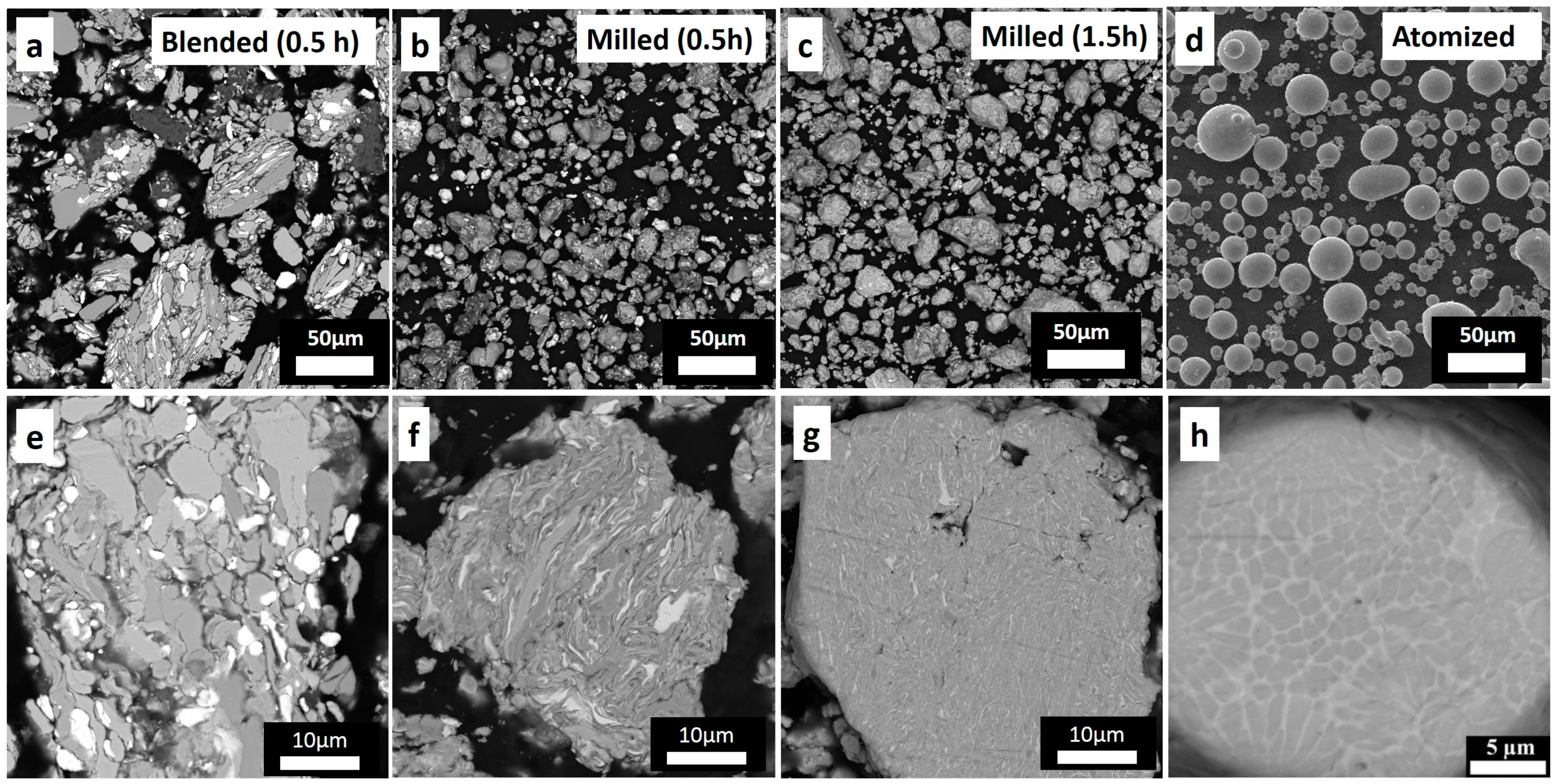
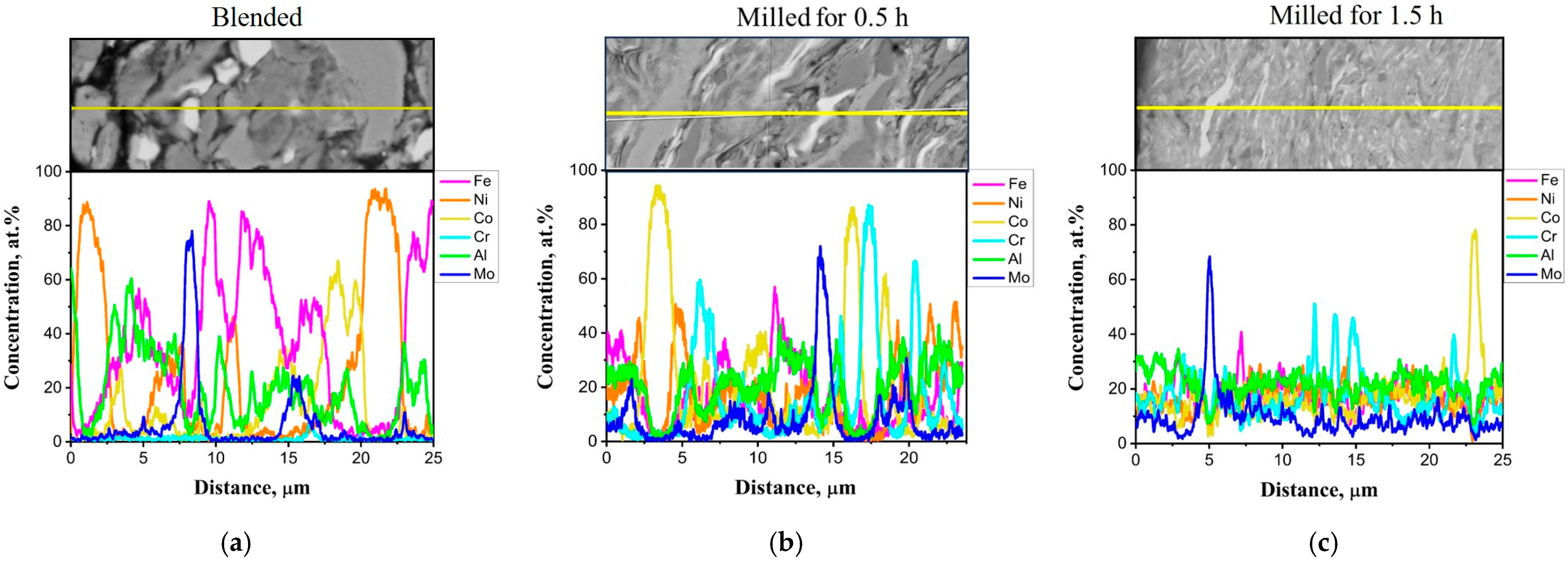
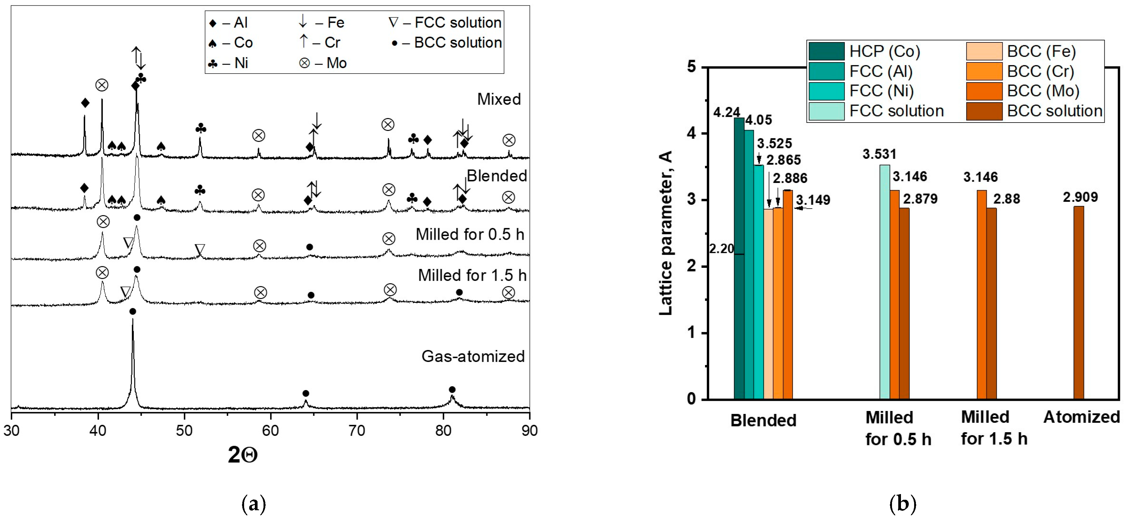
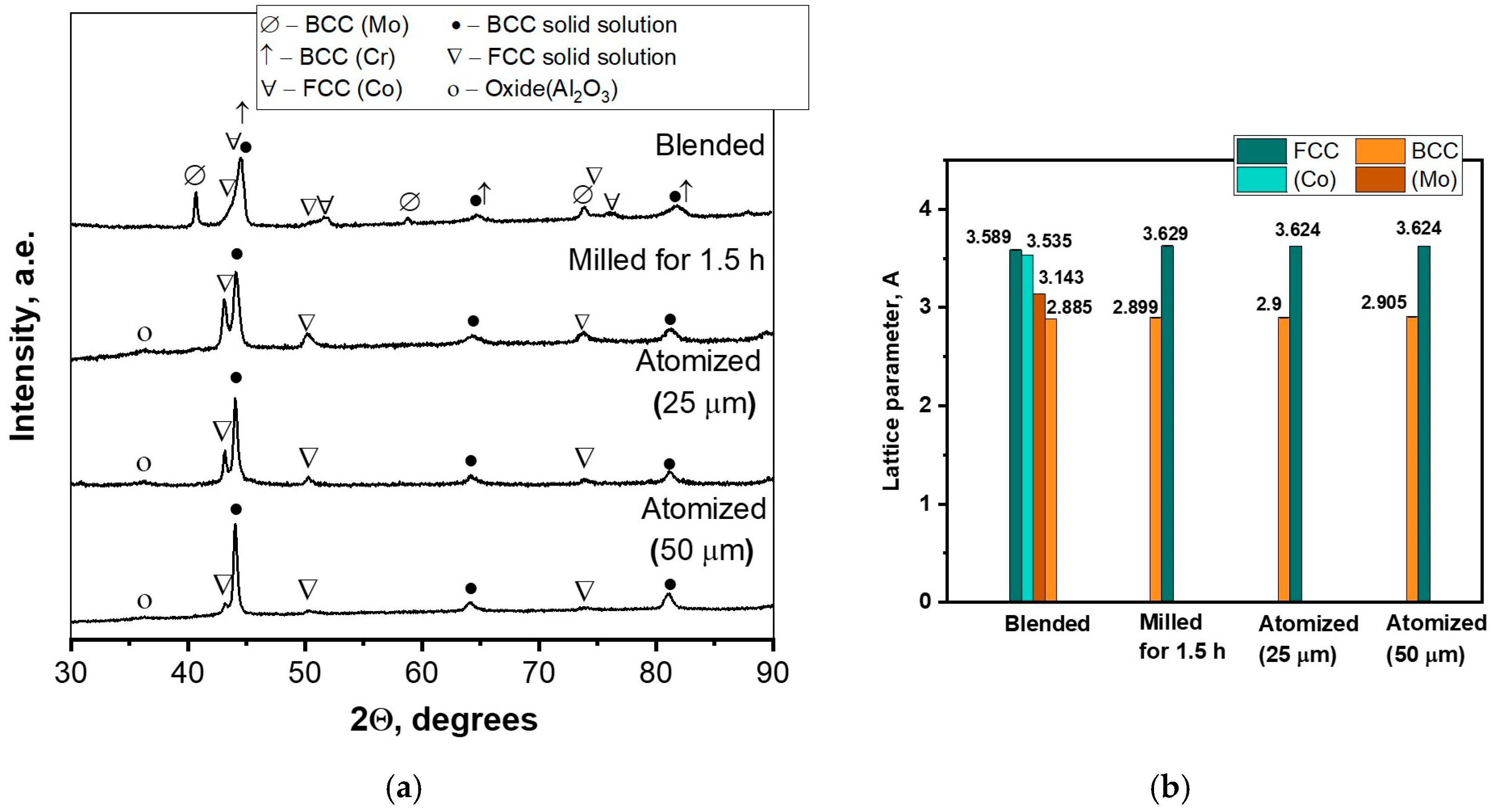
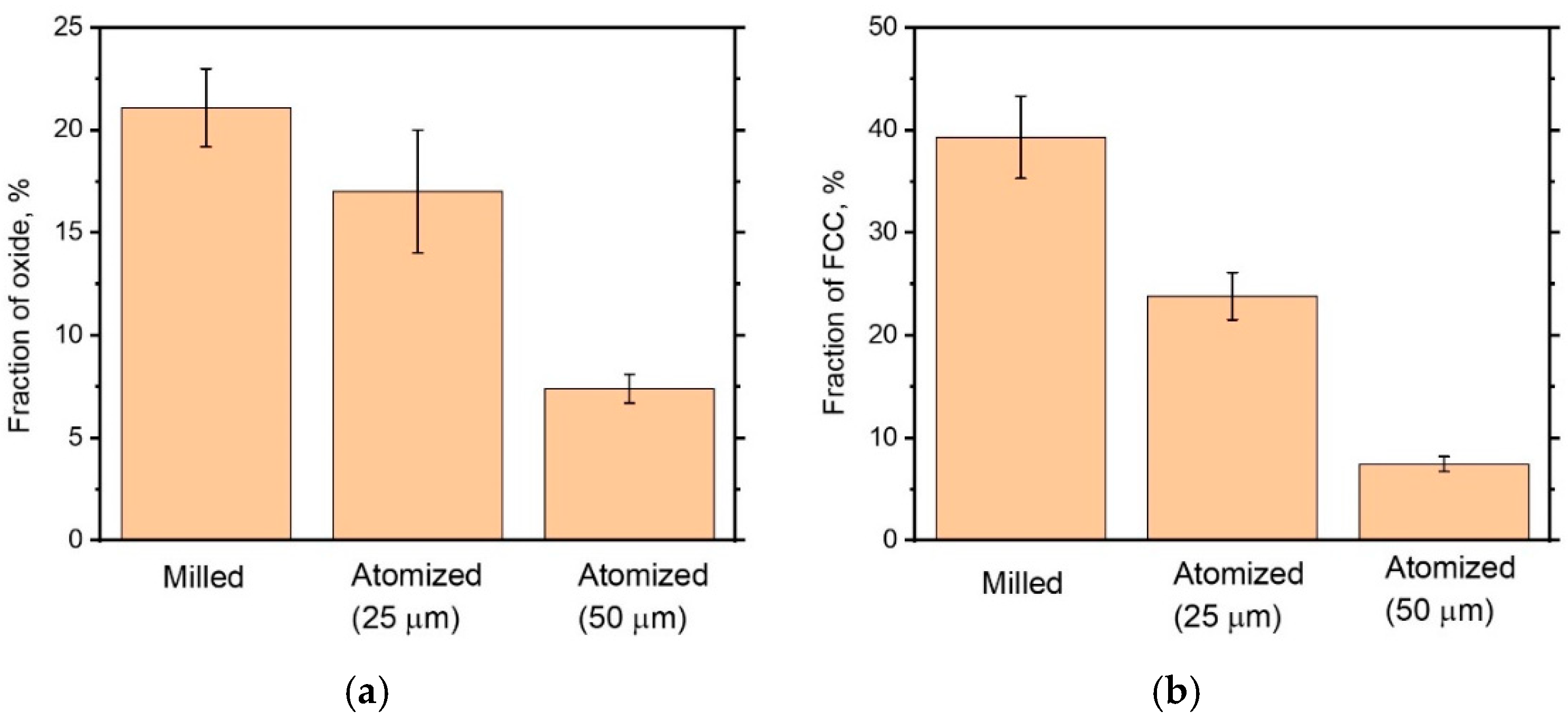
3.1. Powder Characterization

SEM images of the powders are shown in Figure 1. During the initial milling at lower energy (300 rpm), the metal particles flatten and agglomerate, forming big composite particles (Figure 1a,e). When the milling energy and time increase, the particles acquire a lamellar structure and shape close to equiaxed (Figure 1b,c,f,g). With an increase in milling time from 0.5 to 1.5 h, the particle size slightly increases from 10 to 20 μm due to agglomeration and cold welding.
The atomized powder consists of round particles with an average size of 25 µm (Figure 1d,h). The particles have a dendrite structure of partly ordered BCC/B2 supersaturated solid solution with Mo- and Cr-enriched segregation on the dendrites’ peripheries. [30,31].
The distribution of the elements in the powder depending on the milling parameter is shown in Figure 2. A longer milling time leads to thinner lamellas. The ability of the various metals to distribute within the particle volume in general depends on their yield strength, decreasing in the following sequence: Al; Ni; Fe; Co; Cr; Mo. After milling for 1.5 h, the particles become almost homogeneous; although the thin lamellar enriched with Mo, Co, and Cr still can be distinguished, their thickness, on average, does not exceed 0.5 µm.
The XRD patterns are shown in Figure 3a. After blending, the raw powder peaks moved slightly due to the formation of solid solutions. Milling led to a significant decrease in the intensity of the peaks and their widening due to solid solution formation and the accumulation of structural defects. During milling, the number of phases decreased from six to three: BCC (FeNiCoCrAl), BCC (Mo-based), and a trace of FCC solid solution (Figure 3b); the lattice parameters of the solid solutions determined by the peak’s gravity centers are presented in Figure 3b. An insignificant change in the lattice parameter of Mo indicates a slow process of dissolution. In contrast to the mechanically alloyed powder, the atomized powder reveals a one-phase structure—a BCC solid solution; however, as was found in [46], the BCC peaks have two sidebands denoting chemical liquation, which can also be observed in the microstructure (Figure 1h).
The powders produced via blending at 300 rpm, milling at 600 rpm for 1.5 h, and gas atomization were taken for subsequent coating deposition. To evaluate the influence of the granulometric composition on the coating structure, two batches of gas-atomized powders of different granulometric compositions were used. The first batch had a wide size distribution with an average particle size of 25 µm, and the second had a narrow size distribution from 45 µm to 63 µm with an average particle size of 50 µm. The chemical compositions obtained via EDS, phase compositions, and average particle size of the powders are presented in Table 3.

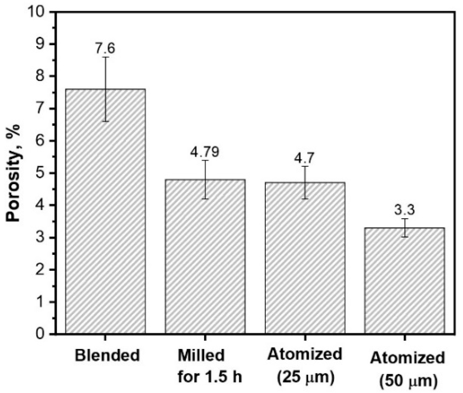
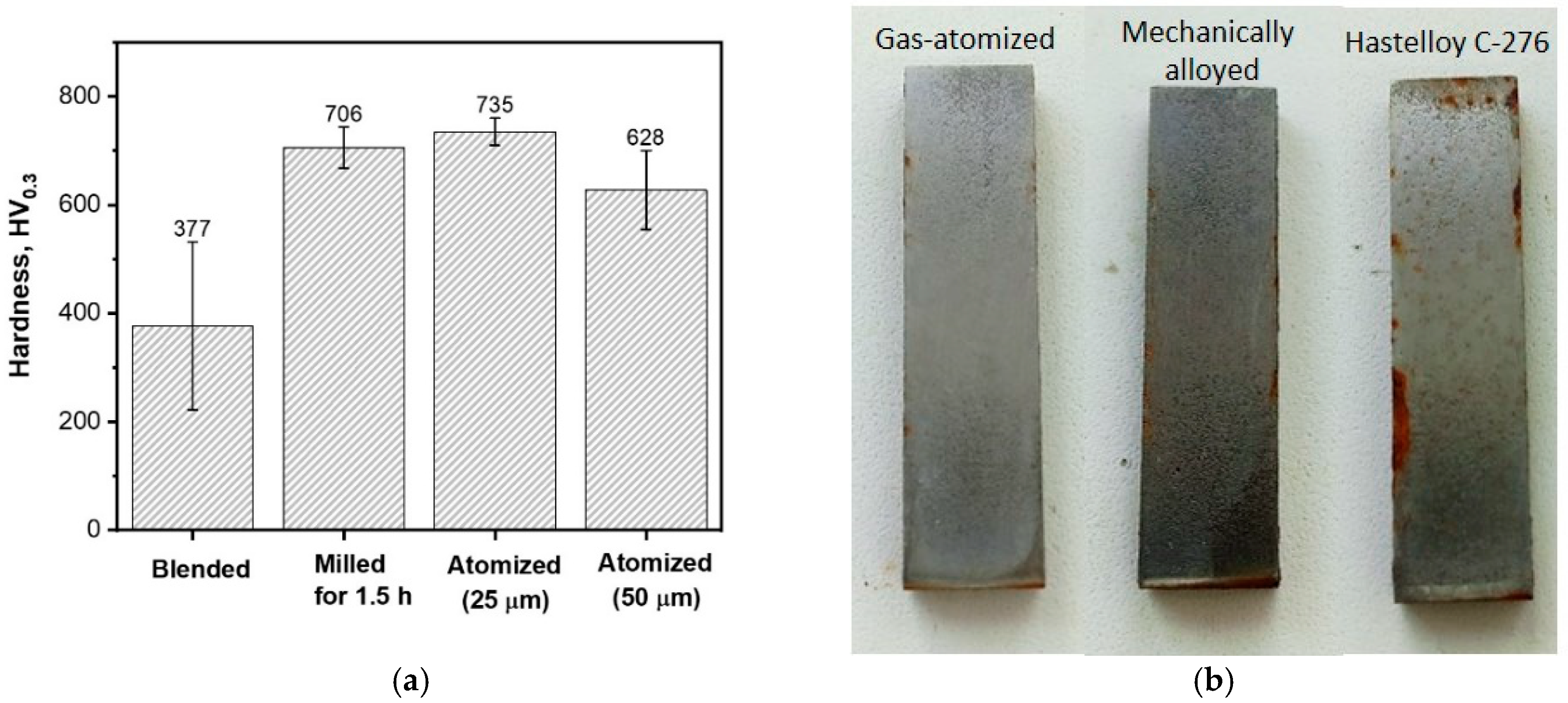
3.2. Coating Characterization

The microstructures of the deposited coatings are presented in Figure 4. The thickness of all coatings lies in the limits of 180–240 μm. All coatings have a layered structure; however, the coatings deposited from the gas-atomized powder contain non-melted and non-deformed particles of 20–40 µm, their amount is higher in the coatings deposited from 50 µm powder.
The microstructure of the coating deposited from the blended powder contains large undeformed non-melted particles and has high porosity, which makes its quality unsatisfactory. The porosities of the coatings produced from the milled and atomized powders with a particle size of 25 μm are equal within the error bar (Figure 5). The porosity of the coating produced via spraying the larger particles is lower.
As known [20], the spraying process and the quality of the coatings are affected by the technological properties of the feedstock powder. A spherical or nearly spherical shape and a narrow size distribution with an average size of about 40 μm are the most desirable. Therefore, we think that the main factor contributing to the high porosity of the coating deposited from the blended powder is the irregular shape, big size, and wide size distribution of the particles. This point of view is confirmed by the lowest porosity of the coating deposited from the gas-atomized powder with a narrow particle size distribution of 45–63 µm. On the other hand, as shown in Figure 1a,e and Figure 2a, the blended powder contains large particles of almost pure Cr, Co, and Mo. Since pure metals have a higher melting point than their solutions, they do not melt during spraying, and they retain their shape without filling the entire volume.
The element distributions in the coatings are presented in Figure 6. The coating produced from the blended powder is inhomogeneous; particles of Cr, Co, and Mo are clearly distinguished; and the high melting point and relatively large particle size prevent their homogenization during spraying. The chemical elements in the coating produced from the milled powder are almost uniformly distributed; only very thin layers enriched with Co, Cr, and Mo can still be observed. It can be assumed that during the spraying, along with heating caused by propane burning, the particles with a thin lamellar structure are additionally heated due to an exothermic reaction caused by the elements’ interaction. The total thermal energy is sufficient to homogenize the chemical composition.
The XRD patterns of the coatings are presented in Figure 7. The phase compositions of all coatings are different from those of the feedstock powders (Figure 3). In the coating deposited from the blended powder, FCC (Al) and HCP (Co) disappear, and instead of HCP (Co), peaks of FCC (Co) appear. The peaks belonging to FCC (Ni), BCC (Fe), and BCC (Cr) become lower and wider, overlapping with each other, which makes them undistinguished, and the peaks of BCC (Mo) are still clearly observed. Thus, comparing the EDS (Figure 6) and XRD (Figure 7) data, we can say that during the spraying, the components of the blended powder diffuse into each other; however, in general, they retain individual structures. Thermal energy was not enough to form a homogeneous structure. In contrast to what was discussed above, the XRD patterns of the coatings deposited from the milled and atomized powders have no peaks of the individual solid solutions; there are only two solid solutions (BCC and FCC) and a small amount of oxide (Al2O3 type). The phase compositions of the coatings deposited from the milled and the atomized powders are similar. Mo-based phase, which was observed in the milled powder (Figure 3), totally dissolves during the spraying.
Thus, blending involves the mixing and agglomeration of the powders without noticeable alloying. The particle size and shape mostly retain their qualities, leading to insufficient interactions under HVOF processing and an inhomogeneous coating microstructure. Therefore, for the considered HEA system, blending is not a recommended route for feedstock preparation for HVOF deposition.
The formation of FCC phase during FeNiCoCrMo0.5Al1.3 powder spraying was described earlier in [31] and has been explained by the destabilization of the BCC. It was found that during the spraying, Al interacts with oxygen, which leads to the formation of both oxide layers on the particles’ surface and Al-depleted areas underneath them, in which the BCC solid solution becomes unstable and an FCC structure forms. Therefore, the fraction of FCC depends on the oxidation extent and thus correlates with the oxide fraction (Figure 8). The powder with smaller particles demonstrates higher fractions of as oxide as well as FCC due to the higher specific surface (Figure 8).
The microhardness of the coatings is shown in Figure 9a. The microhardness of the coating deposited from the blended powder is the lowest with the largest deviation due to its inhomogeneous structure and high porosity. As can be seen in Figure 1a,e, the particles of the blended powder are large and consist of almost pure metals (Figure 2a and Figure 3). During the spraying, the components do not have enough time and sufficient energy to mix together and form a homogeneous structure. Therefore, the resulting coating (as seen in Figure 6 and Figure 7a) contains areas of different compositions showing different microhardness values. The coating deposited from the atomized powder with an average size of 25 μm has the highest microhardness, whereas the microhardness of the coatings deposited from the mechanically alloyed powder is slightly lower but coincides with the former within the error bar. The coating produced from the atomized powder with larger particles has a microhardness of about 100 HV lower, which can be explained by the lower structural defects and the lower oxide concentration (Figure 8a) compared with the coating deposited from the powder with a smaller particle size of 25 μm.
The corrosion resistance of the coatings produced from atomized powders and the mechanically alloyed powders of similar particle size was estimated via the salt fog chamber test for 672 h. For comparison, a coating produced from Hastelloy C-276 was subjected to the same procedure. The sample photographs after the test are presented in Figure 9b. The degree of corrosion damage for both coatings produced from FeNiCoCrMo0.5Al1.3 powders was determined to be 0%, and for Hastelloy C-276, it was 10%. Thus, the coatings deposited from both mechanically alloyed and gas-atomized powders demonstrate the same corrosion resistance superior to the reference coating.

4. Conclusions

In this work, high-entropy powders of FeNiCoCrMo0.5Al1.3 composition were prepared by the mechanical alloying of pure metal powders. Mechanical allowing was performed in a planetary mill utilizing different parameters: blending at 300 rpm for 0.5 h and milling at 600 rpm for 0.5, 1.0, and 1.5 h. The produced powders were used for coating deposition via HVOF spraying. The resulting coating’s structure, phase composition, and properties were compared with those produced via spraying of gas-atomized powder.
The blending of pure metal powders at 300 rpm for 0.5 h results in the mixing and agglomeration of the particles without noticeable alloying. The size and shape of the initial particles are mostly retained, which leads to insufficient interactions during HVOF processing. As a result, the microhardness of the coating deposited from the blended powder is the lowest with the largest deviation (377 ± 155 HV) due to its inhomogeneous structure and high porosity (about 8%). Thus, for the considered HEA system, blending is not a recommended route for feedstock preparation for HVOF deposition.
Milling at 600 rpm for 1.5 h allowed the production of mechanically alloyed particles with a homogeneous distribution of Fe, Ni, and Al and thin lamellas enriched with Co, Cr, and Mo within the particles. Only two BCC solutions (one of them Mo-based) were clearly distinguished by XRD.
The phase composition of the coating deposited from the mechanically alloyed (at 600 rpm) powder is the same as that of the coating deposited from the gas-atomized powder and consists of BCC, FCC solutions, and aluminum oxide. It is assumed that during the spraying, along with heating caused by propane burning, the particles with a thin lamellar structure are additionally heated due to an exothermic reaction caused by the elements’ interaction. The formation of FCC phase in the FeNiCoCrMo0.5Al1.3 composition during the powder spraying is explained by a destabilization of the BCC due to Al oxidation. The amounts of the FCC and oxide phases in the coatings correlate with each other and with the average particle size of the sprayed powder; the powders with a bigger average particle size have a lower concentration of oxides and FCC.
The structure, porosity, phase composition, microhardness, and corrosion resistance of the coatings produced from the mechanically alloyed powder and the gas-atomized powder of a similar particle size are similar. The coating has a porosity of 4.8 ± 0.6%, a microhardness of 706 ± 38 HV, and a corrosion resistance (visually estimated after salt fog chamber test at room temperature for 672 h) superior to that of Hastelloy C-276 coating.

Author Contributions

Conceptualization, T.L.; Methodology, T.L.; Investigation, A.S., S.S. and N.M.; Validation, A.S.; Data Curation, A.S.; Writing—Original Draft, A.S.; Writing—Review and Editing, T.L.; Supervision, O.T. All authors have read and agreed to the published version of the manuscript.

Funding

The research was partially funded by the Ministry of Science and Higher Education of the Russian Federation as part of the World-Class Research Center program: Advanced Digital Technologies (contract No. 075-15-2022-312 dated 20 April 2022).

Data Availability Statement

Data are contained within the article.

Conflicts of Interest

The authors declare no conflicts of interest.

References

  1. Cantor, B.; Chang, I.T.H.; Knight, P.; Vincent, A.J.B. Multicomponent Alloys. Mater. Sci. Eng. A 2004, 375–377, 213–218. [Google Scholar] [CrossRef]
  2. Yeh, J.W.; Chen, S.K.; Lin, S.J.; Gan, J.Y.; Chin, T.S.; Shun, T.T.; Tsau, C.H.; Chang, S.Y. Nanostructured High-Entropy Alloys with Multiple Principal Elements: Novel Alloy Design Concepts and Outcomes. Adv. Eng. Mater. 2004, 6, 299–303. [Google Scholar] [CrossRef]
  3. Miracle, D.B.; Senkov, O.N. A Critical Review of High Entropy Alloys and Related Concepts. Acta Mater. 2017, 122, 448–511. [Google Scholar] [CrossRef]
  4. Yang, X.; Zhang, Y. Prediction of High-Entropy Stabilized Solid-Solution in Multi-Component Alloys. Mater. Chem. Phys. 2012, 132, 233–238. [Google Scholar] [CrossRef]
  5. Sharma, P.; Dwivedi, V.K.; Dwivedi, S.P. Development of High Entropy Alloys: A Review. Mater. Today Proc. 2020, 43, 502–509. [Google Scholar] [CrossRef]
  6. Rogachev, A.S. Structure, Stability, and Properties of High-Entropy Alloys. Phys. Met. Metallogr. 2020, 121, 733–764. [Google Scholar] [CrossRef]
  7. Chen, Y.; Xie, B.; Liu, B.; Cao, Y.; Li, J.; Fang, Q.; Liaw, P.K. A Focused Review on Engineering Application of Multi-Principal Element Alloy. Front. Mater. 2022, 8, 816309. [Google Scholar] [CrossRef]
  8. Han, L.; Zhu, S.; Rao, Z.; Scheu, C.; Ponge, D.; Ludwig, A.; Zhang, H.; Gutfleisch, O.; Hahn, H.; Li, Z.; et al. Multifunctional high-entropy materials. Nat. Rev. Mater. 2024, 30, 1–20. [Google Scholar] [CrossRef]
  9. Wu, S.; Wang, G.; Wang, Q.; Jia, Y.; Yi, J.; Zhai, Q.; Liu, J.; Sun, B.; Chu, H.; Shen, J.; et al. Enhancement of strength-ductility trade-off in a high-entropy alloy through a heterogeneous structure. Acta Mater. 2019, 165, 444–458. [Google Scholar] [CrossRef]
  10. Gao, X.; Lu, Y.; Zhang, B.; Liang, N.; Wu, G.; Sha, G.; Liu, J.; Zhao, Y. Microstructural origins of high strength and high ductility in an AlCoCrFeNi2.1 eutectic high-entropy alloy. Acta Mater. 2017, 141, 59–66. [Google Scholar] [CrossRef]
  11. Wu, P.; Gan, K.; Yan, D.; Fu, Z.; Li, Z. A non-equiatomic FeNiCoCr high-entropy alloy with excellent anti-corrosion performance and strength-ductility synergy. Corros. Sci. 2021, 183, 109341. [Google Scholar] [CrossRef]
  12. Shi, Z.; Fang, Q.; Liaw, P.; Li, J. Corrosion-Resistant Biomedical High-Entropy Alloys: A Review. Adv. Eng. Mater. 2023, 25, 2300968. [Google Scholar] [CrossRef]
  13. Birbilis, N.; Choudhary, S.; Scully, J.R.; Taheri, M.L. A Perspective on Corrosion of Multi-Principal Element Alloys. Npj Mater. Degrad. 2021, 5, 2300968. [Google Scholar] [CrossRef]
  14. Lin, C.; Yao, Y. Corrosion-Resistant Coating Based on High-Entropy Alloys. Metals 2023, 13, 205. [Google Scholar] [CrossRef]
  15. Kong, D.; Guo, J.; Liu, R.; Zhang, X.; Song, Y.; Li, Z.; Guo, F.; Xing, X.; Xu, Y.; Wang, W. Effect of Remelting and Annealing on the Wear Resistance of AlCoCrFeNiTi0.5 High Entropy Alloys. Intermetallics 2019, 114, 106560. [Google Scholar] [CrossRef]
  16. Cui, Y.; Shen, J.; Manladan, S.M.; Geng, K.; Hu, S. Wear Resistance of FeCoCrNiMnAlx High-Entropy Alloy Coatings at High Temperature. Appl. Surf. Sci. 2020, 512, 145736. [Google Scholar] [CrossRef]
  17. Feng, C.; Wang, X.; Yang, L.; Guo, Y.; Wang, Y. High Hardness and Wear Resistance in AlCrFeNiV High-Entropy Alloy Induced by Dual-Phase Body-Centered Cubic Coupling Effects. Materials 2022, 15, 6896. [Google Scholar] [CrossRef]
  18. Lu, J.; Li, L.; Chen, Y.; Liu, X.; Zhao, X.; Guo, F.; Xiao, P. Y-Hf Co-Doped AlCoCrFeNi High-Entropy Alloy Coating with Superior Oxidation and Spallation Resistance at 1100 °C. Corros. Sci. 2021, 182, 109267. [Google Scholar] [CrossRef]
  19. Shajahan, S.; Kumar, A.; Chopkar, M.; Basu, A. Oxidation Study of CoCrCuFeNiSix High Entropy Alloys. Mater. Res. Express 2019, 7, 16532. [Google Scholar] [CrossRef]
  20. Meghwal, A.; Anupam, A.; Murty, B.S.; Berndt, C.C.; Kottada, R.S.; Ang, A.S.M. Thermal Spray High-Entropy Alloy Coatings: A Review. J. Therm. Spray Technol. 2020, 29, 857–893. [Google Scholar] [CrossRef]
  21. Tejero-Martin, D.; Rezvani Rad, M.; McDonald, A.; Hussain, T. Beyond Traditional Coatings: A Review on Thermal-Sprayed Functional and Smart Coatings. J. Therm. Spray Technol. 2019, 28, 598–644. [Google Scholar] [CrossRef]
  22. Fotovvati, B.; Namdari, N.; Dehghanghadikolaei, A. On Coating Techniques for Surface Protection: A Review. J. Manuf. Mater. Process. 2019, 3, 28. [Google Scholar] [CrossRef]
  23. Łatka, L.; Pawłowski, L.; Winnicki, M.; Sokołowski, P.; Małachowska, A.; Kozerski, S. Review of Functionally Graded Thermal Sprayed Coatings. Appl. Sci. 2020, 10, 5153. [Google Scholar] [CrossRef]
  24. Bhaskaran Nair, R.; Supekar, R.; Morteza Javid, S.; Wang, W.; Zou, Y.; McDonald, A.; Mostaghimi, J.; Stoyanov, P. High-Entropy Alloy Coatings Deposited by Thermal Spraying: A Review of Strengthening Mechanisms, Performance Assessments and Perspectives on Future Applications. Metals 2023, 13, 579. [Google Scholar] [CrossRef]
  25. Hsu, W.L.; Murakami, H.; Yeh, J.W.; Yeh, A.C.; Shimoda, K. On the Study of Thermal-Sprayed Ni0.2Co0.6Fe0.2CrSi0.2AlTi0.2 HEA Overlay Coating. Surf. Coat. Technol. 2017, 316, 71–74. [Google Scholar] [CrossRef]
  26. Li, T.; Liu, Y.; Liu, B.; Guo, W.; Xu, L. Microstructure and Wear Behavior of FeCoCrNiMo0.2 High Entropy Coatings Prepared by Air Plasma Spray and the High Velocity Oxy-Fuel Spray Processes. Coatings 2017, 7, 151. [Google Scholar]
  27. Rukhande, S.W.; Rathod, W.S.; Bhosale, D. High-Temperature Tribological Investigation of APS and HVOF Sprayed NiCrBSiFe Coatings on SS 316L. Tribol.-Mater. Surf. Interfaces 2022, 16, 98–109. [Google Scholar] [CrossRef]
  28. Rukhande, S.W.; Rathod, W.S. Tribological Behaviour of Plasma and HVOF-Sprayed NiCrSiBFe Coatings. Surf. Eng. 2020, 36, 745–755. [Google Scholar] [CrossRef]
  29. Löbel, M.; Lindner, T.; Lampke, T. High-Temperature Wear Behaviour of AlCoCrFeNiTi0.5 Coatings Produced by HVOF. Surf. Coat. Technol. 2020, 403, 126379. [Google Scholar] [CrossRef]
  30. Semikolenov, A.; Kuznetsov, P.; Bobkova, T.; Shalnova, S.; Klimova-Korsmik, O.; Klinkov, V.; Kobykhno, I.; Larionova, T.; Tolochko, O. Microstructure Evolution of FeNiCoCrAl1.3Mo0.5 High Entropy Alloy during Powder Preparation, Laser Powder Bed Fusion, and Microplasma Spraying. Materials 2021, 14, 7870. [Google Scholar] [CrossRef]
  31. Semikolenov, A.; Goshkoderya, M.; Uglunts, T.; Larionova, T.; Tolochko, O. Oxidation Behavior of FeNiCoCrMo0.5Al1.3 High-Entropy Alloy Powder. Materials 2024, 17, 531. [Google Scholar] [CrossRef] [PubMed]
  32. Chen, L.; Bobzin, K.; Zhou, Z.; Zhao, L.; Öte, M.; Königstein, T.; Tan, Z.; He, D. Wear Behavior of HVOF-Sprayed Al0.6TiCrFeCoNi High Entropy Alloy Coatings at Different Temperatures. Surf. Coat. Technol. 2019, 358, 215–222. [Google Scholar] [CrossRef]
  33. Huang, P.K.; Yeh, J.W.; Shun, T.T.; Chen, S.K. Multi-Principal-Element Alloys with Improved Oxidation and Wear Resistance for Thermal Spray Coating. Adv. Eng. Mater. 2004, 6, 74–78. [Google Scholar] [CrossRef]
  34. Wang, L.M.; Chen, C.C.; Yeh, J.W.; Ke, S.T. The Microstructure and Strengthening Mechanism of Thermal Spray Coating NixCo0.6Fe0.2CrySi ZAlTi0.2 High-Entropy Alloys. Mater. Chem. Phys. 2011, 126, 880–885. [Google Scholar] [CrossRef]
  35. Hsu, W.L.; Yang, Y.C.; Chen, C.Y.; Yeh, J.W. Thermal Sprayed High-Entropy NiCo0.6Fe0.2Cr1.5SiAlTi0.2 Coating with Improved Mechanical Properties and Oxidation Resistance. Intermetallics 2017, 89, 105–110. [Google Scholar] [CrossRef]
  36. Srivastava, M.; Jadhav, M.S.; Chethan; Chakradhar, R.P.S.; Singh, S. Investigation of HVOF Sprayed Novel Al1.4Co2.1Cr0.7Ni2.45Si0.2Ti0.14 HEA Coating as Bond Coat Material in TBC System. J. Alloys Compd. 2022, 924, 166388. [Google Scholar] [CrossRef]
  37. Srivastava, M.; Jadhav, M.; Chethan; Chakradhar, R.P.S.; Muniprakash, M.; Singh, S. Synthesis and Properties of High Velocity Oxy-Fuel Sprayed FeCoCrNi2Al High Entropy Alloy Coating. Surf. Coat. Technol. 2019, 378, 124950. [Google Scholar] [CrossRef]
  38. Yin, S.; Li, W.; Song, B.; Yan, X.; Kuang, M.; Xu, Y.; Wen, K.; Lupoi, R. Deposition of FeCoNiCrMn High Entropy Alloy (HEA) Coating via Cold Spraying. J. Mater. Sci. Technol. 2019, 35, 1003–1007. [Google Scholar] [CrossRef]
  39. Patel, P.; Nair, R.B.; Supekar, R.; McDonald, A.; Chromik, R.R.; Moreau, C.; Stoyanov, P. Enhanced Wear Resistance of AlCoCrFeMo High Entropy Coatings (HECs) through Various Thermal Spray Techniques. Surf. Coat. Technol. 2024, 477, 130311. [Google Scholar] [CrossRef]
  40. Addepalli, S.N.; Joladarashi, S.; Ramesh, M.R. Elevated Temperature Tribological Performance of Non-Equiatomic CoCrNiTiWx High Entropy Alloy Coatings Developed by Mechanical Alloying and High-Velocity Oxy-Fuel Spray. Surf. Coat. Technol. 2024, 476, 130267. [Google Scholar] [CrossRef]
  41. Löbel, M.; Lindner, T.; Kohrt, C.; Lampke, T. Processing of AlCoCrFeNiTi High Entropy Alloy by Atmospheric Plasma Spraying. Proc. IOP Conf. Ser. Mater. Sci. Eng. Inst. Phys. Publ. 2017, 181, 012015. [Google Scholar] [CrossRef]
  42. Cheng, K.C.; Chen, J.H.; Stadler, S.; Chen, S.H. Properties of Atomized AlCoCrFeNi High-Entropy Alloy Powders and Their Phase-Adjustable Coatings Prepared via Plasma Spray Process. Appl. Surf. Sci. 2019, 478, 478–486. [Google Scholar] [CrossRef]
  43. Vaidya, M.; Muralikrishna, G.M.; Murty, B.S. High-Entropy Alloys by Mechanical Alloying: A Review. J. Mater. Res. 2019, 34, 664–686. [Google Scholar] [CrossRef]
  44. Torralba, J.M.; Alvaredo, P.; García-Junceda, A. High-entropy alloys fabricated via powder metallurgy. A critical review. Powder Metall. 2019, 62, 84–114. [Google Scholar] [CrossRef]
  45. GOST 9.308-85; Unified System of Corrosion and Ageing Protection. Metal and Non-Metal Inorganic Coatings. Methods for Accelerated Corrosion Tests. USSR State Committee for Standards: Moscow, Russia, 1985.
  46. Larionova, T.; Semikolenov, A.; Kuznetsov, P.; Shalnova, S.; Tolochko, O. Phase Transformation and Strengthening of the Gas-Atomized FeCoCrNiMo0.5Al1.3 Eutectic High-Entropy Alloy Powder during Annealing. Heliyon 2024, 10, 8. [Google Scholar] [CrossRef]
Figure 1. SEM images of the powder particles: (a,e)—blended, (b,f)—milled for 0.5 h, (c,g)—milled for 1.5 h, and (d,h)—gas-atomized.
Jmmp 08 00280 g001
Figure 2. EDS line scan element distribution in dependence on the milling parameter: (a) blended at 300 rpm for 0.5 h; (b) milled at 600 rpm for 0.5 h; (c) milled at 600 rpm for 1.5 h.
Jmmp 08 00280 g002
Figure 3. X-ray diffraction patterns of the powders (a) and the lattice parameters of the phases (b).
Jmmp 08 00280 g003
Figure 4. Optical microscopy images of the coatings deposited from: blended powder (a), milled powder (b), gas-atomized powder with a size of 50 µm (c), and gas-atomized powder with a size of 25 µm (d).
Jmmp 08 00280 g004
Figure 5. Porosity of the coatings produced from the different powders.
Jmmp 08 00280 g005
Figure 6. Element mapping data of the coating deposited from the powder prepared via different methods.
Jmmp 08 00280 g006
Figure 7. X-ray diffraction patterns of the coatings (a) and the lattice parameters of the phases (b).
Jmmp 08 00280 g007
Figure 8. Fraction of oxide (a) and FCC (b) in the coatings deposited from milled and gas-atomized powders.
Jmmp 08 00280 g008
Figure 9. Microhardness of the coatings (a) and the coatings surface after salt fog chamber test for 672 h (b).
Jmmp 08 00280 g009
Table 1. Literature data on HEA feedstock powders produced by different methods and coatings deposited from them.
Chemical CompositionPowder Preparation ProcedureCoating Deposition MethodAverage Particle Size (µm)Feedstock Powder Phase Composition Coating Phase CompositionCoating MicrohardnessReferences
AlCoCrFeNiTiMixing of pure metal powders and pre-alloyed FeCr13APS41.3BCC1
FCC(Ni)
HCP(Ti)
Oxide
BCC1
FCC(Ni)
HCP(Ti)
Oxide
354 HV0.1[41]
AlSiTiCrFeCoNiMo0.5Milling of the pre-alloyed ingotAPS-BCC
FCC1
FCC2
BCC
Oxide
524 HV[33]
Ni0.2Co0.6Fe0.2CrSi0.2AlTi0.2Milling of the pre-alloyed ingotAPS44BCC
Cr3Si
minor FCC
BCC
Cr3Si
Oxide
429 HV5[35]
Al1.4Co2.1Cr0.7Ni2.45Si0.2Ti0.2Milling of the mechanically alloyed at 300 rpm for 5 h and then compacted bulkHVOF15–20FCC
BCC
FCC
BCC
Oxide
814 HV0.1[36]
FeCoCrNi2AlMilling of the mechanically alloyed at 300 rpm for 2 h and then compacted bulkHVOF15FCC
BCC
FCC
BCC
Oxide
600 HV[37]
AlCoCrFeNiTi0.5Gas atomizationHVOF26.5BCCBCC
Oxide
610 HV0.1[29]
FeCoCrNiMo0.2Gas atomizationHVOF15–45FCCFCC
Oxides
356 HV0.2[26]
AlCoCrFeNiTiGas atomizationAPS42.9BCC1
BCC2
BCC1
BCC2
Oxide
599HV0.1[42]
Al1.3FeCoCrNiMo0.5Gas atomizationAPS25BCCFCC
BCC
Oxide
650 HV0.05[30]
Al1.3FeCoCrNiMo0.5Gas atomizationHVOF25BCCFCC
BCC
Oxide
750 HV0.05[31]
AlCoCrFeMon/aHVOF27BCC1(AlCoCrFe) BCC2(CrMo)BCC1
BCC2
Oxides
702 HV0.3[39]
CoCrNiTiWBall milling at 200 rpm for 10 hHVOF22.7–
27.6
BCC1
BCC2
BCC1
BCC2
Oxides
863–1025 HV0.3[40]
AlCoCrFeNiTiHigh-energy ball milling at 400–700 rpm for 14 hAPS-BCC1
FCC(Ni)
HCP(Ti)
BCC1
BCC2
FCC
Oxide
476 HV0.1[29]
Table 2. HVOF spraying parameters.
Oxygen Flow Rate, L/minPropane Flow Rate,
L/min
Spray Distance,
mm
Powder Feed Rate,
rpm
Number of CyclesTorch Velocity, m/min
250601505.265
Table 3. Characteristics of the powder used for deposition.
Preparation MethodChemical Composition, Mass.%Average Particles Size,
μm
Phase Composition
NiCrMoFeCoAlSi
Blending
(at 300 rpm)
18.916.716.218.118.911.1-45BCC (Mo); BCC (Fe); BCC (Cr); FCC (Ni); FCC (Al); HCP (Co)
Milling
(at 600 rpm)
18.916.716.218.119.011.1-20BCC; BCC (Mo)
Gas atomization
(0–63 μm)
19.016.416.518.018.911.10.125BCC
Gas atomization
(45–63 μm)
19.016.416.717.918.911.10.150
Casting
(nominal alloy’s composition)
19.016.516.717.918.811.10.1-B2; σ
Disclaimer/Publisher’s Note: The statements, opinions and data contained in all publications are solely those of the individual author(s) and contributor(s) and not of MDPI and/or the editor(s). MDPI and/or the editor(s) disclaim responsibility for any injury to people or property resulting from any ideas, methods, instructions or products referred to in the content.

