Article

Enriching Laser Powder Bed Fusion Part Data Using Category Theory

by
Yuchu Qin
1,
Shubhavardhan Ramadurga Narasimharaju
2,
Qunfen Qi
3,*,
Shan Lou
1,
Wenhan Zeng
1,
Paul J. Scott
1 and
Xiangqian Jiang
1
1
EPSRC Future Advanced Metrology Hub, University of Huddersfield, Huddersfield HD1 3DH, UK
2
Additive Manufacturing Advancing South East Project, South East Technological University, Waterford X91 K0EK, Ireland
3
School of Electrical, Electronic and Mechanical Engineering, University of Bristol, Bristol BS8 1QU, UK
*
Author to whom correspondence should be addressed.
J. Manuf. Mater. Process. 2024, 8(4), 130; https://doi.org/10.3390/jmmp8040130
Submission received: 28 May 2024 / Revised: 18 June 2024 / Accepted: 21 June 2024 / Published: 24 June 2024

Abstract

:
Laser powder bed fusion (LPBF) is a promising metal additive manufacturing technology for producing functional components. However, there are still a lot of obstacles to overcome before this technology is considered mature and trustworthy for wider industrial applications. One of the biggest obstacles is the difficulty in ensuring the repeatability of process and the reproducibility of products. To tackle this challenge, a prerequisite is to represent and communicate the data from the part realisation process in an unambiguous and rigorous manner. In this paper, a semantically enriched LPBF part data model is developed using a category theory-based modelling approach. Firstly, a set of objects and morphisms are created to construct categories for design, process planning, part build, post-processing, and qualification. Twenty functors are then established to communicate these categories. Finally, an application of the developed model is illustrated via the realisation of an LPBF truncheon.

1. Introduction

Laser powder bed fusion (LPBF), sometimes referred to as selective laser melting or direct metal laser melting, is an additive manufacturing (AM) technique that builds nearly net-shaped components by selectively melting and fusing metallic powders together with a high power density laser beam [1,2]. This technique provides the ability to achieve complicated geometries at no additional expense and a high degree of design freedom. There are common advantages of AM techniques over traditional manufacturing technologies. More significantly, high strength, stiffness, and nearly full density metallic components may be fabricated thanks to the LPBF technique [3]. As a result, LPBF has been regarded as one of the most promising metal AM techniques for making functioning parts in the industry [4].
Despite the fact that the LPBF process has shown attractive advantages and great potential, there are still a lot of obstacles to overcome before this technology is considered mature and trustworthy for wider industrial applications [5]. One of the biggest obstacles is the difficulty in ensuring the repeatability of the process and the reproducibility of products [6]. To tackle this challenge, a prerequisite is to represent and communicate the data from the part realisation process in an unambiguous and rigorous manner, since this is of importance for identifying the complex relationships among material properties, design specifications, process variables, post-processes, and product quality [7,8,9,10,11].
For the representation and communication of LPBF part data, a straightforward way is to use some standardised data formats, such as the standard tessellation language (STL) format, 3D (three-dimensional) manufacturing file (3MF) format, additive manufacturing file (AMF) format, Wavefront object (OBJ) format, and standard for the exchange of product model data format. This way is simple and effective, but the standardised data formats mostly focus on the representation of geometric data and do not support the representation of many other types of part data. In addition, the part data encoded by them lacks explicit semantics and contexts to be exchanged across part realisation-related applications [10].
In the literature, there are various approaches for representing non-geometric data in the AM part realisation process, which could be applied to the LPBF process. Specifically, Kumar and Dutta [12] presented a non-manifold boundary representation-based method to model the geometry, topology, and materials of heterogeneous objects; Kou and Tan [13] presented a new data structure of a heterogeneous feature tree to meet the demand of modelling the material distributions of a heterogeneous object; Kou et al. [14] proposed a method that uses non-manifold heterogeneous cells to represent the heterogeneous objects with intricate geometry and complex material distributions; Ingole et al. [15] developed a coding system to express the geometry and process information of AM parts; Ko et al. [16] presented a finite state automata-based method to model AM design information to enable customised AM; Lu et al. [17] designed an integrated data schema for AM processes; Prater [18] developed an AM database to organise and store the data from design, post-processing, and mechanical testing; Feng et al. [19] constructed an activity model to structurally describe the process-related data in LPBF; Wang et al. [20] established a Bayesian networks-based knowledge management model to support design for AM; Bonnard et al. [21] constructed a hierarchical object-oriented model for the AM of digital thread; Liu et al. [22] presented a digital twin-enabled platform for collaboratively managing metal AM data. These approaches can work well for their specific purposes, but the issue of representation of AM part data semantics has not been addressed in them.
To make AM part data semantics explicit, context-aware, and shareable among part realisation-related applications, a popular approach is to use ontologies. It is commonly known that ontology, an explicit and formalised specification of a shared conceptualisation model, can facilitate the reuse of domain knowledge, structure domain terminologies, and describe data semantics explicitly [23]. Despite having its origins in the Semantic Web, ontology has found widespread use in numerous other domains. In the field of AM, Liu and Rosen [24] presented an ontology-based knowledge representation and reuse method for AM process design; Witherell et al. [25] built several ontology-based metamodels for reusing AM process models; Roh et al. [26] constructed several ontology-based laser and heat metamodels for metal AM; Lu et al. [27] proposed an ontology-based digital solution for integrated and collaborative AM; Dinar and Rosen [28] constructed a general ontology for AM design; Hagedorn et al. [29] developed an ontology-based approach for creative design in AM; Liang [30] established an ontology-based knowledge framework for AM process design; Kim et al. [31] constructed an AM design ontology to facilitate analysis of manufacturability; Sanfilippo et al. [32] built an ontology-based model for AM; Ali et al. [33] constructed an ontology that represents product life cycle knowledge in AM; Xiong et al. [34] developed an ontology-based process design platform for wire arc AM; Ko et al. [35] studied construction of rules for AM design based on ontology and machine learning; Chen et al. [36] constructed an ontology-based Bayesian network model to represent the causal links between AM design and process parameters, as well as structure and mechanical properties; Roh et al. [37] established an ontology-based process map capturing all data in a metal AM process chain; Mayerhofer et al. [38] developed an ontology that represent the information regarding the capabilities of AM processes, materials, and machines; Li et al. [39] developed an ontology for knowledge representation in LPBF process planning; Roh et al. [40] created network-based ontologies that capture the relationship between process variables and sensor data in real-time, as well as the relationship between as-built component characteristics and related physical phenomena; Hasan et al. [41] established an ontological framework for process defects knowledge modelling in LPBF; Park et al. [42] presented an ontology-based framework to facilitate collaborative knowledge management in the identification of data analytics opportunities in AM; Wang et al. [43] built an ontology-supported embedding learning system for defect diagnosis in AM; Wang et al. [44] developed an ontology for eco-design in AM that incorporates informative sustainability analysis. It is clear that ontologies not only support the representation of AM part data themselves, but, most importantly, have the capability to represent AM part data semantics explicitly and to facilitate their reuse. However, using ontologies may probably not be a satisfactory approach for AM part data representation as a whole, since the expressive capability of an ontology is limited by its decidability and additional mappings are needed to implement the communications between different ontologies.
Category theory (CT) is an abstract mathematical theory which was invented by Eilenberg and MacLane [45] in the 1940s. It can be used as a rigorous, flexible, and coherent modelling language across the sciences [46]. A CT-based modelling approach not only has the capability to describe the semantics explicitly, but also provides a natural mechanism for reasoning on a category and a direct solution for mappings between different categories [47]. Because of these characteristics, this approach has been widely used in engineering. Spivak and Kent [48] presented a categorical framework for knowledge representation in complex mechanical systems; Baez and Fong [49] developed a categorical framework for modelling passive linear networks in electrical and mechanical systems; Brown et al. [50] explored categorical data integration for computational science; Baez and Master [51] studied the use of a categorical structure to model and analyse complex systems; Bakirtzis et al. [52] presented a category-theoretic framework to make various composition types explicit in cyber–physical system modelling and analysis; Aguinaldo et al. [53] developed a category theoretic framework for robotic interoperability through the use of goal-oriented programming.
In this paper, a CT-based modelling approach is introduced to develop a semantically enriched LPBF part data model. The remainder of the paper is organised as follows. A brief introduction of some prerequisites related to categorical modelling is provided in Section 2. Section 3 explains the details of the presented LPBF part data enrichment model. An implementation and an illustration of the application of the model are documented in Section 4. Section 5 ends the paper with a conclusion.

2. CT-Based Modelling

A category C consists of a collection of objects C O and a collection of morphisms C M that satisfy the following conditions:
  • For each morphism M in C M , there are two objects O 1 and O 2 in C O that are, respectively, called the domain and codomain of the morphism. The morphism is denoted as M : O 1 O 2 . The domain and codomain of the morphism are, respectively, denoted as d o m ( M ) = O 1 and c o d ( M ) = O 2 ;
  • For any three objects O 1 , O 2 , and O 3 in C O and any two morphisms M 1 and M 2 in C M , if M 1 : O 1 O 2 and M 2 : O 2 O 3 , then there is a morphism M 2 M 1 : O 1 O 3 called the composition of M 1 and M 2 ;
  • For each object O in C O , there is an identity morphism I O : O O that satisfies M 1 I O = M 1 and I O M 2 = M 2 for any two morphisms M 1 and M 2 in C M satisfying d o m ( M 1 ) = O and c o d ( M 2 ) = O .
In CT-based modelling, reasoning on a category can be performed via a set of inherent morphism structures, which mainly include the following [47]:
  • Triangle structure: If there are two morphisms M 1 : O 1 O 2 and M 2 : O 2 O 3 among three objects O 1 , O 2 , and O 3 in a category C , then a new morphism M 3 : O 1 O 3 can be generated in C (see Figure 1a);
  • Rectangle structure: If there are four morphisms M 1 : O 1 O 2 , M 2 : O 1 O 3 , M 3 : O 2 O 4 , and M 4 : O 3 O 4 among four objects O 1 , O 2 , O 3 , and O 4 in a category C , then a new morphism M 5 : O 1 O 4 can be generated in C (see Figure 1b);
  • Product structure: If there are four morphisms M 1 : O 1 O 2 , M 2 : O 1 O 3 , M 3 : O 4 O 2 , and M 4 : O 4 O 3 among four objects O 1 , O 2 , O 3 , and O 4 in a category C , then a new morphism M 5 : O 4 O 1 can be generated in C (see Figure 1c);
  • Coproduct structure: If there are four morphisms M 1 : O 2 O 1 , M 2 : O 3 O 1 , M 3 : O 2 O 4 , and M 4 : O 3 O 4 among four objects O 1 , O 2 , O 3 , and O 4 in a category C , then a new morphism M 5 : O 1 O 4 can be generated in C (see Figure 1d);
  • Pullback structure: If there are six morphisms M 1 : O 1 O 2 , M 2 : O 3 O 1 , M 3 : O 4 O 2 , M 4 : O 3 O 4 , M 5 : O 5 O 1 , and M 6 : O 5 O 4 among five objects O 1 , O 2 , O 3 , O 4 , and O 5 in a category C , then a new morphism M 7 : O 5 O 3 can be generated in C (see Figure 1e);
  • Pushout structure: If there are six morphisms M 1 : O 2 O 1 , M 2 : O 1 O 3 , M 3 : O 2 O 4 , M 4 : O 4 O 3 , M 5 : O 1 O 5 , and M 6 : O 4 O 5 among five objects O 1 , O 2 , O 3 , O 4 , and O 5 in a category C , then a new morphism M 7 : O 3 O 5 can be generated in C (see Figure 1f).
CT provides a direct solution for mappings between categories. This solution is to use functors. A functor F is a mapping from a category C 1 to a category C 2 , denoted as F : C 1 C 2 , which associates each object O in C 1 to an object F ( O ) in C 2 and associates each morphism M : O 1 O 2 in C 1 to a morphism F ( M ) : F ( O 1 ) F ( O 2 ) in C 2 , such that identity morphisms and composition of morphisms are preserved.
In CT-based modelling, the instances of objects are called elements [47]. Given a collection of elements C E , a collection of objects C O , a collection of morphisms C M , a collection of categories C C , a collection of functors C F , and an interpretation I = ( D , I ) for ( C E , C O , C M , C C , C F ) , such that D is the object domain and I is an interpretation function, the semantics of all constructors can be defined based on direct model-theoretic semantics, which are listed as follows:
  • Element: e I D ;
  • Object: O I D ;
  • Morphism: M I D × D ;
  • Category: C I D ( D × D ) ;
  • Functor: ( F : C 1 C 2 ) I O I D C 1 . [ ( F ( O ) ) I D C 2 ] ( M : O 1 O 2 ) I D C 1 × D C 1 . [ ( F ( M ) : F ( O 1 ) F ( O 2 ) ) I D C 2 × D C 2 ] O , M 1 , M 2 C 1 . [ F ( I O ) = I F ( O ) F ( M 1 M 2 ) = F ( M 1 ) F ( M 2 ) ] ;
  • Triangle structure: ( O 1 I , O 2 I ) M 1 I ( O 2 I , O 3 I ) M 2 I ( O 1 I , O 3 I ) M 3 I ;
  • Rectangle structure: ( O 1 I , O 2 I ) M 1 I ( O 1 I , O 3 I ) M 2 I ( O 2 I , O 4 I ) M 3 I ( O 3 I , O 4 I ) M 4 I ( O 1 I , O 4 I ) M 5 I ;
  • Product structure: ( O 1 I , O 2 I ) M 1 I ( O 1 I , O 3 I ) M 2 I O 4 , M 3 , M 4 . [ ( O 4 I , O 2 I ) M 3 I ( O 4 I , O 3 I ) M 4 I ] ! M 5 . [ ( O 4 I , O 1 I ) M 5 I M 1 M 5 = M 3 M 2 M 5 = M 4 ] ;
  • Coproduct structure: ( O 2 I , O 1 I ) M 1 I ( O 3 I , O 1 I ) M 2 I O 4 , M 3 , M 4 . [ ( O 2 I , O 4 I ) M 3 I ( O 3 I , O 4 I ) M 4 I ] ! M 5 . [ ( O 1 I , O 4 I ) M 5 I M 5 M 1 = M 3 M 5 M 2 = M 4 ] ;
  • Pullback structure: ( O 1 I , O 2 I ) M 1 I ( O 3 I , O 1 I ) M 2 I ( O 4 I , O 2 I ) M 3 I ( O 3 I , O 4 I ) M 4 I M 1 M 2 = M 3 M 4 M 1 M 5 = M 3 M 6 ! M 7 . [ ( O 5 I , O 3 I ) M 7 I M 2 M 7 = M 5 M 4 M 7 = M 6 ] ;
  • Pushout structure: ( O 2 I , O 1 I ) M 1 I ( O 1 I , O 3 I ) M 2 I ( O 2 I , O 4 I ) M 3 I ( O 4 I , O 3 I ) M 4 I M 2 M 1 = M 4 M 3 M 5 M 1 = M 6 M 3 ! M 7 . [ ( O 3 I , O 5 I ) M 7 I M 7 M 2 = M 5 M 7 M 4 = M 6 ] .

3. Semantically Enriched Model

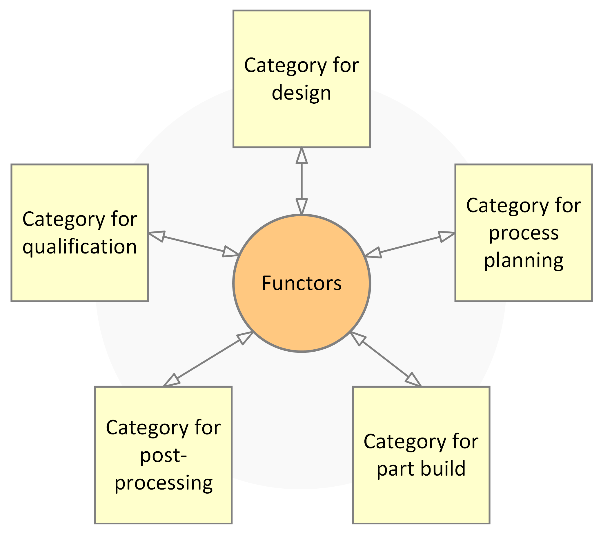
The LPBF part realisation process generally consists of five stages, which are design, process planning, part build, post-processing, and qualification. LPBF part data include all relevant data captured, used, and generated in these stages. In this section, a semantically enriched model of LPBF part data is presented using a CT-based modelling approach. The overall structure of the presented model is shown in Figure 2. The model consists of five categories constructed to represent the data in the five stages and twenty functors among these categories constructed to exchange the data among the five stages. In the following subsections, the details of each category will be explained.

3.1. Category for Design

The design of LPBF is a stage of designing an LPBF product, where the product’s functional performance as well as other important life cycle factors like cost, dependability, and manufacturing feasibility are optimised [54]. There are two tasks in this stage:
  • Conceptual design: The definition of an LPBF product’s form and function is done in this initial task of the LPBF part realisation process. It describes the suggested LPBF product in concept sketches and entails the design of processes, strategies, interactions, and experiences [55];
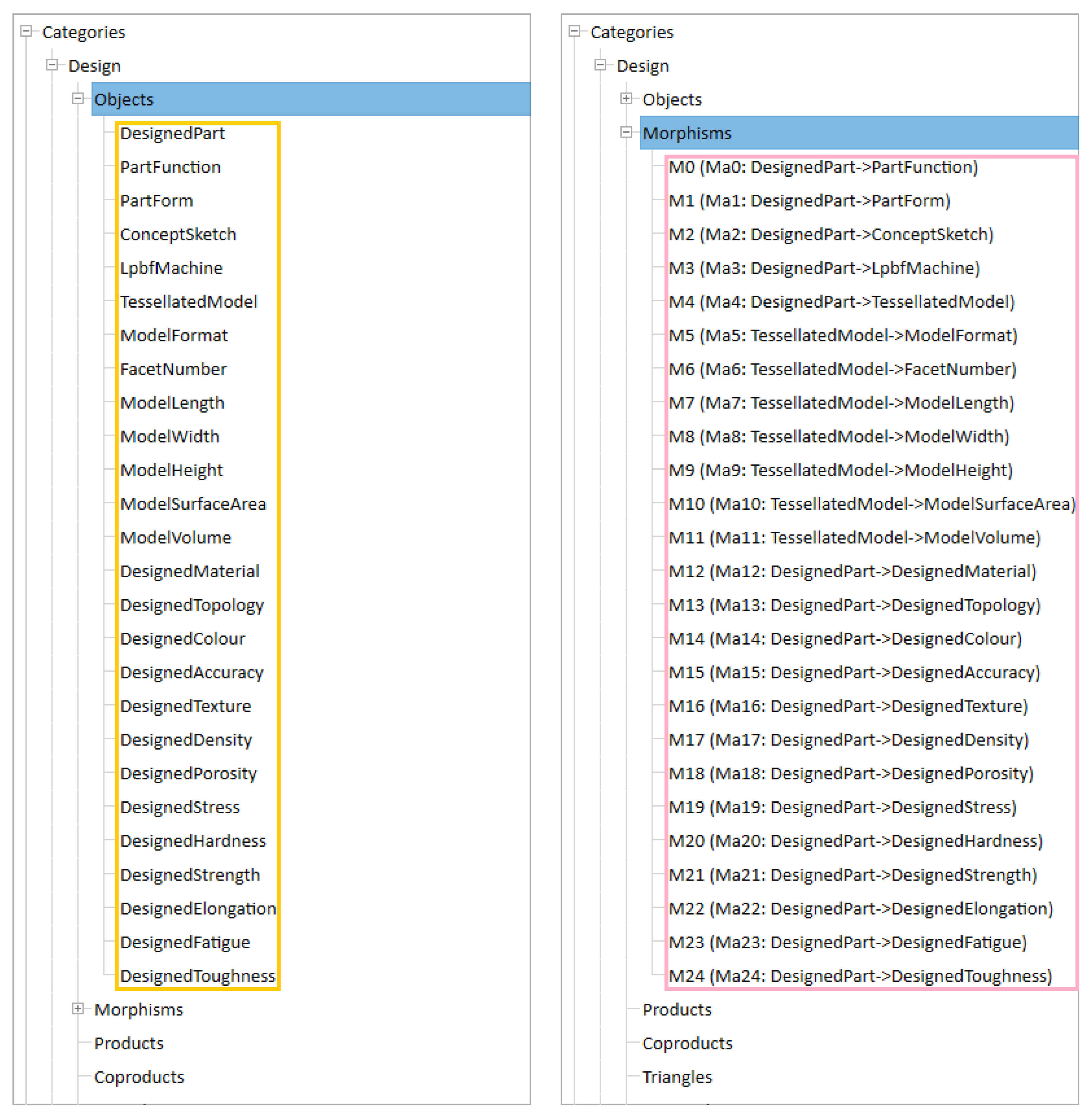
  • Detailed design: This task involves creating plans, specifications, estimates, and refining the design. Choosing an LPBF machine to manufacture a product and designing its geometry and parameters are typically included in detailed design. Reverse engineering or computer-aided design (CAD) modelling are two methods for designing geometry. Based on the conceptual design results, CAD modelling is carried out in a CAD system, producing a tessellated 3D model of the product. Reverse engineering generates a tessellated 3D model of a component from its two-dimensional image or physical model. A tessellated 3D model is encoded in a specific format, such as the STL format, 3MF format, AMF format, and OBJ format. The basic geometric information of a tessellated 3D model include number of facets, length, width, height, surface area, and volume. The specifications to be designed could include material, topology, colour, accuracy, surface texture, density, porosity, residual stress, hardness, strength, elongation, fatigue, and toughness [56].
Based on the description above, a category for design named Design was constructed. This category consists of twenty-six objects and twenty-five morphisms. The details are shown in Figure 3.

3.2. Category for Process Planning

Process planning is a step when machining procedures and associated parameters are decided upon in order to transform a workpiece from an engineering drawing to its final form in traditional subtractive manufacturing. A tessellated 3D model and the LPBF process, respectively, take the place of the engineering design and machining operations in LPBF. Process planning’s goal is still the same: identifying specific LPBF process variables that will allow for precise and effective part manufacturing. The four subsequent tasks that make up process planning for LPBF are part orientation [57], support generation [58], 3D model slicing [59], and path planning [59,60], as follows:
  • Part orientation seeks to ascertain an appropriate build orientation based on the LPBF part’s tessellated 3D model and particular manufacturing constraints. The build orientation of an LPBF part is represented by two angles in the majority of the LPBF process planning tools currently in use: α and β . This ensures that, after rotating the tessellated 3D model around the X and Y axes by α and β , respectively, the build orientation lines up along the Z axis (the XOY plane is parallel to the build platform). The tessellated 3D model is the result of the design stage. The production requirements are specified based on several characteristics influenced by build orientation, which generally comprise hardness, strength, elongation, residual stress, fatigue, part accuracy, surface texture, support structure, build time, build cost, post-processing time, and post-processing cost [57];
  • Support generation focuses on generating the minimum amount of support structure required for building the part on the basis of its tessellated 3D model in the determined build orientation. In LPBF, a support structure can be used to balance a building component to prevent shift or collapse, sustain the overhanging areas to prevent deformation or collapse, or lessen part distortion brought on by temperature gradients. Three importance indicators for describing support structure are geometry, shape, volume, and supported region area. The geometry is usually encoded in the same format as the tessellated 3D model. The shapes of support structures that are applicable for the LPBF process mainly include lattice shape, cellular shape, unit cell shape, tree shape, pin shape, Y shape, and IY shape [58]. The volume of the support structure can be calculated from its geometry. The area of supported region can be obtained from an analysis of the overhanging facets of the tessellated 3D model;
  • 3D model slicing entails slicing a tessellated 3D model with the created support structure in the build orientation to ascertain the thickness of individual layers and the geometry of the contour to be gathered. A slice is each individual layer [59]. Typically, a proprietary file format, such as the stereo lithography contour format, the common layer interface format, or the Hewlett-Packard graphics language format [10], is used to encode the slice data, which consists of the layer thickness and contour geometry;
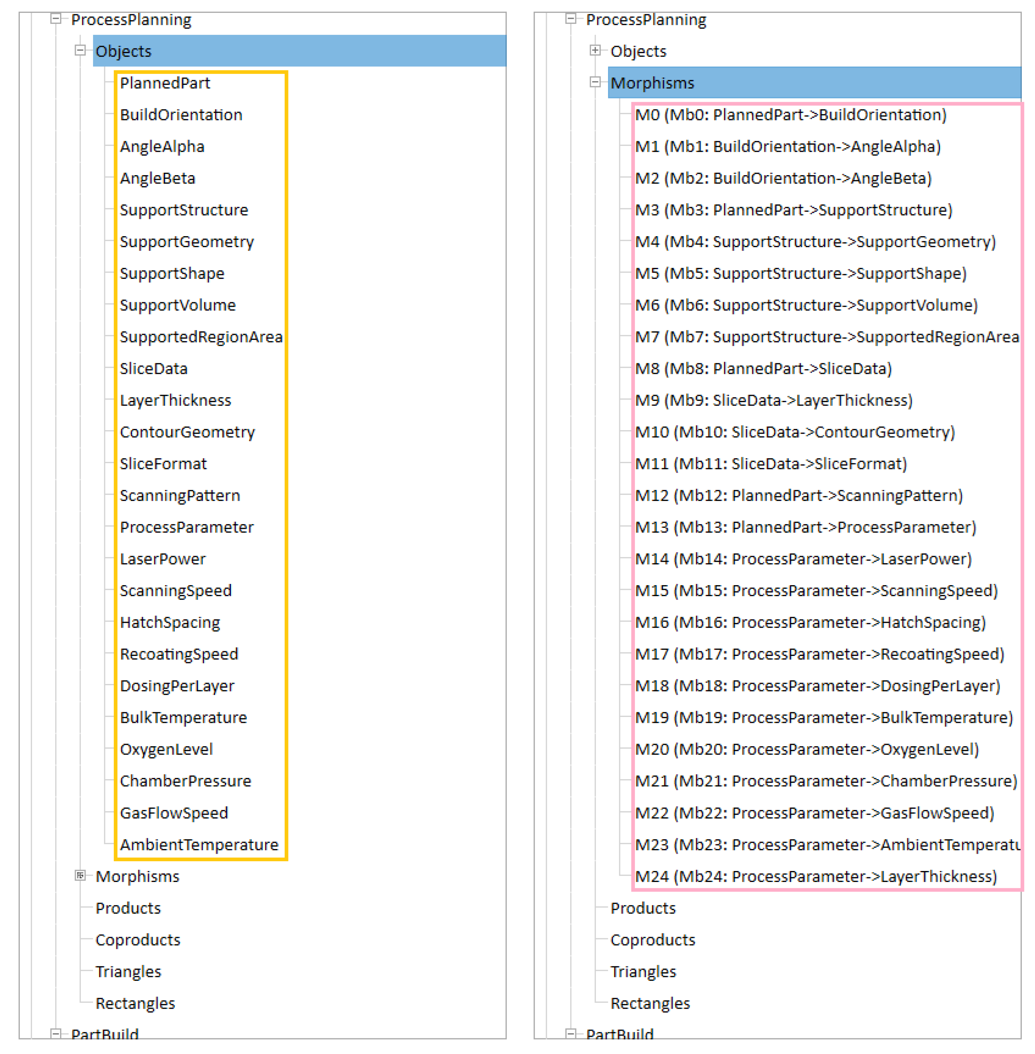
  • Path planning focuses on planning the laser scanning path and process parameters to fabricate each layer from the identified slices. An important step in path planning is to select a proper scanning pattern. In general, alternative patterns mainly include tge raster pattern, zigzag pattern, grid pattern, spiral pattern, contour pattern and hybrid pattern [59,60]. Another important step is to specify a group of optimal process parameters. According to the study of Liu et al. [22], controllable process parameters mainly include laser power, scanning speed, hatch spacing, recoating speed, dosing per layer, bulk temperature, oxygen level, chamber pressure, gas flow speed, and ambient temperature.
Based on the description above, a category for process planning named ProcessPlanning was constructed. This category consists of twenty-five objects and twenty-five morphisms. The details are shown in Figure 4.

3.3. Category for Part Build

The process of creating an LPBF part utilising a particular LPBF machine is known as LPBF part build. There are three steps in this stage: setup, build, and teardown. The tessellated 3D model, specifications, and process variables defined in the design and process planning stages are imported into the employed LPBF machine and transformed into information that can be interpreted by the machine during the setup step. After that, the machine is set up and the material is ready. The machine begins building the part after all the necessary preparations are finished. Typically, the build step is connected to the process signature monitoring. The as-built component is taken out of the machine and cleanup is done during the teardown phase.
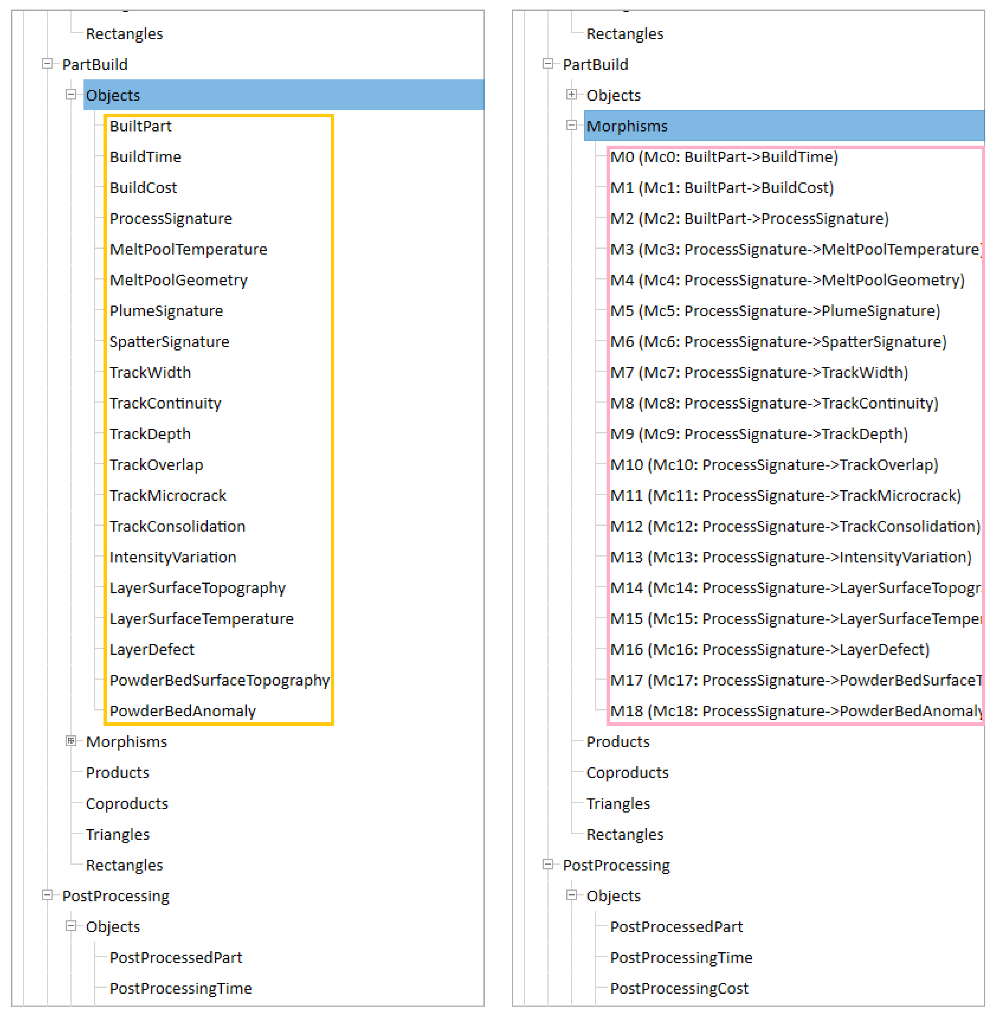
In the stage of part build for LPBF, two important data items are build time and build cost. Further, the data that have an important influence on the quality of the final product include a series of process signatures. According to the study of Liu et al. [22], these process signatures can be classified into melt pool signatures, by-product signatures, single track signatures, single layer signatures, and powder bed signatures. The melt pool signatures include melt pool temperature and melt pool geometry. The by-product signatures contain plume signature and spatter signature. The single track signatures include track width, track continuity, track depth, track overlap, track microcrack, and track consolidation. The single layer signatures contain intensity variation, layer surface topography, layer surface temperature, and layer defect. The powder bed signatures include powder bed surface topography and powder bed anomaly. Based on the description above, a category for part build named PartBuild was constructed. This category consists of twenty objects and nineteen morphisms. The details are shown in Figure 5.

3.4. Category for Post-Processing

In most cases, post-processing is required for an LPBF part in order to meet design requirements. Support removal and property, accuracy, surface, and appearance improvements are examples of post-processing for LPBF [7]. Enhancing LPBF parts’ mechanical and physical qualities using heat treatment techniques like hot isostatic pressing, annealing, and quenching is beneficial. It is typically done to release any residual stresses prior to removing the support structure. Certain tools or instruments, such as a bandsaw and a wire-electrical discharge machining instrument, can be used to remove the support structure. A part made using the LPBF method often has less geometric accuracy than one made using traditional machining techniques, and dimensional variability is also frequently encountered. Drilling, sharp edge contour machining, and adaptive raster milling are typically needed to increase accuracy and decrease variability. Surface improvement is typically required in LPBF post-processing since the staircase effect and the usage of a support structure can both lead to poor surface quality. The common techniques for this enhancement are painting, hardening, and shot peening. The purpose of appearance improvement is to enhance the built part’s attractiveness. Common methods for enhancing appearance include painting, priming, and polishing.
In the stage of post-processing for LPBF, two important data items are post-processing time and post-processing cost. The data items related to property enhancement include treatment method, sequence, atmosphere, heating rate, final temperature, holding time, cooling rate, and cooling medium [22]. The data items related to support removal contain removal method, machining type, water type, wire diameter, and fixture setup. The data items related to accuracy improvement include machining method and machining plan. The data items related to surface improvement contain finishing method and finishing plan [9]. The data items related to appearance improvement include process method and process plan.
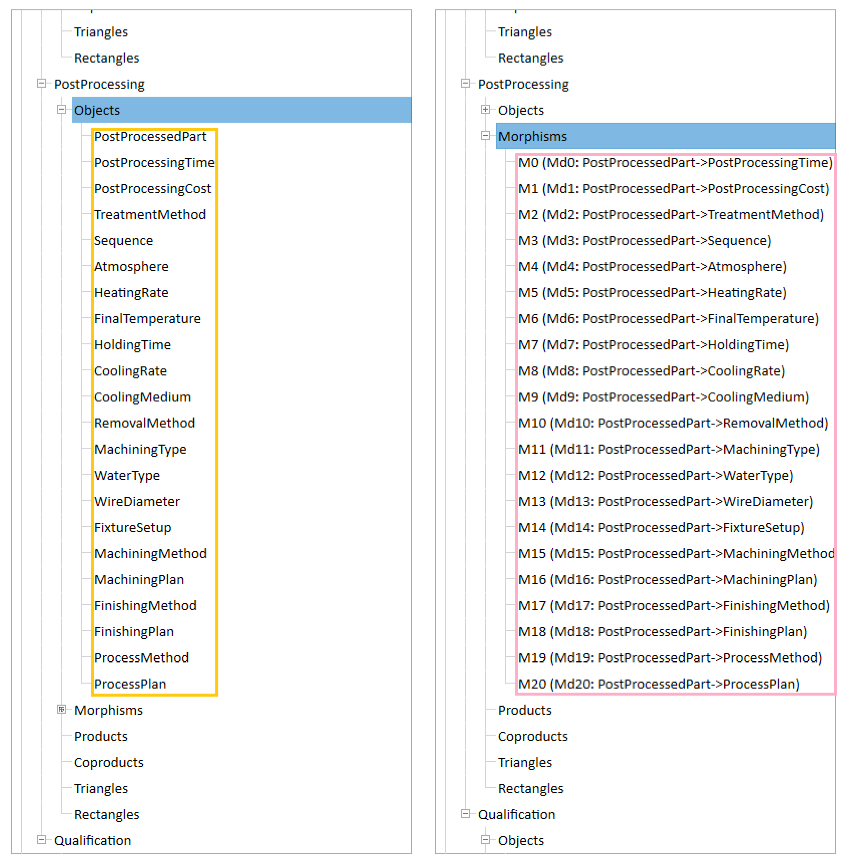
Based on the description above, a category for post-processing named PostProcessing was constructed. This category consists of twenty-two objects and twenty-one morphisms. The details are shown in Figure 6.

3.5. Category for Qualification

The final step in LPBF part realisation process is qualification. To find out if the requirements created during the design stage have been met, this step measures the post-processed component’s accuracy, surface texture, defects, and properties. Coordinate-measuring machine, 3D optical scanner, and industrial computed tomography scanner are common measurement and inspection tools for part accuracy. Areal topography and profile topography measurements are the two basic components of surface texture inspection. A contact stylus is often used for profile topography assessment. A wider range of technologies and instruments are available for measuring areal topography, such as confocal microscopy, conoscopic holography, atomic force microscopy, focus variation microscopy, coherence scanning interferometry, and the elastomeric sensor [61]. Non-destructive evaluation methods include stereomicroscope, thermography, acoustic emission, remote visual, and ultrasonic inspections, which are commonly used for defect inspection. Part density, part porosity, residual stress, hardness, strength, elongation, fatigue, and toughness are the primary properties of an LPBF part. Both ISO/ASTM 52904 (2019) [62] and ISO/ASTM 52927 (2024) [63] contain documentation of the testing procedures for part characteristics.
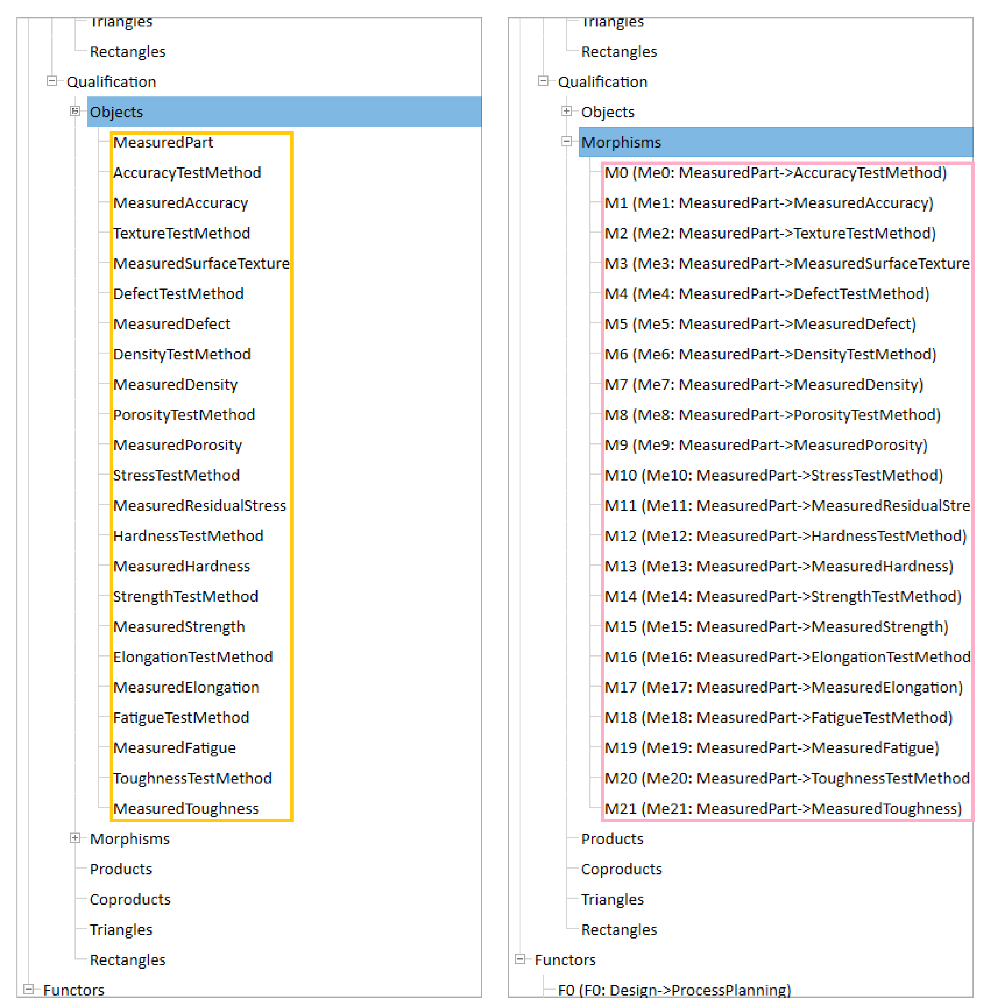
In the stage of qualification for LPBF, the important data items include accuracy test method, measured accuracy, texture test method, measured surface texture, defect test method, measured defect, density test method, measured density, porosity test method, measured porosity, stress test method, measured residual stress, hardness test method, measured hardness, strength test method, measured strength, elongation test method, measured elongation, fatigue test method, measured fatigue, toughness test method, and measured toughness [9,22].
Based on the description above, a category for qualification named Qualification was constructed. This category consists of twenty-three objects and twenty-two morphisms. The details are shown in Figure 7.

4. Implementation and Illustration

In this section, a prototype implementation of the constructed semantically enriched model of LPBF part data is first reported. Then, a case study is presented to illustrate the application of the developed model.

4.1. Implementation

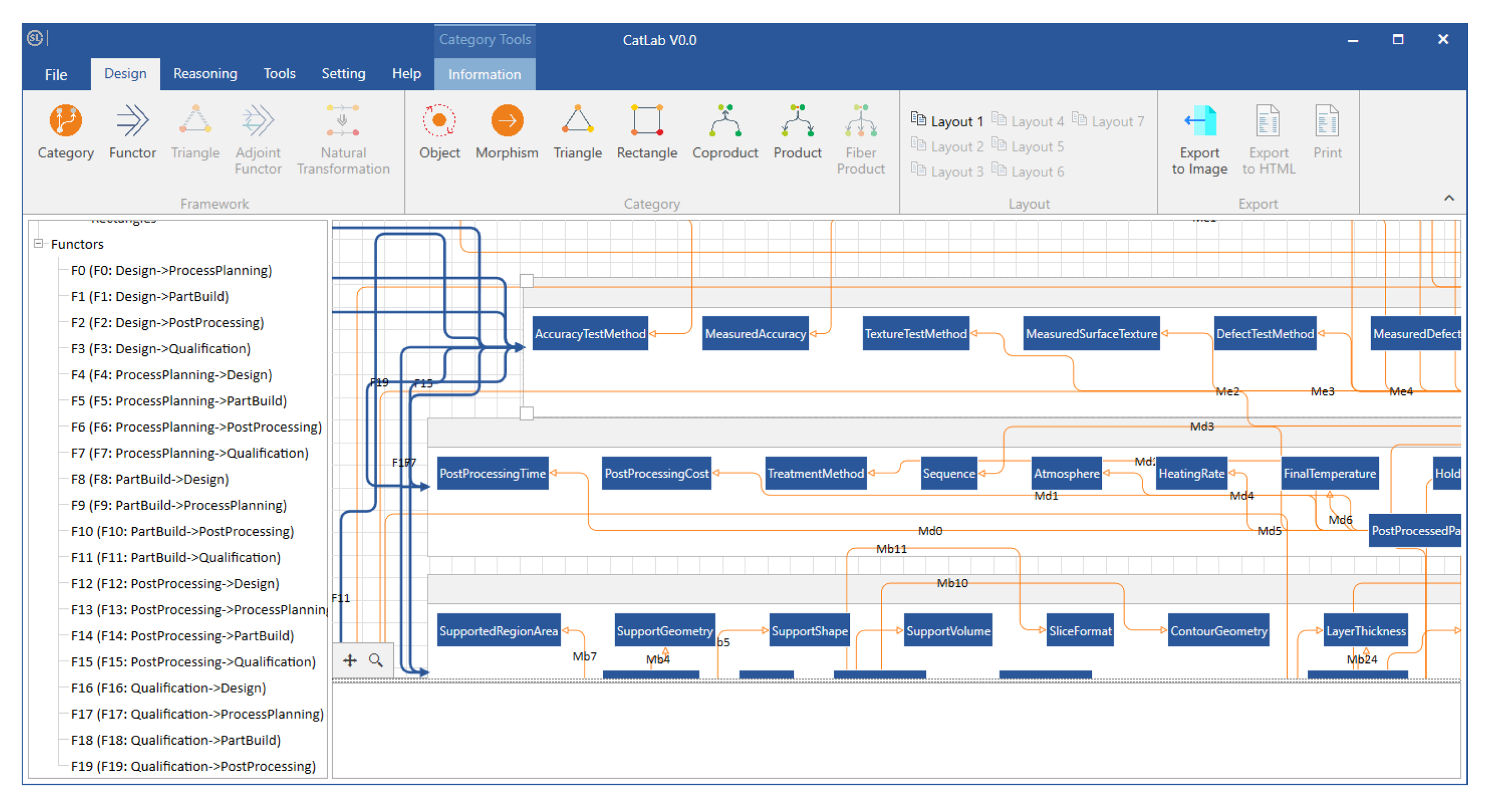
The semantically enriched model of LPBF part data was developed using CatLab, a CT-based modelling software tool that is currently under development by the authors’ research group. A partial visual representation of the developed model is shown in Figure 8.

4.2. Illustration

A representation of the data of a truncheon built by LPBF [64] is presented to illustrate the application of the developed model. Based on the five stages of the LPBF part realisation process, the process of this representation can be divided into five steps.
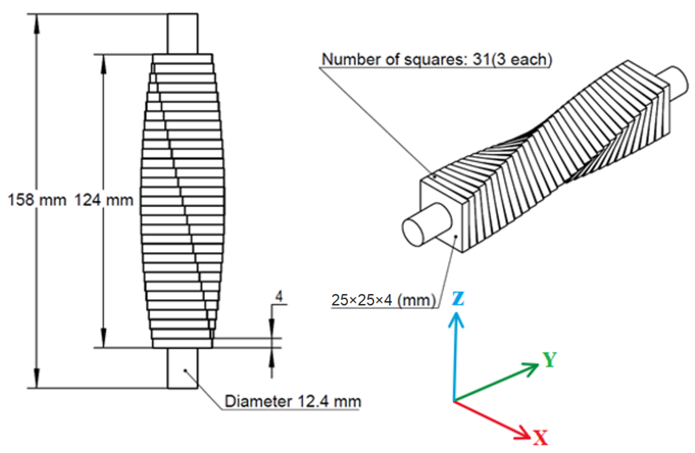
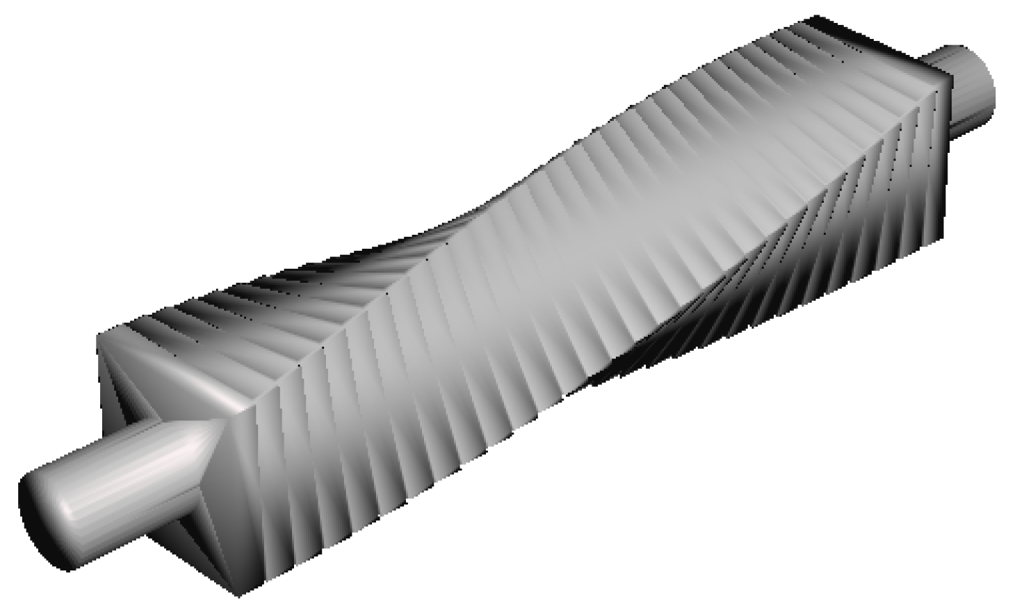
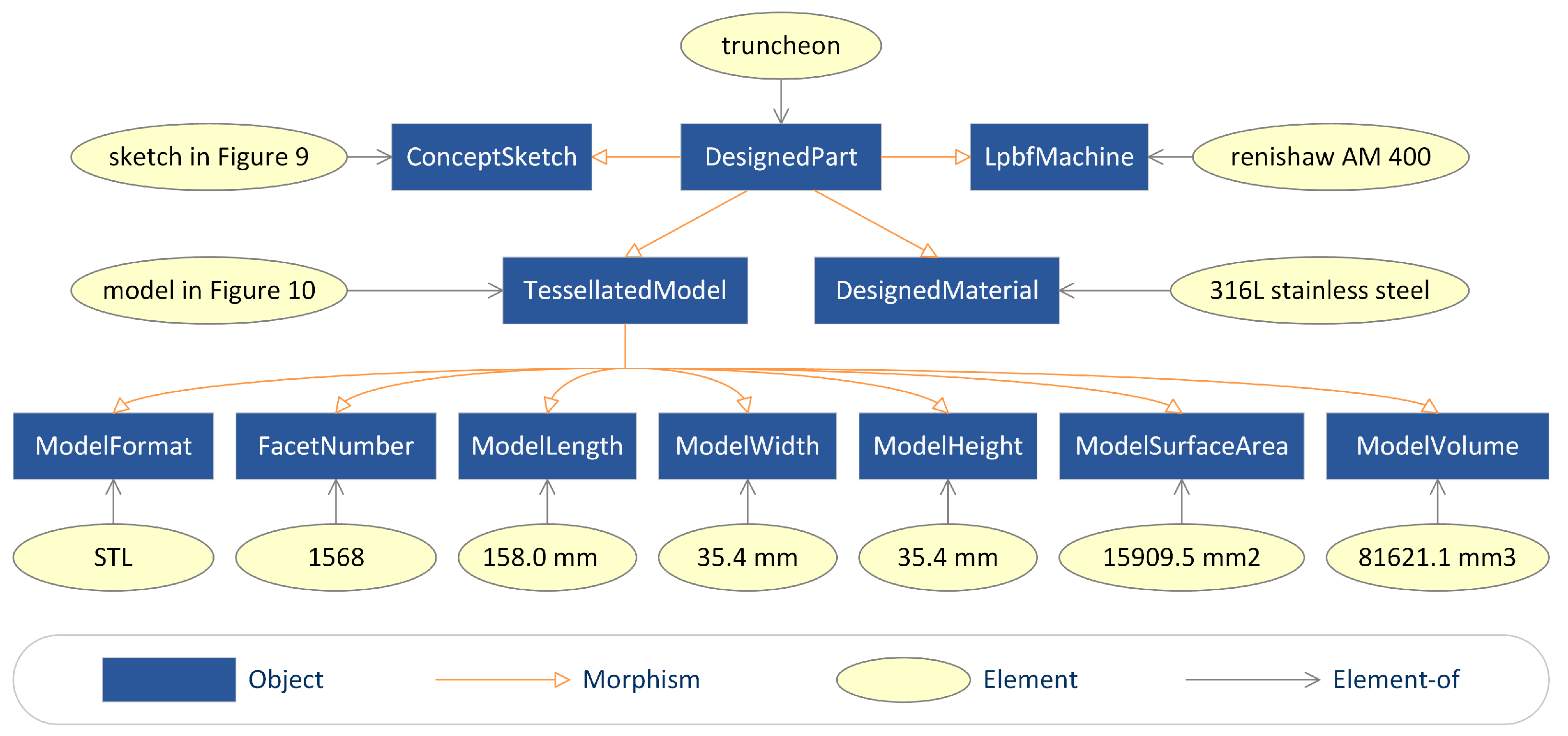
The first step is to represent the data in design. The truncheon was used to study the effect of surface inclinations on the surface texture of an LPBF part. Its concept sketch is shown in Figure 9. A 3D model of the truncheon was created and tessellated in SolidWorks. The tessellated 3D model of the truncheon, as depicted in Figure 10, was encoded in the STL format. It has 1568 triangular facets, a surface area of 15,909.5 mm2, and a volume of 81,621.1 mm3. Its bounding box has a length of 158.0 mm, a width of 35.4 mm, and a height of 35.4 mm. The LPBF machine and material used to build the truncheon were, respectively, Renishaw AM 400 and 316L stainless steel powder supplied by Renishaw. Some information about the machine and some information about the material are listed in Table 1 and Table 2, respectively. Based on these data, twelve elements, as shown in Figure 11, were created in the Design category.
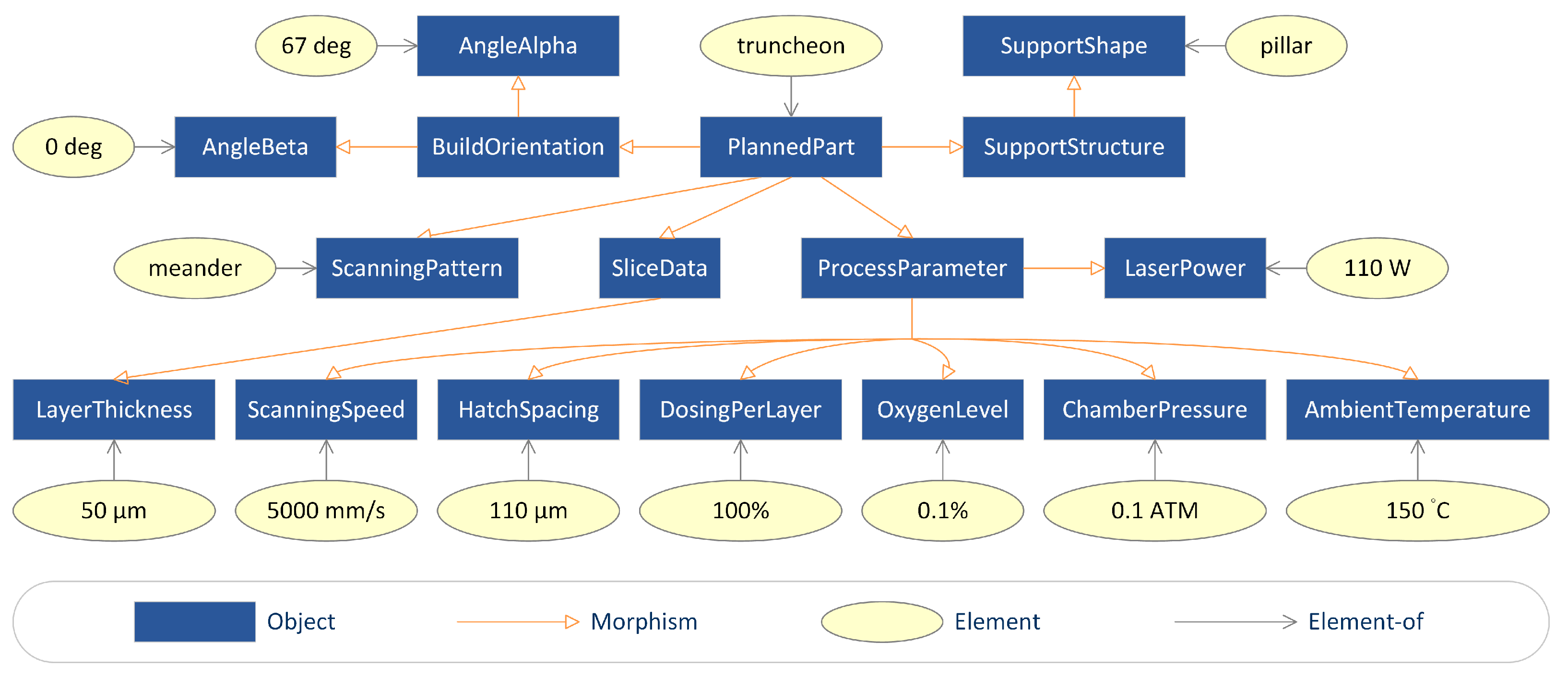
The second step is to represent the data in process planning. The truncheon was built in an orientation whose angle of rotation around the X axis is 67 deg and angle of rotation around the Y axis is 0 deg. The support structure generated for it was a pillar support structure with varying length and 1 mm width. The bottom of the truncheon was supported by the pillar support structure. The build model was sliced with a layer thickness of 50 µm. The selected laser scanning pattern was the meander pattern. The truncheon was built with a laser power of 110 W, a laser scanning speed of 5000 mm/s, a hatch spacing of 110 µm, a dosing per layer of 100%, an oxygen level of 0.1%, a chamber pressure of 0.1 ATM, and an ambient temperature of 150 °C. Based on these data, thirteen elements, as shown in Figure 12, were created in the ProcessPlanning category.
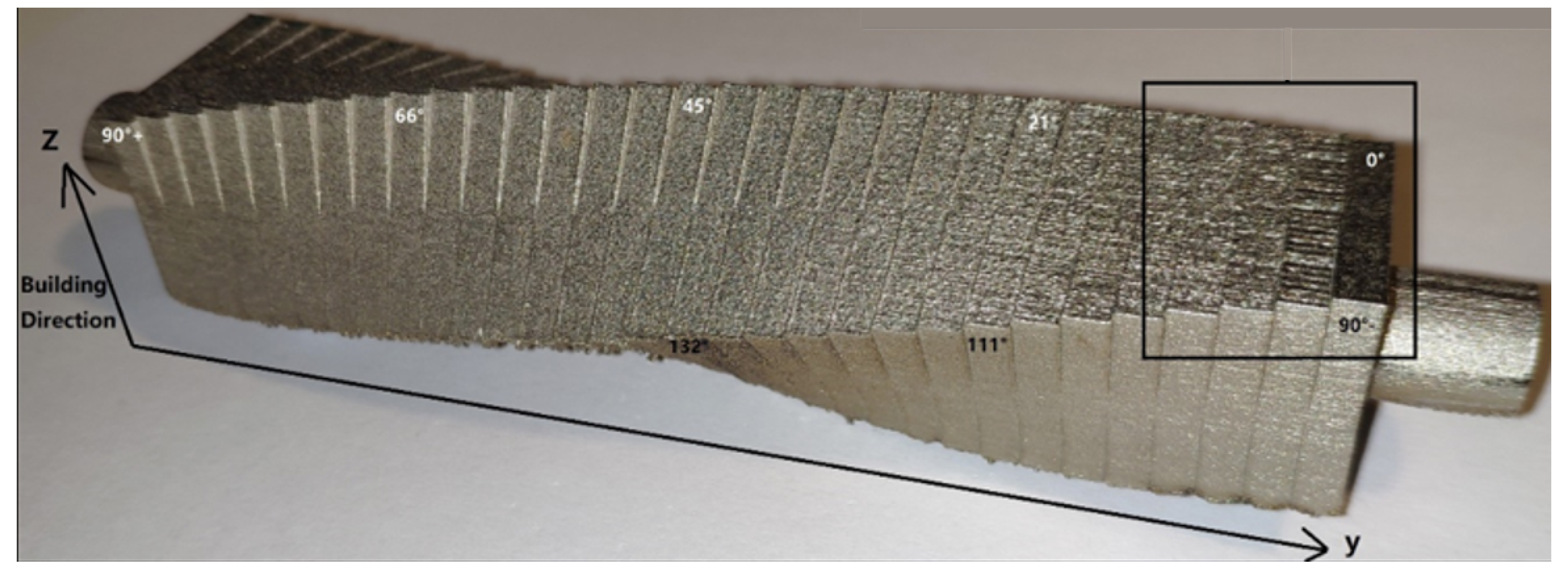
The third step is to represent the data in part build. The truncheon was built with varying inclination angles from 0 deg to 180 deg. A picture of the built truncheon is given in Figure 13. The actual build time and actual build cost are, respectively, 21.8 h and £624.45. Based on these data, three elements, as shown in Figure 14, were created in the PartBuild category.
The fourth step is to represent the data in post-processing. This step was skipped since the built truncheon had not undergone any post-processing.
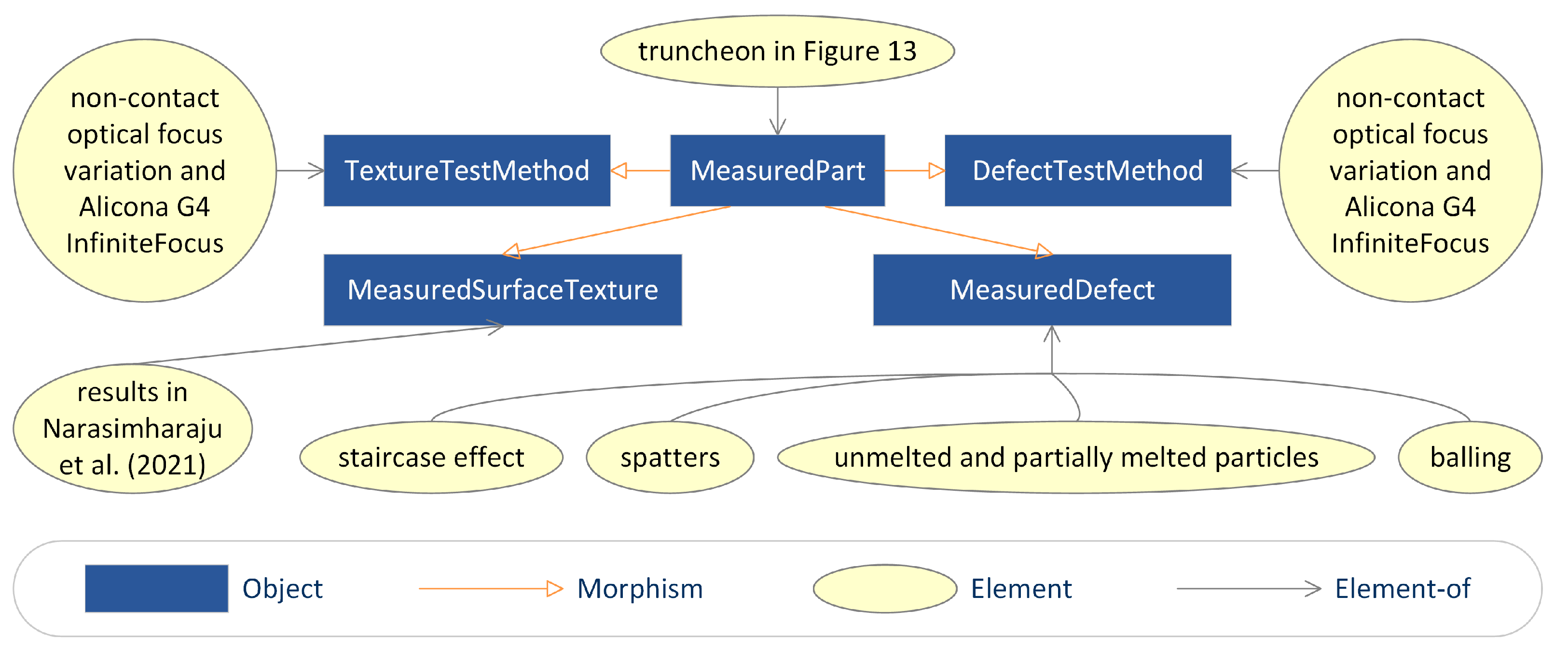
The last step is to represent the data in qualification. The surface texture and defect of the built truncheon were measured using a non-contact optical focus variation method and the Alicona G4 InfiniteFocus system. The configuration of the focus variation measurement is listed in Table 3. The magnification and measurement area were chosen with the goal of capturing the representative fraction of the surfaces, which is appropriate for characterising the staircase effect as well as for the identification and quantification of many particles and spatter formations. The ring light was employed not only to prevent overexposure but also to capture the distinct flank features. After taking measurement readings at three distinct locations for each incremental angle surface, the mean values and standard deviations were calculated. Four repetitions of the measurement at zero degrees were made in order to confirm the repeatability error. The surface texture data were analysed using Digital Surf MountainsMap. The results of the surface texture analysis help to characterise the particle characteristics and staircase effect. Filling the non-measurement spots and, then, least square levelling were the first steps in processing the imported measurement data. After that, the λs filter with a nesting index of 5 μm was used to filter out the short spatial wavelength components, which include measurement noise and fine surface details. Similarly, because of its resilience against outliers, a robust Gaussian filter with a nesting index of 80 μm was used to isolate the characteristics of the particles from the underlying staircase surface. A few non-measured points were observed in optical measurements, mainly due to the shape local surface gradient. These missing points could be filled by the nearest neighbour interpolation. However, the interpolated points are not included in the roughness parameter calculation. The areal surface texture parameters explored in this work are listed in Table 4. The measured parameters was documented in [64]. The measured defects include the staircase effect, spatters, unmelted and partially melted particles, and balling. Based on these data, eight elements, as shown in Figure 15, were created in the Qualification category.

5. Conclusions

In this paper, a semantically enriched LPBF part data model was presented and developed using a CT-based modelling approach. This model consists of a design category, a process planning category, a part build category, a post-processing category, a qualification category, and twenty functors among these categories. The five categories are constructed to represent the data in the five stages of LPBF part realisation process, while the twenty functors are established to communicate the five categories. To demonstrate the developed model, the realisation of an LPBF truncheon was introduced.
In the LPBF part realisation process, a variety of data from heterogeneous sources, such as sketches, 3D models, tessellated 3D models, specifications, process variables, and qualification results, needs to be integrated. Conventional approaches generally have issues with data interoperability and consistency. Category theory can offer a formal framework for modelling these various data sources and their interactions. It can also provide a uniform and consistent method for data integration by describing data as objects and the relationships between them as morphisms. To this end, future work will aim, especially, at studying the practical application of the developed model and extension of the model to data integration and interoperability in LPBF.

Author Contributions

Conceptualisation, Y.Q. and Q.Q.; methodology, Y.Q. and Q.Q.; validation, Y.Q. and S.R.N.; formal analysis, Y.Q.; resources, S.R.N., S.L. and W.Z.; data curation, S.R.N., S.L. and W.Z.; writing—original draft, Y.Q.; visualisation, Y.Q.; supervision, P.J.S. and X.J.; project administration, Q.Q.; funding acquisition, Q.Q., P.J.S. and X.J. All authors have read and agreed to the published version of the manuscript.

Funding

Y.Q. would like to acknowledge the support of the National Natural Science Foundation of China (No. 52105511). Q.Q. would like to acknowledge the support of the EPSRC UKRI Innovation Fellowship (Ref. EP/S001328/1).

Data Availability Statement

Data are contained within the article.

Conflicts of Interest

The authors declare that they have no known competing financial interests or personal relationships that could have appeared to influence the work reported in this paper.

References

  1. Gibson, I.; Rosen, D.; Stucker, B. Additive Manufacturing Technologies: 3D Printing, Rapid Prototyping, and Direct Digital Manufacturing, 2nd ed.; Springer: New York, NY, USA, 2015. [Google Scholar]
  2. Chua, C.K.; Leong, K.F. 3D Printing and Additive Manufacturing: Principles and Applications (The 5th Edition of Rapid Prototyping: Principles and Applications); World Scientific Publishing: Singapore, 2017. [Google Scholar]
  3. Sing, S.L.; Yeong, W.Y. Laser powder bed fusion for metal additive manufacturing: Perspectives on recent developments. Virtual Phys. Prototyp. 2020, 15, 359–370. [Google Scholar] [CrossRef]
  4. Yap, C.Y.; Chua, C.K.; Dong, Z.L.; Liu, Z.H.; Zhang, D.Q.; Loh, L.E.; Sing, S.L. Review of selective laser melting: Materials and applications. Appl. Phys. Rev. 2015, 2, 041101. [Google Scholar] [CrossRef]
  5. Gu, D.; Shi, X.; Poprawe, R.; Bourell, D.L.; Setchi, R.; Zhu, J. Material-structure-performance integrated laser-metal additive manufacturing. Science 2021, 372. [Google Scholar] [CrossRef] [PubMed]
  6. Dowling, L.; Kennedy, J.; O’shaughnessy, S.; Trimble, D. A review of critical repeatability and reproducibility issues in powder bed fusion. Mater. Des. 2020, 186, 108346. [Google Scholar] [CrossRef]
  7. Kim, D.B.; Witherell, P.; Lipman, R.; Feng, S.C. Streamlining the additive manufacturing digital spectrum: A systems approach. Addit. Manuf. 2015, 5, 20–30. [Google Scholar] [CrossRef]
  8. Mies, D.; Marsden, W.; Warde, S. Overview of Additive Manufacturing Informatics: “A Digital Thread”. Integr. Mater. Manuf. Innov. 2016, 5, 114–142. [Google Scholar] [CrossRef]
  9. Kim, D.B.; Witherell, P.; Lu, Y.; Feng, S. Toward a Digital Thread and Data Package for Metals-Additive Manufacturing. Smart Sustain. Manuf. Syst. 2017, 1, 75–99. [Google Scholar] [CrossRef]
  10. Qin, Y.; Qi, Q.; Scott, P.J.; Jiang, X. Status, comparison, and future of the representations of additive manufacturing data. Comput.-Aided Des. 2019, 111, 44–64. [Google Scholar] [CrossRef]
  11. Bonnard, R.; Hascoët, J.Y.; Mognol, P. Data model for additive manufacturing digital thread: State of the art and perspectives. Int. J. Comput. Integr. Manuf. 2019, 32, 1170–1191. [Google Scholar] [CrossRef]
  12. Kumar, V.; Dutta, D. An approach to modeling & representation of heterogeneous objects. J. Mech. Des. 1998, 120, 659–667. [Google Scholar]
  13. Kou, X.Y.; Tan, S.T. A hierarchical representation for heterogeneous object modeling. Comput.-Aided Des. 2005, 37, 307–319. [Google Scholar] [CrossRef]
  14. Kou, X.Y.; Tan, S.T.; Sze, W.S. Modeling complex heterogeneous objects with non-manifold heterogeneous cells. Comput.-Aided Des. 2006, 38, 457–474. [Google Scholar] [CrossRef]
  15. Ingole, D.; Kuthe, A.; Deshmukh, T.; Bansod, S. Coding system for rapid prototyping industry. Rapid Prototyp. J. 2008, 14, 221–233. [Google Scholar] [CrossRef]
  16. Ko, H.; Moon, S.K.; Otto, K.N. Design knowledge representation to support personalised additive manufacturing. Virtual Phys. Prototyp. 2015, 10, 217–226. [Google Scholar] [CrossRef]
  17. Lu, Y.; Choi, S.; Witherell, P. Towards an Integrated Data Schema Design for Additive Manufacturing: Conceptual Modeling. In Proceedings of the International Design Engineering Technical Conferences and Computers and Information in Engineering Conference, Boston, MA, USA, 2–5 August 2015; American Society of Mechanical Engineers: New York, NY, USA, 2015; Volume 57045, p. V01AT02A032. [Google Scholar]
  18. Prater, T. Database development for additive manufacturing. Prog. Addit. Manuf. 2017, 2, 11–18. [Google Scholar] [CrossRef]
  19. Feng, S.C.; Witherell, P.; Ameta, G.; Kim, D.B. Activity model for homogenization of data sets in laser-based powder bed fusion. Rapid Prototyp. J. 2017, 23, 137–148. [Google Scholar] [CrossRef]
  20. Wang, Y.; Blache, R.; Zheng, P.; Xu, X. A Knowledge Management System to Support Design for Additive Manufacturing Using Bayesian Networks. J. Mech. Des. 2018, 140, 051701. [Google Scholar] [CrossRef]
  21. Bonnard, R.; Hascoët, J.Y.; Mognol, P.; Zancul, E.; Alvares, A.J. Hierarchical object-oriented model (HOOM) for additive manufacturing digital thread. J. Manuf. Syst. 2019, 50, 36–52. [Google Scholar] [CrossRef]
  22. Liu, C.; Le Roux, L.; Körner, C.; Tabaste, O.; Lacan, F.; Bigot, S. Digital Twin-enabled Collaborative Data Management for Metal Additive Manufacturing Systems. J. Manuf. Syst. 2022, 62, 857–874. [Google Scholar] [CrossRef]
  23. Barbau, R.; Krima, S.; Rachuri, S.; Narayanan, A.; Fiorentini, X.; Foufou, S.; Sriram, R.D. OntoSTEP: Enriching product model data using ontologies. Comput.-Aided Des. 2012, 44, 575–590. [Google Scholar] [CrossRef]
  24. Liu, X.; Rosen, D.W. Ontology Based Knowledge Modeling and Reuse Approach of Supporting Process Planning in Layer-Based Additive Manufacturing. In Proceedings of the 2010 International Conference on Manufacturing Automation, IEEE, Hong Kong, China, 13–15 December 2010; pp. 261–266. [Google Scholar]
  25. Witherell, P.; Feng, S.; Simpson, T.W.; Saint John, D.B.; Michaleris, P.; Liu, Z.K.; Chen, L.Q.; Martukanitz, R. Toward Metamodels for Composable and Reusable Additive Manufacturing Process Models. J. Manuf. Sci. Eng. 2014, 136, 061025. [Google Scholar] [CrossRef]
  26. Roh, B.M.; Kumara, S.R.; Simpson, T.W.; Michaleris, P.; Witherell, P.; Assouroko, I. Ontology-Based Laser and Thermal Metamodels for Metal-Based Additive Manufacturing. In Proceedings of the International Design Engineering Technical Conferences and Computers and Information in Engineering Conference, Charlotte, NC, USA, 21–24 August 2016; American Society of Mechanical Engineers: New York, NY, USA, 2016; Volume 50077, p. V01AT02A043. [Google Scholar]
  27. Lu, Y.; Witherell, P.; Lopez, F.; Assouroko, I. Digital Solutions for Integrated and Collaborative Additive Manufacturing. In Proceedings of the International Design Engineering Technical Conferences and Computers and Information in Engineering Conference, Charlotte, NC, USA, 21–24 August 2016; American Society of Mechanical Engineers: New York, NY, USA, 2016; Volume 50084, p. V01BT02A033. [Google Scholar]
  28. Dinar, M.; Rosen, D.W. A Design for Additive Manufacturing Ontology. J. Comput. Inf. Sci. Eng. 2017, 17, 021013. [Google Scholar] [CrossRef]
  29. Hagedorn, T.J.; Krishnamurty, S.; Grosse, I.R. A Knowledge-Based Method for Innovative Design for Additive Manufacturing Supported by Modular Ontologies. J. Comput. Inf. Sci. Eng. 2018, 18, 021009. [Google Scholar] [CrossRef]
  30. Liang, J.S. An ontology-oriented knowledge methodology for process planning in additive layer manufacturing. Robot. Comput.-Integr. Manuf. 2018, 53, 28–44. [Google Scholar] [CrossRef]
  31. Kim, S.; Rosen, D.W.; Witherell, P.; Ko, H. A Design for Additive Manufacturing Ontology to Support Manufacturability Analysis. J. Comput. Inf. Sci. Eng. 2019, 19, 041014. [Google Scholar] [CrossRef]
  32. Sanfilippo, E.M.; Belkadi, F.; Bernard, A. Ontology-based knowledge representation for additive manufacturing. Comput. Ind. 2019, 109, 182–194. [Google Scholar] [CrossRef]
  33. Ali, M.M.; Rai, R.; Otte, J.N.; Smith, B. A product life cycle ontology for additive manufacturing. Comput. Ind. 2019, 105, 191–203. [Google Scholar]
  34. Xiong, Y.; Dharmawan, A.G.; Tang, Y.; Foong, S.; Soh, G.S.; Rosen, D.W. A knowledge-based process planning framework for wire arc additive manufacturing. Adv. Eng. Inform. 2020, 45, 101135. [Google Scholar] [CrossRef]
  35. Ko, H.; Witherell, P.; Lu, Y.; Kim, S.; Rosen, D.W. Machine learning and knowledge graph based design rule construction for additive manufacturing. Addit. Manuf. 2021, 37, 101620. [Google Scholar] [CrossRef]
  36. Chen, R.; Lu, Y.; Witherell, P.; Simpson, T.W.; Kumara, S.; Yang, H. Ontology-Driven Learning of Bayesian Network for Causal Inference and Quality Assurance in Additive Manufacturing. IEEE Robot. Autom. Lett. 2021, 6, 6032–6038. [Google Scholar] [CrossRef]
  37. Roh, B.M.; Kumara, S.R.; Witherell, P.; Simpson, T.W. Ontology-based process map for metal additive manufacturing. J. Mater. Eng. Perform. 2021, 30, 8784–8797. [Google Scholar] [CrossRef]
  38. Mayerhofer, M.; Lepuschitz, W.; Hoebert, T.; Merdan, M.; Schwentenwein, M.; Strasser, T.I. Knowledge-Driven Manufacturability Analysis for Additive Manufacturing. IEEE Open J. Ind. Electron. Soc. 2021, 2, 207–223. [Google Scholar] [CrossRef]
  39. Li, Z.; Huang, M.; Zhong, Y.; Qin, Y. A Description Logic Based Ontology for Knowledge Representation in Process Planning for Laser Powder Bed Fusion. Appl. Sci. 2022, 12, 4612. [Google Scholar] [CrossRef]
  40. Roh, B.M.; Kumara, S.R.T.; Yang, H.; Simpson, T.W.; Witherell, P.; Jones, A.T.; Lu, Y. Ontology network-based in-situ sensor selection for quality management in metal additive manufacturing. J. Comput. Inf. Sci. Eng. 2022, 22, 060905. [Google Scholar] [CrossRef]
  41. Hasan, N.; Rahman, M.H.; Wessman, A.; Smith, T.; Shafae, M. Process Defects Knowledge Modeling in Laser Powder Bed Fusion Additive Manufacturing: An Ontological Framework. Manuf. Lett. 2023, 35, 822–833. [Google Scholar] [CrossRef]
  42. Park, H.; Ko, H.; Lee, Y.t.T.; Feng, S.; Witherell, P.; Cho, H. Collaborative knowledge management to identify data analytics opportunities in additive manufacturing. J. Intell. Manuf. 2023, 34, 541–564. [Google Scholar] [CrossRef]
  43. Wang, R.; Cheung, C.F. Knowledge graph embedding learning system for defect diagnosis in additive manufacturing. Comput. Ind. 2023, 149, 103912. [Google Scholar] [CrossRef]
  44. Wang, Y.; Peng, T.; Xiong, Y.; Kim, S.; Zhu, Y.; Tang, R. An ontology of eco-design for additive manufacturing with informative sustainability analysis. Adv. Eng. Inform. 2024, 60, 102430. [Google Scholar] [CrossRef]
  45. Eilenberg, S.; MacLane, S. General Theory of Natural Equivalences. Trans. Am. Math. Soc. 1945, 58, 231–294. [Google Scholar] [CrossRef]
  46. Spivak, D.I. Category Theory for the Sciences; MIT Press: Cambridge, MA, USA, 2014. [Google Scholar]
  47. Qi, Q.; Pagani, L.; Jiang, X.; Scott, P.J. Enabling metrology-oriented specification of geometrical variability—A categorical approach. Adv. Eng. Inform. 2019, 39, 347–358. [Google Scholar] [CrossRef]
  48. Spivak, D.I.; Kent, R.E. Ologs: A Categorical Framework for Knowledge Representation. PLoS ONE 2012, 7, e24274. [Google Scholar] [CrossRef] [PubMed]
  49. Baez, J.C.; Fong, B. A compositional framework for passive linear networks. Theory Appl. Categ. 2018, 33, 1158–1222. [Google Scholar]
  50. Brown, K.S.; Spivak, D.I.; Wisnesky, R. Categorical data integration for computational science. Comput. Mater. Sci. 2019, 164, 127–132. [Google Scholar] [CrossRef]
  51. Baez, J.C.; Master, J. Open petri nets. Math. Struct. Comput. Sci. 2020, 30, 314–341. [Google Scholar] [CrossRef]
  52. Bakirtzis, G.; Fleming, C.H.; Vasilakopoulou, C. Categorical Semantics of Cyber-Physical Systems Theory. ACM Trans. Cyber-Phys. Syst. 2021, 5, 1–32. [Google Scholar] [CrossRef]
  53. Aguinaldo, A.; Bunker, J.; Pollard, B.; Shukla, A.; Canedo, A.; Quiros, G.; Regli, W. RoboCat: A Category Theoretic Framework for Robotic Interoperability Using Goal-Oriented Programming. IEEE Trans. Autom. Sci. Eng. 2021, 19, 2637–2645. [Google Scholar] [CrossRef]
  54. Rosen, D.W.; Seepersad, C.C.; Simpson, T.W.; Williams, C.B. Design for Additive Manufacturing: A Paradigm Shift in Design, Fabrication, and Qualification. J. Mech. Des. 2015, 137, 110301. [Google Scholar] [CrossRef]
  55. Williams, C.B.; Mistree, F.; Rosen, D.W. A Functional Classification Framework for the Conceptual Design of Additive Manufacturing Technologies. J. Mech. Des. 2011, 133, 121002. [Google Scholar] [CrossRef]
  56. Thompson, M.K.; Moroni, G.; Vaneker, T.; Fadel, G.; Campbell, R.I.; Gibson, I.; Bernard, A.; Schulz, J.; Graf, P.; Ahuja, B.; et al. Design for Additive Manufacturing: Trends, opportunities, considerations, and constraints. CIRP Ann. 2016, 65, 737–760. [Google Scholar] [CrossRef]
  57. Qin, Y.; Qi, Q.; Shi, P.; Scott, P.J.; Jiang, X. Status, issues, and future of computer-aided part orientation for additive manufacturing. Int. J. Adv. Manuf. Technol. 2021, 115, 1295–1328. [Google Scholar] [CrossRef]
  58. Jiang, J.; Xu, X.; Stringer, J. Support Structures for Additive Manufacturing: A Review. J. Manuf. Mater. Process. 2018, 2, 64. [Google Scholar] [CrossRef]
  59. Zhao, D.; Guo, W. Shape and Performance Controlled Advanced Design for Additive Manufacturing: A Review of Slicing and Path Planning. J. Manuf. Sci. Eng. 2020, 142, 010801. [Google Scholar] [CrossRef]
  60. Jia, H.; Sun, H.; Wang, H.; Wu, Y.; Wang, H. Scanning strategy in selective laser melting (SLM): A review. Int. J. Adv. Manuf. Technol. 2021, 113, 2413–2435. [Google Scholar] [CrossRef]
  61. Townsend, A.; Senin, N.; Blunt, L.; Leach, R.K.; Taylor, J.S. Surface texture metrology for metal additive manufacturing: A review. Precis. Eng. 2016, 46, 34–47. [Google Scholar] [CrossRef]
  62. ISO/ASTM 52904; Additive manufacturing—Process Characteristics and Performance—Practice for Metal Powder Bed Fusion Process to Meet Critical Applications. International Organization for Standardization: Geneva, Switzerland, 2019.
  63. ISO/ASTM 52927; Additive Manufacturing—General Principles—Main Characteristics and Corresponding Test Methods. International Organization for Standardization: Geneva, Switzerland, 2024.
  64. Narasimharaju, S.R.; Liu, W.; Zeng, W.; See, T.L.; Scott, P.; Jiang, X.J.; Lou, S. Surface Texture Characterization of Metal Selective Laser Melted Part With Varying Surface Inclinations. J. Tribol. 2021, 143, 051106. [Google Scholar] [CrossRef]
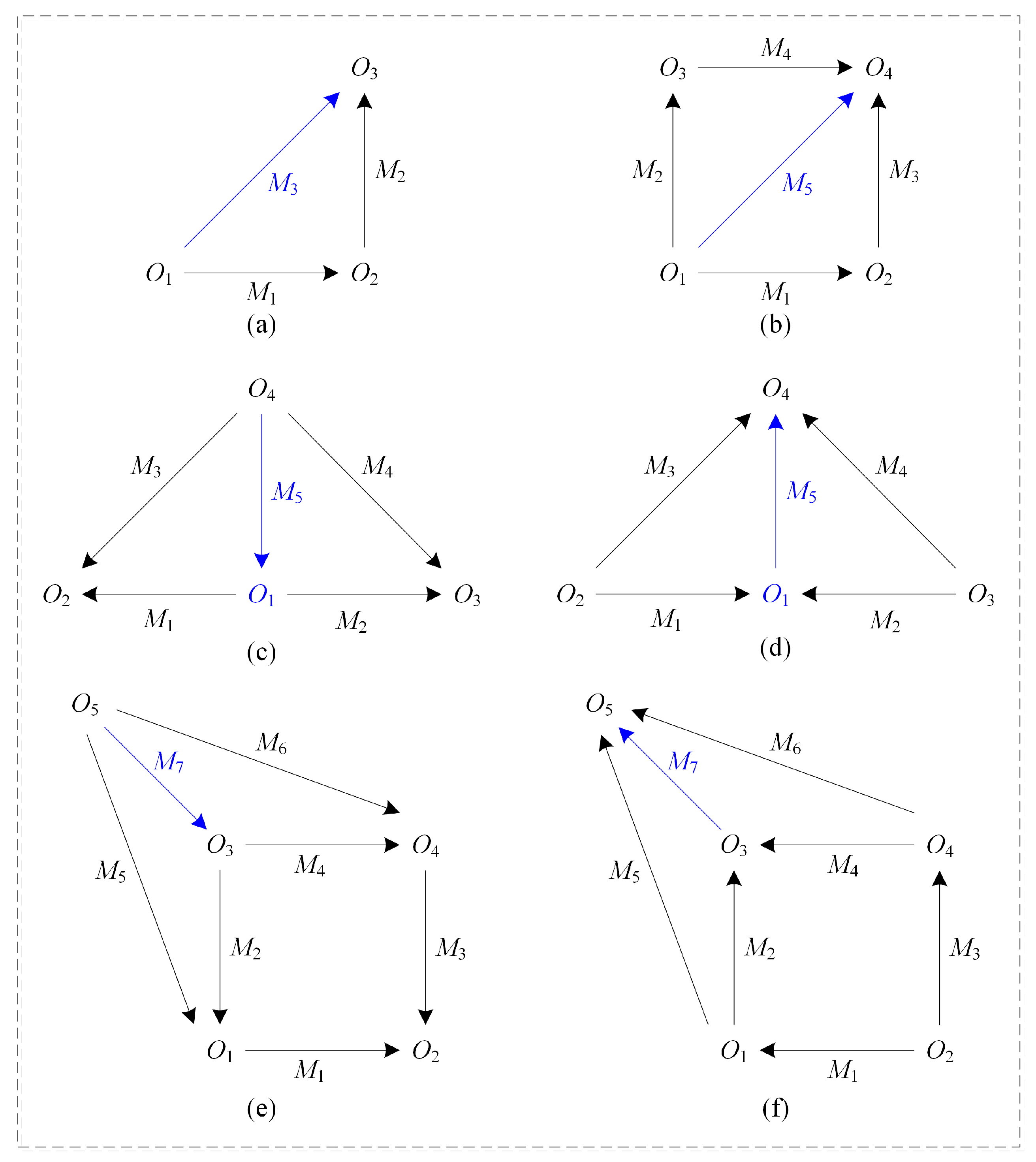
Figure 1. Six inherent morphism structures. (a) Triangle; (b) Rectangle; (c) Product; (d) Coproduct; (e) Pullback; (f) Pushout.
Jmmp 08 00130 g001
Figure 2. Overall structure of the semantically enriched model.
Jmmp 08 00130 g002
Figure 3. Objects and morphisms in the Design category.
Jmmp 08 00130 g003
Figure 4. Objects and morphisms in the ProcessPlanning category.
Jmmp 08 00130 g004
Figure 5. Objects and morphisms in the PartBuild category.
Jmmp 08 00130 g005
Figure 6. Objects and morphisms in the PostProcessing category.
Jmmp 08 00130 g006
Figure 7. Objects and morphisms in the Qualification category.
Jmmp 08 00130 g007
Figure 8. A partial visual representation of the developed model.
Jmmp 08 00130 g008
Figure 9. Concept sketch of a truncheon.
Jmmp 08 00130 g009
Figure 10. Tessellated 3D model of a truncheon.
Jmmp 08 00130 g010
Figure 11. Representation of the data related to the truncheon in design. Sketch is in Figure 9. Model is in Figure 10.
Jmmp 08 00130 g011
Figure 12. Representation of the data related to the truncheon in process planning.
Jmmp 08 00130 g012
Figure 13. A truncheon built using Renishaw AM 400 and 316L stainless steel.
Jmmp 08 00130 g013
Figure 14. Representation of the data related to the truncheon in part build. Truncheon is in Figure 13.
Jmmp 08 00130 g014
Figure 15. Representation of the data related to the truncheon in qualification. Truncheon is in Figure 13. Narasimharaju et al. (2021) corresponds to [64].
Jmmp 08 00130 g015
Table 1. Some information about the machine used (Renishaw AM 400).
Laser TypeLaser WavelengthMaximum PowerBuild Area Dimension
Pulsed Nd:YAG1070 nm400 W250 × 250 × 300 mm
Table 2. Some information about the material used (316 L).
Powder SizeFeCrNiMoMn
15–45 μ mBalance16–18%10–14%2–3%≤2%
SiNOPCS
≤1%≤0.1%≤0.1%≤0.045%≤0.03%≤0.03%
Table 3. Configuration of the focus variation measurement.
MagnificationIlluminationLateral
Resolution
Vertical
Resolution
Sampling
Distance
Measurement
Dimension
20×Ring light1 μ m0.7 μ m0.878 μ m2.59 × 2.36 mm
Table 4. Areal surface texture parameters explored in this work.
CategoryParameterMeaning
Height S a ( μ m)Arithmetical mean height of the scale-limited surface
S q ( μ m)Root mean square height of the scale-limited surface
S s k Skewness of the scale-limited surface
S k u Kurtosis of the scale-limited surface
Hybrid S d q Root mean square gradient of the scale-limited surface
S d r (%)Developed interfacial area ratio of the scale-limited surface
Functional S m r 1 (%)Material ratio related to the peak zone
V m p (mm3/mm2)Peak material volume of the scale-limited surface
Spatial S a l ( μ m)Autocorrelation length (fastest decay to 0.2)
S t r Texture aspect ratio
Feature S p d (1/mm2)Density of peaks (number of peaks per unit area)
Disclaimer/Publisher’s Note: The statements, opinions and data contained in all publications are solely those of the individual author(s) and contributor(s) and not of MDPI and/or the editor(s). MDPI and/or the editor(s) disclaim responsibility for any injury to people or property resulting from any ideas, methods, instructions or products referred to in the content.