Abstract
Surface modification through electrical discharge machining (EDM) results in many advantages, such as improved surface hardness, enhanced wear resistance, and better micro-structuring. During EDM-based surface modification, either the eroding tool electrode or a powder-mixed dielectric can be utilized to add material onto the machined surface of the workpiece. The current study looks at the surface modification of H13 die steel using EDM in a dielectric medium mixed with graphite powder. The experiments were carried out using a Taguchi experimental design. In this work, peak current, pulse-on time, and powder concentration are taken into consideration as input factors. Tool wear rate (TWR), material removal rate (MRR), and the microhardness of the surface of the machined specimen are taken as output parameters. The machined surface’s microhardness was found to have improved by 159%. The results of X-ray diffraction (XRD) and energy dispersive X-ray spectroscopy (EDS) analysis and changes in MRR and TWR due to the powder-mixed dielectric are also discussed in detail.
1. Introduction
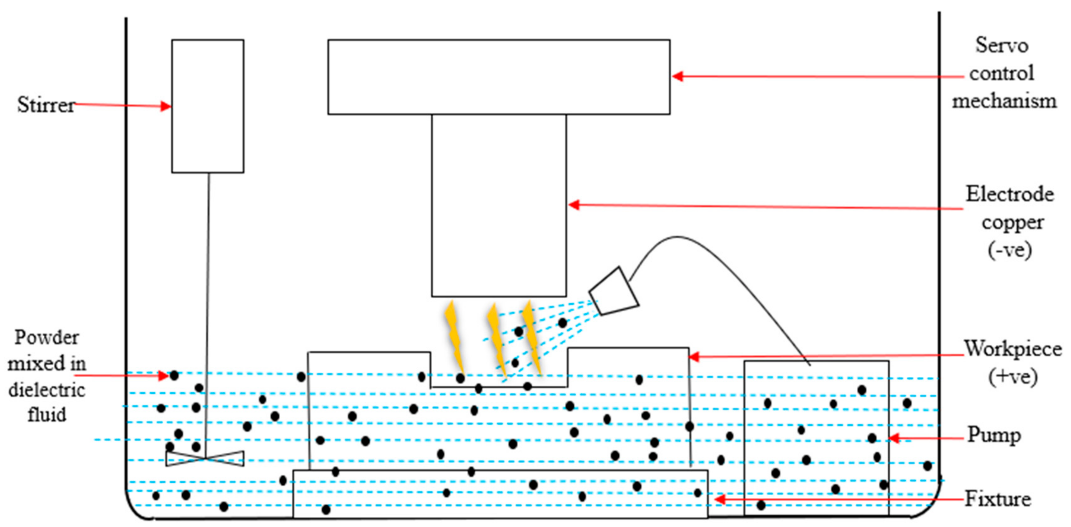
An unconventional method known as EDM is utilized to cut and shape hard materials. This approach removes material from the workpiece’s surface by creating a spark deep within the dielectric fluid between the electrode and the workpiece. The smallest space between the electrode and the workpiece is where sparks are generated, raising the temperature surrounding it to 8000–12,000 °C, causing the material to vaporize and erode. With the aid of a hydraulic pump, the removed material is cleaned from the workpiece’s surface using the dielectric oil. Additionally, the tool’s material is also eroded by this process, shortening its lifespan. Enhancing the EDM process is achieved by introducing different powders into the dielectric fluid. The powder improves MRR and TWR and aids in the surface modification of workpieces (Figure 1).
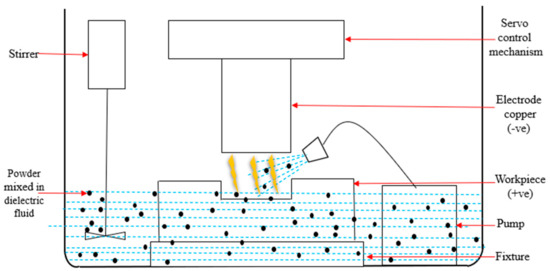
Figure 1.
The setup of powder-mixed electric discharge machining.
Researchers have conducted experimental work on H13 die steel using different powders composed of materials such as copper, silver, tungsten carbide, and tungsten. Jeswani studied the effect of graphite (Gr) powder mixed with kerosene oil in EDM [1]. The findings indicated that the inclusion of Gr powder (10 µm) in the kerosene oil enhanced MRR by 60% and increased TWR by 15% during EDM.
Wong et al. used various EDM powders to investigate the near-mirror finish phenomenon and found that mixing aluminum (Al) powder into the dielectric oil produced the best mirror finish for SKH-51 workpieces compared to silicon (Si) and carbon (C) powders [2]. The combination of powder material and workpiece material needs to be optimal to achieve the maximum mirror finish on the workpiece.
Fong et al. examined the surface characteristics of SKD-11 using powder-mixed EDM; their investigation showed that Al powder provided the most superior surface finish in contrast to the powders of copper, silicon carbide, and chromium [3]. A powder particle size of 70–80 nm gave the best surface roughness compared to particle sizes of 10–15 µm and 100 µm. Among the powders tested, Al powder also reduced the recast layer more effectively than copper, chromium, and silicon carbide powders. During their investigation into the effects of silicon powder combined with dielectric fluid in EDM, Pecas et al. discovered that adding 2 gm/L of silicon powder to the dielectric fluid improved the efficiency of the polishing process [4], resulting in a smoother surface and more reflective craters. The size of the area affects the surface roughness, which ranges from 0.09 µm for 1 cm2 to 0.57 µm for 64 cm2.
Wu et al. used EDM with a surfactant and aluminum-added dielectric to study the surface finishing of SKD steel [5]. The machining parameters utilized in this experiment were a powder concentration of 0.1 gm/L, a peak current of 0.3 A, a peak time of 1.5 µs, positive polarity, and a surfactant concentration of 0.25 gm/L. The findings indicate that adding Al powder to the dielectric oil can significantly reduce its insulation properties, increasing the gap distance between the workpiece and electrodes. Furthermore, the surface roughness of SKD steel is improved by up to 60%.
The effect of Si powder-mixed EDM on the machining rate of AISI D2 die steel was investigated by Kansal et al. [6]. The results indicate that the optimal machining parameters for material removal from AISI D2 are a peak current of 16 A, a pulse-on duration of 100 µs, a powder concentration of 4 gm/L, and a gain of 1 mm/s.
Kumar et al. reviewed surface modification by EDM and revealed that various research studies have acknowledged the impact of peak current; but no prior research was performed on the variation in pulse-on and pulse-off times [7]. Most research on powder-mixed electrical discharge machining (PMEDM) has shown the impact of output parameters with normal polarity (negative electrode), such as surface roughness, MRR, and TWR.
Khan et al. studied the use of powder-based EDM for surface modification, investigating the impact of using kerosene as a dielectric fluid with powdered TiC and Al2O3 over mild steel [8]. A copper–tungsten (30–70%) tool was used in the EDM process. Copper, tungsten (from the electrode), aluminum, and carbon were detected by EDS analysis on the machined surface of mild steel. The best surface hardness values were found when TiC powder outperformed Al2O3 powder combined with the dielectric fluid. Conversely, Al2O3 powder produced the thickest recast layer.
Using powder-mixed EDM, Batish et al. investigated the material transfer process in die steels, wherein high Carbon High Chromium (HCHCr), H11, and EN31 die steels were used as workpiece materials with a graphite powder-mixed dielectric fluid and a W-Cu electrode [9]. Results show that copper tools are most effective when used with EN31 and H11 die steel; on the other hand, for HCHCr steel, W-Cu electrodes outperformed copper electrodes. The addition of graphite powder boosts the microhardness of all three materials by 80%.
Kumar et al. investigated the use of tungsten powder in the dielectric fluid during the EDM process to modify the surface of die steel materials [10]. The findings reveal that the small amount of tungsten and carbon found on the surface of all three work materials significantly affects their properties. The microhardness of all three work materials (H13 die steel, ONHS, and D2 die steel) showed a significant increase of over 100%.
Hu et al. used powder-mixed EDM to investigate the SiCp/Al composite’s surface characteristics [11]. The workpieces made of SiCp/Al material and ASP-23 alloy steel were immersed in a dielectric fluid containing 35 gm/L of Al powder. The experiment revealed that roughness was reduced by about 31.5%, along with an increase in Si and C contents on the surface of the workpiece. Wear resistance increased by roughly 100% and hardness by 40%.
Marashi et al. examined the surface characteristics in EDM of AISI D2 steel by adding Ti nanopowder to the dielectric fluid [12]. The results indicate that surface roughness and MRR increased across all machining conditions except for the discharge duration of 340 µs. Adding Ti nanopowder to the dielectric oil resulted in the greatest enhancement at a Ton of 210 µs, with the average surface roughness and MRR showing the most improvement at 35% and 69% at peak currents of 12 A and 6 A, respectively.
Joshi et al. reviewed powder-mixed EDM [13]. This review analysis shows that powder-mixed EDM represents an enhanced version of EDM, with the inclusion of powder in the dielectric fluid playing a crucial role in enhancing MRR and reducing TWR compared to the powderless EDM process. Moreover, powder-mixed dielectric aids in achieving altered surface properties and a mirror-like surface finish.
Kumar et al. examined the effectiveness of materials modified by EDM [14]. It has been discovered that adding powder to the dielectric fluid improves the surface characteristics and machining. The powder, when combined with the dielectric fluid, can be found on the molten surface of the workpiece as it undergoes the machining process. Surface modification with EDM improves output parameters such as wear resistance, surface finish, and microhardness of the material.
Sharma et al. studied the surface modification of biodegradable Mg-4Zn alloys using PMEDM [15]. The process parameters were optimized using Gray Relational Analysis after conducting an experiment based on the mixed design L18 orthogonal array Taguchi. Zr powder improved MRR, the thickness of the alloyed layer (TAL), and lowered the surface roughness (SR) compared to Mn powder. The maximum MRR was attained at a powder concentration of 4 gm/L. Conversely, the greatest TAL value on the machined surface was obtained at a powder concentration of 6 gm/L. MRR and SR increased with increasing values of peak current and Ton.
The application of nano-graphene powder and aluminum oxide (Al2O3) in the EDM of titanium alloy was studied by Chaudhari et al. [16]. A single-objective optimization achieved a material removal rate (MRR) of 10.7071 mm3/s and a surface roughness (SR) of 4.41 µm. Alumina powder was added to the dielectric fluid, increasing the SR and MRR by 18.27% and 35.19%, respectively. In contrast, the utilization of nano-graphene powder mixed with the dielectric fluid exhibited greater improvements in MRR and SR by 45.81% and 37.22%, respectively. This notable improvement is explained by the greater conductivity of the powdered nano-graphene.
According to the published literature, the surface modification of H13 die steel through EDM using graphite powder of size 400 mesh has not been investigated for output parameters including MRR, TWR, and microhardness simultaneously. To address this gap in the literature, the present work aims at detailed investigations of EDM-based processing of H13 die steel with powder concentrations of 2, 4, and 6 gm/L; peak currents of 2, 4, and 6 A; and pulse-on times of 15, 30, and 75 µs. MRR and TWR are important from a manufacturing point of view, while microhardness measurements are important from a design perspective. High microhardness leads to better surface wear properties, which are related to product life and design. The effects of EDM process parameters on the structural composition of the material have been further investigated using the results of EDS and XRD. The percentage increases in MRR, TWR, and microhardness using PMEDM compared to powderless EDM for H13 die steel have been investigated in detail.
2. Experimental Setup
The purpose of the experiments was to investigate the surface modification of H13 die steel on an EDM machine (Elektra Plus RT-20 Model: EMS 5535: India). The hardening of H13 die steel typically involves heating H13 steel components uniformly to a temperature between 990 °C and 1020 °C. Subsequently, to achieve the highest level of hardness and desired microstructure, the heated H13 die steel was rapidly cooled by quenching it in oil. The surface chemical composition of the H13 die steel specimen before machining is shown in Table 1, as determined using EDS.

Table 1.
Surface chemical composition of the specimen before machining.
The H13 die steel was initially shaped into a cylindrical form measuring 5 mm in height and 28 mm in diameter. Subsequently, the H13 die steel rod was sliced into 14 pieces, each measuring 7 mm in length, using a slitting cutter machine. These pieces were then ground on both faces by a grinding machine to create perfectly cylindrical pieces, each measuring 5 mm in height.
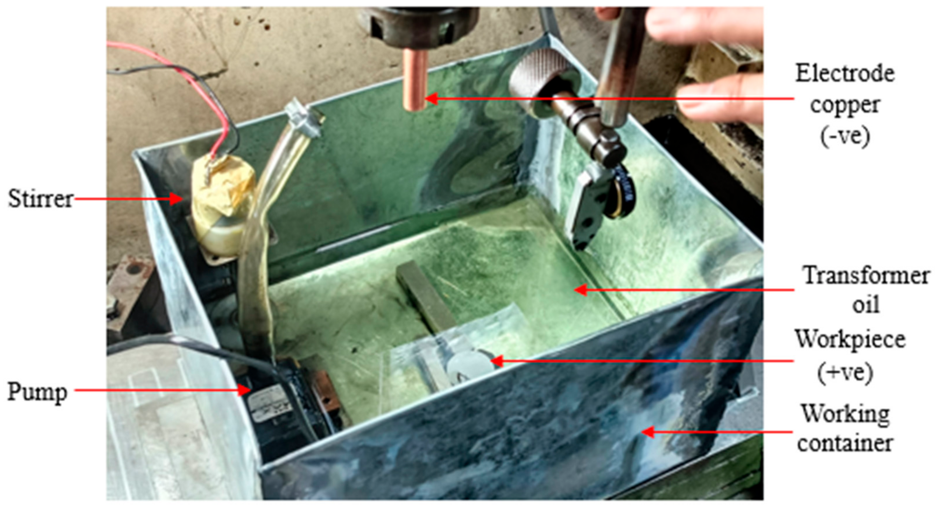
The microhardness of one specimen was measured before machining using the Vickers Microhardness testing apparatus. For the experiment, a galvanized steel sheet container tank with a low-capacity water pump and a stirrer was utilized. The workpiece was securely held in place by a tiny magnet acting as a fixture (refer to Figure 2).
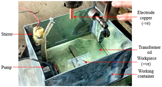
Figure 2.
Electrical discharge machine used in the research.
In PMEDM, machine settings play a crucial role as they directly influence the machining process and its outcomes. Table 2 presents the machine parameters employed in these studies. The pulse-off time is multiplied by 1.5 to determine the pulse-on time, which is directly associated with it.

Table 2.
Machining parameters.
To examine the MRR, TWR, and microhardness of H13 die steel with PMEDM, three experiments were conducted without powder.
In these experiments, two machining factors were considered: pulse-on time (15, 30, 75 µs) and peak current (2, 4, 6 A).
To improve the rate of material removal and microhardness for H13 die steel, graphite powder was combined with transformer oil. A 99% pure graphite powder with a grain size of 400 mesh (37 µm) was used at three distinct powder concentrations: 2 gm/L, 4 gm/L, and 6 gm/L. Table 3 displays the three input values for pulse-on time, which are 15, 30, and 75 µs.

Table 3.
Experiments conducted with the powder.
Studies with graphite powder were carried out with Taguchi’s L9 orthogonal array, which is considered one of the most efficient methods for optimizing multifactor conditions. The optimum orthogonal array appropriate for these studies was L9 OA, as illustrated in Table 3, since these tests typically involved three components set at three levels.
To determine the material removal rate, it is essential to record both the machining time and the weight of the specimen. Therefore, the machine time (t), as well as the weight of the specimen before machining (W1) and after machining (W2), were recorded. Similarly, to determine the tool wear rate, the machine time, the weight of the tool before machining (Wtb), and the weight of the tool after machining (Wta) were documented, as shown in Table 4. Furthermore, the weight of the specimen, tool, and machine time for experiments conducted without the powder was also noted.

Table 4.
Recording of weight of specimen and tool, before and after the experiments.
3. Results and Discussion
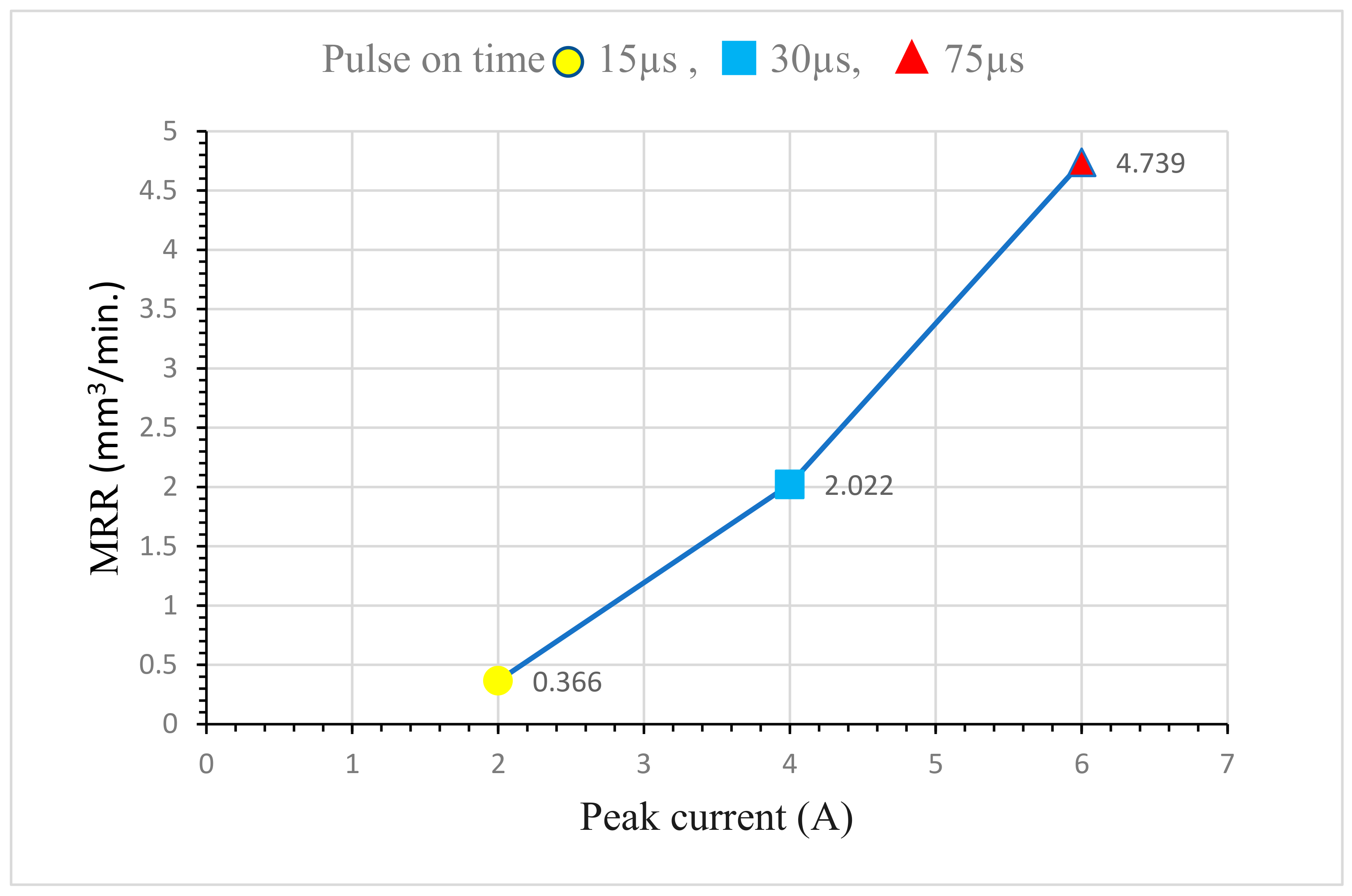
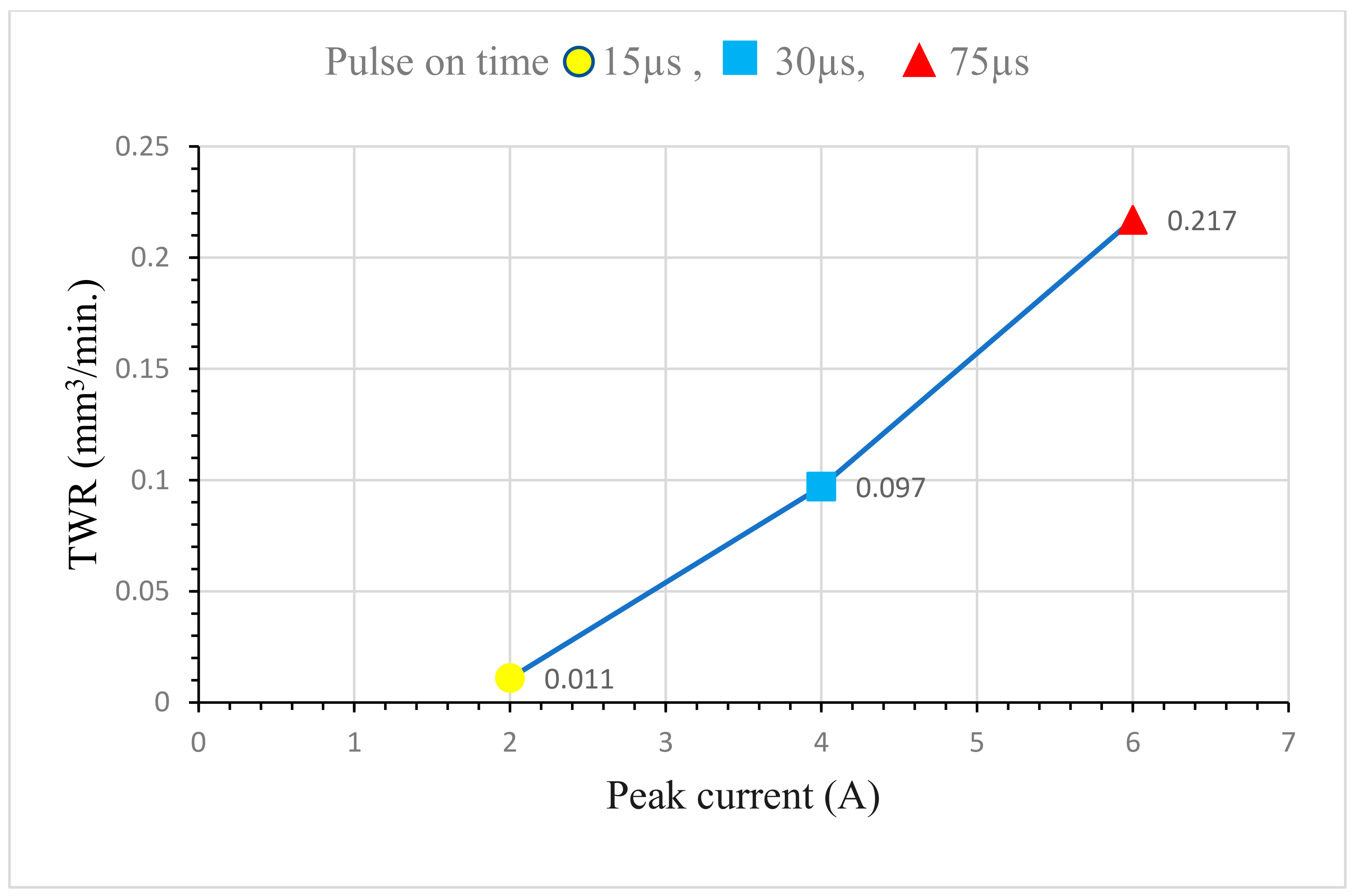
The MRR of tests conducted without powder concentration is displayed in Table 5. As illustrated in Figure 3, MRR was shown to rise in tandem with an increase in peak current. At a peak current of 6 A, the maximum MRR of 4.739 mm3/min was attained. Similarly, as shown in Figure 4, TWR also increased with an increase in the peak current. TWR was lowest at 0.011 mm3/min at a peak current of 2 A.

Table 5.
Output parameters of experiments conducted without powder.
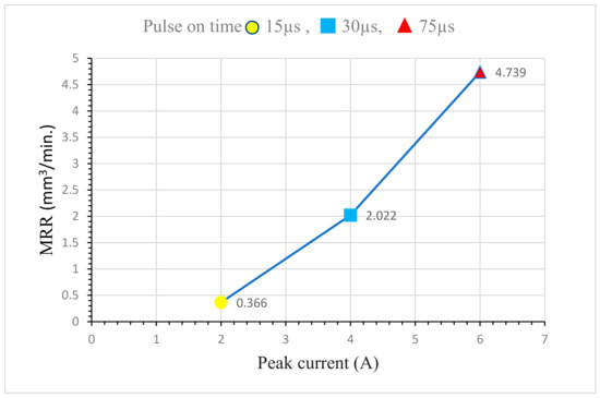
Figure 3.
MRR in EDM without powder.
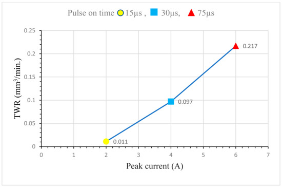
Figure 4.
TWR in EDM without powder.
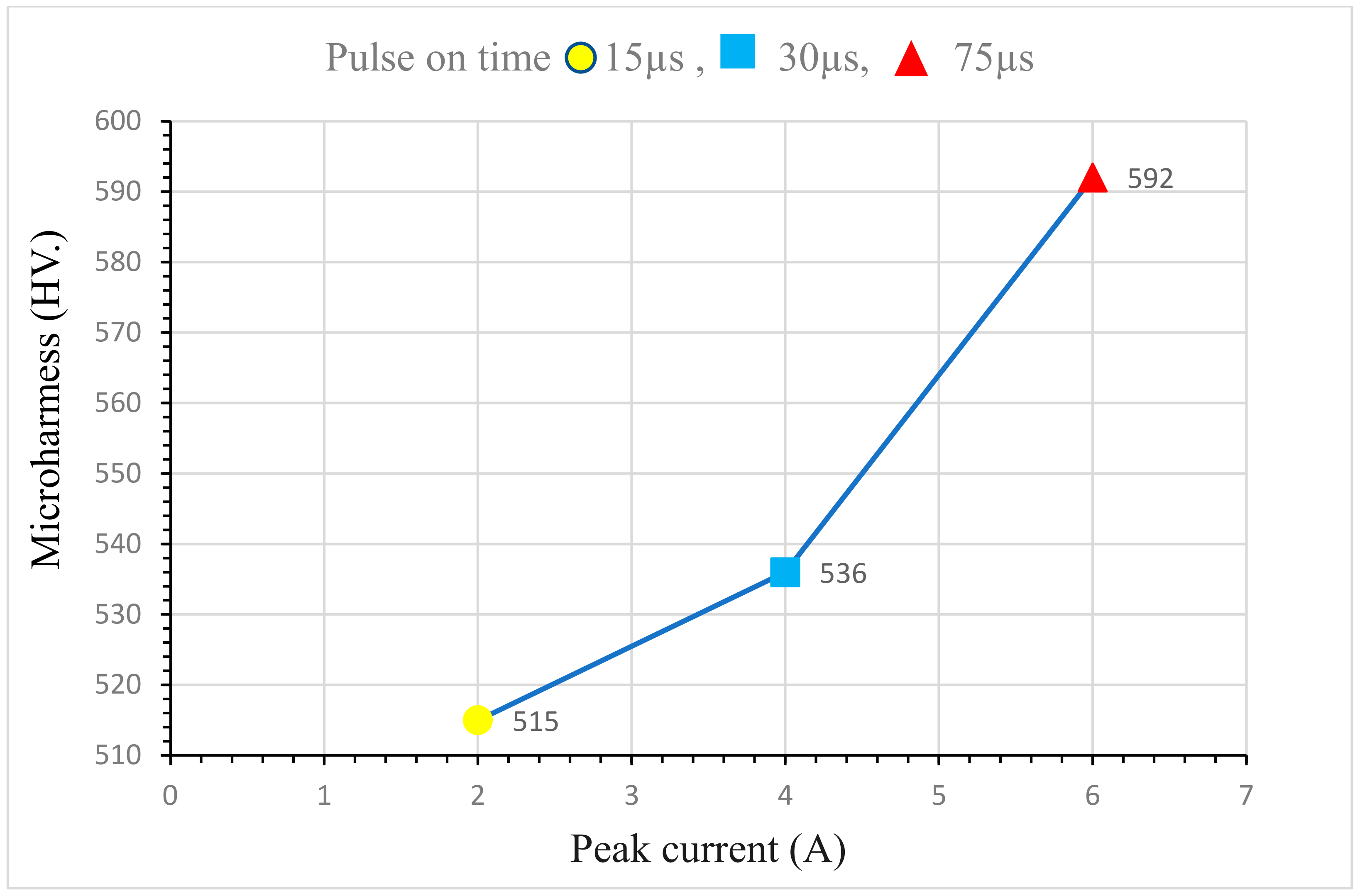
Using the Vickers Microhardness Test, the microhardness of a specimen was determined. A load of 0.025 kgf was applied to the surface of H13 die steel specimens for 10 s using a diamond indenter. As the peak current increased, microhardness also improved (Figure 5). The maximum microhardness achieved without powder was 592 HV at a peak current of 6 A. This increment in microhardness is attributed to the recrystallization of the H13 die steel surface due to the extreme heat and pressure generated by the higher peak current, resulting in a more refined grain structure.
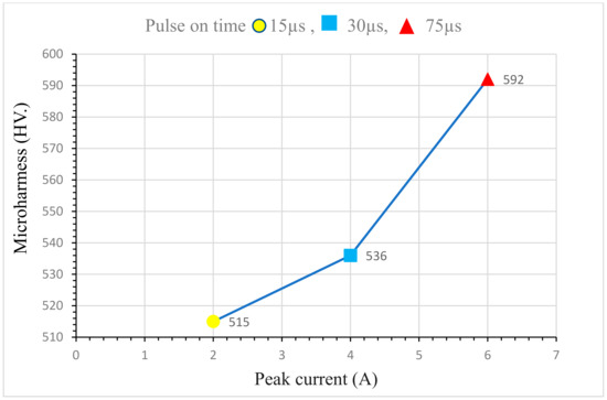
Figure 5.
Microhardness in EDM without powder.
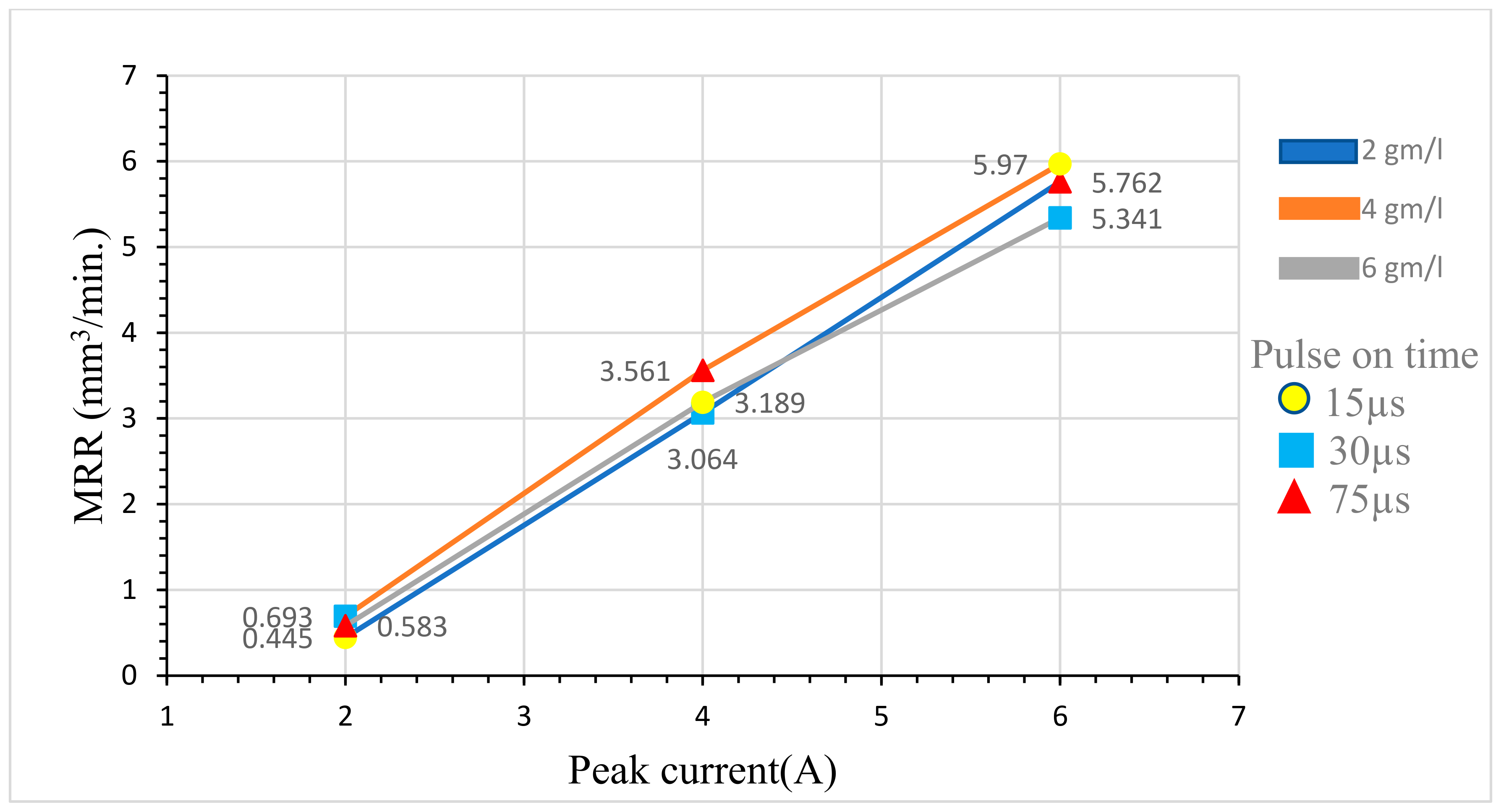
Table 6 displays the findings of the L9 orthogonal array-based EDM experiment using graphite powder. MRR rises from 2 gm/L to 4 gm/L as the powder concentration increases. As illustrated in Figure 6, the MRR is lower at 6 gm/L of powder concentration than at 4 gm/L of powder concentration.

Table 6.
Output parameters of experiments conducted with powder.
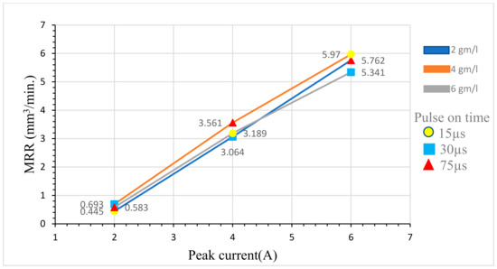
Figure 6.
MRR of powder-mixed EDM with powders of different concentrations.
Moreover, 5.970 mm3/min was the maximum MRR recorded at a peak current of 6 A and powder concentration of 4 gm/L. This is due to the high concentration of graphite powder (6 gm/L) in the machining area, which lowers the dielectric fluid’s ability to effectively insulate the copper electrode and H13 die steel workpiece. Consequently, there are fewer sparks available for material removal, which reduces dielectric performance and leads to a reduced MRR of 5.341 mm3/min.
The MRR of H13 die steel specimens increased when the peak current was increased with constant powder concentration, indicating that MRR is not solely dependent on powder concentration; it largely depends on peak current.
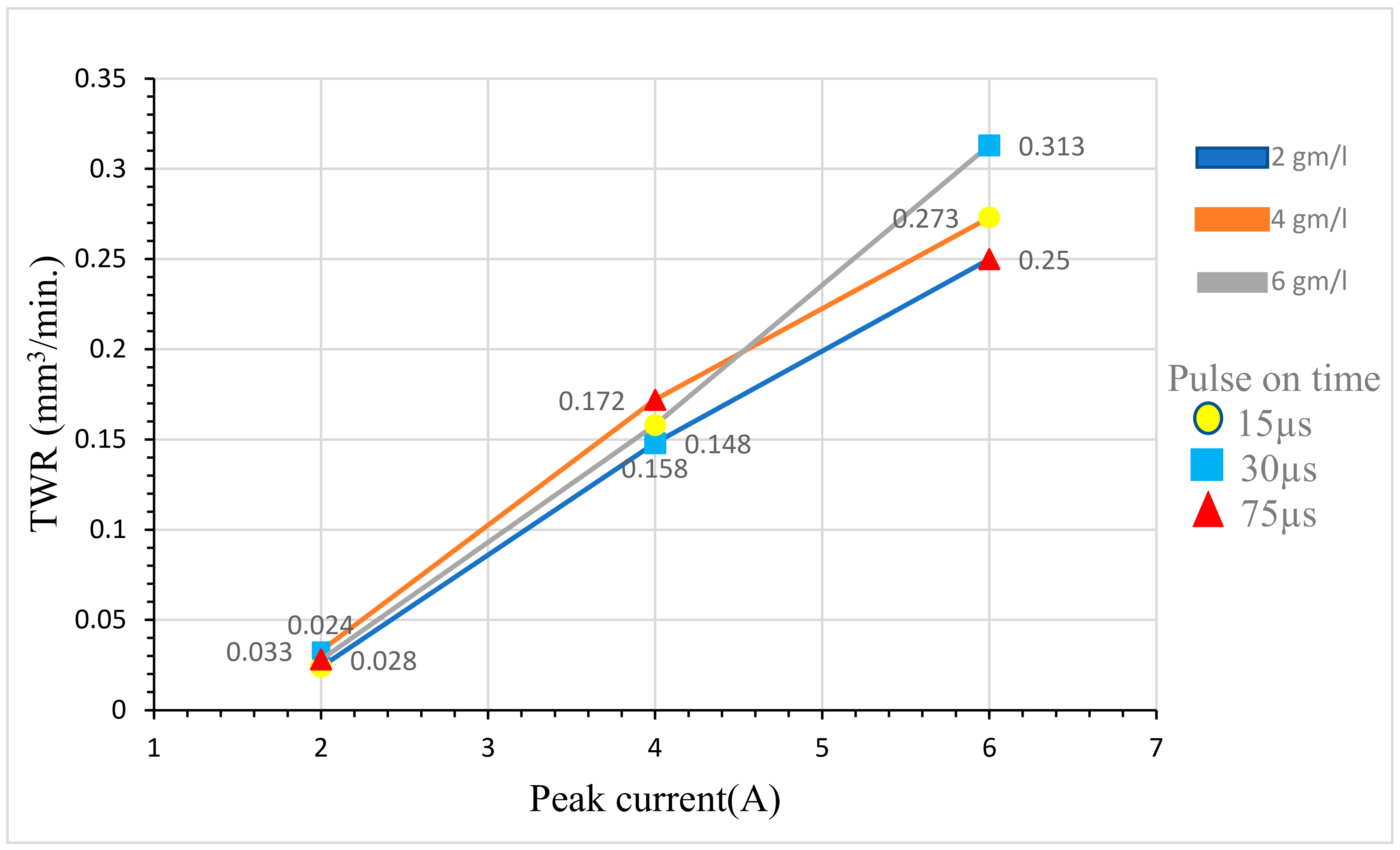
TWR was increased with the increasing powder concentration from 2 gm/L to 6 gm/L with a peak current ranging from 2A to 6A, as shown in Table 7. By comparing the TWR of the copper electrode between the peak current of 2 A and powder concentrations of 2 gm/L with powderless EDM, there is a significant difference, with values ranging from 0.024 to 0.011 mm3/min, as illustrated in Figure 7.

Table 7.
Surface chemical composition of specimen after machining with powder.
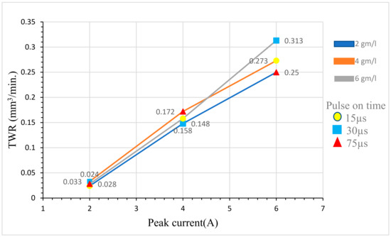
Figure 7.
TWR of powder-mixed EDM with powders of different concentrations.
Using graphite powder as a dielectric fluid during EDM results in an increase in thermal energy density, leading to higher temperatures and energy inputs, which shorten the tool’s life. The powder particles enhance the erosion mechanism by increasing the number of sparks produced and the energy released with each spark, resulting in increased tool wear.
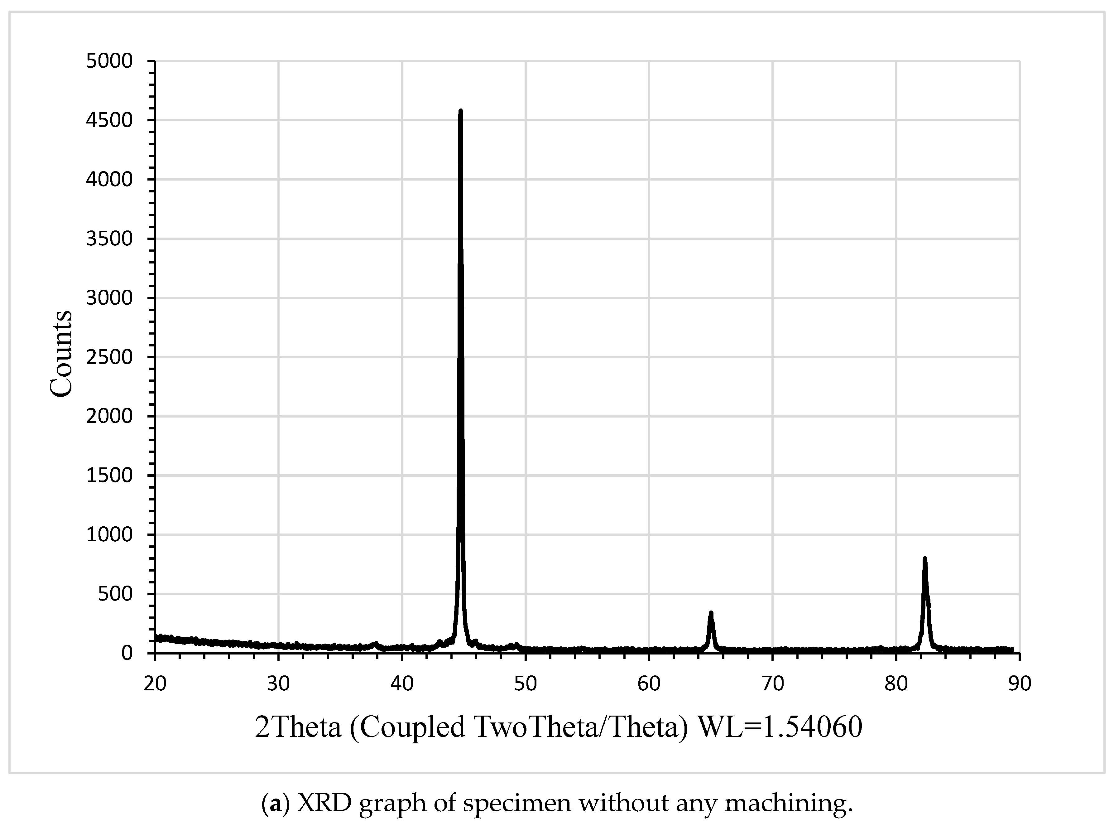
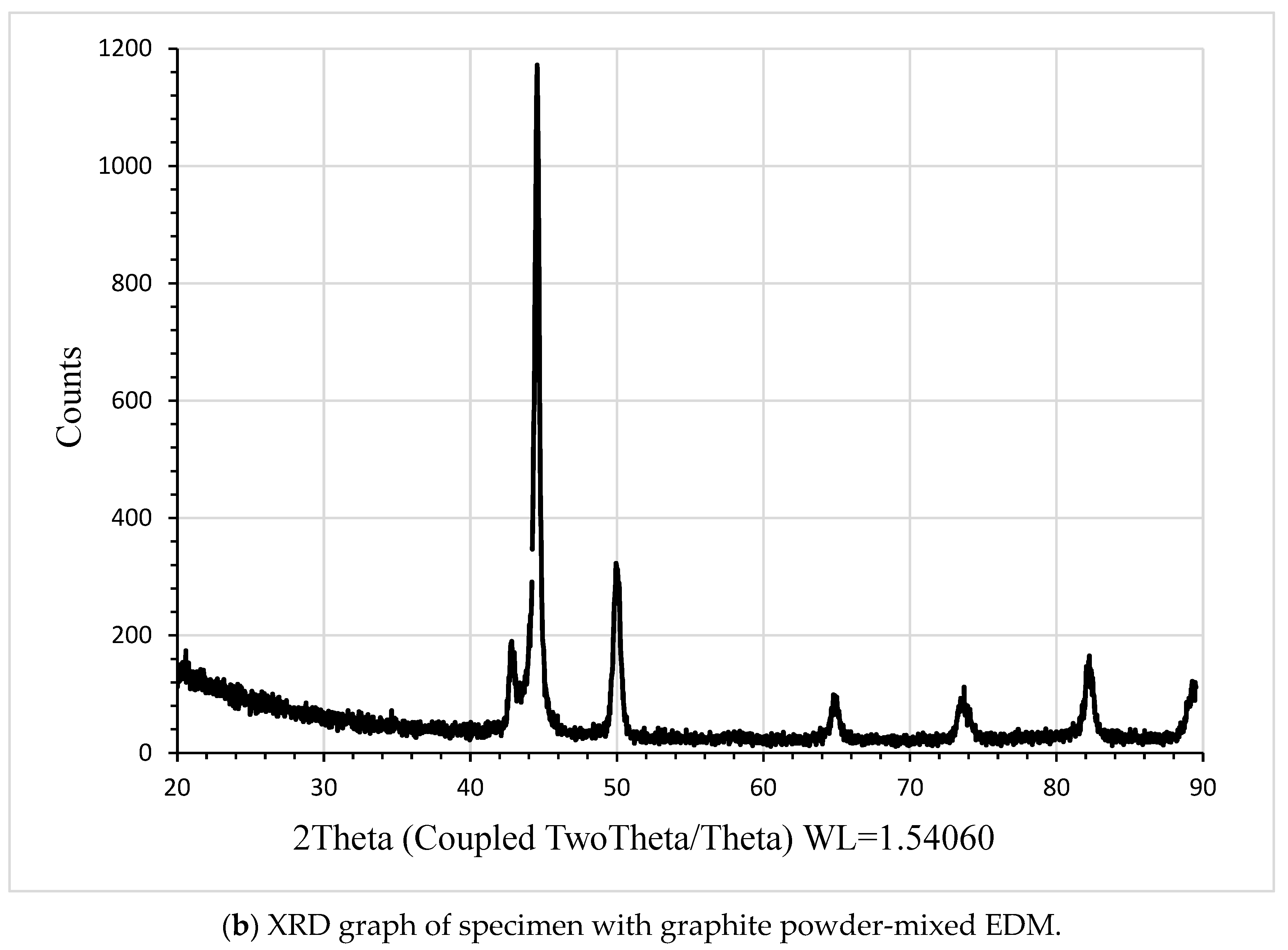
The surface chemical composition of the H13 die steel specimen after powder-mixed machining is determined by EDS and shown in Table 7. According to EDS data, there is a 298% increase in carbon compared to the specimen before machining. Other elements have decreased, including Cr by 8.69%, Mo by 25%, Si by 9%, V by 9%, Mn by 15.7%, Ni by 9%, specimen to confirm the presence of vanadium, iron, manganese, nickel, and chromium and Fe by 3.14%. As seen in Figure 8, X-ray diffraction (XRD) is also performed on the specimen.
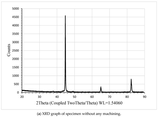
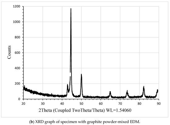
Figure 8.
XRD graph of specimen.
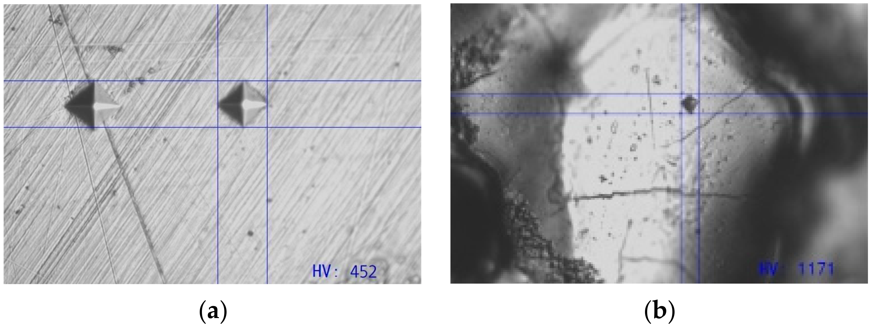
Before any machining operations, the specimen’s microhardness was found to be 452 HV. Figure 9a shows the specimen image at 40× zoom, and Table 6 presents the microhardness of each specimen after it has been machined using graphite powder-mixed EDM at different powder concentrations and peak currents.
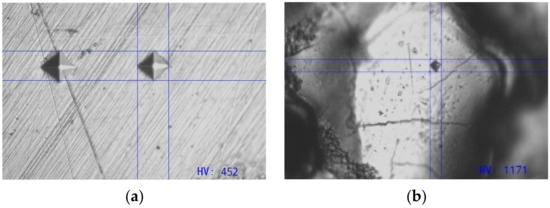
Figure 9.
(a) Hardness test image of specimen before machining. (b) Hardness test image of machined specimen.
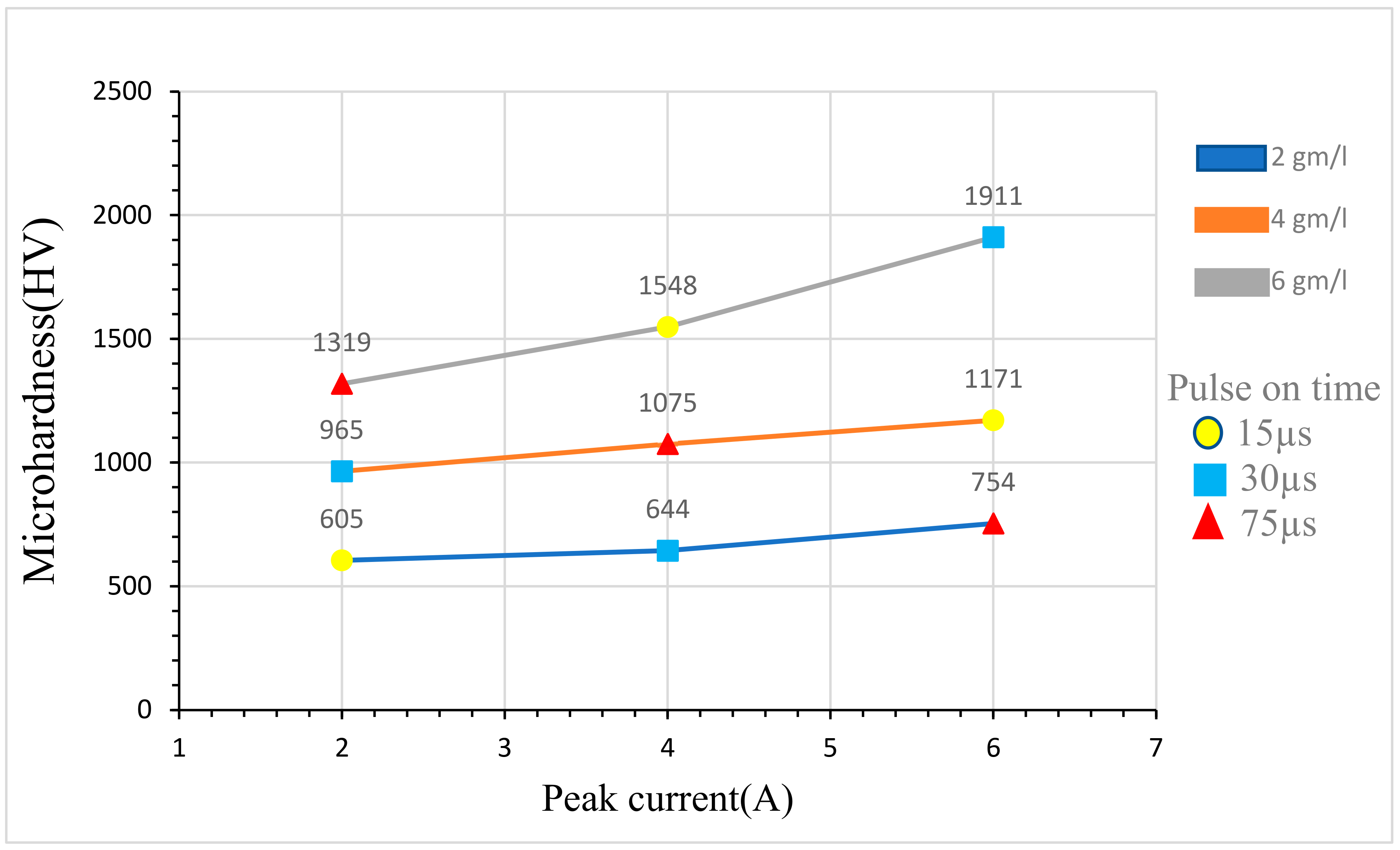
The maximum hardness value achieved is 1911 HV, attained with a powder concentration of 6 gm/L and a peak current of 6 A, as shown in Figure 10. This improvement is ascribed to the graphite powder present in the dielectric fluid, which produces better discharge energy, consistent sparking, and erosion efficiency. The microhardness results of all specimens machined with powder-mixed dielectric fluid indicate that each specimen’s microhardness was increased by adding powder. Table 8 shows how the carbon content of H13 die steel was raised by adding graphite powder to the dielectric fluid, leading to a notable increase in microhardness. However, it is noteworthy that MRR is reduced at a powder concentration of 6 gm/L, which presents a significant disadvantage to achieving the maximum microhardness value at 6 gm/L.
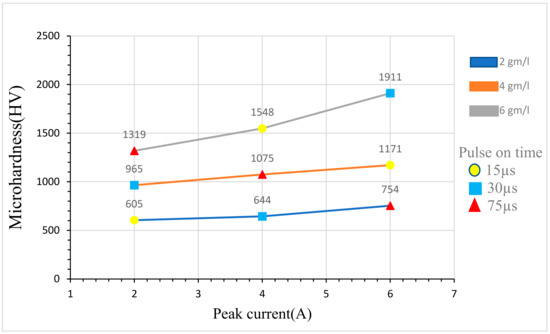
Figure 10.
Microhardness of powder-mixed EDM with powders of different concentrations.

Table 8.
Percentage change in MRR, TWR, and microhardness in experiments conducted with and without powder.
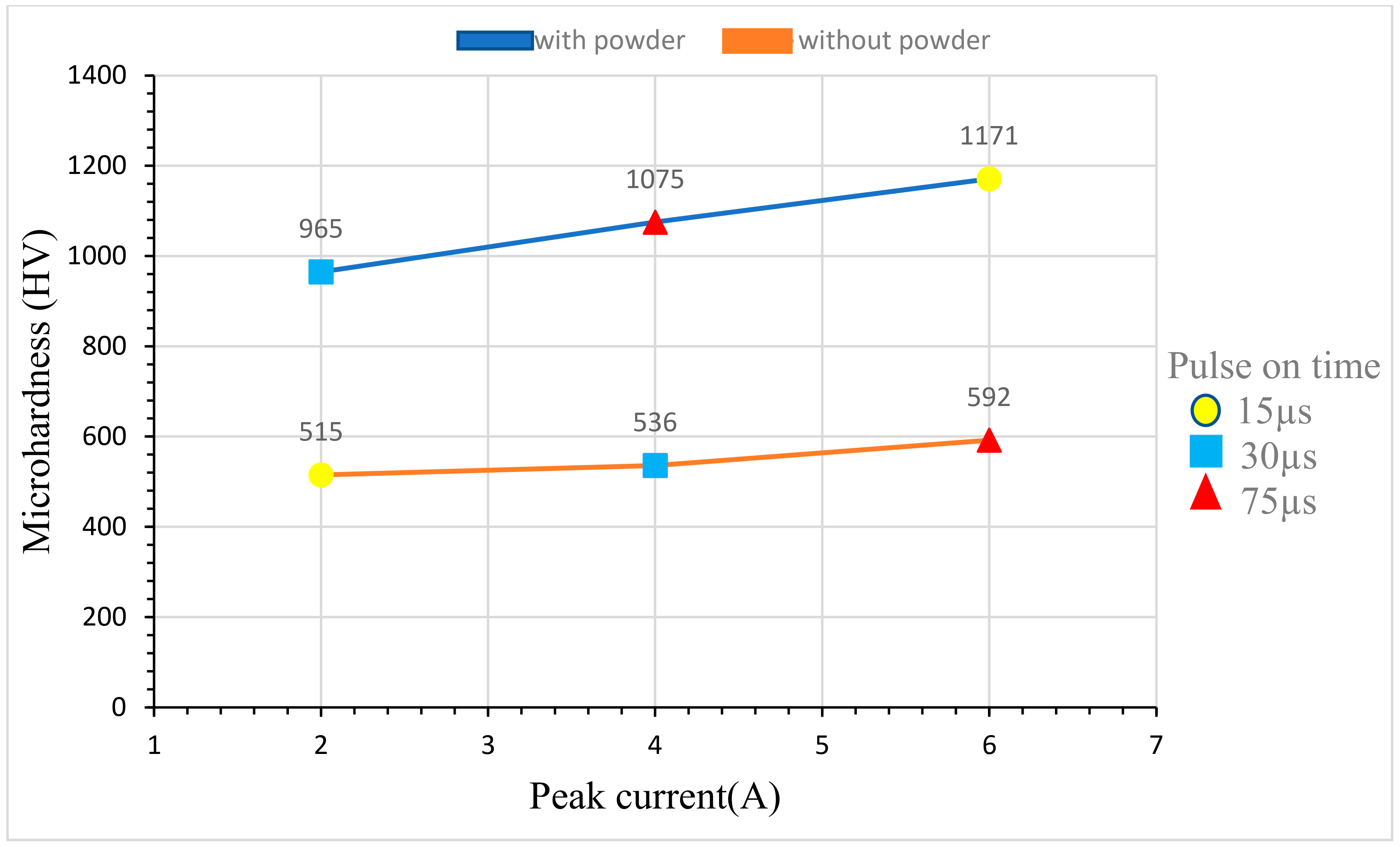
In H13 die steel specimens, a peak current of 6 A and a powder concentration of 4 gm/L produce a microhardness value of 1171 HV without compromising the MRR. Observing the findings of MRR, TWR, and microhardness machined with powder-mixed dielectric fluid, it becomes evident that the optimal powder concentration for an enhanced EDM process is 4 gm/L.
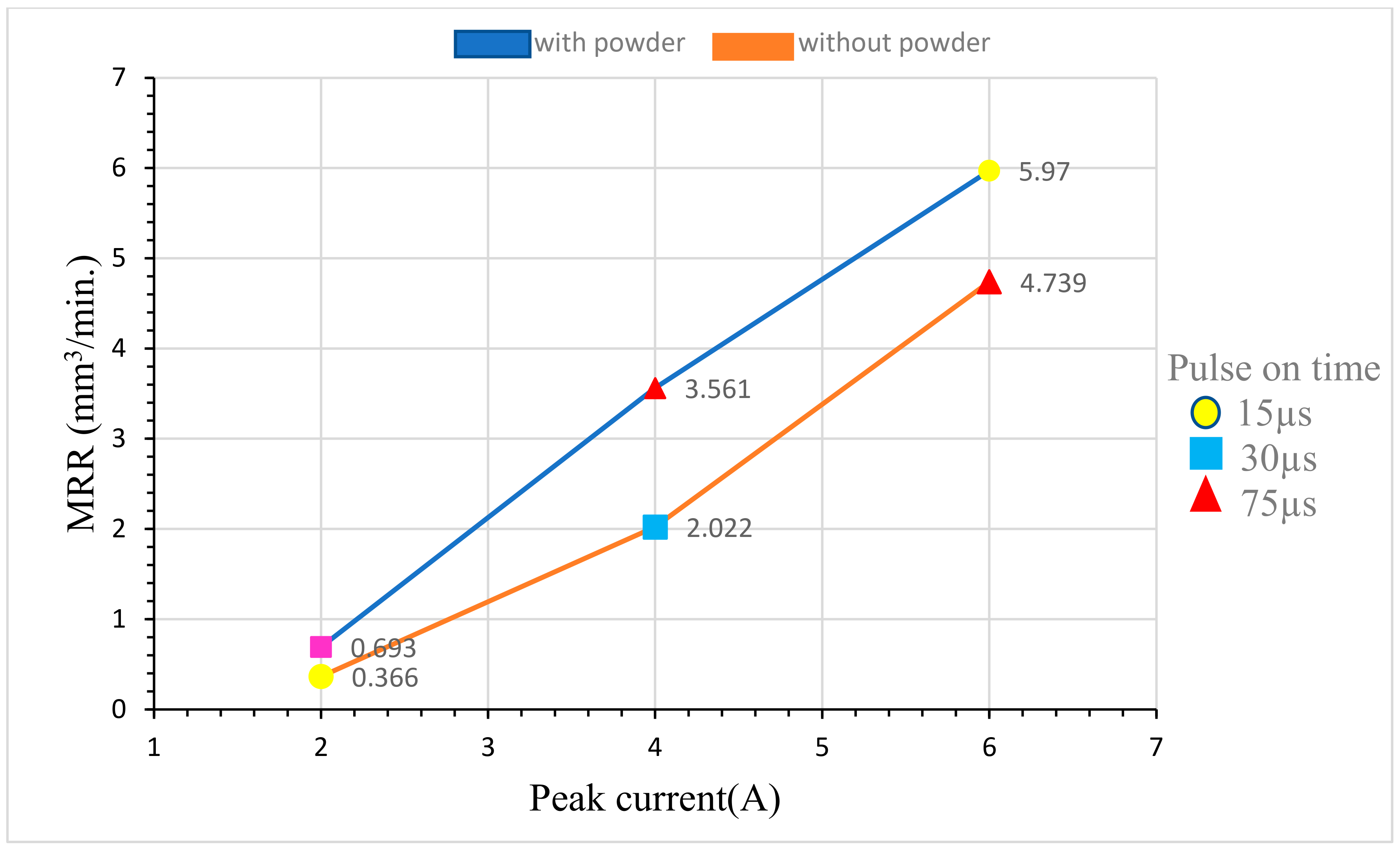
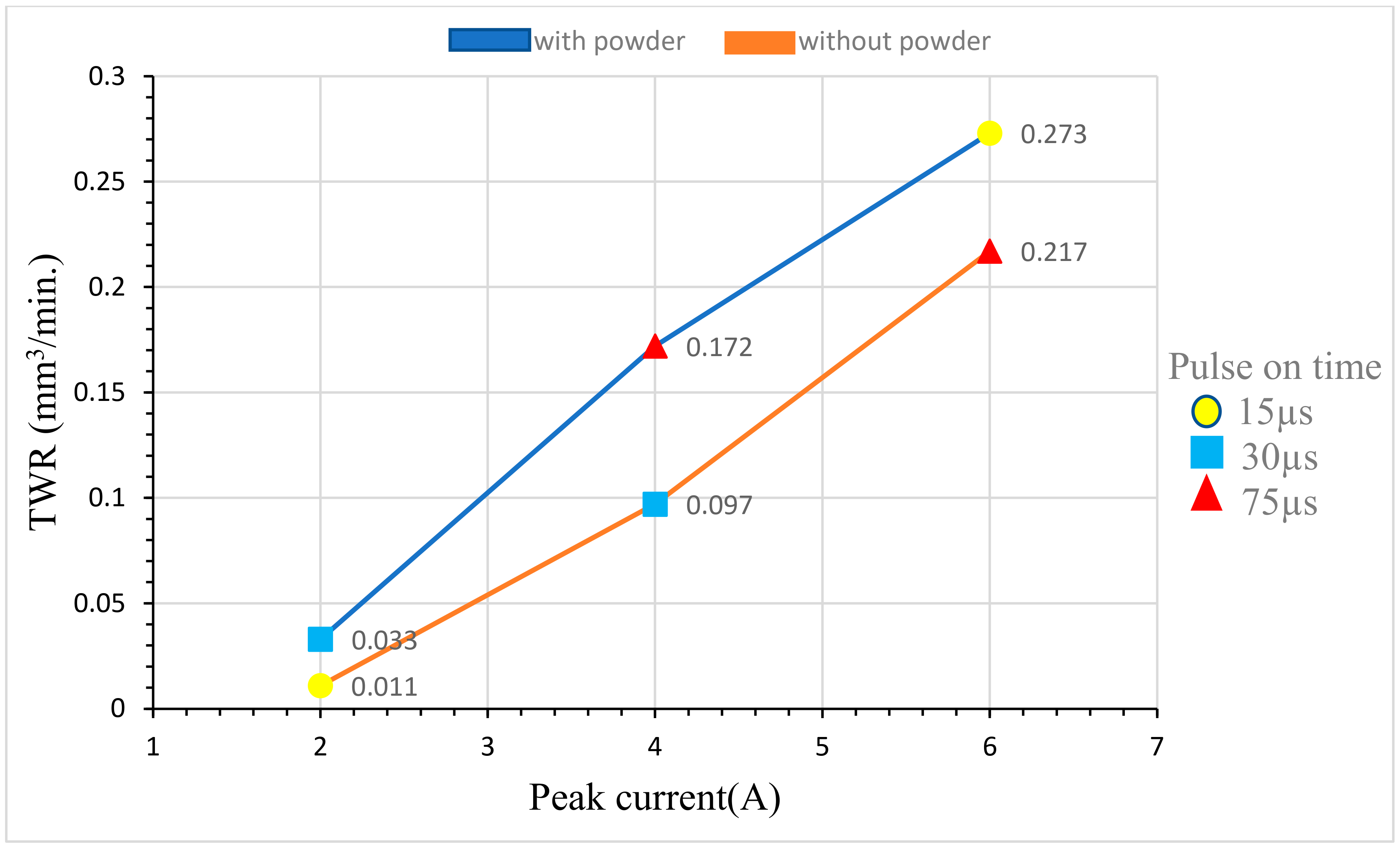
Comparisons of MRR, TWR, and microhardness between powder-mixed and powderless EDM are depicted in Figure 11, Figure 12 and Figure 13, respectively. The MRR of a specimen subjected to powder-mixed EDM has been enhanced by approximately 25.9% compared to the MRR of a specimen without powder-mixed EDM. This improvement is a result of the powder being added to the dielectric fluid. Furthermore, there has been a 118% rise in the TWR of specimens treated with powder-mixed EDM, as detailed in Table 8.
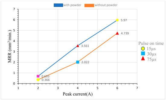
Figure 11.
MRR vs. peak current of experiments conducted with and without powder.
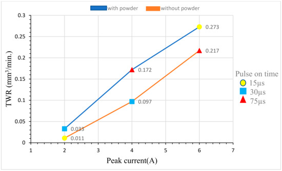
Figure 12.
TWR vs. peak current of experiments conducted with and without powder.
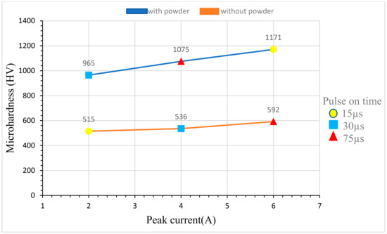
Figure 13.
Microhardness and peak current of experiments conducted with and without powder.
4. Conclusions
The research shows that adding graphite powder to the dielectric fluid during the PMEDM process considerably enhances the surface properties of H13 die steel. The following are the main findings from this study:
- PMEDM improves the machined surface’s microhardness. PMEDM processing increases the microhardness by 159% compared to the unmachined surface. Additionally, PMEDM-based microhardness results are 97.8% better than powderless EDM-based processing. This increase in hardness is attributed to microstructural changes, as evidenced by XRD results, showing the presence of manganese, vanadium, nickel, and chromium silicide. Increased hardness indicates better wear resistance properties of resulting products, making them useful in wear design applications.
- In PMEDM, the highest microhardness is obtained with a peak current of 6 A, a powder concentration of 6 gm/L, and a pulse-on time of 30 µs.
- MRR results of PMEDM-based processing are 25.9% better than the corresponding results of powderless EDM-based processing. The best MRR results are obtained when PMEDM processing is performed with a peak current of 6 A, powder concentration of 4 gm/L, and pulse-on time of 15 µs.
- The TWR of the PMEDM-based processing is 118% higher than the TWR of the powderless EDM process. Furthermore, the minimum TWR for PMEDM is achieved at a peak current of 2 A, powder concentration of 2 gm/L, and pulse-on time of 15 µs.
Author Contributions
Conceptualization, D.S., P.G. and S.S.; methodology, D.S. and P.G.; software, D.S. and P.G.; validation, D.S. and P.G.; formal analysis, D.S., P.G. and S.S.; investigation, P.G.; writing—original draft, D.S. and P.G.; writing—review and editing, D.S., P.G. and S.S. All authors have read and agreed to the published version of the manuscript.
Funding
This research received no external funding.
Data Availability Statement
Data are contained within the article.
Conflicts of Interest
The authors declare no conflicts of interest.
References
- Jeswani, M.L. Effect of the Addition of Graphite Powder to Kerosene Used as the Dielectric Fluid in Electrical Discharge Machining; Elsevier Sequoia S.A: Amsterdam, The Netherlands, 1981. [Google Scholar]
- Wong, Y.S.; Lim, L.C.; Rahuman, I.; Tee, W.M. Near-mirror-finish phenomenon in EDM using powder-mixed dielectric. J. Mater. Process. Technol. 1998, 79, 30–40. [Google Scholar] [CrossRef]
- Yih-Fong, T.; Fu-Chen, C. Investigation into some surface characteristics of electrical discharge machined SKD-11 using powder-suspension dielectric oil. J. Mater. Process. Technol. 2005, 170, 385–391. [Google Scholar] [CrossRef]
- Peças, P.; Henriques, E. Influence of silicon powder-mixed dielectric on conventional electrical discharge machining. Int. J. Mach. Tools Manuf. 2003, 43, 1465–1471. [Google Scholar] [CrossRef]
- Wu, K.L.; Yan, B.H.; Huang, F.Y.; Chen, S.C. Improvement of surface finish on SKD steel using electro-discharge machining with aluminum and surfactant added dielectric. Int. J. Mach. Tools Manuf. 2005, 45, 1195–1201. [Google Scholar] [CrossRef]
- Kansal, H.K.; Singh, S.; Kumar, P. Effect of silicon powder mixed EDM on machining rate of AISI D2 die steel. J. Manuf. Process. 2007, 9, 13–22. [Google Scholar] [CrossRef]
- Kumar, S.; Singh, R.; Singh, T.P.; Sethi, B.L. Surface modification by electrical discharge machining: A review. J. Mater. Process. Technol. 2009, 209, 3675–3687. [Google Scholar] [CrossRef]
- Khan, A.A.; Ndaliman, M.B.; Zain, Z.M.; Jamaludin, M.F.; Patthi, U. Surface modification using electric discharge machining (EDM) with powder addition. Appl. Mech. Mater. 2012, 110–116, 725–733. [Google Scholar] [CrossRef]
- Batish, A.; Bhattacharya, A.; Singla, V.K.; Singh, G. Study of material transfer mechanism in die steels using powder mixed electric discharge machining. Mater. Manuf. Process. 2012, 27, 449–456. [Google Scholar] [CrossRef]
- Kumar, S.; Batra, U. Surface modification of die steel materials by EDM method using tungsten powder-mixed dielectric. J. Manuf. Process. 2012, 14, 35–40. [Google Scholar] [CrossRef]
- Hu, F.Q.; Cao, F.Y.; Song, B.Y.; Hou, P.J.; Zhang, Y.; Chen, K.; Wei, J.Q. Surface properties of SiCp/Al composite by powder-mixed EDM. In Procedia CIRP; Elsevier B.V.: Amsterdam, The Netherlands, 2013; pp. 101–106. [Google Scholar] [CrossRef]
- Marashi, H.; Sarhan, A.A.D.; Hamdi, M. Employing Ti nano-powder dielectric to enhance surface characteristics in electrical discharge machining of AISI D2 steel. Appl. Surf. Sci. 2015, 357, 892–907. [Google Scholar] [CrossRef]
- Joshi, A.Y.; Joshi, A.Y. A systematic review on powder mixed electrical discharge machining. Heliyon 2019, 5, e02963. [Google Scholar] [CrossRef] [PubMed]
- Kumar, S.S.; Varol, T.; Canakci, A.; Kumaran, S.T.; Uthayakumar, M. A review on the performance of the materials by surface modification through EDM. Int. J. Lightweight Mater. Manuf. 2021, 4, 127–144. [Google Scholar] [CrossRef]
- Sharma, G.; Kumar, K.; Satsangi, P.S.; Sharma, N. Surface Modification of Biodegradable Mg-4Zn Alloy Using PMEDM: An Experimental Investigation, Optimization and Corrosion Analysis. IRBM 2022, 43, 456–469. [Google Scholar] [CrossRef]
- Chaudhari, R.; Khanna, S.; Patel, V.K.; Vora, J.; Plaza, S.; de Lacalle, L.N.L. Experimental Investigations of Using Aluminum Oxide (Al2O3) and Nano-Graphene Powder in the Electrical Discharge Machining of Titanium Alloy. Micromachines 2023, 14, 2247. [Google Scholar] [CrossRef] [PubMed]
Disclaimer/Publisher’s Note: The statements, opinions and data contained in all publications are solely those of the individual author(s) and contributor(s) and not of MDPI and/or the editor(s). MDPI and/or the editor(s) disclaim responsibility for any injury to people or property resulting from any ideas, methods, instructions or products referred to in the content. |
© 2024 by the authors. Licensee MDPI, Basel, Switzerland. This article is an open access article distributed under the terms and conditions of the Creative Commons Attribution (CC BY) license (https://creativecommons.org/licenses/by/4.0/).

