Abstract
This article describes the technology for manufacturing a metal composite structure of a metal-cutting tool body. The main problem with using metal 3D-printing is its prohibitively high cost. The initial data for carrying out finite element calculations are presented, in particular, the calculation and justification of the selected loads on the drill body arising from metal-cutting forces. The described methodology for designing a digital model of a metal-cutting tool for the purpose of its further production using SLM 3D metal printing methods facilitates the procurement of a digital model characterized by a reduced weight and volume of material. The described design technology involves the production of a thin-walled outer shell that forms the external technological surfaces necessary for the drill body, as well as internal structural elements formed as a result of topological optimization of the product shape. Much attention in this article is paid to the description of the technology for filling internal cavities with a viscous metal polymer, formed as a result of the topological optimization of the original model. Due to this design approach, it is possible to reduce the volume of 3D metal printing by 32%, which amounts to more than USD 135 in value terms.
1. Introduction
The mechanical engineering industry is striving to find new means and production technologies that can reduce the cost of production. At the same time, new technologies should ensure not only a reduction in production costs, but also the preservation or improvement of the functional parameters of the product, such as strength, the density of the internal structure, surface roughness, dimensional accuracy, hardness, ergonomics, and other parameters [1,2,3]. The labor intensity of manufacturing is of great importance in the cost of manufacturing parts, especially when manufacturing products of complex shapes that have complex internal holes, cavities, and undercuts. In works [4,5,6], methods are given for calculating the labor intensity of manufacturing engineering products, the analysis of which shows that it is often the machine processing time that has the most significant impact on the cost of manufacturing engineering products. Despite the fact that technologists strive to optimize the machining process by using CNC equipment or universal equipment and tools, the ability of production to optimize machine production time is largely limited.
Modern additive manufacturing methods, such as SLM 3D metal printing, can significantly reduce the labor intensity of manufacturing complex-profile parts [6,7,8,9,10,11]. The described technologies make it possible to produce high-strength engineering products from metal powders of various alloys to produce internal cavities and thin walls. The possibility of additive manufacturing of metal products using SLM methods has recently attracted more and more attention from the tool industry. In articles [12,13,14,15,16], researchers propose using 3D-printing for the manufacture of metal-cutting tools, modular cutters and drills, and equipment. In particular, the most relevant area of application for SLM 3D metal printing is the production of prefabricated metal-cutting tool housings (Figure 1), since the presence of cutting heads made of hard alloys or high-speed steel in such a tool allows for highly efficient processing. The housing itself serves for the correct positioning of the cutting plates or heads; for the location of the technological cavities necessary in it, such as cooling channels; and for transmitting torque from the machine spindle to the cutting head.
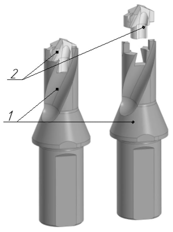
Figure 1.
Case drill model TID250F20-1.5. 1—drill body, 2—cutting head.
Among the advantages of manufacturing metal-cutting tool bodies, researchers highlight the following: no need for complex production preparation when changing the nomenclature; the ability to grow curved spatial surfaces, such as cooling channels; low positioning error due to the manufacture of the part in one installation; and high productivity (15 cm3 per hour). At the same time, 3D metal printing also has a number of disadvantages for the purposes of using this technology when printing metal-cutting tool bodies. The disadvantages include the low dimensional accuracy of the resulting products, corresponding to accuracy grade 14 or +/−50 microns, as well as high roughness, corresponding to Ra10 +/−2, which requires the inclusion of finishing operations of working surfaces using subtractive production methods in the technological process of manufacturing the product. But the main disadvantage of using metal 3D-printing is the excessively high, non-competitive production cost. Depending on the region and the availability of equipment and technology, the cost may vary, but, for example, in the Eastern European region, the cost of 3D metal printing using SLM technology varies from USD 7 to USD 15 per 1 cm3, depending on the brand of powder.
The market retail price of the TID250F20-1.5 drill body is about USD 400, which makes the production of the tool body using additive technology generally unfeasible; in addition, the printed body will also require additional finishing of the working surfaces using subtractive production methods.
At the same time, the relevance of searching for new, quickly mastered technologies for enterprises remains an important and pressing task. If the task of processing the outer surfaces of a body tool using CNC machines is solvable, then mastering technologies for making internal, curved, spatial technological cavities remain an urgent task. For example, electrical discharge machining technologies require, in addition to an electrical discharge machine, the production of an electrode tool. Also, when piercing spiral holes, it is necessary to combine the translational and rotational motion of the workpiece and the electrode tool [17,18,19,20,21,22]. These and other technological limitations force many enterprises to abandon the development of complex production technologies and limit themselves to the production of simpler designs. Modern production places high demands on the tool industry; there is often a request for the manufacture of special metal-cutting tools for a specific workpiece or technological process, which can be characterized by a low weight, high cooling efficiency, and complex outer surface profile, and could be manufactured in a short time. Therefore, the development of additive technologies for 3D-printing with metals is an attractive area for various machine-building enterprises, which makes it possible to increase the competitiveness of their products while reducing the cost of 3D-printing.
Thus, there is an important and urgent task of developing a way to reduce the cost of metal 3D-printing, which can give a wider range of engineering enterprises the opportunity to use metal 3D-printing in their technological processes.
The purpose of this article is to provide a method for reducing the volume of 3D-printing a cabinet tool and, as a result, reducing the cost of its production. This article provides a methodology for designing a solid model of a drill body for its subsequent production using metal 3D-printing methods. The proposed technology is a new, patented method and has not previously been found in the scientific literature. At the same time, the newly designed drill has a smaller volume of metal while providing the necessary strength. This can significantly reduce the cost of 3D-printing such a drill bit. It is proposed to achieve a reduction in the volume of metal material through the use of topological shape optimization. This makes it possible to obtain internal load-bearing structural elements that provide the necessary strength of the drill body. After obtaining the power structural elements, through a Boolean operation, these elements are combined with models of external working surfaces. In this way, an optimized model of the drill body is obtained, in which the necessary structural strength is ensured and the working surfaces of the tool are preserved, but also, internal cavities are formed after removing the residual material. Since, in topological optimization, it is proposed to take into account only the loads from the cutting force in order to obtain a maximum reduction in the volume of material, the forces from the technological equipment are not taken into account. Therefore, the interiors of any structures must also be reinforced to ensure the strength of new structures when loaded from technological equipment. The article describes the technology of reinforcing the internal cavities of a drill body of a new design with a durable metal polymer. This is necessary to ensure the strength of the drill body when exposed to loads from technological equipment that were not taken into account when solving the topological optimization problem. The original design of a vibro-vacuum unit for reinforcing hollow forms with a metal polymer is also described.
2. Materials and Methods
To describe the proposed method for manufacturing composite structures of metal-cutting tools, the concept of a metal composite product has to be introduced. A metal composite product (a special case is the composite body of a metal-cutting tool) is a metal shell of a thin-walled body that has complex profile internal elements, such as cooling channels or structural elements for rigidity, and is filled with a durable metal polymer composition.
Metal-polymer materials include a wide range of different cold-hardening thermosets, presented in Table 1. In general, metal polymers are a compound consisting of a modified polymer matrix (20%), which is 80% filled with various fine fillers (steel, ceramics). The filler, metal or ceramic, imparts unique properties to the cured material, and the polymer matrix ensures the uniform distribution of particles in the compound.

Table 1.
Types of metal polymers by functional purpose.
Metal polymers are dispersion-filled repair composite materials of the cold-welding system. This class of materials is designed to eliminate various problems that arise during the operation of equipment in industrial enterprises. Metal polymers are made on the basis of epoxy resins and powder fillers modified by physical and chemical methods. High adhesive properties combined with structural strength, corrosion resistance, and wear resistance make it possible to use metal polymers when restoring machine parts, as well as as adhesives, sealants, protective coatings, and when replacing surfacing welding. After curing, they can be machined, just like metals. The unique properties of metal polymers include the following: the ability to restore parts from any materials (ferrous and non-ferrous metals, non-metals); gluing dissimilar materials, including metals and non-metals; high chemical resistance to acids, alkalis, petroleum products, solvents, and other aggressive environments; the absence of temperature and installation stresses after hardening; and the ability to restore defects without disassembling and dismantling components and mechanisms.
Table 2 shows the physical, mechanical, and thermophysical properties of polymer composite materials and structural materials on the market. Structural materials include various alloys and steels.
Table 2.
Comparison of physical, mechanical, and thermophysical properties of polymer composite materials and structural materials.
An analysis of Table 2 and studies [28,29,30,31,32] shows that the strength characteristics of polymer composite materials are inferior to structural ones, and their anisotropy is also observed. For example, the tensile strength under compression is 5 times more than the tensile strength under tension, and the tensile strength with normal separation is 10 times less than the tensile strength under tension. The thermal properties of structural materials differ 30 times from the properties of polymer composites. The most important parameter of polymer composite materials is a lower level of heat resistance.
Based on the experience of using polymer composite materials for their use as a material for the formative parts of a mold [33], it can be concluded that for the need to reinforce hollow, thin-walled shell forms grown by SLM 3D metal printing, it is most rational to use the LEO Ferro-Hrom metal polymer [34], the characteristics of which are given in Table 3.
Table 3.
Physico-mechanical and technological characteristics of the LEO Ferro-Hrom metal polymer.
To study the strength of the drill body, the finite element method has been used [36,37,38]. For the topological optimization of the digital solid model, in order to develop curved cooling channels and create an internal structural frame and internal cavities, the Altair Inspire 2022.1.1 software was used, as well as Kompas3D V20.0.0.3002. Topological optimization methods are described in [39,40,41,42]. Topological optimization allows us to perform a strength calculation of a digital model in order to identify those areas of the model material through which payloads are transferred from the fastening points to the actuating surfaces. For example, for a cabinet drill, this is the transfer of loads from the place where the shank is secured in the machine chuck to the surfaces of the seating planes of the drill head. Based on the results of calculations, the material in the body of the digital model that is not involved in the transfer of payloads is removed. This technique allows us to reduce the material consumption of the model, taking into account a given safety margin.
To carry out strength calculations and topological optimization, it is necessary to know the initial load data. To understand the cutting forces that a drill experiences during drilling, a diagram of the cutting forces for a drill body is presented in Figure 2.
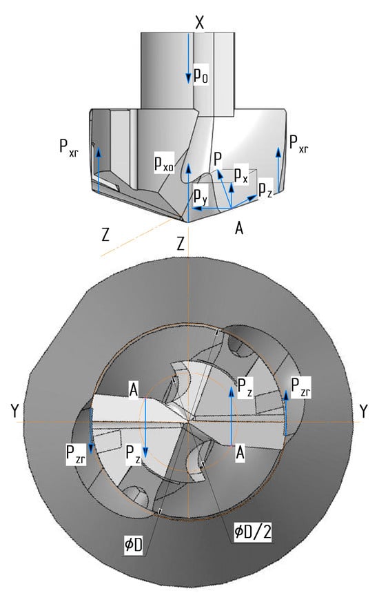
Figure 2.
Diagram of cutting forces acting on a drill body.
According to [43,44], the cutting force is laid out as shown in Figure 2 for several components of forces, such as Px (the force parallel to the axis of the drill or axial force); Py (the force perpendicular to the drill axis or radial force); and Pz (a tangential force), the vector of which is tangent to the circle on which point A is located, that is, the point of the resultant force. The presented diagram of forces is equal for both drill blades.
On the bridge, only the cutting forces represented by the axial forces (Pxo) are determined; the other two forces are negligibly small.
The auxiliary edge (ribbon) perceives force Pzr, the vector of which is directed tangentially to the circle of nominal diameter (D), as well as force Pxr, the vector of which is directed parallel to the axis of the drill. Early research suggests that the nature of these forces represents frictional forces.
Using simple mathematical transformations, the total force acting along the axis of the drill along the X axis (1) can be presented.
The research [45,46] shows that the total cutting torque during drilling is spent on the main cutting edges in the amount of 0.8 fractions of the total value on the main cutting edges, as well as 0.08 on the transverse edges; 0.12 of the total force is spent on friction from chips on the drill and strips drills on the surface of the workpiece.
The research shows that the power (W) spent on cutting is the sum of the power spent on rotating the drill and the power spent on the feed movement. Since the feed power is in the range from 0.5 to 1.5% of the rotation power, it can be neglected in the calculations. According to [47], the power spent on drill rotation can be calculated using Formula (2).
where Mkr is the torque during drilling processing, Nm; n is spindle rotation speed, rpm.
A significant reduction in feed force and torque occurs when using lubricating and cooling technological means, and can reach up to 40%. But when calculating strength, options with the most loaded cases of drill operation should be used in order to guarantee performance under the most difficult conditions [48].
Also, axial force and torque depend on the characteristics of the material being processed, the material of the cutting insert, the cutting conditions, and the tool geometry. Tool geometry is one of the main factors when calculating the cutting force when drilling. The cutting process is influenced by such tool geometry parameters as the cutter angle, the inclination angle of the cutting edge, the radius of curvature of the tip of the cutting edge, and the angle between the feed direction and the direction perpendicular to the workpiece surface. All of these parameters are taken into account while calculating coefficients when determining the cutting force. Usually, cutting forces are determined using standard tables and reference books or using special calculators The reference materials specify the cutting force values, taking into account correction factors, particularly the observational parameters of all cutting parameters and the geometric tool.
Thus, the power expended can be known, which can be determined experimentally by removing it from the CNC machine rack. By calculating it using special calculators, the data for loading the drill in programs, using the FEM module (finite element analysis module) to calculate the strength of the elements of the drill body, are obtained. It facilitates the design of a new drill body in the future, taking into account new approaches to its manufacture.
When referencing technological data [43,44,45,46,47,48], it has been established that when drilling holes with a diameter of 20 mm with a feed value of S0 = 0.1 mm/rev in a steel workpiece, the tabulated value of the axial cutting force is equal to Ptabl = 3600 N. The axial cutting force of the line depends on the machinability coefficient of the material, which for steel with a hardness HB = 170–229 is equal to Kp = 1.0. Thus, the axial cutting force is P0 = 3600 N, while the cutting force on the main sharp edges is P = P0*0.8 = 2880 N. Considering that, within the frame drill model, there are 2 limits that perceive the cutting force from the main edge, the cutting force on one edge is equal to 1440 N. The calculated value of the cutting force on the main cutting edge, equal to 1440 N, was used when loading the model and performing strength calculations using the finite element method.
An analogue of 40X steel was chosen as the body material of the model subjected to research.
3. Results
The essence of the proposed technology for manufacturing metal composite structures, proposed as a way to reduce the cost of the additive manufacturing of metal products, such as a drill body, is to reduce the volume of 3D-printing. It is proposed to reduce the volume of metal 3D-printing through the topological optimization of the product shape. However, when solving the problem of topological optimization, when specifying fastening locations, the program makes such surfaces conditionally rigid and unchangeable. With this formulation of the problem, we do not always take into account the additional loads on the product. On the other hand, calculating a product using the finite element method and carrying out topological optimization on its basis, taking into account all possible loading scenarios, on products whose shape has many spatial curves and small dimensions, can overload the calculation model. Overloading the calculation model may require a large number of calculation resources. A complex calculation model can lead to calculation errors and the formation of various collisions. The results of the calculation can be represented not only by the creation of solid load-bearing structures, but also by the formation of various surface elements, etc. The optimized model itself can be overloaded with additional structural elements, various internal trusses and supports, and excessive thickening of structural elements. In this case, additional strength elements of the structure can neutralize the usefulness of using topological optimization, which can be reflected in the increased material consumption of the structure and negate the economic efficiency of 3D metal printing. Further, this article reveals those surfaces that are not involved in the direct transmission of cutting forces, but are important from the point of view of the performance of the drill body.
3.1. Description of Important Technological Surfaces of the Drill Body
The main internal surface of the body frame is the surface of the cooling channels (Figure 3).
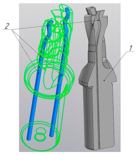
Figure 3.
Internal cooling channels of a drill body with spatial curvature: 1—drill body model; 2—profile of cooling channels.
Making internal cooling channels using subtractive processing methods is a rather complex technological task, requiring special equipment and the development of complex technologies. Typically, cooling channels are made either along a broken path, by crossing cylindrical holes, or by making a straight hole in the body blank, followed by heating and twisting the turns of the drill. That is, the turns of the drill are formed by heating and twisting the milled workpiece. Another technology is the use of electrical discharge machining. Electroerosion requires significant technological preparation, the manufacture of electrode tools, and the combination of translational and rotational motion. At the same time, the most important and difficult-to-achieve factor when using subtractive technologies is the manufacture of holes for cooling channels with a non-round profile and variable cross-section. Changing the cross-sectional profile can increase the coolant flow, which leads to a decrease in the thermal stress of the cutting process and an increase in tool life [49,50,51]. Figure 4 shows a comparison between the cross-sectional area of a circular cooling hole (a) and the complex cross-sectional shape (b).
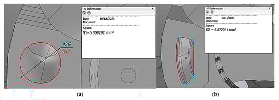
Figure 4.
Scheme for calculating the cross-sectional area of cooling channels of various shapes. (a) Round section: S = 5.309 mm2. (b) Optimized profile: S = 6.8 mm2.
From the automated calculations shown in Figure 4, it is clear that the area of the optimized shape of the cooling channel is increased relative to the circular one by 1.56 mm2 or by 29.38% relative to the circular section with a diameter of 2.6 mm.
An increase in the cross-sectional area of the cooling channel can help to increase the volume of coolant that flows to the cutting zone. This can help to effectively cool the work tool, preventing it from overheating and improving the overall performance. Another positive factor is the more efficient removal of chips and metal particles from the cutting zone. A larger cross-sectional area can reduce coolant pressure, which can be helpful in preventing unnecessary stress on the tool and can result in a longer tool life.
The next critical surface of the drill body, subjected to associated loads, is the surface of the chip flutes (Figure 5).
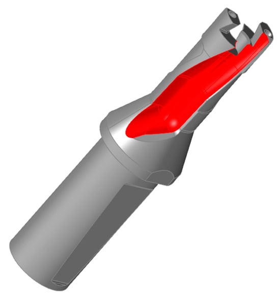
Figure 5.
The outer surface of the chip flute of a drill body.
This surface absorbs the forces generated by the friction of the chips on this surface. In addition, during the cutting process, the formation of a chip packing effect in the channel formed by the surface of the hole being machined and the chip removal groove is possible. Due to the properties of the material being processed, incorrect processing modes, and high roughness of the chip flute, chips may accumulate, become compacted, and be collected in a bag. Then, the formed package, if not removed, begins to exert pressure on the surface of the chip groove. Although the described forces are insignificant compared to the cutting forces, when manufacturing the drill body in the form of a thin-walled shell, they can lead to the deformation of the drill body and its failure. Therefore, it is necessary to provide reinforcement to the inner surface of the chip flutes. For this purpose, it is proposed to use filling voids with a metal-polymer composition.
The correct design of the tool shank area also requires a careful analysis of Figure 6. The loads that the drill body shank absorbs when it is clamped in the chuck significantly influence the topological optimization process. The compression forces of the shank from three-jaw, collet, hydroplastic, and other types of chucks are significant, since it is thanks to these forces that torque is transmitted from the machine spindle to the drill body. Consequently, cavities formed during topological optimization cannot be left hollow, as this leads to the deformation of the structure from accompanying loads that are not taken into account in the optimization problem and are perceived by the structure of the drill body. When designing a shank as a thin-wall structure, it is important to provide a bridge from the opposing surfaces of the shank that are subject to clamping forces. In this case, the clamping forces on opposite sides compensate themselves. This can be achieved by filling the voids with a metal polymer that has sufficient compressive strength [32,34].
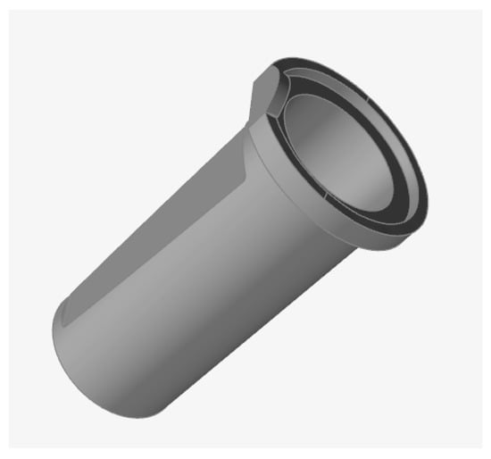
Figure 6.
Thin-walled area of the drill body shank.
Another group of surfaces that have special requirements are surfaces for mounting the cutting head (Figure 7).
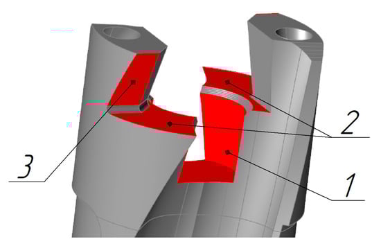
Figure 7.
The surface of the drill body mating with the cutting head. 1—surface of the centering hole; 2—supporting surface of the cutting head; 3—thrust surface of the cutting head.
Section 2 (Materials and methods) provides the necessary data for the topological optimization of the drill body shape. The material and loads arising from metal cutting are indicated. In Section 3.1., the working surfaces of the drill body are described; all of these surfaces have an important technological purpose to ensure the functionality of the drilling process and must form a thin-walled shell when creating a topologically optimized design; that is, they must be preserved. Next, this article reveals the description of the methodology for creating the shell structure of a drill body using topological shape optimization tools.
3.2. Methodology for Topological Optimization of the Drill Body
When solving a topological optimization problem, the first step is to make sure that the original model subjected to the optimization procedure is able to withstand workloads and has the necessary safety margin [39,40,41,42]. The margin of safety of the original model indicates that there is the ability for optimization in the model. If the strength of the original model is not ensured or the model has a safety factor equal to one, this means that such a model cannot be optimized. The safety factor of the original model is calculated using a standard FEM analysis, which is described in detail in earlier studies [36,38]. The process of calculating the strength of the TID250F20-1.5 drill body model is deliberately not given in this article to reduce its volume. It should be noted that the minimum design safety factor for the drill body of the TID250F20-1.5 model corresponds to 1.2. In addition, this model is widely used in industry and its initial strength has been confirmed in practice.
In the second step of the topological optimization method, it is necessary to modify the original model by identifying unchangeable areas in it. Unchangeable areas include those surfaces that are of significant technological importance, that is, those surfaces that have been described in Section 3.1. At this stage, some difficulties arise.
To select immutable areas using standard tools, AltairInspire provides the “partition” tool (Figure 8).
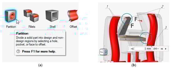
Figure 8.
Procedure for specifying an immutable region: (a) “partition” tool icon in the AltairInspire toolbar menu; (b) creation of two unchangeable areas with a thickness of 1 mm: 1—unchangeable areas, 2—zones where the unchangeable areas go beyond the contours of the original model, 3—window for setting the thickness of the unchangeable area.
As can be seen from Figure 8, when using the “partition” tool, the generated unchangeable areas when selecting working faces are generated in the form of prismatic objects, and do not take into account the contours of the original model itself. Therefore, zones 2 (Figure 8) are formed where unchangeable areas go beyond the contours of the original model. Since these unchangeable areas are subsequently isolated in the form of separate solid elements that can make up the final optimized model, the original geometry of the tool is violated. When selecting many faces that form the contour of the original model, collisions often arise, which leads to not the formation of a solid element, but to the formation of a surface or situation where it is completely impossible to create a new object.
There are also other limitations when creating immutable regions, such as the need for finishing, since the quality of 3D-printing does not meet the requirements for the roughness of some surfaces (Ra 0.8) and dimensional accuracy corresponding to the six–seven accuracy level. Therefore, it should be taken into account that some places in the model should not only merely form a thin-walled shell, but also ensure the subsequent fastening of this part in the machine, for example, in the centers. That is, the thickness of the metal part in these places must ensure that the centering holes are made in these places, and the internal structure must provide strength in the direction of the efforts to secure the workpiece on the machine.
The next question is what should be the minimum thickness of those unchangeable surfaces that are necessary in the design of the drill, but do not experience significant loads. It is advisable to make such surfaces as thin as possible, taking into account the fact that they can subsequently be reinforced with a metal polymer from the inside. But, here, some technological limitations appear. The first technological limitation is what minimum wall thickness a 3D printer can provide. Since the printed workpiece is elongated, if the outer walls are too thin and the thickness of the internal elements varies, internal stresses, ironing, and deformations may occur. In addition, an important factor for the performance of the drill body is the hardness of its outer surfaces, which can subsequently be ensured by chemical–thermal treatment or thermal treatment. From reference [52], it is recommended to use a minimum wall thickness of 2 mm.
During the iterative modeling of immutable regions, after many failures, it is most advisable to avoid selecting immutable regions in elements such as the head of the drill body; due to its small size and many faces and surfaces, this process is very labor-intensive and does not provide effective material savings as a result of topological optimization. Therefore, it is recommended to select a complex area by simply cutting a plane at the transition point of this area to a simpler part of the model. In principle, when designing a thin-walled shell of a drill body, it is recommended to completely divide the model into separate parts and process these parts separately. For example, in the case of a drill body, it is recommended to distinguish three parts, the mounting head (Figure 9a), the middle screw part (Figure 9b), and the shank (Figure 6).
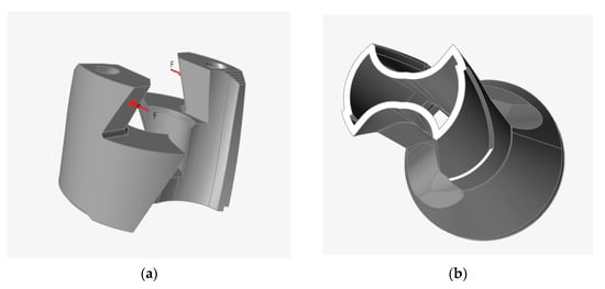
Figure 9.
Selecting unchangeable areas of the drill body model in AltairInspire; (a) selection of the landing head; (b) highlighting the thin-walled shell of the middle screw part of the drill body.
If it is not practical and difficult to process the seating head of the drill body (Figure 9a) in order to obtain a shell from it, then obtaining a thin-walled shell for the screw middle part of the drill body (Figure 9b) is not difficult.
At the final stage, it is necessary to design the unchangeable areas occupied by the cooling channels. This task is trivial and does not pose any difficulty for the designer. This is carried out by specifying a trajectory line, along which a sketch of the cross-sectional contour of the cooling channel is drawn out. Tools for modeling cooling channels are present in any modern CAD program; for example, in this study, the tools of the Kompas3D V20.0.0.3002 software product were used.
Thus, four parts of the model were obtained; these are the landing head (Figure 9a), the thin-walled middle screw part (Figure 9b), the thin-walled shank (Figure 6), and the cooling channel rods. By connecting these parts together using a Boolean operation and subtracting the resulting region from the original drill model, the region of the topology optimization space (Figure 10) was obtained.
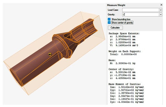
Figure 10.
The area where the drill body changes is subject to the topology optimization procedure.
Next, the hollow body and optimization zone are assembled, the necessary fastenings are specified and work loads are applied, the material characteristics are specified, and the procedure for calculating the topologically optimized shape is carried out. As a result of modeling and calculations, new models of drill bodies with round and profile cooling channels are obtained, characterized by the presence of internal technological cavities. In Figure 11, the assembly of the components of the drill body is shown with profile cooling channels. The assembly consists of a head, surfaces of cooling channels, a load-bearing structural element obtained through topological optimization, and the thin-walled shell of the housing and a shank.
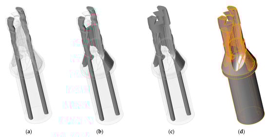
Figure 11.
Assembling the components of the drill body: (a) is a structural part of the cooling channels; (b) is a structural part of the optimized zone and cooling channels; (c) is a structural part of the drill body, consisting of an optimized zone, cooling channels, and landing head; (d) is the assembly of all elements of the optimized drill body model.
By combining all of the resulting parts into a single model, it is possible to obtain an optimized model of the drill body, for which it is necessary to calculate the strength using the finite element method. Figure 12 shows the safety factor diagram of the new optimized drill body design. Figure 12 also shows the symbols of the imposed restrictions on the movement of the model, which are necessary for calculations by the finite element method. The surfaces on which restrictions on the degrees of freedom are imposed are the cylindrical surface of the drill shank (restriction 1) (Figure 12), installed in the chuck and through which torque is transmitted from the spindle. There is also restriction 2 (Figure 12), imposed on the end surface of the conical section of the drill body, which serves as a limiter for the extension of the drill relative to the axis of the chuck hole. These restrictions are conventionally depicted by red cones. An analysis of the diagram shows that the minimum safety margin corresponds to the value of 1.2, which means that the created design provides the necessary safety margin for the drill body.
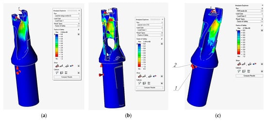
Figure 12.
Safety factor diagram of a drill model. (a) A diagram of the safety factor of the solid drill body (min 1.3); (b) a safety factor diagram of the optimized drill body, but without the middle outer part (min 0.5); (c) a safety factor diagram of the optimized drill body (min 1.2); 1 is a symbol of the cylindrical part of the shank, deprived of the ability to move under loads; 2 is a symbol of the end of the conical part of the body, deprived of the ability to move under loads.
Despite the fact that the safety margin of the drill is provided by the metal structure of the drill body, it is necessary to take into account that the internal cavities formed as a result of the optimization of the internal part of the drill can be reinforced with a metal-polymer composition. The reinforcement of the internal cavities with a metal polymer increases the strength and rigidity of the structure. However, the acquired strength provided by the metal-polymer material is not taken into account in this stage of topological optimization. This is due to the complexity of constructing a computational model, which requires gluing together a large number of faces of the metal polymer and metal parts of the computational model.
In Figure 13, the mass-centering characteristics of the original, solid model of the drill body are shown, and Figure 14 shows the resulting optimized model of the drill body.
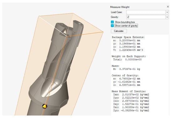
Figure 13.
Mass-centering characteristics of the original model of a core drill.
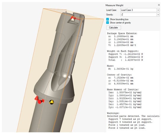
Figure 14.
Mass-centering characteristics of a topologically optimized model of a core drill.
As can be seen from the calculation of the mass-centering characteristics, the weight of the drill body model is reduced from 337.3 g to 134 g, which, with a density of 8000 kg/m3 of the metal powder intended for use for the 3D-printing of the EP648 brand (XH55B5MБTУ), can correspondingly be equal to a volume of 42.16 cm3 and 16.75 cm3.
The difference in the design of the metal part of the drill body is reflected in the change in the coordinates of the center of gravity of the drill, which is shown in Figure 13 and Figure 14. However, in the future, when filling (reinforcing) the voids of the body with a liquid metal polymer, the coordinates of the center of gravity will change, since new material will be added to the structure. When constructing internal structural elements using topological optimization methods, a plane of symmetry is specified in order to eliminate the imbalance of the model relative to the longitudinal axis. However, SLM 3D metal printing cannot ensure the absolute symmetry of the manufactured model due to various production factors. Therefore, the finishing treatment of the composite drill body must include the operation of balancing the finished tool in order to prevent the center of gravity from moving from the axis of the tool and to eliminate vibrations during its operation.
3.3. Filling Internal Cavities with Metal Polymer
The proposed technology for obtaining a metal composite structure of a drill body, by filling the internal cavities formed as a result of the topological optimization described in the previous section, is not the simplest task. This is due to the rheological characteristics of the metal polymer. The metal polymer itself has a viscous consistency and requires special equipment to implement the technological process of filling hollow forms. Also, the shell form itself requires minor modifications.
To implement a method for filling a hollow shell mold with a viscous metal polymer, a vibration-vacuum method for filling hollow shell molds with viscous metal polymers has been developed [53]. Regarding the modification of the drill body model, it is necessary to provide the model holes through which the metal polymer can be fed into the hollow body. These holes must be located in the lower part, at the end of the shank. And in the upper part, it is necessary to provide exit holes.
The essence of the vibration-vacuum method is illustrated in Figure 15, which shows a digital model of the developed device.
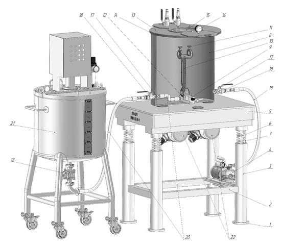
Figure 15.
Digital model of a vibro-vacuum device for implementing a method of filling shell molds with a viscous metal polymer.
Previously, using one of the known 3D-printing methods, a thin-walled shell mold (10) of the product is manufactured with projections (11) and the sprue (12) provided in it. The mold (10) is fixed in a clamp (9) inside the vacuum chamber (8) and, using a line (20), its sprue (12) is hermetically connected to the fitting (17), externally, using the line (20) and taps (18) connected to the container (21), which contains a liquid metal-polymer composition. The container (21) can be either a simple volume vessel or one of the known devices for mixing and dosing two-component compounds, such as metal polymers. The vacuum chamber (8) is closed from above with a lid (13).
The vacuum pump (4) is turned on, which, through a vacuum line (19) connected to a valve (18), which in turn is connected through a fitting (17) to the vacuum chamber (8), pumps out air from the vacuum chamber (8), creating a vacuum in it of up to 400 Pa (to the level of boiling of the metal polymer). In this case, the cover (13), due to the seal (14), is tightly pressed against the open end of the vacuum chamber (8). The vacuum level is monitored by visually monitoring the readings of the vacuum gauge (16). Upon reaching the specified vacuum level in the vacuum chamber (8), valve (18) connects the vacuum chamber (8) with the vacuum line (19) closed and the vacuum pump (4) switched off.
The vibrators (22) are turned on, as a result of which the base plate (5), under the influence of vibration excitation from the vibrators (22), as well as gravity on the one hand and the energy of the springs (7) on the other, begins to vibrate, making translational movements relative to the frame (1), being centered by the rods (6) coaxially relative to the racks (3). The vibrating base plate (5), due to its rigid connection with the vacuum chamber (8), transmits vibration to it, and it, in turn, to the clamp (9) fixed on its bottom, which in turn transmits vibration to the form (10) installed in it.
During the vibration of the mold (10), the valve (18) installed on the container (21) with the liquid metal polymer and the valve (18) installed on the fitting (17) of vacuum chamber (8), connected to each other by a line (20), open. The liquid metal polymer from the container (21), under the influence of a vacuum formed in the vacuum chamber (8) and, accordingly, in the mold (10), is sucked into the mold (10), filling it, while, due to the presence of vibration in the mold, the liquid metal polymer has greater fluidity, which makes it possible to fill all cavities and undercuts of the mold (10) formed, including both the geometric design of the product itself and the technological features of the layer-by-layer manufacturing of the mold (10) using 3D-printing methods. Monitoring the filling of the mold (10) with the liquid metal polymer is carried out by visually monitoring the filling of the vents (11) of the mold (10) with the liquid metal polymer, carried out through the viewing window (15) in the lid (13).
After the appearance of the liquid metal polymer in the vents (11), by closing the valves (18) on the vacuum chamber (8) and the container (21), through which the liquid metal polymer is supplied, the supply of the liquid metal polymer to the mold is stopped, and the vibrators (22) are turned off. The line (20) connecting the container (21) with the vacuum chamber (8) is disconnected from the tap (18).
Next, the container (21) can be connected to the next device, with another mold (10), to repeat the cycle of filling the mold (10) with the liquid metal polymer, or it can be cleaned of liquid metal polymer residues chemically.
After curing the metal polymer in the mold (10), by opening the valve (18) connecting the vacuum chamber (8) with the vacuum line (19), atmospheric pressure is established in the vacuum chamber (8), and the cover 13 is removed. The internal line (20) connecting the fitting (17) to the sprue (12) is removed and chemically cleaned before the next use. A composite product consisting of a shell mold (10) and a metal polymer filling is removed from the clamp (9). Next, the sprue (12) and protrusions (11) are removed mechanically. In this way, a composite product is obtained, consisting of a thin-walled shell and a metal polymer filler.
The fitting (17) and the tap (18) through which the metal polymer is supplied are cleaned chemically (for example, using a special solvent) of the metal polymer residues in them, after which the device can be reused. Figure 16 shows a laboratory installation for filling thin-walled shell molds with a liquid metal polymer.
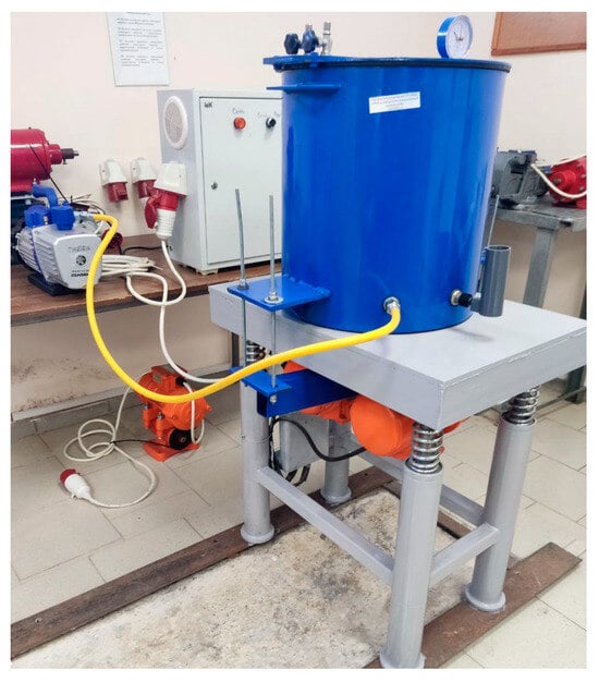
Figure 16.
Laboratory vibration-vacuum installation for implementing a method for manufacturing metal-composite products.
The installation presented in Figure 16 was used for the manufacture of metal-composite mold-forming plates. Figure 17a shows a composite mold plate manufactured in the installation, consisting of a metal frame (1) and a metal polymer mold (2). In Figure 17b, the composite mold (4) is shown, which is mounted on an injection molding machine. The mold consists of a matrix and a punch (4) with metal polymer forming parts (2) made in them. Figure 17b also shows part 3 (gear) cast from polypropylene in a composite mold.
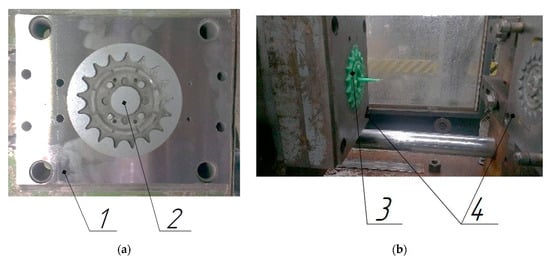
Figure 17.
Composite metal metal-polymer-forming equipment, manufactured using a laboratory installation (Figure 16): (a)—view of the parting plane of the forming part; (b)—view of the mold installed on the injection molding machine; 1 is a metal clip; 2 is a metal-polymer-forming part; 3 is a product cast in a mold (gear); 4 is a composite mold mounted on an injection molding machine.
4. Conclusions
This article describes a methodology for designing a thin-walled shell shape of a drill body using topological optimization methods. Based on the design results, it is possible to obtain a drill body model within the necessary safety margin and that, at the same time, can be characterized by a reduced volume of material. Table 4 shows the calculation of the cost of manufacturing a drill body using 3D-metal-printing methods for a solid model and an optimized one with internal technological cavities.
Table 4.
Calculation of the cost of 3D-printing with metal drill body TID250F20-1.5 using the SLM method in various designs.
Table 4 shows that the estimated cost of manufacturing a drill body using metal 3D-printing methods decreased by 32.26%, which makes the use of metal 3D-printing for the purpose of manufacturing a drill body as an economically feasible solution. In this case, simply manufacturing a drill body, even optimized by topological optimization methods, with a reduced volume of material is also not applicable, since the formed cavities must be filled with something in order to give the required rigidity to the entire structure.
The drill body does not experience significant thermal stress during the cutting process, since effective cooling of the cutting zone is ensured, and the cutting zone itself is removed from the body due to the presence of a cutting head. Consequently, temperature expansions are negligibly small and do not affect the performance of the metal-composite structure.
Many manufacturers use molten metal to fill internal processing cavities. By using different materials in the design of body tools, manufacturers achieve the dampening of the tool’s own vibrations, which has a beneficial effect on the quality of the machined surface when working with such a tool. The influence of the metal–metal-polymer bond in the composite structure of the drill body from the point of view of vibration damping has not been studied to date, but is of significant research interest.
At the same time, the proposed vibration-vacuum method of filling voids with a metal polymer and the equipment for its implementation are much simpler and cheaper compared to the equipment used for filling cavities with molten metals. The vibro-vacuum filling of voids is safer; the work does not require special training and can be carried out by a specialist without high qualifications.
The technological holes provided at the end of the shank (Figure 18a) and in the head part (Figure 18b), through which the supply of the liquid metal polymer into the cavity of the thin-walled shell mold is ensured, are also necessary for removing non-sintered powder from the internal cavity of the drill body after 3D-printing.
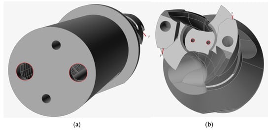
Figure 18.
Technological holes in the drill body: (a) technological holes in the end of the shank; (b) technological holes in the head part.
Thus, using the example of optimizing the model of a drill body and the use of technology for manufacturing a metal-composite structure, by filling the internal cavities with a metal polymer, an economic justification was given for the feasibility of using metal 3D-printing technology in the manufacture of a body tool.
The described technology cannot be limited only to the manufacture of case metal-cutting tools and can undoubtedly be used for the manufacture of other engineering products. The scope of application of the described technology can only be limited by the imagination of the design engineer.
Thanks to the proposed technology, it is possible to reduce the cost of 3D-printing a drill body by USD 135.89, while the safety margin of the optimized model, although decreased from the original model by 0.1, remained within the specified parameter of 1.2.
Author Contributions
N.S.L.: Conceptualization and methodology; M.C.: data curation and writing—original draft preparation; B.S.C.: visualization and investigation; M.D.G.: software and validation; A.A.P.: supervision; A.M.: resources; A.A.T.: writing—reviewing and editing; A.C.: software. All authors have read and agreed to the published version of the manuscript.
Funding
This study was supported by the Russian Science Foundation (grant no. 23-79-10022, https://rscf.ru/project/23-79-10022/, accessed on 1 February 2024).
Data Availability Statement
The data presented in this study are available upon request from the corresponding author. The data are not publicly available as they are also part of ongoing research.
Acknowledgments
The authors are grateful to the team of the High Technology Center (HTC) of BSTU, as well as V.G. Shukhov for assistance in providing design capacities.
Conflicts of Interest
The authors declare no conflicts of interest.
References
- Shan, Z.; Song, W.; Fan, C.; Wang, J. Development Strategy for Precision Manufacturing of Composite Components Facing 2035. Chin. J. Eng. Sci. 2023, 25, 113. [Google Scholar] [CrossRef]
- Bagherzadeh, A.; Budak, E.; Ozlu, E.; Koc, B. Machining behavior of Inconel 718 in hybrid additive and subtractive manufacturing. CIRP J. Manuf. Sci. Technol. 2023, 46, 178–190. [Google Scholar] [CrossRef]
- Mishra, H.; Madan, A.; Abhimanyu. Impact of industry 4.0 on flexible manufacturing system in precision manufacturing. Int. Res. J. Mod. Eng. Technol. Sci. 2023, 5, 4667–4673. [Google Scholar]
- Lubimyi, N.; Voronenko, V.P.; Polshin, A.; Gerasimov, M.; Sergey, A.; Öztürk, O.K.; Chetverikov, B.; Tikhonov, A.; Ryazantsev, V.; Mikhailovich, S.V.; et al. What is the economic feasibility of manufacturing a metal-metal- polymer composite part compared to other technologies? Aust. J. Mech. Eng. 2022, 20, 1–12. [Google Scholar] [CrossRef]
- Tlija, M.; Al-Tamimi, A.A. Combined manufacturing and cost complexity scores-based process selection for hybrid manufacturing. Proc. Inst. Mech. Eng. Part B J. Eng. Manuf. 2022, 237, 1473–1484. [Google Scholar] [CrossRef]
- Kim, K.; Park, K.; Jeon, H.W. The Impact of Design Complexity on Additive Manufacturing Performance. In IFIP International Conference on Advances in Production Management Systems; Springer Nature: Cham, Switzerland, 2022. [Google Scholar] [CrossRef]
- Khan, A.; Singh, A.K.; Dugala, N.S. Leverage of Metal 3D Printing Technology in the Automotive Industry. In International Conference on Production and Industrial Engineering; Springer Nature: Singapore, 2023. [Google Scholar] [CrossRef]
- Jhinkwan, A.; Kalsi, S.; Pankaj, P. An overview on 3D metal printing technology in automobile industry. AIP Conf. Proc. 2023, 2558, 020028. [Google Scholar] [CrossRef]
- Iftekar, S.F.; Sukindar, N.A.; Amir, A.; Azami, M.; Aabid, A. Enhancing metal 3d printing with fused deposition modeling—A short review. Int. J. Res. Anal. Rev. (IJRAR) 2023, 2, 424–428. [Google Scholar]
- Horvath, J.; Cameron, R. Metal 3D Printing and Casting; Apress: Berkeley, CA, USA, 2020. [Google Scholar] [CrossRef]
- Gadagi, B.; Lekurwale, R. A review on advances in 3D metal printing. Mater. Today Proc. 2020, 45, 277–283. [Google Scholar] [CrossRef]
- Pizhenkov, E.N.; Podgorbunskikh, V.M.; Roshchin, V.A. The use of SLM 3D printing technology in the manufacture of hob and modular cutter parts. In Proceedings of the International Scientific and Practical Conference “Modern Conditions of Interaction between Science and Technology”, Perm, Russia, 11 November 2018; Volume 2, pp. 91–97. [Google Scholar]
- Popok, N.N.; Portyanko, S.A. Preparing the production of block-modular cutters using 3d prototyping. Bull. Vitebsk. State Technol. Univ. 2021, 40, 94–106. [Google Scholar] [CrossRef]
- Pizhenkov, E.N.; Berezin, I.M. Method of basing replaceable carbide inserts in the housings of prefabricated cutting tools. Fundam. Res. 2017, 8, 302–307. [Google Scholar]
- Pizhenkov, E.N.; Podgorbunskikh, V.M.; Roshchin, V.A. Manufacturing of prefabricated drilling head housings using SLM 3D printing technology. In Proceedings of the International Scientific and Practical Conference “Breakthrough Scientific Research as the Engine of Science”, Magnitogorsk, Russia, 4 December 2018; Volume 3, pp. 132–137. [Google Scholar]
- Kugaevskii, S.S.; Pizhenkov, E.N.; Podgorbunskikh, V.M. Creation of Grooving and Parting Tools with Cooling Channels, Manufactured Using Additive Technologies. Key Eng. Mater. 2022, 910, 369–374. [Google Scholar] [CrossRef]
- Xie, B.; Cui, H.; Li, Z. Recent Patents on Electrical Discharge Machining of Holes. Recent Pat. Mech. Eng. 2018, 11, 100–108. [Google Scholar] [CrossRef]
- Nguyen, D.; Volgin, V.; Lyubimov, V. Modeling Electrical Discharge Machining of Deep Micro-Holes by Rotating Tool-Electrode. In Proceedings of the 6th International Conference on Industrial Engineering (ICIE 2020), Sochi, Russia, 18–21 May 2020; Springer International Publishing: Berlin/Heidelberg, Germany, 2021; Volume II, pp. 171–179. [Google Scholar] [CrossRef]
- Popov, A.; Prokofev, V. Improving the accuracy of processing deep holes by Electrical Discharge Machining with a rotating tubular electrode. Omsk. Sci. Bull. 2023, 1, 5–9. [Google Scholar] [CrossRef]
- Ishida, T.; Mochizuki, Y.; Takeuchi, Y. Elementary Study on the Creation of Cross Section’s Changing Holes by Means of Electrical Discharge Machining. Int. J. Autom. Technol. 2009, 3, 592–601. [Google Scholar] [CrossRef]
- Boyko, A.; Loyko, A.; Shestakov, A. Features of the process of natural evacuation of processing products during electrical discharge drilling of micro-holes. Bull. Belgorod State Technol. Univ. Named V. G. Shukhova 2016, 11, 128–131. [Google Scholar] [CrossRef]
- Boyko, A.F.; Kleimenov, K.N.; Chunikhin, A.B. Study of the dependence of process productivity and wear of the electrode-tool on the pulse frequency during electrical discharge drilling of precision micro-holes. Bull. Belgorod State Technol. Univ. Named V. G. Shukhova 2017, 5, 115–120. [Google Scholar] [CrossRef]
- GOST 4670-2015 (ISO 2039-1:2001, MOD) “Plastics. Determination of Hardness. Ball Pressing Method”. 2015. Available online: https://files.stroyinf.ru/Data2/1/4293758/4293758019.pdf (accessed on 1 February 2024).
- GOST 4651-2014 “ Plastics. Compression Test Method”. 2014. Available online: https://files.stroyinf.ru/Data2/1/4293771/4293771453.pdf (accessed on 1 February 2024).
- GOST 11262-80 “Plastics. Tensile Test Method”. 1980. Available online: https://files.stroyinf.ru/Data/305/30504.pdf (accessed on 1 February 2024).
- GOST 4648-2014 “ Plastics. Method of Static Bending Test”. 2014. Available online: https://gostpdf.ru/cont/files/4648-2014/gost-4648-2014.7347.pdf (accessed on 1 February 2024).
- OST 92-1476-78 “ Plastics for Heat-Protective and Structural Purposes. Method for Testing Adhesive Joints for Uniform Peeling”. 1978. Available online: http://www.1bm.ru/techdocs/kgs/ost/504/info/39526/ (accessed on 1 February 2024).
- Baurova, N.; Zorin, V. The Use of Polymer Composite Materials in the Production and Repair of Machines; MAADI (Moscow Automobile and Road Construction State Technical University): Moscow, Russia, 2016. [Google Scholar]
- Baurova, N. Diagnostics and Repair of Machines Using Polymeric Materials; MAADI (Moscow Automobile and Road Construction State Technical University): Moscow, Russia, 2008. [Google Scholar]
- Zorin, V.; Baurova, N. Repair of heat-loaded elements of machines and equipment using filled polymer materials. Repair. Recovery Mod. 2013, 4, 16–18. [Google Scholar]
- Zorin, V.; Baurova, N. Increasing the resistance of polymeric materials used in the repair of machines to the effects of cyclic loads. Constr. Mech. 2013, 4, 25–27. [Google Scholar]
- Lubimyi, N.S.; Polshin, A.A.; Gerasimov, M.D.; Tikhonov, A.A.; Antsiferov, S.I.; Chetverikov, B.S.; Ryazantsev, V.G.; Brazhnik, J.; Ridvanov, İ. Justification of the Use of Composite Metal-Metal-Polymer Parts for Functional Structures. Polymers 2022, 14, 352. [Google Scholar] [CrossRef] [PubMed]
- Chepchurov, M.S.; Lubimyi, N.S.; Voronenko, V.P.; Adeniyi, D.R. Determination of the Thermal Conductivity of Metal-Polymers. Innovative Technologies in Engineering: From Design to Competitive Product. Mater. Sci. Forum 2019, 973, 9–14. [Google Scholar] [CrossRef]
- Metal-Polymer Materials “LEO”. Available online: http://www.leopolimer.ru/Price.html (accessed on 23 January 2023).
- GOST 15088-2014 “ Plastics. Method for Determining Softening Point Vicat Thermoplastics”. 2014. Available online: https://files.stroyinf.ru/Data2/1/4293771/4293771422.pdf (accessed on 1 February 2024).
- Antsiferov, S.; Karachevtseva, A.; Sivachenko, L. Design and product design in NX CAD/CAM/CAE system managed by Teamcenter PLM system. Tech. Aesthet. Des. Res. 2019, 2, 45–52. [Google Scholar] [CrossRef]
- Antsiferov, S.; Lyutenko, O.; Sychev, E.; Sivachenko, L. Digital Design Using Generative Design. Tech. Aesthet. Des. Res. 2019, 4, 38–44. [Google Scholar] [CrossRef]
- Lubimyi, N.; Mihail, G.; Andrey, P.; Arseniy, S. Methodology for the Selection of Optimal Parameters of the Finite Element Mesh in Composite Materials Calculation. In Innovations and Technologies in Construction; Klyuev, S.V., Klyuev, A.V., Vatin, N.I., Sabitov, L.S., Eds.; Buildintech Bit; Lecture Notes in Civil Engineering; Springer: Cham, Switzerland, 2022; Volume 307, pp. 66–72. [Google Scholar] [CrossRef]
- Wei, P.; Liu, J.; Li, X.; Su, C. Topology optimization introducing manual intervention. Res. Sq. 2023. preprint. [Google Scholar] [CrossRef]
- Herrero-Pérez, D.; Picó-Vicente, S.G. A parallel geometric multigrid method for adaptive topology optimization. Struct. Multidiscip. Optim. 2023, 66, 225. [Google Scholar] [CrossRef]
- El Khadiri, I.; Zemzami, M.; Nguyen, N.-Q.; Abouelmajd, M.; Hmina, N.; Belhouideg, S. Topology optimization methods for additive manufacturing: A review. Int. J. Simul. Multidiscip. Des. Optim. 2023, 14, 12. [Google Scholar] [CrossRef]
- Takezawa, A. Topology Optimization. In Springer Handbook of Additive Manufacturing; Springer: Berlin/Heidelberg, Germany, 2023. [Google Scholar] [CrossRef]
- Tamura, S.; Matsumura, T. Cutting Force in Drilling with Flat Bottom Drill. Key Eng. Mater. 2022, 926, 1636–1642. [Google Scholar] [CrossRef]
- Lazar, M.-B. Cutting Force Modelling for Drilling of Fiber-Reinforced Composites; EPFL: Lausanne, Switzerland, 2012. [Google Scholar]
- Tamura, S.; Sekigawa, K.; Matsumura, T. Monitoring of tool wear distribution with cutting force measurement in drilling. J. Adv. Mech. Des. Syst. Manuf. 2021, 15, JAMDSM0047. [Google Scholar] [CrossRef]
- Šibalić, N.; Vukčević, M.; Mumović, M. Determination of cutting forces at drilling medium-alloy carbon steel. Mach. Technol. Mater. 2022, 16, 333–336. [Google Scholar]
- Parsian, A.; Magnevall, M.; Beno, T.; Eynian, M. A Mechanistic Approach to Model Cutting Forces in Drilling with Indexable Inserts. Procedia CIRP 2014, 24, 74–79. [Google Scholar] [CrossRef]
- Glaa, N.; Mehdi, K.; Zitoune, R. Numerical modeling and experimental analysis of thrust cutting force and torque in drilling process of titanium alloy Ti6Al4V. Int. J. Adv. Manuf. Technol. 2018, 96, 2815–2824. [Google Scholar] [CrossRef]
- Petrovsky, A.E.; Bashmur, K.A.; Smirnov, N.A.; Tynchenko, V.S.; Bukhtoyarov, V.V.; Gorodov, A.A.; Petrenko, V.E.; Kukartsev, V.V. Study of the impact of the lubricant-cooling agent with the diamond graphite submicropowder additive on the durability of AISI M2 steel drill bits. J. Phys. Conf. Ser. 2020, 1582, 012012. [Google Scholar] [CrossRef]
- Klaic, M.; Brezak, D.; Šlankovič, M.; Staroveski, T. The Influence of Internally Cooled Drill Bits on Cutting Dynamics and Workpiece Hardness Monitoring in Stone Machining. Machines 2023, 11, 1010. [Google Scholar] [CrossRef]
- Mussina, Z.K.; Kussainov, R.B.; Mussina, L.R. Improving the process of processing holes with drills. Sci. Technol. Kazakhstan 2022, 4, 40–49. [Google Scholar] [CrossRef]
- Andreacola, F.R.; Capasso, I.; Langella, A.; Brando, G. 3D-printed metals: Process parameters effects on mechanical properties of 17-4 P H stainless steel. Heliyon 2023, 9, e17698. [Google Scholar] [CrossRef]
- Zhu, T.; Liu, R.; Wang, X.D.; Wang, K. Principle and Application of Vibrating Suction Method. In Proceedings of the 2006 IEEE International Conference on Robotics and Biomimetics, Kunming, China, 17–20 December 2006; pp. 491–495. [Google Scholar] [CrossRef]
Disclaimer/Publisher’s Note: The statements, opinions and data contained in all publications are solely those of the individual author(s) and contributor(s) and not of MDPI and/or the editor(s). MDPI and/or the editor(s) disclaim responsibility for any injury to people or property resulting from any ideas, methods, instructions or products referred to in the content. |
© 2024 by the authors. Licensee MDPI, Basel, Switzerland. This article is an open access article distributed under the terms and conditions of the Creative Commons Attribution (CC BY) license (https://creativecommons.org/licenses/by/4.0/).