Article

Analysis of Tool Wear and Chip Morphology during Turning of AZ31B Magnesium Alloy under Dry Environment

by
Thabiso Moral Thobane
,
Sujeet Kumar Chaubey
and
Kapil Gupta
*
Department of Mechanical and Industrial Engineering Technology, University of Johannesburg, Doornfontein, Johannesburg 2028, South Africa
*
Author to whom correspondence should be addressed.
J. Manuf. Mater. Process. 2023, 7(5), 187; https://doi.org/10.3390/jmmp7050187
Submission received: 20 September 2023 / Revised: 16 October 2023 / Accepted: 19 October 2023 / Published: 22 October 2023

Abstract

:
The present research investigated the turning of AZ31B magnesium alloy in a dry environment using carbide tool inserts coated with tungsten carbonitride (TiCn) and thin alumina (Al2O3). A Box–Behnken design based on fifteen experiments showed a proportional increasing trend of flank wear with all three machining parameters, i.e., cutting speed, feed rate, and depth of cut. The most influential parameter is the cutting speed. A maximum flank wear of 299.34 µm due to excessive adhesion of work material on the tool face was observed at a high cutting speed. Machining at low speed resulted in a significant reduction in tool wear due to less chipping. The tool wear and chip morphology study confirmed the results.

1. Introduction

Globally, the increasing demand for magnesium alloys has gradually surpassed aluminum alloys over the last decade, due to its appealing weight-resistance and weight-hardness characteristics. Magnesium alloys are a lightweight structural material and non-toxic bio-degradable metallic biomaterial with a high strength-to-weight ratio [1]. Magnesium alloys are replacing aluminum alloys day by day as they are lightweight, highly durable, and not expensive [2]. They are environmentally friendly and ideal materials for sustainable manufacturing because the machining waste of magnesium can be recycled.
AZ31B is a wrought magnesium alloy that offers good room-temperature strength, moderate machinability, and is non-magnetic with high electrical and thermal conductivity. It is widely available and extensively used in several industries such as aerospace, automotive, medical, electronic, and general commercial applications due to its lightweight and high strength-to-weight ratio [3,4]. Despite having excellent machinability, there are inherent hazards and limitations associated with the machining of magnesium and its alloys such as its high flammability during machining, soft and abrasive nature, poor heat conductivity, burr formation, machining-induced deformation, resulting in excessive tool wear, poor tool life, workpiece deformation, reduced machining efficiency, high tooling replacement cost due to tool wear, higher roughness, and poor dimensional accuracy [5,6]. The major concern in the machining of soft materials like aluminum and magnesium alloy is fire ignition in a dry environment due to the burning of fine chips and dust generated during cutting [7,8]. Therefore, extreme care and necessary machining precautions should be adopted during dry machining. Sharp tools significantly reduce excessive heat and spark generation, a tight clearance angle causes continuous and unbroken chips, and discontinuous chips dissipate heat from the cutting tool.
Recently, environmental awareness and stringent environmental regulations have motivated and compelled industry users to use dry machining to reduce the consumption of cutting fluids. The storage, use, and disposal of cutting fluids account for approximately 15% of total manufacturing costs [8]. Dry cutting is a key machining aspect of sustainable machining by eliminating cutting fluids and offering advantages such as reduced cost and ecological footprints. However, there are a number of issues associated with the dry machining of magnesium alloys, as discussed above. The dry machining effectiveness can be increased by using optimal machining conditions and modified tool inserts (i.e., coated tool or coated, treated, and textured) in place of normal tools. A thin coating of titanium carbo-nitride (TiCn), titanium nitride (TiN), and titanium aluminum nitride (TiAlN) on cutting tools enhances their wear resistance and thermal stability and reduces the formation of the built-up edge during the machining of magnesium and its alloys. Carbide-tipped tools have the ability to retain their hardness and sharpness at higher temperatures and are less likely to generate sparks during the machining of magnesium and its alloy [7]. Some previous attempts at machining magnesium and its alloy in dry and wet environments are discussed below.
Wojtowicz et al. [9] investigated the effect of cutting speed, feed, depth of cut, and nose radius on surface integrity during the turning of a wrought Mg–Zn–Zr–RE alloy. They found that feed and nose radius, and their interaction, significantly affect surface roughness. For achieving better surface integrity (i.e., roughness, residual stress, and microstructure) of wrought magnesium alloy after turning, low values of machining parameters were recommended. Viswanathan and Ramesh performed dry turning of AZ91D magnesium alloy with polycrystalline diamond (PCD)-coated tool inserts and found feed rate to be the most influential parameter for surface roughness [10]. A mathematical prediction model was developed to predict the values of surface roughness. It was found that feed rate has a more significant impact on the average surface roughness Ra than cutting speed and depth of cut. Yalçın and Özileri [11] investigated the machinability characteristics of AZ91 magnesium for automotive parts using a sintered carbide tool for turning and found a proportional variation in cutting forces based on depth of cut and feed rate. They recommended a machining combination for turning casted AZ91 magnesium alloy to ensure a better surface finish, which produces shorter chips with minimum cutting force. Kolluru et al. [12] conducted dry machining of AM series magnesium alloy with a tungsten carbide insert having a nose radius of 0.8 mm. They conducted twenty-seven experiments based on Taguchi L27 by varying the cutting speed, feed rate, and depth of cut and considered cutting force, feed force, and average surface roughness as machining performance indicators. They observed significant variations in surface roughness and cutting force when changing the depth of cut and feed rate. They successfully optimized turning parameters and found the optimum range of machining performance indicators as average surface roughness—0.16 μm to 0.57 μm, cutting force—56.02 N to 70.34 N, and feed force—22.3 N to 38.28 N. In another study, dry face turning was performed on AZ31B magnesium alloy by varying the cutting speed, feed rate, and depth of cut to determine the areal surface roughness Sa and Sz of the turned surface [13]. The optimum values of Sa (0.577 µm) and Sz (5.480 µm) were obtained at a turning combination of 85 m/min as cutting speed, 0.05 mm/rev as feed rate, and 0.3 mm as depth of cut. In an important investigation, dry face turning of UNS M11917 magnesium alloy was carried out according to factorial design using tool inserts of various coatings [14]. Feed rate was found to be the most influencing turning parameter. The reported optimum machining combination to secure minimum surface roughness was 0.04 mm/rev as the feed rate, 280 rpm as the spindle speed, and coating with TP2500. A study on the dry turning of AZ91D magnesium alloy using titanium cutting tools was reported by Guo et al. [15]. They found depth of cut and feed rate to be the most influential parameters for cutting forces and surface roughness, respectively. Deshwal and Kant [16] performed a comparative study for machining AZ31B alloy magnesium bars by traditional turning (TT) and laser-assisted turning (LAT) processes. Machining forces, surface roughness, and tool wear were taken into consideration as performance indicators for a comparative study. They found higher machining temperature; long, continuous ductile chips; 50% enhancement in corrosion resistance; lower hardness; and minimal scratches, cracks, and pits on the LAT-turned surface compared with TT. Compressive and tensile residual stresses were found in LAT and TT, respectively. Ali and Pervaiz [17] performed the machining of magnesium alloy in dry and vegetable-oil-mist cutting conditions using coated tools and analyzed their influence on the environment. Flank wear, chip morphology, tool contact length, and surface roughness were considered performance measures. They found that tool wear, surface roughness, and other output response characteristics were significantly related to feed rate and cutting speed. Vegetable oil mist machining improved the surface finish, material removal rate by 20%, and microhardness by 11.5% compared with dry machining. They concluded that vegetable-oil-mist-based machining offers great potential to improve the machinability of magnesium alloys. Deshwal and Kant [18] compared the machinability of the magnesium AZ31B alloy during TT and ultrasonic-vibration-assisted turning (UVAT) processes and identified the impact of cutting speed in terms of machining forces, machining temperature, tool wear, chip morphology, surface roughness, microstructure, and microhardness. Their outcomes revealed enhanced machining performance during the UVAT process compared with TT. They found coarser chip formation; finer grain structure; higher microhardness; lower machining forces, flank wear, and surface roughness in UVAT compared with TT; however, a high machining temperature was found in UVAT. Zakaria et al. [19] used an internal cooling technique referred to as submerged convective cooling (SCC) for turning AZ31 magnesium alloy. Their investigation revealed a 15%, 6%, and 12% reduction in machining temperature, cutting force, and feed force, respectively. They also found a reduction in built-up edge (BUE) and built-up layer (BUL) formation during turning. Ijaz et al. [20] performed a two-dimensional finite-element-based analysis (FEA) of the orthogonal cutting process of AZ31B magnesium alloy in cryogenic and dry machining environments by varying the cutting speed and uncut chip thickness. Cutting forces and temperatures were considered output parameters. The cutting forces predicted by FEA for a cutting speed of 100 m/min and uncut chip thickness of 0.1 mm varied by 19% and 16% for cryogenic and dry machining conditions, respectively. Results obtained from the FEA model are helpful to further investigate and optimize the process. Viswanathan et al. [21] used a physical vapor deposition (PVD)-coated carbide insert for turning magnesium alloy in dry conditions. Taguchi’s L27 orthogonal array experimental design was used to conduct twenty-seven experiments to identify the effect of turning parameters on cutting force (Fz), material removal rate (MRR), tool flank wear (Fw), and surface roughness (Ra). A combination of principal component analysis (PCA) and grey relational analysis (GRA) was used to obtain the optimal turning parameters. It was found that the depth of cut has a significant contributing parameter for turning magnesium alloy. Dutta and Narala [22] performed the turning of a newly developed aluminum–manganese (AM) series magnesium alloy. Nine experiments were conducted based on Taguchi’s experimental design by varying feed (f), cutting speed (Vc), and depth of cut (ap). Cutting force and surface roughness were considered performance measures and the signal-to-noise ratio was calculated for the response variables. It was found that DOC has the maximum effect on the cutting force and feed has the maximum influence on the average surface roughness. Asal [23] investigated the effect of cutting speed (Vc), feed rate (f), and depth of cut (ap) on surface roughness. They found 2 mm depth of cut, 0.2 mm/rev feed, and 320 m/min cutting speed as optimal turning parameters. Tibrewal et al. [24] studied the influence of cutting speed and feed rate on cutting forces, surface roughness, temperature, and microstructure during turning of AZ31B magnesium alloy in dry and cryogenic cutting environments. It was found that a combination of high cutting speed and low feed rate with a cryogenic environment gives the best surface finish. In another study, Dansih et al. [25] examined the influence of cutting speed, depth of cut, and feed rate on temperature and average surface roughness during the turning of AZ31B magnesium alloy in dry and cryogenic cutting environments. The FEA-based model was developed to predict the temperature distribution of the machined surface during turning. They observed a 60% and 56% reduction in machining temperature and average surface roughness, respectively, during turning in a cryogenic environment compared with dry turning. Machining temperature was more significantly affected by cutting speed compared with feed rate and depth of cut.
Several attempts have been made by researchers to machine different grades of magnesium alloys, including AZ31B. Based on that, the following conclusions can be drawn and the research gaps can be highlighted:
  • Magnesium and its alloys are soft as well as highly flammable; so, the selection of the best machining combination and tool inserts is necessary to ensure their safe machining without any risk of fire ignition in a dry environment and to obtain good machinability.
  • Hybrid machining processes such as laser- and vibration-assisted turning and machining in cryogenic and mist lubrication environments have also been used for magnesium alloy but they increase the overall machining cost.
  • It has been observed that tool wear is a key performance indicator for machining magnesium alloy and has scarcely been investigated. Machining temperature, cutting forces, and surface roughness have been the main focuses of investigations.
  • A gap exists to secure further improvement (in other words, lower value) in tool wear while machining AZ31B magnesium alloy in a dry environment.
  • In most of the past work, the machining of magnesium has been conducted at low values of process parameter combinations (such as cutting speed ≤100 m/min and depth of cut ≤0.8 mm), which can further be increased and investigated to obtain better machinability indicators.
These compelled us to further explore dry machining of AZ31B magnesium alloy in detail and attempt for machinability enhancement in terms of maximizing productivity, minimizing tool wear, and improving the surface quality of machined parts.
The present study attempts to fill such gaps and aims to investigate the dry turning of AZ31B magnesium alloy using tungsten carbonitride with thin alumina-coated triangular carbide tool inserts. The study reported in this article is part of a detailed investigation of the turning of AZ31B magnesium alloy to identify the influence of turning parameters on machinability performance indicators such as flank wear, surface roughness, chip morphology, and material removal rate. The major objectives of the research work reported in this article are (i) to machine AZ31B magnesium alloy in a dry environment and study the effect of cutting speed, feed rate, and depth of cut on tool flank wear; (ii) to identify the significant machining parameters and their interactions affecting tool flank wear; and (iii) to conduct a detailed study on flank wear mechanism and chip morphology for a deeper understanding of the dry or lubricant-free machining of magnesium alloy.

2. Materials and Methods

2.1. Work and Tool Insert Materials

In this study, AZ31B magnesium alloy cylindrical bars ‘(AZ31B-MLCBs)’ of 25 mm diameter and 200 mm long were used as the work material. Magnesium alloys are lightweight, non-corrosive, non-toxic, recyclable, and high strength-to-weight ratio and excellent machinability [6]. Triangular shape single-point carbide tool inserts (Sieeso TNMG160408-MT HS8125) coated with titanium carbonitride (TiCn), with the thinner alumina (Al2O3) having a Vickers hardness of 3000 HV, were used for carrying out straight turning of AZ31B in a dry environment. This tool insert has three cutting edges, and each edge was used for turning a single experimental run. The good adhesion between TiCN and alumina significantly increases the heat-resistance and wear-resistance of the tool inserts, performs well machining at elevated temperatures in dry environments, and is widely applied in the machining industry due to its excellent properties. Table 1 presents the details of the cutting tool insert and raw work material AZ31B magnesium alloy. Figure 1 shows schematic views of unturned and turned magnesium alloy and an actual picture of the magnesium cylindrical bar. Figure 1 also shows the actual picture of the tool insert and tool holder used for straight turning in this study.

2.2. Machine, Experimental Procedure, and Measurement

In this study, a manual lathe tool (make: Colchester, model: Mascot 1600, country of origin: UK) having 12.5 horsepower (HP) and a maximum of 1600 RPM was used for straight turning on AZ31B magnesium alloy bars using carbide inserts coated with tungsten carbonitride with thin alumina, as shown in Figure 1. The different steps involved in turning of magnesium alloy bars are shown in Figure 2. Cutting speed ‘Vc’ (in m/min), feed rate ‘f’ (in mm/rev), and depth of cut ‘ap’ (in mm) are three variable machining parameters incorporated with the machine tool and can be varied in the range between 20 and 1600 m/min, 0.002 and 1.0 mm/rev, and 0.05 and 10 mm, respectively. The parameters’ range selection for this study was performed after conducting some preliminary experiments on the straight turning of a cylindrical magnesium alloy bar of 60 mm diameter for 10 min. The machine tool and availability of resources were also taken into account. For preliminary experiments, a one-variable-at-a-time approach was used for conducting thirteen preliminary experiments. Turning length and surface roughness (average surface roughness ‘Ra’ and maximum surface roughness ‘Rmax’) were considered as responses for preliminary experiments. Lower values of cutting speed, feed rate, and depth of cut (i.e., less than 0.5 mm) significantly decrease the productivity—i.e., turning length—whereas higher values (i.e., more than 115 mm/min for Vc; 0.2 m/rev for f, and 1.0 mm for ap) increase the surface roughness and tool wear. Moreover, machining beyond these high values of cutting parameters is prone to ignition in magnesium. Wobbling in the workpiece was also observed at higher cutting speeds. It significantly increases the surface roughness and wear in tool inserts [26].
In this study, a detailed investigation was aimed at analyzing the effects of cutting speed ‘Vc’, feed rate ‘f’, and depth of cut ‘ap’ as well as their interactions with tool flank wear. The turning operation was performed for fifteen minutes in each experimental run. For the investigation, three selected machining parameters were varied at three levels each during fifteen experiments designed based on the Box–Behnken design (BBD) of response surface methodology. For a 3-factor, 3-level design, BBD is the best suitable design of experiment ‘DoE’ technique, which can provide us maximum information with minimum experiments (15 experiments in the present work). This saves time as well as the cost of conducting experiments. Therefore, based on its characteristics and extensive use in research and development for designing the experiments, to draw maximum information with minimum experiments, we chose BBD.
Table A1 shows the BBD-based machining combinations for fifteen experiments. Three center points were considered in this experimental design. Therefore, in this experimental design, the three machining combinations (i.e., experimental runs 1, 11, and 15) are similar and have the same values of variable parameters. These machining combinations were used to conduct experimental runs by turning a magnesium alloy round bar using a tungsten carbide single-point tool insert. Each experimental run was completed after performing turning for fifteen minutes and each experimental run was repeated twice to minimize the error of the considered response (i.e., flank wear ‘FW’ of tool insert due to the effect of uncontrolled variation during machining) and improve the statistical accuracy of the experimental runs. Thus, a total of thirty experiments were conducted in this study. A facing operation was performed on each bar before starting turning in each experiment to ensure the flat cross-section of the round bar on both ends. Each experimental run was completed after performing turning for fifteen minutes. After performing all experimental runs, the next step was the measurement of flank wear of tool inserts. Tool life is said to end at a flank wear value of greater than 600 microns, according to ISO recommendations. A Tescan VEGA3 scanning electron microscope (SEM) was used to examine chip morphology and flank wear of tool inserts.

3. Results and Discussion

Table A1 presents the experimental results, i.e., the values of flank wear obtained in all fifteen experimental runs. An average value of two replications was considered. The lowest and highest tool wear are used to determine the best and worst machining combinations. Experimental runs 12 and 3 were identified as the best and worst turning combinations, respectively, based on the flank wear values, as shown in Table A1.
Table A2 displays the results of the analysis of variance (ANOVA) for tool flank wear. A 95% confidence interval of p-values (i.e., p-values less than 0.05) is used to determine the significance of the developed model and variable turning parameters of each machining performance indicator [27,28]. Equation 1 is the empirical equation for modeling and future prediction of flank wear. The ANOVA yields the following interpretations:
  • The developed quadratic models for machining performance indicators are significant since their p-value is less than 0.05.
  • Cutting speed and feed rate are found to be statistically significant for flank wear.
  • The lack of fit is found to be non-significant for flank wear. A non-significant lack of fit indicates that developed models accurately fit the experimental data.
  • The R-squared values of the developed response models are close to 1, thus confirming the adequacy of the developed response models.
  • The value of adequate precision of the developed response model is 11.62, indicating an adequate signal.
  • The following empirical equations are used to express the developed response models of machining performance indicators.
F l a n k   w e a r   F W = + 234.99 + 64.26   V c + 23.49   f + 17.19   a p 0.57   V c   f 26.69   V c   a p + 15.00   f   a p 16.67   V c 2 + 1.72   f 2 0.16   a p 2

3.1. Variation in Performance Indicators with Turning Parameters

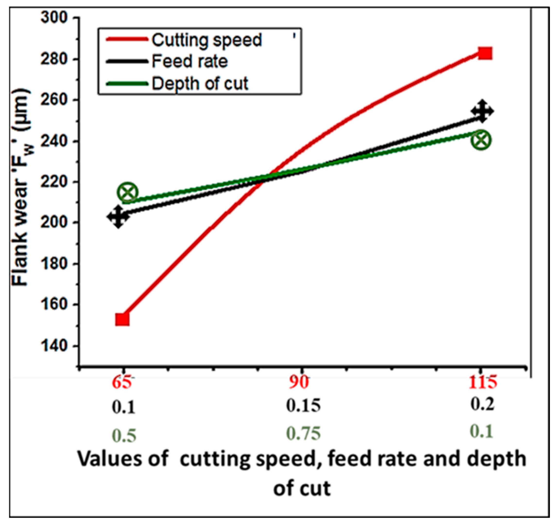
The graphical representation displayed in Figure 3 is used in this subsection to discuss the variation in flank wear ‘FW’ (µm) with cutting speed ‘Vc’, feed rate ‘f’, and depth of cut ‘ap’. The abscissa in these graphs depicts the values of the considered machining performance indicator, i.e., flank wear, whereas the ordinate depicts the levels of variable tuning parameters.
It can be observed in Figure 3 that the value of flank wear ‘Fw’ is increasing with all machining parameters. Compared with other variables, the cutting speed is more prominent, and the performance indicator (flank wear) increases linearly with the cutting speed. The value of flank wear is lower at low feed rates than at the lowest depth of cut; however, the variation in flank wear is greater at intermediate and higher feed rates compared with the depth of cut, as shown in Figure 3. It is evident that higher values of all variable parameters resulted in a rise in flank wear. The high cutting speed, feed, and depth of cut increased the rotational speed of the workpiece, tool movement corresponding to the workpiece, and chip thickness, respectively. As the feed rate and depth of cut increased, the undeformed chip section grew, resulting in more plastic deformation of the work material ahead of the cutting tool, which involved more energy to remove this area, and prominent frictional interaction at various contact interfaces [29,30]. Higher cutting speeds further intensified this effect as the deformation and interaction rate increased, which consequently converted the whole input energy to heat [31]. A high value of cutting speed significantly influenced the occurrence of tool wear and the formation of chips during turning of AZ31B magnesium alloy due to the generation of excessive heat, in addition to workpiece wobbling, vibration, and chattering [3].
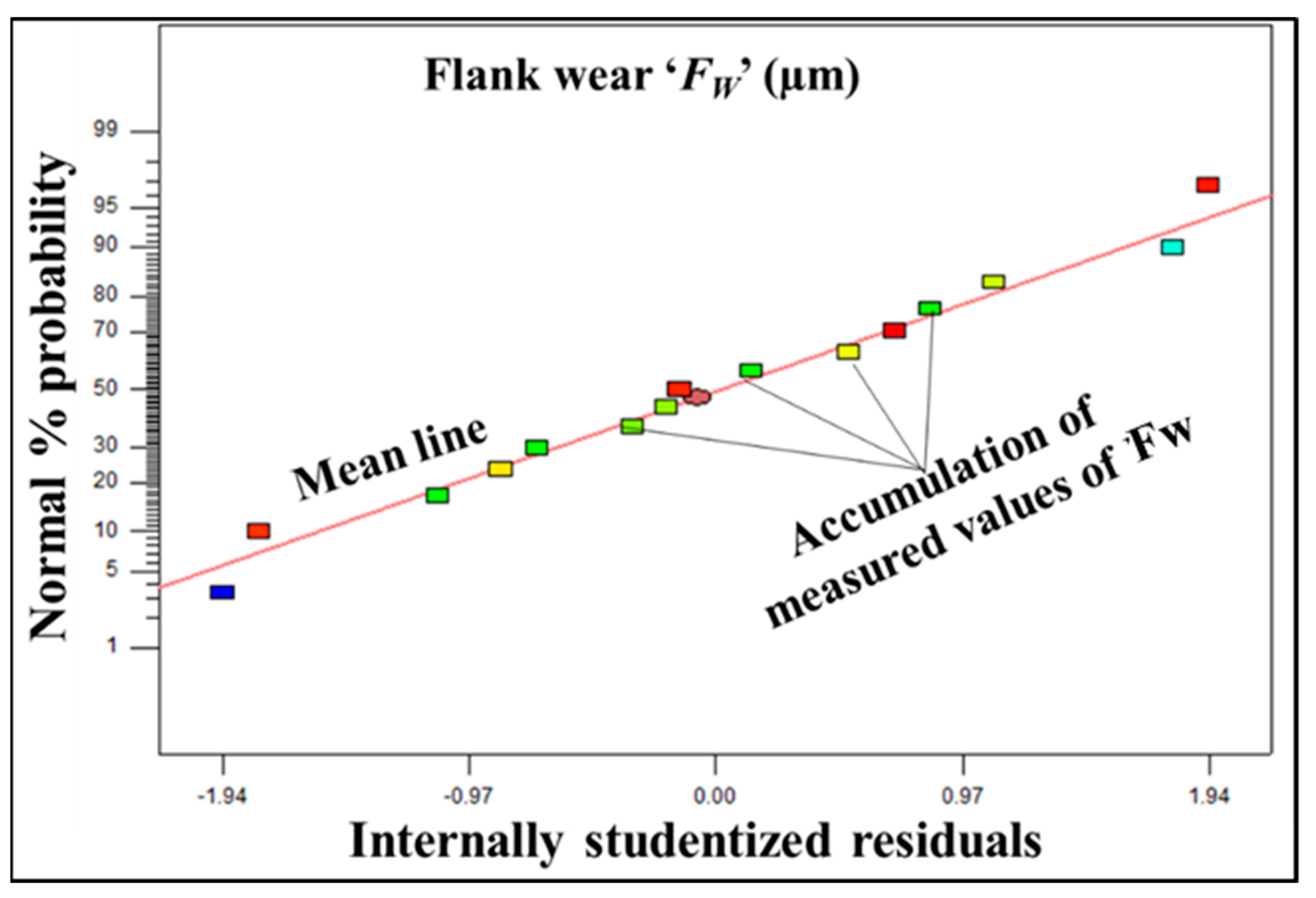
Figure 4 shows the normal probability plot of residuals for flank wear, which was drawn using the residual analysis as the main diagnostic tool. The graph demonstrates a normal distribution as the majority of the residuals gathered around a mean line, shown as a diagonal straight line in the graph. It can be observed that all fifteen residuals are accumulated around the mean line. Therefore, all fifteen residuals are concluded to be normally distributed for flank wear ‘FW’, as shown in Figure 4.

3.2. Tool Wear and Chip Morphology

Machining chip formation occurs when the material is removed from a base material known as a workpiece to bring it to the desired shape and size [32,33]. Chip formation is significantly influenced by cutting speed, feed rate, depth of cut, shape, material of tool insert, and workpiece material. In the context of the present investigation, cylindrical bars made of AZ31B magnesium alloy were machined in dry conditions. The optical and SEM images of the morphology of chips obtained at various turning combinations, i.e., at the highest flank wear (i.e., run 3), and lowest flank wear (i.e., run 12), are shown in Figure 5 and Figure 6, respectively. Band-saw-type chips were formed during the turning of AZ31B magnesium alloy using TiCn with a thin alumina-coated carbide tool insert, as shown in Figure 5 and Figure 6. Although magnesium alloys are classified as a soft material, a tendency to adhere its chips to the tool at the tool edge and rake face is a concern at higher cutting speeds in dry machining [34]. At high speed, the formation of continuous chips led to abrasive and adhesive wear as well as severe adhesion of magnesium on the tool flank face due to excessive temperature; at low speed, the formation of small and discontinuous chips led to some adhesion or chipping of magnesium particles on the tool flank face, and major wear occurred due to abrasion. Figure 5a and Figure 6a illustrate the formation of longer chips at a higher cutting speed (i.e., 115 m/min). Figure 5b and Figure 6b depict the formation of smaller and discontinuous chips at a low cutting speed (i.e., 65 m/min). Due to more intense plastic deformation and a greater thermal softening effect, the dense, irregular shear band chip formation is evident at a higher cutting speed (Figure 6a) [7]. The mild cracks have been observed to be formed on the chips’ back surfaces because there was no lubrication, which caused a lot of friction between the rake face of the cutting tool insert and the chips.
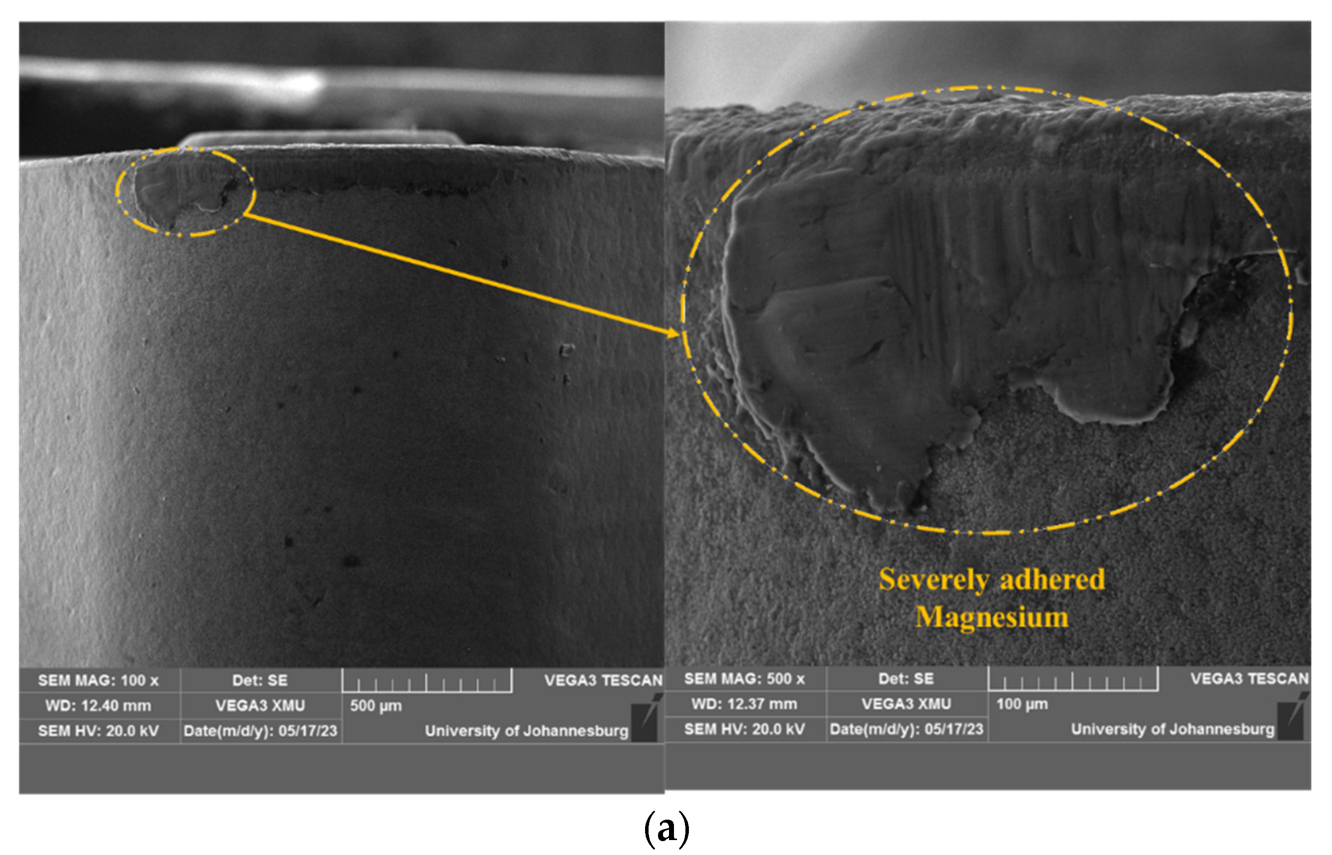
Figure 7 and Figure 8 present the scanning electron micrographs of tool wear. The SEM images, given in Figure 7, were obtained for the tool insert used at a high cutting speed, such as during experimental run 3, whereas Figure 8 shows the SEM images of tool wear for the machining conducted at low speed, such as in experimental run 12. From Figure 7, it is evident that tool wear is high at a high cutting speed due to the excessive chipping or adhesion of magnesium particles on the flank face of the tool (Figure 7a). The reason is the ignition of magnesium due to its softness at high-temperature generation due to the high frictional heat at a high cutting speed. Although we conducted preliminary experiments to avoid the ignition, some effect still exists. Some abrasion wear also occurred at the nose radius (Figure 7b) and a bit of tool material removal on the top of the flank face (Figure 7c). On the other hand, the tool wear at a low cutting speed is mainly due to abrasion only (Figure 8a–c). Since the heat generation, and therefore the adhesion and chipping, is low, few magnesium particles were found adhered on the tool flank face (Figure 8a,b). The nose radius also suffered from abrasion (Figure 8c).
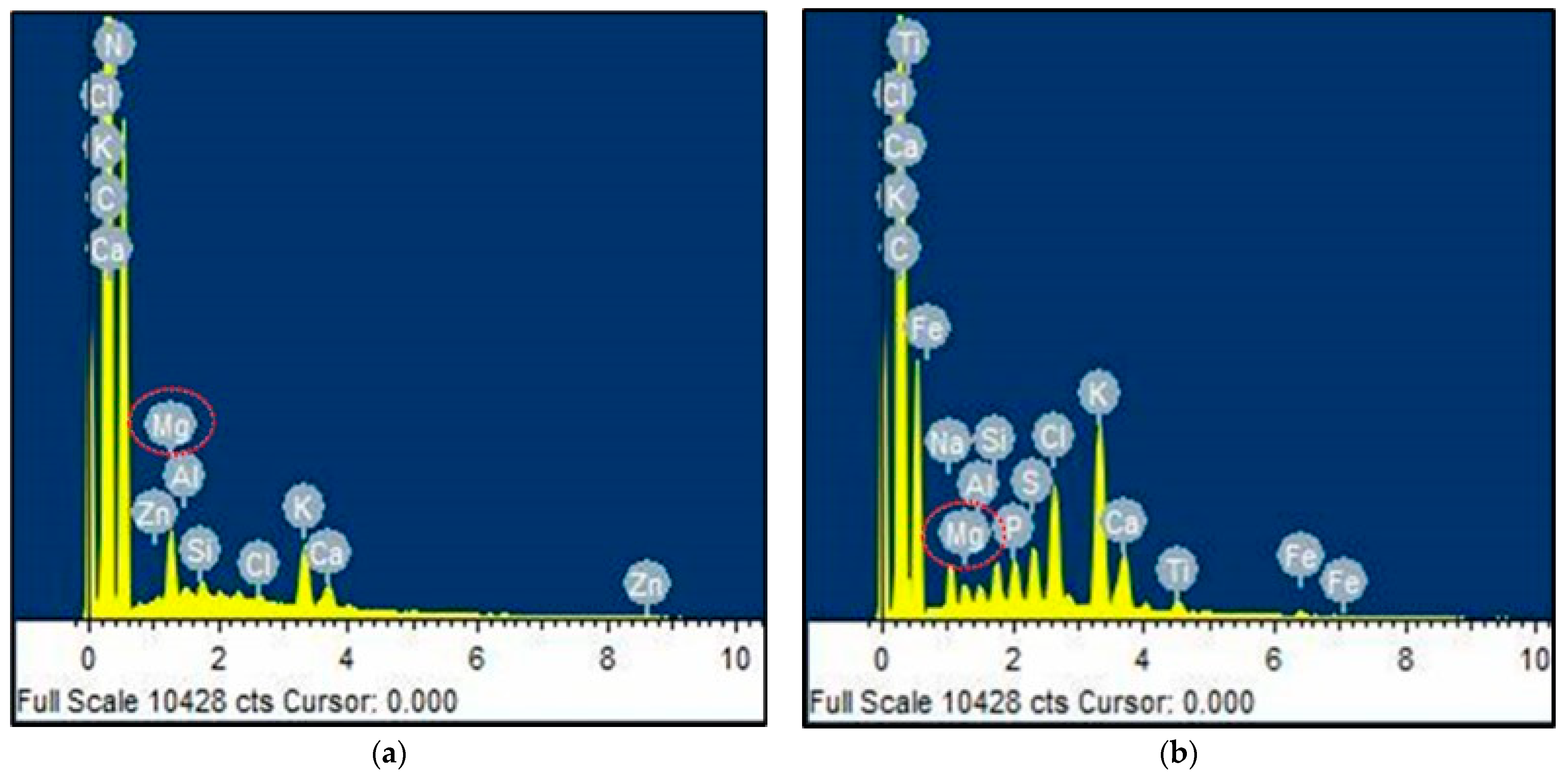
The elemental analysis of metallic samples was performed using the analytical method known as energy-dispersive X-ray spectroscopy (EDS). The EDS analysis reports, as presented in Figure 9, support the tool wear study. The adhesion of magnesium particles on the tool face at high speed and maximum tool wear, as shown in Figure 9a, is greater than the magnesium particles adhered on the tool face at low speed (Figure 9b).

4. Conclusions

In this study, AZ31B magnesium alloy was straight-turned in the dry environment using titanium carbonitride with thin alumina-coated carbide tool inserts at fifteen parametric cutting combinations based on BBD. A detailed study on the effect of machining parameters on tool flank wear, wear phenomenon, and chip morphology, have been conducted and reported. The major findings of this investigation can be summarized as follows:
  • Cutting speed influenced the flank wear most significantly.
  • Flank wear increased with the increase in cutting speed, feed rate, and depth of cut.
  • The formation of continuous chips while machining at a high cutting speed, and discontinuous and small chips at a low cutting speed, was observed.
  • The maximum flank wear value of 299.34 µm was obtained at a high cutting speed of 115 m/min and the minimum flank wear value of 89.56 µm at a low cutting speed of 65 m/min.
  • The main reason behind the high flank wear is the adhesion of work material, i.e., magnesium particles on the tool face, due to their ignition and deposition at high temperatures corresponding to high speed.
  • At low speeds, abrasion is the main wear mechanism with insignificant chipping of the work material.
  • In essence, for dry machining, it is recommended to machine magnesium alloy material at lower values of machining parameters to obtain better machinability and longer tool life.
Future research avenues may include the machining of AZ31B magnesium alloy with a combination of a dry environment and textured or treated tools, and a comparative study of magnesium machining under different cutting environments.

Author Contributions

Experimentation, measurement, validation, T.M.T. and S.K.C.; conceptualization, methodology, data curation, software, formal analysis, writing-original draft, S.K.C.; conceptualization, supervision, review, and editing, project administration, funding acquisition, K.G. All authors have read and agreed to the published version of the manuscript.

Funding

This research is supported by National Research Foundation (South Africa) under the NRF GRANT FOR 2023–2028: INCENTIVE FUNDING FOR RATED RESEARCHERS (IPRR), Grant No: 150892.

Data Availability Statement

The research data will be made available upon request.

Acknowledgments

Authors would like to acknowledge the technicians and lab staff of the department of mechanical and industrial engineering technology at the University of Johannesburg.

Conflicts of Interest

The authors declare no conflict of interest.

Appendix A

Table A1. Experimental results corresponding to machining parameter combinations.
Expt. No.Variable Machining ParametersResponses
Flank Wear ‘FW’ (µm)
Cutting Speed ‘Vc’ (m/min)Feed ‘f’ (mm/rev)Depth of Cut ‘ap’ (mm)R1R2Avg. (R1 + R2)
190 (0)0.15 (0)0.75 (0)258230244
265 (−1)0.20 (1)0.75 (0)192.5185.04188.77
3115 (1)0.15 (0)0.50 (−1)315.25283.43299.34
490 (0)0.10 (−1)1.00 (1)215.28192.16203.72
565 (−1)0.15 (0)1.00 (1)205.23175.51190.37
665 (−1)0.10 (−1)0.75 (0)137.26164.1150.68
790 (0)0.20 (1)0.50 (−1)252.32226.46239.39
8115 (1)0.15 (0)1.00 (1)306.21280.53293.37
990 (0)0.20 (1)1.00 (1)296.25285.21290.73
1090 (0)0.10 (−1)0.50 (−1)202.62222.12212.37
1190 (0)0.15 (0)0.75 (0)245.23213.45229.34
1265 (−1)0.15 (0)0.50 (−1)84.3294.889.56
13115 (1)0.20 (1)0.75 (0)294.4282.12288.26
14115 (1)0.10 (−1)0.75 (0)232.63272.31252.47
1590 (0)0.15 (0)0.75 (0)238.29224.97231.63
Table A2. Results of ANOVA for flank wear.
SourceSum of SquaresDFMean SquareF-Valuep-ValuePercentage ContributionRemarks
Model44,624.3394958.2611.170.0081 Significant
Vc33,032.21133,032.2174.400.000370.52Significant
f4413.7714413.779.940.02539.42Significant
ap2364.3112364.315.330.06915.05Not significant
Vc f1.3211.320.0029790.95860.00Not significant
Vc ap2850.4912850.496.420.05236.09Not significant
f ap899.701899.702.030.21391.92Not significant
(Vc2)1025.9011025.902.310.18902.19Not significant
(f2)10.97110.970.0250.88120.02Not significant
(ap2)0.09610.0960.00021620.98880.00Not significant
Residual2219.885443.98
Lack of fit2095.493698.5011.230.0829 Not significant
Pure error124.39262.20
Cor Total46,844.2114
R-Squared = 0.9526, Adjusted R-Squared = 0.8673, Predicted R-Squared = 0.2783
PRESS = 33,807.67, Adequate Precision = 11.62

References

  1. Dobrzanski, L.A.; Bamberger, M.; Totten, G.E. Magnesium and Its Alloys-Technology and Applications; CRC Press: Boca Raton, FL, USA, 2020. [Google Scholar]
  2. Moosbrugger, C. Engineering Properties of Magnesium Alloys; ASM International: Novelty, OH, USA, 2017. [Google Scholar]
  3. Thakur, B.; Barve, S.; Pesode, P. Investigation on mechanical properties of AZ31B magnesium alloy manufactured by stir casting process. J. Mech. Behav. Biomed. Mater. 2023, 13, 105641. [Google Scholar] [CrossRef] [PubMed]
  4. Abbas, A.; Huang, S.J.; Ballóková, B.; Sülleiová, K. Tribological effects of carbon nanotubes on magnesium alloy AZ31 and analyzing aging effects on CNTs/AZ31 composites fabricated by stir casting process. Tribol. Int. 2020, 142, 105982. [Google Scholar] [CrossRef]
  5. Dziubińskaa, A.; Gontarza, A.; Horzelskab, K.; Pieśko, P. The microstructure and mechanical properties of AZ31 magnesium alloy aircraft brackets produced by a new forging technology. Procedia Manuf. 2015, 2, 337–341. [Google Scholar] [CrossRef]
  6. Ugender, S.; Kumar, A.; Reddy, A.S. Microstructure and mechanical properties of AZ31B magnesium alloy by friction stir welding. Procedia Materi. Sci. 2014, 6, 1600–1609. [Google Scholar] [CrossRef]
  7. Zakaria, M.S.; Mustapha, M.; Azmi, A.I.; Khor, C.Y. Chip morphology and surface integrity in turning AZ31 magnesium alloy under dry machining and submerged convective cooling. Metals 2023, 13, 619. [Google Scholar] [CrossRef]
  8. Babe, I.B.; Gupta, K.; Chaubey, S.K. Sustainable dry machining of stainless steel with microwave-treated tungsten carbide cutting tools. Micromachines 2023, 14, 1148. [Google Scholar] [CrossRef] [PubMed]
  9. Wojtowicz, N.; Danis, I.; Monies, F.; Lamesle, P.; Chieragati, R. The influence of cutting conditions on surface integrity of a wrought magnesium alloy. Procedia Eng. 2023, 63, 20–28. [Google Scholar] [CrossRef]
  10. Viswanathan, R.; Ramesh, S. Optimization of machining parameters for magnesium alloy using Taguchi approach and RSM. Int. Conf. Adv. Des. Manuf. 2014, 2, 1–534. [Google Scholar]
  11. Yalçın, B.; Özileri, E.D. Experimental investigation on turning of casted magnesium alloy used in manufacturing automotive parts. In Proceedings of the Advances in Materials & Processing Technologies Conferences, Madrid, Spain, 14–17 December 2015. [Google Scholar]
  12. Kolluru, U.K.; Narala, S.K.R.; Dutta, S. Optimization of cutting forces and surface roughness in dry turning of AM magnesium alloy using Taguchi method. Mater. Today Proc. 2021, 38, 2830–2838. [Google Scholar] [CrossRef]
  13. Gao, H.; Ma, B.; Singh, R.P.; Yang, H. Areal surface roughness of AZ31B magnesium alloy processed by dry face turning: An experimental framework combined with regression analysis. Materials 2020, 13, 2303. [Google Scholar] [CrossRef]
  14. Rubio, E.M.; Valencia, J.L.; Saá, A.J.; Carou, D. Experimental study of the dry facing of magnesium pieces based on the surface roughness. Int. J. Precis. Eng. Manuf. 2013, 14, 995–1001. [Google Scholar] [CrossRef]
  15. Guo, X.; Teng, L.; Wang, W.; Chen, T. Study on the cutting properties of magnesium alloy when dry turning with titanium cutting tools. Adv. Mater. Res. 2010, 102–104, 653–657. [Google Scholar] [CrossRef]
  16. Deswal, N.; Kant, R. Machinability and surface integrity analysis of magnesium AZ31B alloy during laser assisted turning. J. Manuf. Process. 2023, 101, 527–545. [Google Scholar] [CrossRef]
  17. Ali, S.; Pervaiz, S. Machinability analysis of AZ31 magnesium alloys using the Taguchi gray relational analysis. Int. J. Adv. Manuf. Technol. 2023, 126, 4171–4190. [Google Scholar] [CrossRef]
  18. Deshwal, N.; Kant, R. Experimental investigation on magnesium AZ31B alloy during ultrasonic vibration assisted turning process. Mater. Manuf. Process. 2022, 37, 1–7. [Google Scholar] [CrossRef]
  19. Zakaria, M.S.; Mustapha, M.; Azmi, A.I.; Ahmad, A.; Danish, M.; Rubaiee, S. Machinability investigations of AZ31 magnesium alloy via submerged convective cooling in turning process. J. Mater. Res. Technol. 2022, 19, 3685–3698. [Google Scholar] [CrossRef]
  20. Ijaz, H.; Asad, M.; Danish, M.; Gupta, M.K.; Siddiqui, M.E. Al-Zahrani, Numerical investigations of cutting temperature and cutting forces in cryogenic assisted turning of magnesium alloy. Int. J. Adv. Manuf. Technol. 2021, 114, 1991–2001. [Google Scholar] [CrossRef]
  21. Viswanathan, R.; Ramesh, S.; Maniraj, S.; Subburam, V. Measurement and multi-response optimization of turning parameters for magnesium alloy using hybrid combination of Taguchi-GRA-PCA technique. Measurement 2020, 159, 107800. [Google Scholar] [CrossRef]
  22. Dutta, S.; Narala, S.K.R. Optimizing turning parameters in the machining of AM alloy using Taguchi methodology. Measurement 2021, 169, 108340. [Google Scholar] [CrossRef]
  23. Asal, O. Optimization of Surface Roughness in Turning of AZ31 Magnesium Alloys with Taguchi Method. Gazi Univ. J. Sci. Part A Eng. Innov. 2019, 6, 25–32. [Google Scholar]
  24. Tibrewal, V.; Dak, K.; Himanshu, A.; Kumar, H.; Kuppan, P.; Balan, A.S.S. Cryogenic Machining of AZ31B Magnesium Alloy for Bio-implant Applications. In Advances in Forming, Machining and Automation. AIMTDR 2018. Lecture Notes on Multidisciplinary Industrial Engineering; Shunmugam, M.S., Kanthababu, M., Eds.; Springer: Singapore, 2019. [Google Scholar] [CrossRef]
  25. Danish, M.; Ginta, T.L.; Habib, K.; Carou, D.; Rani, A.M.A.; Saha, B.B. Thermal analysis during turning of AZ31 magnesium alloy under dry and cryogenic conditions. Int. J. Adv. Manuf. Technol. 2017, 91, 2855–2868. [Google Scholar] [CrossRef]
  26. Urbikain, G.; Olvera, D.; de Lacalle, L.N.L.; Elías-Zúñiga, A. Stability and vibrational behaviour in turning processes with low rotational speeds. Int. J. Adv. Manuf. Technol. 2015, 80, 871–885. [Google Scholar] [CrossRef]
  27. Pathak, S. Intelligent Manufacturing, 1st ed.; Springer: Cham, Switzerland, 2022. [Google Scholar]
  28. Montgomery, D.G. Design and Analysis of Experiments, 7th ed.; John Willey and Sons: New York, NY, USA, 2009. [Google Scholar]
  29. Kant, G.; Sangwan, K.S. Prediction and optimization of machining parameters for minimizing power consumption and surface roughness in machining. J. Clean. Prod. 2014, 83, 151–164. [Google Scholar] [CrossRef]
  30. Sahoo, S.P.; Datta, S. Dry machining of Ti–6Al–4V using PVD Si-doped TiAlxN super nitride (HSN2) coated WC–Co tool. J. Braz. Soc. Mech. Sci. Eng. 2022, 44, 1–23. [Google Scholar] [CrossRef]
  31. Ramachandran, K.; Yeesvaran, B.; Kadirgama, K.; Ramasamy, D.; Ghani, S.A.C.; Anamalai, K. State of art of cooling method for dry machining. MATEC Web Conf. 2016, 90, 1–8. [Google Scholar] [CrossRef]
  32. Suresh, R.; Basavarajappa, S.; Gaitonde, V.N. Experimental studies on the performance of multilayer coated carbide tool in hard turning of high strength low alloy steel. J. Mater. Res. 2015, 30, 3056–3064. [Google Scholar] [CrossRef]
  33. Kotiba, H. Highly-Ductile Magnesium Alloys: Atomistic-Flow Mechanisms and Alloy Designing. Materials 2019, 12, 1934. [Google Scholar]
  34. Yuan, J.; Fox-Rabinovich, G.S.; Veldhuis, S.C. Control of tribofilm formation in dry machining of hardened AISI D2 steel by tuning the cutting speed. Wear 2018, 402–403, 30–37. [Google Scholar] [CrossRef]
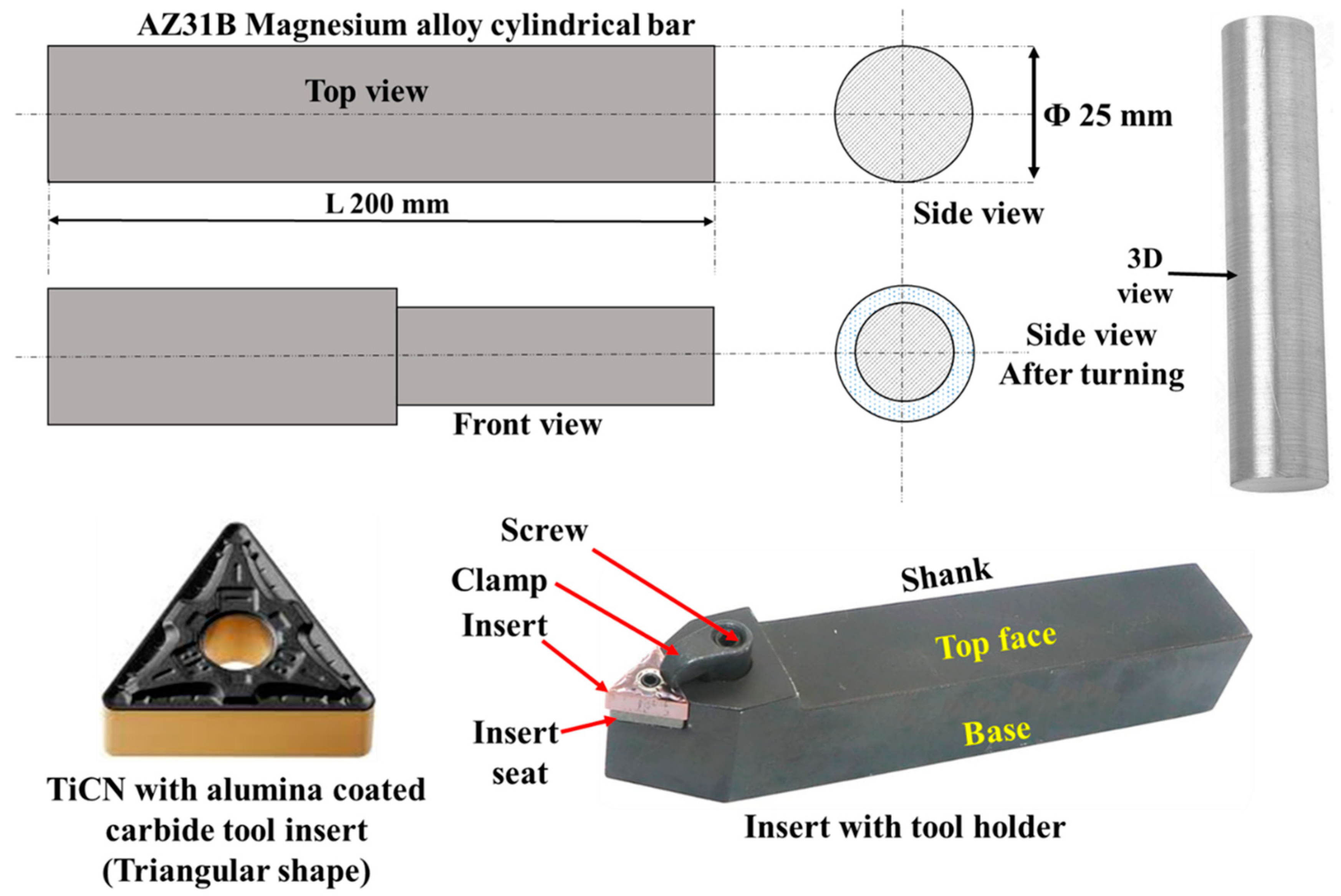
Figure 1. Work material magnesium alloy bar and tool insert used in the present study.
Jmmp 07 00187 g001
Figure 2. Sequence of steps involved during turning of AZ31B magnesium alloy bar using coated carbide tool insert.
Jmmp 07 00187 g002
Figure 3. Variation of tool flank wear with machining parameters.
Jmmp 07 00187 g003
Figure 4. Normal probability distribution graphs of residuals for flank wear ‘FW’.
Jmmp 07 00187 g004
Figure 5. Optical images of chip morphology at (a) Vc: 115 m/min, f: 0.15 mm/rev, ap: 0.5 mm; (b) Vc: 65 m/min, f: 0.15 mm/rev, ap: 0.5 mm.
Jmmp 07 00187 g005
Figure 6. SEM images of chip morphology at (a) Vc: 115 m/min, f: 0.15 mm/rev, ap: 0.5 mm; (b) Vc: 65 m/min, f: 0.15 mm/rev, ap: 0.5 mm.
Jmmp 07 00187 g006
Figure 7. SEM micrographs of tool wear in experimental run 3. Vc: 115 m/min, f: 0.15 mm/rev, ap: 0.5 mm.
Jmmp 07 00187 g007aJmmp 07 00187 g007b
Figure 8. SEM micrographs of tool wear in experimental run 12. Vc: 65 m/min, f: 0.15 mm/rev, ap: 0.5 mm.
Jmmp 07 00187 g008
Figure 9. EDS analysis report of cutting tool insert used for machining: (a) maximum adhesion of magnesium particles at high speed (Vc: 115 m/min); (b) minimum adhesion of magnesium particles at low speed (Vc: 65 m/min).
Jmmp 07 00187 g009
Table 1. Description of selected machining parameters, specifications of the workpiece and cutting tool, and composition of workpiece material.
Parameters Varied during the TurningMachining Performance Indicators/Responses
Parameters, Symbols, and
(Unit)
Levels (Actual and (Coded))
Low (−1)Medium (0)High (1)
Cutting speed ‘Vc’ (m/min)65 (−1)90 (0)115 (1)Flank wear (FW)
Chip morphology
Feed rate ‘f’ (mm/rev)0.1 (−1)0.15 (0)0.2 (1)
Depth of cut ‘ap’ (mm)0.5 (−1)0.75 (0)1.0 (1)
Constant machining factors
Workpiece diameter, materials of inserts and workpiece; cutting tool inserts; tool geometry; turning time (15 min); Mode of machining: dry
Details of the machine, workpiece, and cutting tool
Machine detailsMake: Colchester, Model: Mascot 1600, Country of origin: UK; Power: 12.5 HP; Maximum RPM: 1600
Workpiece details Material: Magnesium alloy (AZ31B); Shape: Cylindrical bar; Cross-section: Round; Dimensions: diameter (ф)—25 mm, Length (l)—200 mm
Cutting tool detailsMaterial: Tungsten carbide; Type: Insert; Shape: Triangular; Cutting edges: 3, Type: Single point (Negative); Hardness: 3000 HV
Chemical composition (% wt.) of Mg work materialMg: 96.5%; Al: 2.5; Zn: 0.6; Mn: 0.2; Si: 0.1; Cu: 0.05; Ca: 0.04; Fe: 0.005; Ni: 0.005
Physical and Mechanical properties of the magnesium alloy barDensity: 1.77 g/cm3; Tensile strength: 260 MPa; Compressive strength: 97 MPa; Elastic modulus: 44.8 GPa; Poisson’s ratio: 0.35
Disclaimer/Publisher’s Note: The statements, opinions and data contained in all publications are solely those of the individual author(s) and contributor(s) and not of MDPI and/or the editor(s). MDPI and/or the editor(s) disclaim responsibility for any injury to people or property resulting from any ideas, methods, instructions or products referred to in the content.