Article

Hot-Air Contactless Single-Point Incremental Forming

1
Department of Mechanical Engineering, University of Birmingham, Edgbaston, Birmingham B15 2TT, UK
2
Department of Mechanical Engineering Technology, Yanbu Industrial College, Yanbu Al-Sinaiyah 41912, Saudi Arabia
3
School of Engineering, Technology, and Design, Canterbury Christ Church University, Canterbury B15 2TT, UK
*
Author to whom correspondence should be addressed.
J. Manuf. Mater. Process. 2023, 7(5), 179; https://doi.org/10.3390/jmmp7050179
Submission received: 22 August 2023 / Revised: 25 September 2023 / Accepted: 26 September 2023 / Published: 5 October 2023

Abstract

:
Single-point incremental forming (SPIF) has emerged as a time-efficient approach that offers increased material formability compared to conventional sheet-metal forming techniques. However, the physical interaction between the forming tool and the sheet poses challenges, such as tool wear and formability limits. This study introduces a novel sheet-forming technique called contactless single-point incremental forming (CSPIF), which uses hot compressed air as a deformation tool, eliminating the requirement for physical interaction between the sheet and a rigid forming tool. In this study, a polycarbonate sheet was chosen as the case-study material and subjected to the developed CSPIF. The experiments were carried out at an air temperature of 160 °C, air pressure of 1 bar, a nozzle speed of 750 mm/min, and a step-down thickness of 0.75 mm. A Schlieren setup and a thermal camera were used to visualize the motion of the compressed hot air as it traveled from the nozzle to the sheet. The results showed that the CSPIF technique allowed for the precise shaping of the polycarbonate sheet with minimal springback. However, minor deviations from the designed profile were observed, primarily at the starting point of the nozzle, which can be attributed to the bending effects of the sample. In addition, the occurrence of sheet thinning and material buildup on the deformed workpiece was also observed. The average surface roughness (Ra) of the deformed workpiece was measured to be 0.2871 microns.

1. Introduction

In the past decade, the manufacturing industry has seen significant changes driven by the growing need for product customization and the integration of Industry 4.0 technologies. 3D printing, a key Industry 4.0 technology, has revolutionized work processes and increased the demand for advanced manufacturing techniques, especially for small-batch custom products. One crucial process for small to medium-sized customized sheet-material production is single-point incremental forming (SPIF) [1]. This cost-effective technology allows for the creation of highly customized shapes and components in a single step from metal sheets, without the need for dedicated dies. SPIF, utilizing computer numerically controlled (CNC) technology, offers high precision and accuracy, enabling the production of complex shapes with reduced lead time and low forming forces, resulting in high formability. These advantages align perfectly with the adaptable and flexible manufacturing processes required by Industry 4.0 [2].
Since its introduction in Matsubara labs in Japan by Leszak et al. [3], single-point incremental forming (SPIF) has seen significant advancements and widespread adoption in various industries. Notably, it plays a crucial role in aerospace, where it achieves precision shaping of Ti–6Al–4V alloy [4,5], in automotive manufacturing for customized parts from steel and aluminum alloys [6], and in the medical field for biomedical implant production [7]. SPIF, however, presents challenges, including elastic springback, which can compromise geometric precision and final component shape. Material thinning during sheet forming can also reduce product precision, but optimizing parameters like feed rate, tool path, and tool speed can enhance shape precision, minimize defects, and improve geometry accuracy [8]. The use of edge stiffeners [9] and multistage incremental forming [10,11] can further enhance precision. Another issue is poor surface finish, impacting aesthetics and mechanical properties due to the incremental nature of the process. Surface quality depends on factors such as spindle speed, forming tool radius, vertical increment, and feeding rate. Taguchi methods can help optimize settings and identify key factors affecting surface roughness [12]. High tool wear is a significant limitation, caused by repeated tool–material contact, leading to increased costs due to frequent replacements. Reducing tool wear in SPIF involves adjusting sheet-metal properties, optimizing process parameters, and using coolants and lubricants [13,14,15].
In SPIF research, the initial focus has been on metallic materials, but there is now growing interest in exploring other materials like polymers, thermoplastics, and composites. Shifting from metals to polymers shows promise for future SPIF technology development [16]. These materials, although challenging to shape, have diverse applications, and SPIF provides a solution to traditional polymer processing problems. Furthermore, SPIF’s mold-free process allows the cost-effective production of small batches and unique parts [17]. Additionally, localized deformations by SPIF enable the creation of objects from a variety of thermoplastics, from polyethylene [18] to polycarbonate, all at ambient temperatures [19].
During SPIF of polymers, heat is often used to reduce the strength, which can enhance the formability of brittle polymers using various heating methods. These methods raise the forming temperature of the metal and thermoplastic sheets [20,21]. For example, Ambrigio et al. [22] employed a similar heating system for forming PMMA sheets using ISF. On the other hand, Conte et al. [23] used a 2 kW heater within an insulated chamber within a refractory-coated metallic structure Okada et al. [24] employed a halogen lamp to heat and deform a thermoplastic CFRP sheet, while in another study a heating coil is used to heat a PC sheet of an SPIF process [25].
In SPIF of polymers, three main failure modes can occur. First, there can be an in-plane fracture caused by ductile tearing, where the inclined wall meets the corner of the formed part in the circumferential direction because of the stress buildup. Second, wrinkles can form adjacent to the inclined wall of the formed part near the corner due to twisting of the workpiece due to the solid forming tool [19]. It was found that the SPIF of polymers has a more pronounced springback than metals [26]. Durante et al. [19] showed that the tool design affects the amount of springback in the forming process, while the toolpath strategy does not have a significant effect. Bagudanch et al. [27] found that applying heat to the workpiece after forming reduces springback. Decreasing the initial drawing angle, increasing the original sheet thickness, and reducing the step size can also decrease springback.
Achieving a satisfactory surface finish in polymer-forming processes, similar to SPIF in metal forming, faces challenges due to springback in polymer sheets and the incremental SPIF process. Lubricants like grease and liquid types reduce tool friction, enhancing surface quality. Forming settings, such as spindle speed and tool parameters, influence material roughness [28]. A roller ball tool can also improve surface finish [29], especially at lower temperatures. Tool material, geometry, and paths also impact surface quality [30].
Despite polymer SPIF advancements, issues like geometric precision, wrinkling, tool wear, and rough surfaces persist due to tool-polymer interaction. To combat tool wear, Water Jet Incremental Sheet Forming (WJISF) emerges, originating from water jet cutting. This is promising for automotive, micro-electronics, medical, and aerospace industries, requiring a multi-axial machine and pressure pump. Environmentally friendly with water recycling and no lubricants, WJISF warrants more research in terms of complex shapes and different alloys [31].
This research aimed to develop another contactless single-point incremental forming, which uses hot compressed air as a deforming tool without any physical contact. The goal of this process is to eliminate the physical interaction between the tool and the polymeric material, therefore reducing defects and lowering the cost of rigid tool production and lubricants. The experimental findings, deformation behavior, and workability of this new process are evaluated using polycarbonate as a demonstration material, and its design is described.

2. Materials and Methods

2.1. Design of the Contactless Incremental Point Forming

The hot-air contactless single-point incremental forming process is based on traditional single-point incremental forming, but with a difference—it uses pressured hot air rather than a rigid tool. In the traditional SPIF process, a clamping mechanism is used to hold the polymer or metal sheet securely in place. The material is then deformed using a rigid forming tool, which is driven by a control system to move along a predetermined path and shape the sheet into the desired form. Figure 1b shows a schematic of the contactless single-point incremental forming process. Similar to traditional SPIF, a clamping frame is used to clamp the workpiece. A nozzle supplied with a controlled-temperature hot-air nozzle is used to deform the workpiece according to the programmed CNC code.
The design of the HASPIF setup involves several key components, including five-bar air compressors, an in-line air and gas heater pipe, a PID temperature controller, a single-phase SSR, a 5 mm hose, an electric vacuum, and a 3D coordinate controller, which is implemented using a 3D printer setup; see Figure 1b,c. All these elements are essential in ensuring the smooth and efficient operation of the system. For example, the 3D coordinate controller setup is used to control the movement and speed of the nozzle, while a specially built steel fixture is used to clamp the sheet in place and prevent material flow into the forming area. Additionally, the air compressor is linked to the in-line gas heater pipe through an 8.5 mm hose and provides compressed air to the heater, which in turn heats the air and maintains a consistent temperature using a thermocouple and SSR relay connected to the PID temperature controller. The inlet of the heater is connected to the hose through a ¾” female × 3/8” push fit, and the thermocouple is attached at the exit of the heater for hot-air temperature measurement. The electric connection of the heater and the thermocouple is managed by the SSR relay, which is connected to the temperature controller to maintain the required temperature. Finally, a stainless-steel nozzle, with a 33 mm inlet diameter and 5 mm outlet diameter, has been designed and implemented at the outlet of the heater to further regulate the flow of air and gas.

2.2. Nozzle Design and Manufacturing

The aim of the nozzle design is to develop a nozzle that can apply pressure to a polymer material without having physical contact with it. This is crucial because direct contact can negatively affect the polymer’s quality. To attain this objective, the nozzle must generate a precisely controlled flow of pressurized air, producing a force on the polymer material while avoiding direct contact. Additionally, the nozzle must be able to manage the elevated temperatures and pressures that come with delivering pressurized air from a compressor and air heater. To meet this requirement, the nozzle needs to be made of moderate-temperature materials like alloy steel.
SolidWorks was used to create the CAD model of the nozzle, which included the reducer, the inlet, and the outlet, see Figure 2a. The nozzle has been specifically designed to accommodate a thermocouple, which enables the measurement of the high-temperature compressed air flowing through the nozzle. To facilitate the attachment of the thermocouple, a small aperture has been created on the upper side of the nozzle, beneath the thread that runs from the outer chamber to the inner chamber. The hole was then sealed to create a pathway for the thermocouple to reach the inlet of the nozzle. This design allowed for the accurate measurement and management of the temperature of the hot compressed air at the inlet of the nozzle. The ability to measure the temperature provided valuable information about the inlet temperature of the hot air that is used to deform the polymer sheet.
The alloy steel nozzle was produced using a metal laser powder bed fusion printer (Concept Laser-M2 cusing). The 3D metal printer has a continuous wave ytterbium fiber laser with a nominal laser power of 200 W. The built chamber is maintained in a controlled argon atmosphere, ensuring a safe and controlled environment during the 3D printing. The material used in the fabrication process was the gas-atomized steel powders from Concept Laser. The fabricated nozzle is shown in Figure 2b.

2.3. Sheet Material

The polymeric material for this project was Lexan® 9030 polycarbonate (PC) with dimensions of 205 mm length, 170 mm width, and 0.75 mm thickness. As depicted in Table 1, the properties of this PC sheet boast high impact resistance, transparency, and temperature stability. To fully comprehend the behavior of the PC sheet under varying temperatures, stress and strain curves were analyzed from room temperature to 160 °C. These curves, which demonstrate the correlation between temperature and mechanical properties of the PC sheet, were sourced from previous research studies [32,33]. The literature shows that, at temperatures that exceed the glass transition temperature threshold, strain hardening disappears. As a result, a forming temperature of 160 °C was utilized for the CSPIF process.
The path, shaped like a truncated pyramid, was created using consecutive parallel loops. It commenced with a 152 mm × 120 mm rectangle in the initial loop. Each loop rectangle decreases by 5 mm from each side and concludes with a 62 mm × 30 mm rectangle in the last loop, with each loop step-down of 0.75 mm. As illustrated in Figure 3b, the initial trajectory follows a straight path in both clockwise directions, denoted as “1” and “2”, until it returns to its starting point. Subsequently, it shifts along the x and z-axis, as indicated by direction “3”, before proceeding in “4” direction along the y-axis to initiate the subsequent descent. This movement pattern continues until the last path.

2.4. Process Parameters

The contactless process of deformation relied on five parameters, including air pressure, air temperature, nozzle speed, the gap between the nozzle and the polymer sheet, and step-down thickness, which are outlined in Table 2. These parameter choices were influenced by the most efficient parameters used in the conventional SPIF process, particularly the feed rate and step-down, in conjunction with those relevant to the new tool. Additionally, new parameters, including air pressure, air temperature, and initial gap, were introduced through experimental determination to optimize the performance of the newly implemented hot compressed air tool.
The process began with the activation of the air heater and the adjustment of its temperature to 160 °C, as specified by the controller. The air compressor was then turned on to deliver compressed air with a pressure of 1 bar to an 8.5 mm plastic hose. One end of the hose was attached to the air compressor and the other end was attached to the air heater. As the compressed air flowed through the heating element inside the heater, it was heated to the required temperature. The hot compressed air was then directed to the nozzle located at the outlet of the heater. When the nozzle was used, it increased the velocity of the air, which resulted in an increased forming force and the concentration of pressure in a specific area of the polycarbonate sheet. This prevented the occurrence of friction force that could have resulted from the use of a conventional tool tip during the deformation process. Using compressed air as the forming force instead of a solid tool significantly reduced the risk of surface fractures or wear tracks on the polycarbonate.

2.5. Visualization of the Air Flow

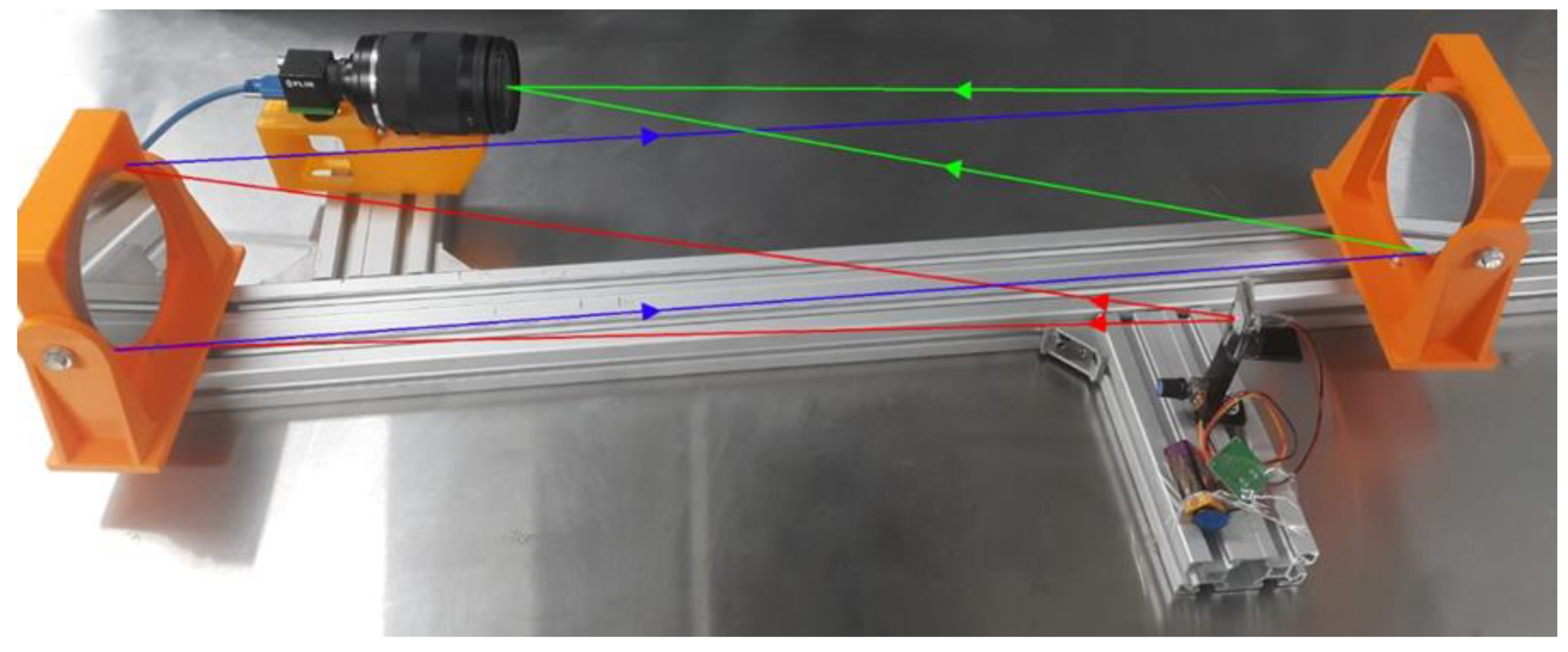
An RS T-10 smart thermal camera was used to capture the thermal images and compare the result of the temperature that heated the nozzle itself with the value of the temperature on the PC sheet during the deformation. Conversely, A Z-type Schlieren setup was employed to visualize the airflow from the nozzle to the polymer sheet [34]. It comprised two concave mirrors, a spotlight serving as the light source, and a razor edge; see Figure 4. In addition, the setup included a digital single-lens reflex (DSLR) camera. The red lines in the setup indicate the light emitted from the LED pinhole; the blue lines indicate the parallel lights between the mirrors; and the green light represents the light that reaches the focal point.
The Schlieren setup was utilized to observe the motion of the hot compressed air as it traveled from the nozzle to the polymer sheet. The configuration of the system was such that the hot compressed reducer was positioned in the center, the nozzle was directed downwards, and the camera was equipped with a 100 mm micro lens. To attain optimal image quality, the Schlieren system underwent calibration using a high-density gradient-producing candle. To enhance the image, the light and razor edge were positioned at one focal length from the mirror direction. The camera was positioned beneath the razor edge. A gap of 6mm was maintained as the hot compressed air was expelled from the nozzle towards the polymer sheet. The temperature and pressure of the hot air inside the nozzle were found at 160 °C and 1 bar, respectively. The camera was positioned in such a way that it captured the movement of the hot air as it emerged from the nozzle and made contact with the sheet below it.

3. Results and Discussion

3.1. Forming Force and Air Thermal Flow

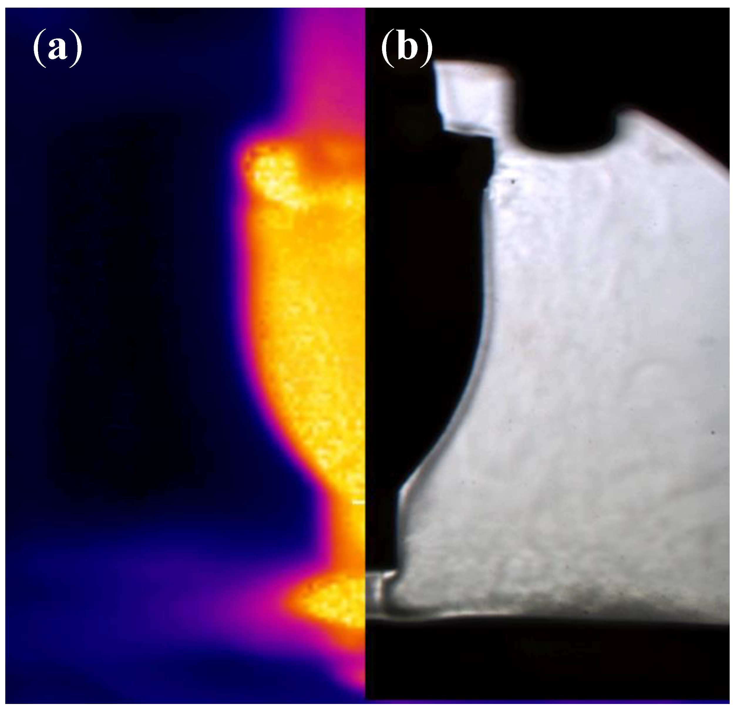
The airflow from the compressed air nozzle has a significant impact on the proposed forming process. The high-pressure air coming out of the nozzle creates a thrust that is used to deform the PC (polycarbonate) sheet. The axial (z-axis) force during the incremental forming process was measured by calculating the value of the air pressure and the affected area on the PC sheet. The pressure input of the nozzle was adjusted at 1 bar, and the affected area was determined using the results of the thermal and Schlieren images. Based on the affected area, the forming force was calculated to be 2.17 N, which is a rather small amount, taking into account the inlet pressure. However, this small forming force is sufficient to deform a polycarbonate sheet when combined with an elevated temperature. The results of the thermal image shown in Figure 5a show that the temperature-affected area diameter was equal to 18.67 mm (an area equal to 273.77 mm2) while the pressure zone diameter from the Schlieren image was equal to 5.26 mm (an area equal to 21.73 mm2) in Figure 5b in an open-air system, the pressure drops significantly right after the air leaves the nozzle tip. However, the temperature does not decrease at the same rate, which results in variations in the affected areas measured by the thermal camera and those by the Schlieren. Figure 5b shows the hot compressed air flow coming out of the nozzle. Moreover, the affected area on the sheet from the air is obvious. As a result, the diameter of the affected area on the sheet is equal to 6 mm when comparing that area with the outlet diameter of the nozzle (5 mm).

3.2. Geometric Profile of the PC Workpiece

The precision and accuracy of the deformed workpiece fabricated using the proposed contactless incremental forming technique were determined using a Mitutoyo coordinate measuring machine, the Euro-CA776 (CMM), with an accuracy of (1.7 + 0.3 L/100) µm. The measuring strategy employed involved sensing discrete points using a trigger probe positioned along the cross-section of the workpiece, from one edge to the other. The coordinates for each point were determined from both the top and bottom sides. The top-side measurements provided the profile data, while measurements of the bottom side were used to calculate the sheet thickness on the surface. The CMM was used to calculate the profile and thickness of the deformed part and compare it to the target geometry.
Figure 6 illustrates the comparison between the CAD drawing and the measured profile after being fabricated using CSPIF. The CAD drawing profile data were obtained using SolidWorks by generating a G-code of the path from the edge to the middle. To ensure the validity of the results, the profiles obtained through experimentation were measured by scanning the workpiece using a CMM, eliminating any unclamping and cooling errors and ensuring an accurate assessment of the precision of the proposed method.
As shown in Figure 6, observations made before unclamping revealed minimal springback at the base of the pyramid and a pillow effect in the center. The results suggest that the CIPF system can deform polycarbonate sheets accurately. The obtained profile formed at 160 °C closely resembles the CAD design drawing profile, which demonstrates the effectiveness of the proposed technology.
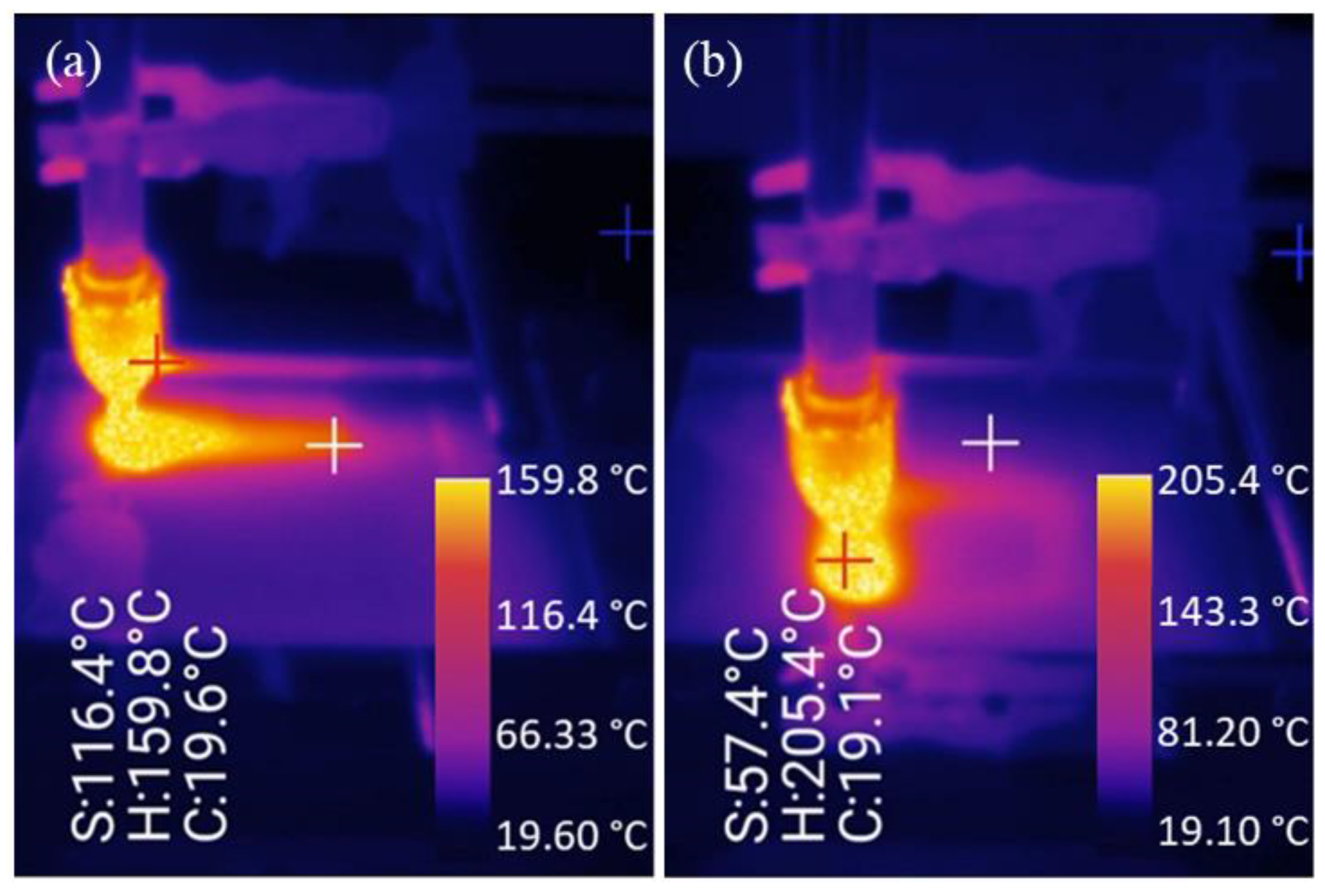
Additionally, the bending effect at the nozzle starting point produces a deviation from the ideal profile as the PC sheet is being deformed. This deviation between the digital model and the deformed workpiece or the error in manufacturing has a significant impact on the final product’s quality and accuracy, especially when working with precision parts [35,36]. To mitigate these effects, it is crucial to consider the fixture design, nozzle placement, and the starting position of the nozzle thermal when performing the deformation process. Moreover, the use of the RS T-10 smart camera enabled the monitoring of the temperature distribution during the deformation process, which was crucial to understanding the reasons behind the deviation from the ideal profile. The temperature reached a maximum of 205 °C at the overlapped areas, where the heat tails intersected, highlighting the significance of temperature control in the deformation process; see Figure 7. Proper consideration of fixture design, nozzle placement, and starting position of the nozzle is essential to prevent overlapping and minimize deviation from the desired profile.

3.3. Thickness Distribution

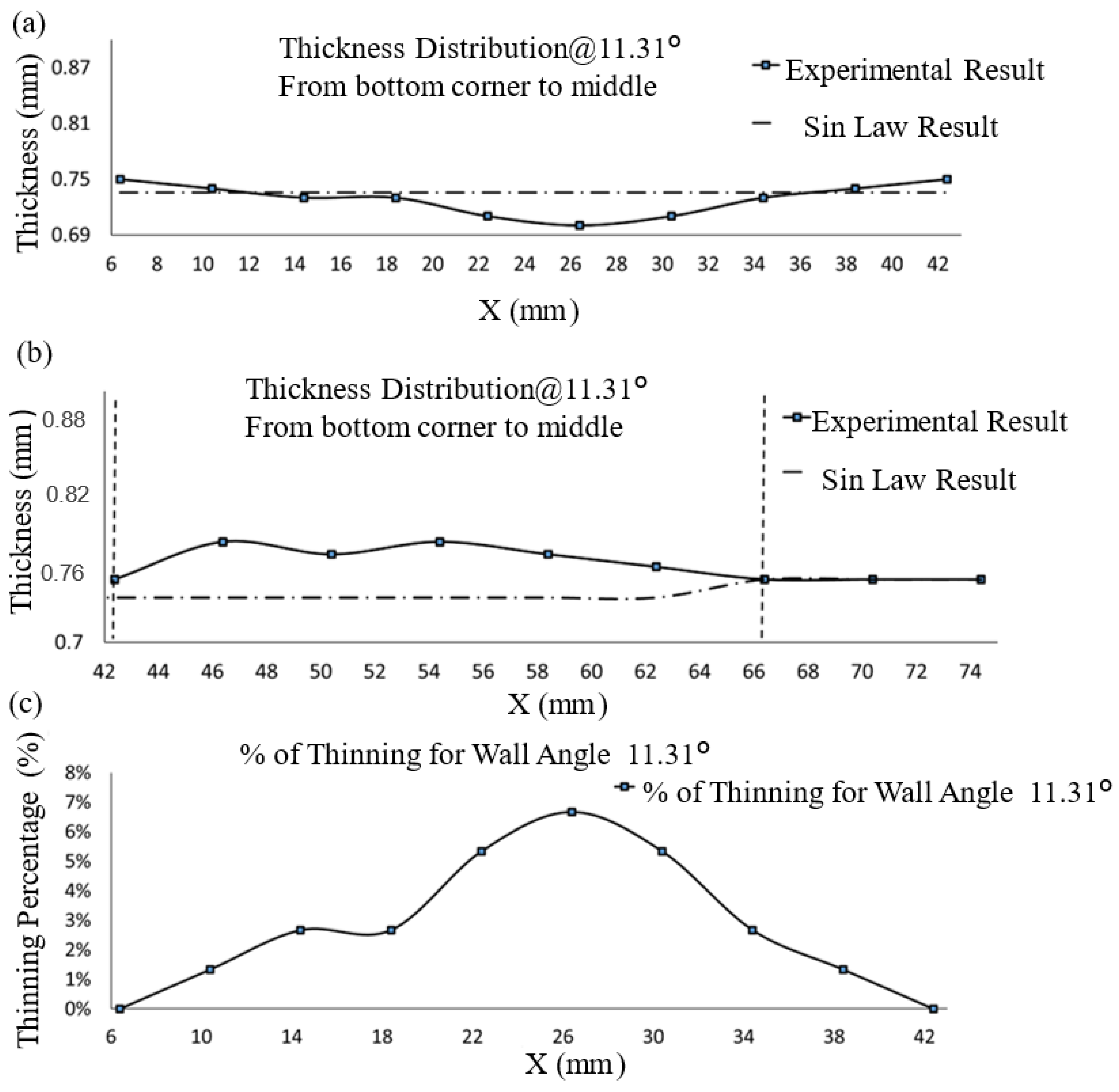
The thickness distributions of both the CAD design and experimental results are depicted in Figure 8, with the data collected from the edge to the center of the workpiece. The thickness was calculated using Equation (1). The values of X, Y, and Z displacements were determined using a coordinate measuring machine (CMM) on both the workpiece bottom and top surfaces. The theoretical thickness distribution was derived through the application of the sine law, as expressed in Equation (2), which was found to be useful in determining the workpiece thickness, according to the study by Cao et al. [37] on the ISF (incremental single forming) process. The measurements were taken at 18 different locations, as shown in Figure 8a.
t = ( x 1 x 2 ) 2 + ( y 1 y 2 ) 2 + ( z 1 z 2 ) 2
where t is the polymeric sheet thickness, x1, y1, and z1 are the top surface route node coordinates, and x2, y2, and z2 are the bottom surface path node coordinates.
The sine law equation, which gives an estimate of the actual thickness of the sheet based on the original thickness, is used to obtain the theoretical thickness distribution, as shown in the following equation:
tf = t0 × Sin((π/2) − (α))
The thickness of the workpiece, represented by tf, can be determined using Equation (2), where t0 represents the workpiece’s initial thickness and α is the wall angle, as illustrated in Figure 8b. The percentage thinning was proportional to the formability of the polymer sheets [38].
Percentage Thinning = (Initial Thickness − Thickness)/Initial Thickness
The equation was introduced by Hussain and Gao [39] in their previous paper, which focused on determining the thickness distribution in SPIF. A similar method was adopted by Lu et al. [40] to calculate the theoretical thickness in double-sided ISF. Tolipov et al. [41] also confirmed the effectiveness of this equation when estimating the thickness distribution during metal forming through their study on multi-point forming.
Sheet thinning is a typical occurrence during incremental forming. The high levels of stress experienced during the process can result in local thinning of the sheet, which can cause an uneven distribution of thickness across the workpiece. This can negatively impact the mechanical properties and appearance of the final product. To mitigate this effect, it is crucial to have an understanding of sheet thinning and be able to predict it during the design and development stages of incremental forming. Predictive models and numerical simulations can be utilized to estimate sheet thinning and optimize the forming process for minimal impact. According to Equation (2), sheet thinning is related to the geometry depth. For a wall angle of 11.31°, the sine law predicted 0.73543 mm of sheet thinning in X along the pyramid wall. The experimental study found an average thickness of 0.745 mm with a thinning rate of 0.6%. The comparison of the measured and theoretical thickness distributions revealed a good agreement, as shown in Figure 9a. The results of the experiment indicated that the thickness of the wall decreases with an increase in forming depth, with a minimum calculated thinning of 0.73543 mm using the sine law equation and 0.7 mm from the experimental measurements.
It is worth noting that in addition to sheet thinning, material buildup is also a phenomenon that can occur during incremental forming; see Figure 9b. The maximum material buildup in the sample was found to be around the pyramid corner of the workpiece. This may be due to the heating and pushing process causing the material to accumulate in the bottom corner of the sheet, resulting in an increase in wall thickness by approximately 3% before returning to its initial thickness, which is also in agreement with SPIF as in [42]. Figure 9c shows how much the workpiece thinned in the new CSPIF when the wall angles were 11.31 degrees. The results showed that 6% was the most thinning that could happen.

3.4. Surface Roughness

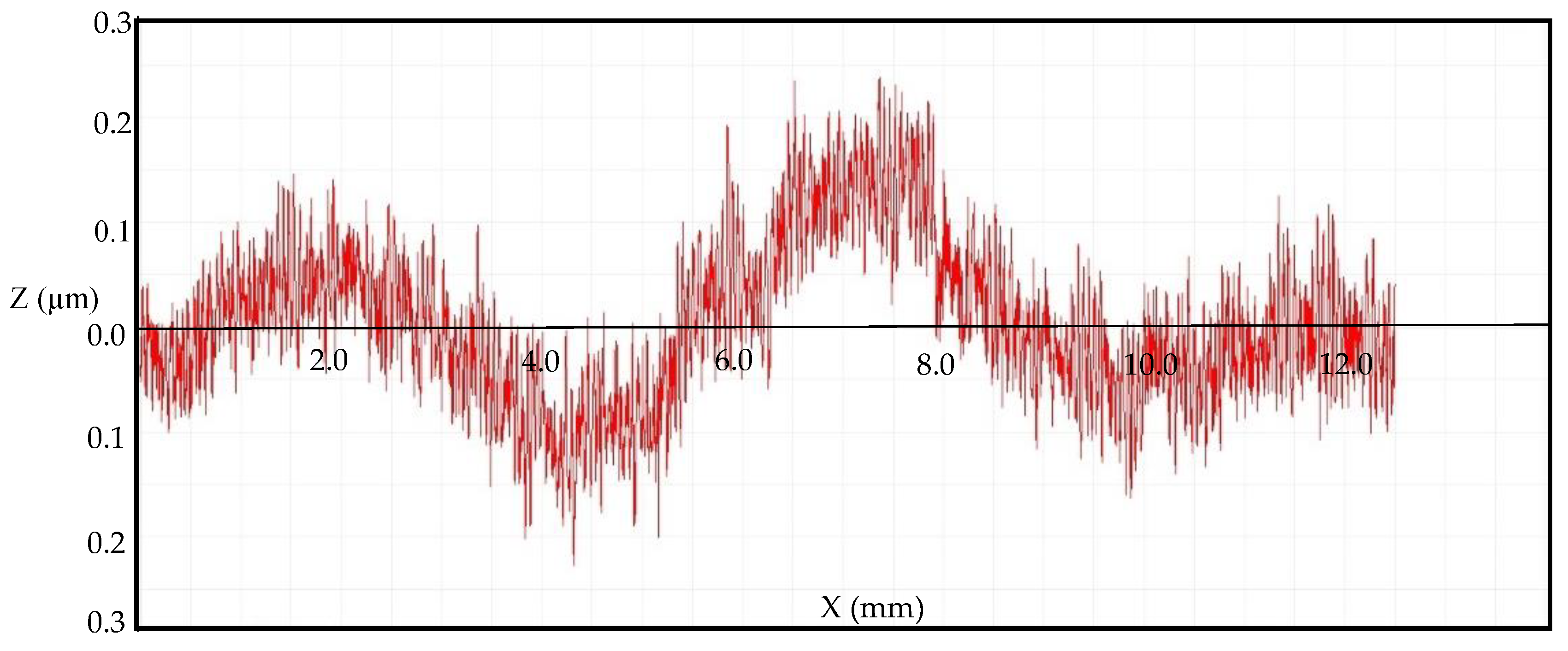
Surface roughness is a critical property for determining the quality of a formed part’s surface. A Mitutoyo Formtracer Avant S-3000 Model Surface Roughness Tester with an accuracy of (0.05 + 0.001 L) µm was used to assess the part’s surface finish. The effect of the hot compressed air on the final part’s quality was also assessed using the surface roughness characterization [43]. In this study, four different roughness parameters were measured: the Average Roughness (Ra) value, which is an internationally recognized parameter for measuring surface roughness and the mean departure of a profile; the root mean square (Rq) value, determined as the square root of the mean squared roughness values over the evaluation length; Rz, calculated as the average of the five highest peaks and five deepest valleys within the evaluation length, offering insights into the height of surface irregularities by accounting for both peaks and valleys; and finally, Rt, which quantifies the total height discrepancy between the highest peak and lowest valley within the evaluation length, providing an assessment of the overall height variation across the surface. All values were measured five times at the same depth and perpendicular to the forming tool movement using a 2.5 mm cut and a 12.5 mm sampling length.
The inner surface of the as-received and experimental workpieces’ surface roughness values are displayed in Table 3 and in Figure 10. The results show surface roughness Ra value increased by 0.3747 mm at the top layer, 0.0514 mm at the middle layer, and 0.1965 mm at the bottom layer when compared with the as-received surface roughness value. The minimum and maximum heights of the roughness profile Rz are obtained in the middle layer (0.5470 mm). At the bottom layer, the difference between the highest peak and the deepest valley is 0.65 mm. Wave format geometry was also noticed in the workspace due to the step size of the nozzle. These wavy surfaces magnify the values of the surface roughness compared to the original values.

4. Conclusions

By eliminating the need for a rigid tool and replacing it with a contactless nozzle, a new design for the CSPIF of polymers has been developed. Five key process parameters were identified, namely air temperature, air pressure, speed of the moving, initial gap, and step-down. The airflow from the compressed air nozzle was found to play a crucial role in the process as it creates a thrust to deform the PC sheet. The thrust force was measured by calculating the value of the air pressure and the affected area on the PC sheet. The precision and accuracy of the deformed workpiece were determined using a coordinate measuring machine (CMM) and were found to have high accuracy with only modest springback and pillow effects. However, deviation from the ideal profile was observed due to the bending effect at the starting point of the nozzle and it was highlighted that proper consideration of fixture design, nozzle placement, and starting position is crucial to minimize deviation. The results also showed that sheet thinning is proportional to pyramid depth and there was good agreement between the measured and theoretical thickness distributions. Material buildup was also observed and was found to be around the pyramid corner of the workpiece. The surface roughness of the samples was also determined and found to have slightly but acceptably increased after the incremental forming due to the step-wise nature of the air nozzle. The study on the new HASPIF configuration opens up a new paradigm in sheet forming. It has shown success in deforming polycarbonate sheets and has the potential to be applied to other polymer materials and potentially metal as well. The results show that this method surpasses traditional SPIF in terms of surface quality and eliminates the need for tools and workpiece defects such as tearing and twisting.

Author Contributions

Conceptualization, K.E., M.A.; methodology K.E., M.A., A.G.; software, H.H., M.A., A.G.; validation, K.E., H.H., M.A., A.G.; formal analysis, K.E., H.H., M.A., A.G.; investigation, M.A., A.G.; resources, K.E.; data curation, K.E.; writing—original draft preparation, H.H., M.A.; writing—review and editing, H.H., M.A.; visualization, K.E., H.H., M.A., A.G.; supervision, K.E.; project administration, K.E. All authors have read and agreed to the published version of the manuscript.

Funding

This research received no external funding.

Data Availability Statement

The data that support the findings of this study are available from the first author, [Mohammad Almadani], upon request.

Conflicts of Interest

The authors of this article declare that they have no conflict of interest regarding the publication of this manuscript.

References

  1. Pratheesh Kumar, S.; Elangovan, S.; Mohanraj, R.; Naveen Anthuvan, R.; Nithin, V. Development of Flexible Mechanism for Two-Point Incremental Forming. In Advances in Forming, Machining and Automation: Select Proceedings of AIMTDR 2021; Springer: Berlin/Heidelberg, Germany, 2022; pp. 37–46. [Google Scholar]
  2. Zhou, C.; Zhang, F.; Wei, B.; Lin, Y.; He, K.; Du, R. Digital twin–based stamping system for incremental bending. Int. J. Adv. Manuf. Technol. 2021, 116, 389–401. [Google Scholar] [CrossRef]
  3. Leszak, E. Apparatus and Process for Incremental Dieless Forming. U.S. Patent No 3,342,051, 19 September 1967. [Google Scholar]
  4. Mohanraj, R.; Elangovan, S. Incremental sheet metal forming of Ti–6Al–4V alloy for aerospace application. Trans. Can. Soc. Mech. Eng. 2019, 44, 56–64. [Google Scholar] [CrossRef]
  5. Li, W.; Attallah, M.M.; Essa, K. Experimental and numerical investigations on the process quality and microstructure during induction heating assisted incremental forming of Ti-6Al-4V sheet. J. Mater. Process. Technol. 2022, 299, 117323. [Google Scholar] [CrossRef]
  6. Pandre, S.; Morchhale, A.; Kotkunde, N.; Kurra, S. Processing of DP590 steel using single point incremental forming for automotive applications. Mater. Manuf. Process. 2021, 36, 1658–1666. [Google Scholar] [CrossRef]
  7. Cheng, Z.; Li, Y.; Xu, C.; Liu, Y.; Ghafoor, S.; Li, F. Incremental sheet forming towards biomedical implants: A review. J. Mater. Res. Technol. 2020, 9, 7225–7251. [Google Scholar] [CrossRef]
  8. Essa, K.; Hartley, P. An assessment of various process strategies for improving precision in single point incremental forming. Int. J. Mater. Form. 2011, 4, 401–412. [Google Scholar] [CrossRef]
  9. Grimm, T.J.; Parvathy, G.V.; Mears, L. Single Point Incremental Forming Springback Reduction Using Edge Stiffener. In Proceedings of the ASME International Mechanical Engineering Congress and Exposition, Virtual, 16–19 November 2020; p. V02AT02A022. [Google Scholar]
  10. Van Viet, M.; Thinh, N.T.; Van Sy, L. Effect of Lubrication on Deforming the Aluminum Sheet with Two Points Incremental Forming Technology. In Proceedings of the 2nd Annual International Conference on Material, Machines and Methods for Sustainable Development (MMMS2020), Nha Trang, Vietnam, 12–15 November 2020; pp. 975–982. [Google Scholar]
  11. Sieczkarek, P.; Wernicke, S.; Gies, S.; Tekkaya, A.; Krebs, E.; Wiederkehr, P.; Biermann, D.; Tillmann, W.; Stangier, D. Wear behavior of tribologically optimized tool surfaces for incremental forming processes. Tribol. Int. 2016, 104, 64–72. [Google Scholar] [CrossRef]
  12. Murugesan, M.; Yu, J.-H.; Jung, K.-S.; Cho, S.-M.; Bhandari, K.S.; Lee, C.-W. Optimization of forming parameters in incremental sheet forming of AA3003-H18 sheets using Taguchi method. Materials 2022, 15, 1458. [Google Scholar] [CrossRef]
  13. Zavala, J.M.D.; Martínez-Romero, O.; Elías-Zúñiga, A.; Gutiérrez, H.M.L.; Vega, A.E.-d.l.; Taha-Tijerina, J. Study of friction and wear effects in aluminum parts manufactured via single point incremental forming process using petroleum and vegetable oil-based lubricants. Materials 2021, 14, 3973. [Google Scholar] [CrossRef]
  14. Li, W.; Essa, K.; Li, S. A novel tool to enhance the lubricant efficiency on induction heat-assisted incremental sheet forming of Ti-6Al-4 V sheets. Int. J. Adv. Manuf. Technol. 2022, 120, 8239–8257. [Google Scholar] [CrossRef]
  15. Li, W.; Shu, C.; Hassan, A.; Attallah, M.M.; Essa, K. Application of machine learning on tool path optimisation and cooling lubricant in induction heating-assisted single point incremental sheet forming of Ti-6Al-4V sheets. Int. J. Adv. Manuf. Technol. 2022, 123, 821–838. [Google Scholar] [CrossRef]
  16. Hassan, M.; Hussain, G.; Wei, H.; Qadeer, A.; AlKahtani, M. Progress on single-point incremental forming of polymers. Int. J. Adv. Manuf. Technol. 2021, 114, 1–26. [Google Scholar] [CrossRef]
  17. Zhu, H.; Ou, H.; Popov, A. Incremental sheet forming of thermoplastics: A review. Int. J. Adv. Manuf. Technol. 2020, 111, 565–587. [Google Scholar] [CrossRef]
  18. Roşca, N.A.; Oleksik, M. Simulation of the Single Point Incremental Forming of Polyamide and Polyethylene Sheets. MATEC Web Conf. 2019, 290, 03014. [Google Scholar] [CrossRef]
  19. Durante, M.; Formisano, A.; Lambiase, F. Formability of polycarbonate sheets in single-point incremental forming. Int. J. Adv. Manuf. Technol. 2019, 102, 2049–2062. [Google Scholar] [CrossRef]
  20. Li, W.; Li, S.; Li, X.; Xu, D.; Shao, Y.; Attallah, M.M.; Essa, K. Crystal plasticity model of induction heating-assisted incremental sheet forming with recrystallisation simulation in cellular automata. Int. J. Adv. Manuf. Technol. 2022, 123, 903–925. [Google Scholar] [CrossRef]
  21. Li, W.; Attallah, M.M.; Essa, K. Heat-assisted incremental sheet forming for high-strength materials—A review. Int. J. Adv. Manuf. Technol. 2023, 124, 2011–2036. [Google Scholar] [CrossRef]
  22. Ambrogio, G.; Gagliardi, F.; Conte, R.; Russo, P. Feasibility analysis of hot incremental sheet forming process on thermoplastics. Int. J. Adv. Manuf. Technol. 2019, 102, 937–947. [Google Scholar] [CrossRef]
  23. Conte, R.; Gagliardi, F.; Ambrogio, G.; Filice, F.; Russo, P. Performance analysis of the incremental sheet forming on PMMA using a combined chemical and mechanical approach. In Proceedings of the AIP Conference Proceedings, Dublin, Ireland, 26–28 April 2017. [Google Scholar]
  24. Okada, M.; Kato, T.; Otsu, M.; Tanaka, H.; Miura, T. Development of optical-heating-assisted incremental forming method for carbon fiber reinforced thermoplastic sheet—Forming characteristics in simple spot-forming and two-dimensional sheet-fed forming. J. Mater. Process. Technol. 2018, 256, 145–153. [Google Scholar] [CrossRef]
  25. Sridhar, R.; Rajenthirakumar, D. Polymer sheet hot incremental forming-an innovative polymer forming approach. Polym. Polym. Compos. 2016, 24, 447–454. [Google Scholar] [CrossRef]
  26. Al-Ghamdi, K.A. Spring back analysis in incremental forming of polypropylene sheet: An experimental study. J. Mech. Sci. Technol. 2018, 32, 4859–4869. [Google Scholar] [CrossRef]
  27. Bagudanch, I.; Lozano-Sánchez, L.M.; Puigpinós, L.; Sabater, M.; Elizalde, L.E.; Elías-Zúñiga, A.; Garcia-Romeu, M.L. Manufacturing of polymeric biocompatible cranial geometry by single point incremental forming. Procedia Eng. 2015, 132, 267–273. [Google Scholar] [CrossRef]
  28. Sabater, M.; Garcia-Romeu, M.L.; Vives-Mestres, M.; Ferrer, I.; Bagudanch, I. Process parameter effects on biocompatible thermoplastic sheets produced by incremental forming. Materials 2018, 11, 1377. [Google Scholar] [CrossRef] [PubMed]
  29. Thangavel, K.; Duraiswamy, R.; Nagarajan, S.; Ramasamy, S. Influence of roller ball tool in single point incremental forming of polymers. Teh. Vjesn. 2019, 26, 171–176. [Google Scholar]
  30. Medina-Sánchez, G.; Torres-Jimenez, E.; Lopez-Garcia, R.; Dorado-Vicente, R.; Cazalla-Moral, R. Temperature influence on single point incremental forming of PVC parts. Procedia Manuf. 2017, 13, 335–342. [Google Scholar] [CrossRef]
  31. Miroir, M.; Laniel, R.; Brient, A.; Kerbrat, O. Water jet incremental sheet metal forming: A critical state-of-the-art review and a proposal for technological windows. Int. J. Adv. Manuf. Technol. 2022, 119, 4159–4175. [Google Scholar] [CrossRef]
  32. Richeton, J.; Ahzi, S.; Vecchio, K.S.; Jiang, F.C.; Adharapurapu, R.R. Influence of temperature and strain rate on the mechanical behavior of three amorphous polymers: Characterization and modeling of the compressive yield stress. Int. J. Solids Struct. 2006, 43, 2318–2335. [Google Scholar] [CrossRef]
  33. Dar, U.A.; Zhang, W.; Xu, Y.; Wang, J. Thermal and strain rate sensitive compressive behavior of polycarbonate polymer-experimental and constitutive analysis. J. Polym. Res. 2014, 21, 519. [Google Scholar] [CrossRef]
  34. Kaessinger, J.C.; Kors, K.C.; Lum, J.S.; Dillon, H.E.; Mayer, S.K. Utilizing Schlieren imaging to visualize heat transfer studies. In Proceedings of the ASME International Mechanical Engineering Congress and Exposition, Montreal, QC, Canada, 14–20 November 2014; p. V005T005A033. [Google Scholar]
  35. Borboni, A.; De Santis, D. Large deflection of a non-linear, elastic, asymmetric Ludwick cantilever beam subjected to horizontal force, vertical force and bending torque at the free end. Meccanica 2014, 49, 1327–1336. [Google Scholar] [CrossRef]
  36. Archansdran, S.; Shaari, M.; Rosly, M. Characterization of double layer IPMC bending actuation. ARPN J. Eng. Appl. Sci. 2016, 11, 6536. [Google Scholar]
  37. Cao, T.; Lu, B.; Xu, D.; Zhang, H.; Chen, J.; Long, H.; Cao, J. An efficient method for thickness prediction in multi-pass incremental sheet forming. Int. J. Adv. Manuf. Technol. 2015, 77, 469–483. [Google Scholar] [CrossRef]
  38. Limpadapun, K.; Kesvarakul, R. An investigation of thickness distribution in Single-Point incremental forming with different forming parameter in Hot-dipped zinc-coated cold-rolled steel. Mater. Today Proc. 2020, 33, 1988–1992. [Google Scholar] [CrossRef]
  39. Hussain, G.; Gao, L. A novel method to test the thinning limits of sheet metals in negative incremental forming. Int. J. Mach. Tools Manuf. 2007, 47, 419–435. [Google Scholar] [CrossRef]
  40. Lu, B.; Fang, Y.; Xu, D.K.; Chen, J.; Ai, S.; Long, H.; Ou, H.; Cao, J. Investigation of material deformation mechanism in double side incremental sheet forming. Int. J. Mach. Tools Manuf. 2015, 93, 37–48. [Google Scholar] [CrossRef]
  41. Tolipov, A.; Elghawail, A.; Abosaf, M.; Pham, D.; Hassanin, H.; Essa, K. Multipoint forming using mesh-type elastic cushion: Modelling and experimentation. Int. J. Adv. Manuf. Technol. 2019, 103, 2079–2090. [Google Scholar] [CrossRef]
  42. Abe, Y.; Mori, K.-i.; Ito, T. Plate forging of drawn cup with flange including thickening of corners. Manuf. Rev. 2014, 1, 16. [Google Scholar] [CrossRef]
  43. Abd Ali, R.; Chen, W.; Al-Furjan, M.; Jin, X.; Wang, Z. Experimental investigation and optimal prediction of maximum forming angle and surface roughness of an Al/SUS bimetal sheet in an incremental forming process using machine learning. Materials 2019, 12, 4150. [Google Scholar] [CrossRef]
Figure 1. (a) A schematic diagram of CSIPF, (b) The experimental setup, (c) The air nozzle in operation. Video: https://www.dropbox.com/s/w0n4n3narl0dgvi/Contact-less%20SPIF.mp4?dl=0 (accessed on:1 September 2023).
Jmmp 07 00179 g001
Figure 2. (a) CAD design of the nozzle, (b) 3D-printed steel nozzle.
Jmmp 07 00179 g002
Figure 3. Truncated pyramid path trajectory (a) Full path, (b) Path movement.
Jmmp 07 00179 g003
Figure 4. The Schlieren setup.
Jmmp 07 00179 g004
Figure 5. Airflow using (a) thermal camera, (b) the Schlieren method.
Jmmp 07 00179 g005
Figure 6. Comparison between CAD drawing and deformed PC workpiece using CIPF technique. (a) Deflection at the base of the shape (b) Deflection near the center of the shape.
Jmmp 07 00179 g006
Figure 7. Temperature tail at the (a) First path and (b) Last path with tail overlapping. S, H, and C represent surrounding, hot and cold spots, respectively.
Jmmp 07 00179 g007
Figure 8. (a) Experimental thickness distribution between the top and bottom surfaces, (b) Schematic diagram of sine law.
Jmmp 07 00179 g008
Figure 9. Thickness distribution using the experimental and theoretical calculations showing (a) sheet thinning, (b) materials building up, and (c) thinning percentage.
Jmmp 07 00179 g009
Figure 10. A sample of the surface roughness topography.
Jmmp 07 00179 g010
Table 1. Properties of Lexan® 9030 polycarbonate (PC) [32,33].
Thickness0.75 (mm)
Density1.2 (g/cm)
Young’s modulus2.3 (Gpa)
Yield stress60 (Mpa)
Poisson’s ratio0.38
Maximum elongation110%
Thermal conductivity0.2 (W/m.°C)
Table 2. Process parameters.
Air pressure 1 (bar)
Air temperature 160 (°C)
Nozzle speed 750 (mm/min)
Initial gap6 (mm)
Step-down mm)
Table 3. Surface roughness values.
Sample NoRa (µm)Rq (µm)Rz (µm)Rt (µm)
As-received 0.07960.08460.19380.2441
Experimental (top)0.45430.47220.55081.5403
Experimental (middle)0.13100.14900.54701.5228
Experimental (bottom)0.27610.30670.65211.3956
Average0.28710.30930.58331.486
Disclaimer/Publisher’s Note: The statements, opinions and data contained in all publications are solely those of the individual author(s) and contributor(s) and not of MDPI and/or the editor(s). MDPI and/or the editor(s) disclaim responsibility for any injury to people or property resulting from any ideas, methods, instructions or products referred to in the content.