Article

Effect of Infill Pattern on Impact Toughness, Microstructure, and Surface Roughness of Inconel 625 Built via Filament-Based Material Extrusion Additive Manufacturing

Department of Mechanical Engineering, Universitas Indonesia, Kampus UI, Depok 16424, Indonesia
*
Author to whom correspondence should be addressed.
J. Manuf. Mater. Process. 2023, 7(3), 114; https://doi.org/10.3390/jmmp7030114
Submission received: 4 May 2023 / Revised: 7 June 2023 / Accepted: 8 June 2023 / Published: 11 June 2023

Abstract

:
Filament-based material extrusion additive manufacturing (FMEAM) is an additive manufacturing technique that uses 3D printing. Additive manufacturing could build parts with infill variations. Solid or triangular infill pattern could be selected as needed. The solid pattern will have the maximum material volume, while the triangular pattern will contain a triangular lattice structure that fills the voids in the volume so the material requirement is reduced. This is valuable in optimizing the requirements of metallic materials for mechanical properties without changing the surface shape. The alloy Inconel 625, which is very popular in the aerospace industry have been developed as a feed material of FMEAM. However, for developing rotating parts, such as turbine blades, impact toughness, surface roughness and microstructure need to be investigated. This research was conducted to determine the effect of the infill pattern on the impact toughness, morphology of surface fracture, microstructure of side surface and surface roughness with Inconel 625 material built using FMEAM. The Charpy impact test, s ASTM 23, with v-notch testing method and SEM with EDS were performed. The results showed that the impact toughness for solids was higher than the value for the triangular infill pattern. It was discovered that the cavities in the triangular lattice structure within the specimen reduced the impact toughness to 57.6%. Micropores and residual polymer trapped on the surface reduce impact toughness. However, the same surface shape on solid and triangular infill patterns with surface roughness of 2.44 and 10.03 µm is still feasible for manufacture.

1. Introduction

Additive manufacturing (AM) is defined in ASTM52900-21 as the process of joining materials to make parts from 3D model data, usually layer upon layer, as opposed to subtractive manufacturing and formative manufacturing methodologies [1,2,3,4]. It can be used to design and develop complex shapes, hierarchies, materials, and functions as well as to build without planning, tooling, and fixturing [5,6,7,8]. It has been reported that Selective Laser Sintering (SLS) [9,10,11,12], Direct Metal Deposition (DMD) [13,14,15], Electron Beam Melting [16], and Plasma Deposition Manufacturing [17] are the methods commonly applied using metallic materials. The methods usually require high manufacturing costs with relatively high machine prices [18]. However, additive manufacturing conducted using the filament method has been discovered to require cheaper equipment, low manufacturing costs, simple mechanisms, and is considered as an easy method of operations using different materials including metallic ones compared to the other methods [8,19]. There is also the need to consider reduced costs, fabrication time, and material volume, thereby leading to the implementation of the filling method with a lattice structure [20]. This method has been discovered to be good for both solid and porous or lattice structures. It also has functions in additive manufacturing of non-solid products with due consideration for the reduction in the structural parts with shock loads, such as automotive components, aerospace, or other machine elements in addition to its function in prototyping [20,21]. Moreover, the determination of the additive manufacturing properties in a solid and non-solid infill is important to manufacturing engineering.
Material extrusion additive manufacturing (MEAM) with metal filaments involves mixing metal powder particles with polymer binders to produce a filament which can be used continuously as feed in a 3D printer to print layer by layer until it is finished. This process is usually followed by a chemical and temperature treatment in a heating furnace where the polymer is removed from the part and powder particles coalesce [22]. It is pertinent to note that the metallic filament-based material extrusion process requires filaments containing an optimal mix of metal powder and bonding systems. Meanwhile, Atomic Diffusion Additive Manufacturing (ADAM) is a recent layer-wise process patented by Markforged for metals filament-based material extrusion. It can be classified as an indirect additive manufacturing process which involves encasing the filament of metal powder in a polymer binder [23] applied to support the part during the printing process. The binder is usually removed through a debinding process using solvent and a thermal process after printing. The next process is sintering which involves heating the part to a temperature of the metal powder undergoing diffusion in order to ensure it experiences compaction and shrinkage. This means several challenges are associated with metal filament-based material extrusion technology starting from the production of the metal filaments to CAD or CAM, printing, and post-printing processes [24].
Process parameters, such as the infill pattern, are usually selected according to the need to save materials and the purpose of the printing process. This is due to their influence on the printing results, specifically the mechanical properties. Meanwhile, there is no problem in applying a non-solid infill pattern to needs, such as prototyping. It is also important to note that the printer in the Eiger software has three infill pattern options normally selected in the pre-processing stage and these include the solid, triangular, and gyroid patterns. Moreover, there is a need to plan by adjusting the roof, floor, and wall layers of the model to be printed in order to improve the mechanical properties of the surface. The infill pattern, wall and floor layers, as well as roof sections associated with the application of the infill-layer method of part built are presented in Figure 1. The number of walls was observed to range from two to eight layers while the floor and roof are between four to sixteen layers, with the height set at a default value of 0.125 mm. Furthermore, the trajectory of the extrusion nozzle on the solid infill pattern was discovered to be at an angle of 45° on the first layer, increased to 135° on the second, back to 45° on the third layer, and the values alternate continuously on each layer. It is pertinent to note that the Eiger software does not have the capacity to predict or estimate the effect of these layers’ thickness on the mechanical properties of the part. This was observed from the investigation conducted by Henry et al. [25] to determine the influence of printing orientations on the tension, shear, and bending response of 17-4 PH stainless steel processed via ADAM. The results showed that the layer orientation of different parts led to a loss of 10–15% in the strength of the part and the UTS due to a 20% weight reduction in the infill density [26]. Galati et al. [23] also conducted a preliminary study on the densities and surface roughness of parts by varying the layer thickness of printed 17-4 PH material and the dimensional accuracy of the parts was found to be rather good based on the application of ADAM.
The impact test associated with the metal part of MEAM is very useful to understand the fracture mechanics of metal filament-based material extrusion technology. This is due to its ability to measure the amount of energy absorbed by a material during high strain rate conditions before failure. Several studies applied this test to Inconel 625 material as indicated in Puppala et al. [27] evaluation of the fracture and impact toughness using laser metal deposited and the stress-relieving heat treatment was observed to have increased the impact energy from 48–50 J to 50–54 J. Another study also showed that the impact toughness of the material’s base metal is approximately 72 J [28], while the laser rapid manufacturing (LRM) was estimated at 194–254 kJ/m2 [27], and laser metal deposited was approximated at 137 J with horizontal build orientation and non-heat treatment [29]. In terms of orientation, Yan et al. [30] examined the effect of selective laser melting of Inconel 625 material on the building directions associated with the microstructure, surface roughness, and pulsed microplasma [31]. Another study also determined the microstructure and hardness using a laser-based process [32]. Moreover, filament-based research has been conducted with a focus on the effect of orientation on the impact strength of polymeric materials [33,34]. There is no manuscript that reviews the mechanical properties of impact toughness studied using metal filaments of MEAM with high temperature resistant and corrosion resistant materials, such as Inconel. The novelty of the impact toughness properties are manufactured with filament-based MEAM.
Inconel 625 material is a strong nickel chromium-based superalloy which is highly resistant to corrosion at elevated temperatures. It is also easy to print, thereby making it applicable in building functional prototypes and final products designed for harsh environments. The material is widely used in the aerospace, automotive, and energy industries due to its outstanding high-temperature performance under static load, fatigue, and elongation as well as its application at temperatures as high as 980 °C [35]. It has also been used in additive manufacturing but most of the previous studies focused on laser-based processes [36]. This means there is a need to study the impact toughness for filament-based material extrusion additive manufacturing conducted using Inconel 625 filament materials to serve as a dataset to drive product design decisions, such as turbine blades, and guide future research on the fracture behavior of materials through this process.
This research was conducted to determine the effect of the infill pattern on impact toughness and surface roughness of metal parts manufactured via the MEAM using Inconel 625 filament material. The morphology of surface fracture and the microstructure of the side surface were also investigated. The results are expected to provide important information related to manufacturing engineering with Inconel 625 material manufactured by the MEAM.

2. Materials and Methods

The specimens were manufactured using a 3D Printer with Atomic Diffusion Additive Manufacturing (ADAM). It was observed that the 3D Printer have maximum manufacturing capabilities of up to 250 × 183 × 150 mm3 from a build volume of 300 × 220 × 180 mm3, with the ability to carry a maximum load of just 10 kg from the build platform [23]. Moreover, the temperature of the build chamber during the printing process was 48 °C, the build platform had a temperature of 112 °C, and the extrusion nozzle’s temperature was 220 °C. The sheets placed at the top of the build platform were vacuum sealed at 45.94 kPa to facilitate adhesion during manufacturing and smooth removal at the end of the process. The printer nozzle extruded metal filament to build the part layer by layer and the result was eventually called the printed “green” parts followed by a washing process using Wash-1. The green parts were subsequently placed in a basket and lowered into an immersion chamber. Furthermore, the Opteon SF-79 solvent was heated in the boiling chamber, cooled using condensing coils to ensure a recapture in a water separator, and returned to the immersion chamber. After a prescribed length of time, the chemically de-bound part was removed, air-dried, and weighed to obtain a mass loss of 3.8%. This was the amount of wax binder dissolved using the solvent, and then the de-bound (“brown”) part was made ready to be sintered in the Sinter-1 furnace.
The next process involved placing the brown part into the Sinter-1 Furnace for thermal debinding and sintering. The furnace has a cylindrical volume with a diameter of 141 mm and a length of 305 mm. It has the ability to attain a temperature up to 1300 °C depending on the materials used and also works in an inert atmosphere using Argon [23]. The system works automatically according to the material selected by the operator. When the operator selects the material to be sintered, the system will work automatically from start to finish and then the part is ready to be pulled out. There is no information about the temperature of Sinter-1 during operation.
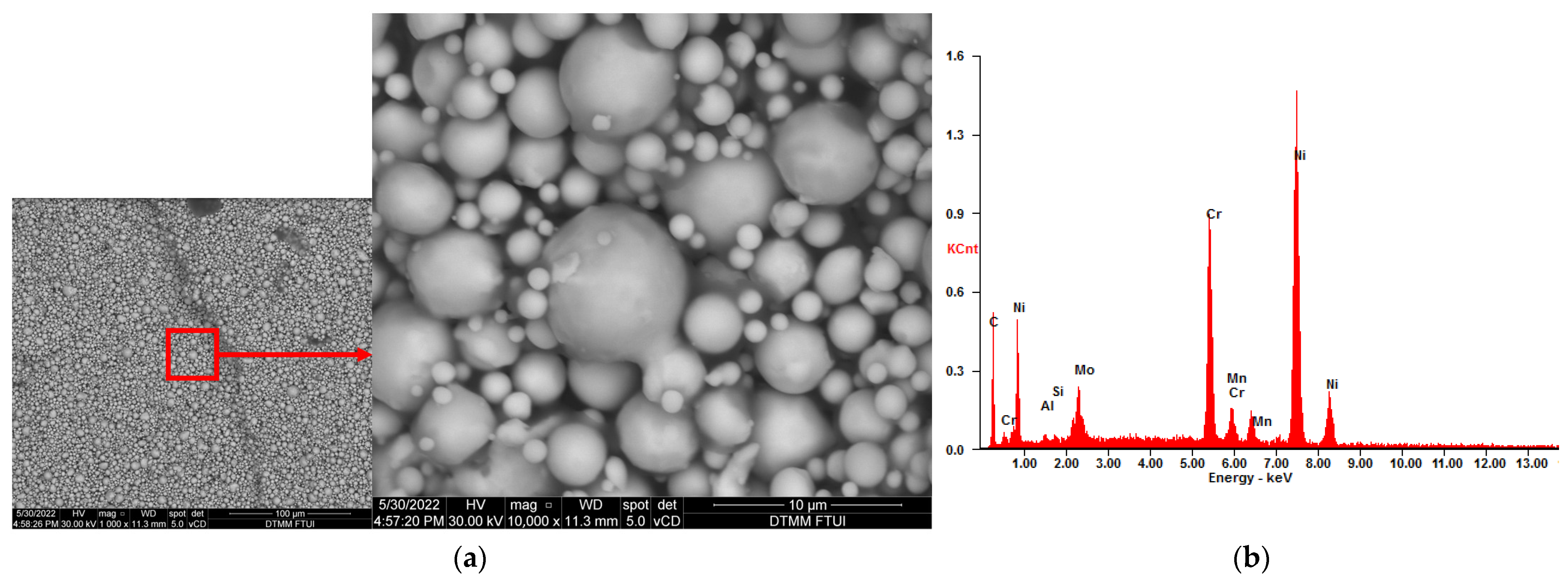
The scanning electron microscopy (SEM) image and EDS analysis performed via FEI INSPECT F50 from section area of the filament Inconel 625 contain Inconel powder and polymer at a high voltage of 30 kV, magnification of 1000× and 10,000×, SE images, spot size 5, and work distance of 11.3, as shown in Figure 2a. The SEM image shows large and small granules from the filament bonds of the material. It was observed to contain several atom elements dominated by Nickel, Chromium, and Carbon as shown in Figure 2b and Table 1. Figure 2b shows the EDS spectrum of Inconel 625 filaments. Nickel has the highest content followed by Chromium, Carbon, Molybdenum, Manganese, Aluminum, and Silicon. However, the percentage of Ni atoms was observed to be lesser than those of C because they have a larger size. This value is obtained from the surface scanned area so it does not describe the entire composition. The rest of the composition is polymer binder that are bound together with the metal powder to produce the metal filament. The polymer binder acts as a temporary support material during the printing process and is later removed through debinding.
According to Table 1, the composition of Inconel 625 filament by weight (wt%) contains 45.7% Nickel, 16.9% Chromium, 7.0% Molybdenum, and 28.0% Carbon. Usually Inconel 625 contains 58.0% min of Nickel, 20.0–23.0% Chromium, 8.0–10.0% Molybdenum, and 0.1% max of Carbon by percent weight [37]. As seen, scanning of SEM in certain areas affects the weight percentage. The material being scanned is a filament consisting of Inconel powder and polymer, causing a higher carbon value in the weight percentage and lowering the percentage of Inconel alloy. This analysis did not describe the phase of the polymer contained in the filament.
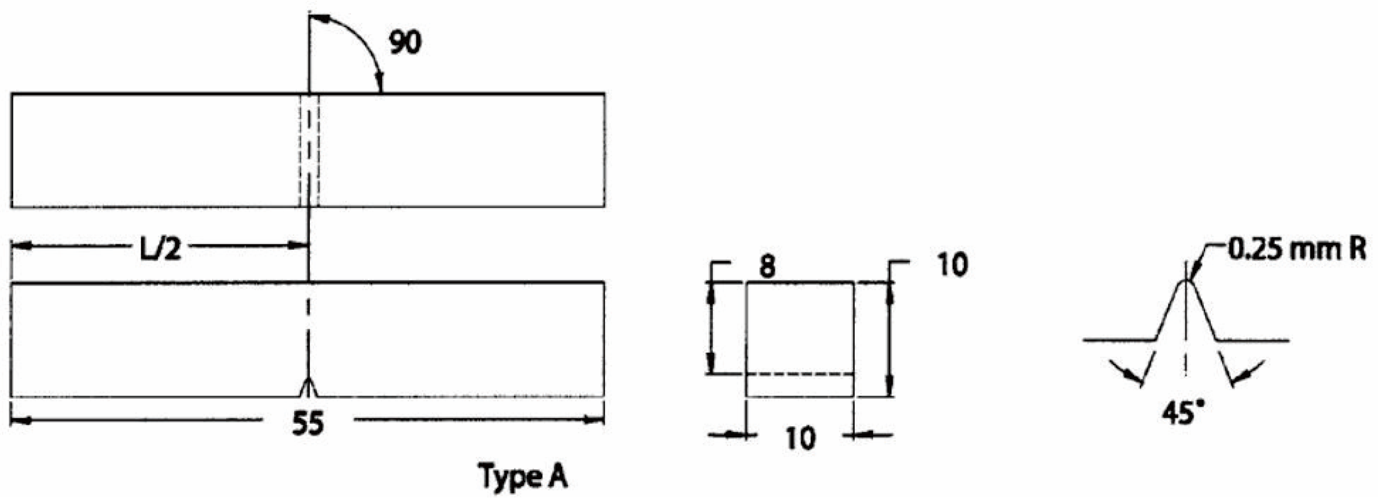
The impact test specimens manufactured via the MEAM were based on ASTM 23 with v-notch testing method [34,38,39] with the dimensions presented in t Figure 3. The manufactured specimens built with Inconel 625 were prepared via Metal-X Printer of Markforged in i-CEL Lab FTUI. There are two variations of infill pattern, namely the solid and the triangular infill pattern, manufactured via MEAM.
The first step in pre-processing of filament-based material extrusion is to design a 3D model. This research applied Software Inventor for this purpose and the result was saved in an STL format. Eiger software was also used to set up the filament-based material extrusion additive manufacturing with the model uploaded through the online systems and different models of infill patterns, including the solid and triangular used as parameters. Moreover, Inconel 625 was selected as the material and no raft was provided during the manufacturing process because the surface of the specimen was flat. The roof, floor, and wall parameters were also selected based on the four layers having a default height of 0.125 mm. The design parameters entered to generate results from the Eiger software are presented in Table 2.
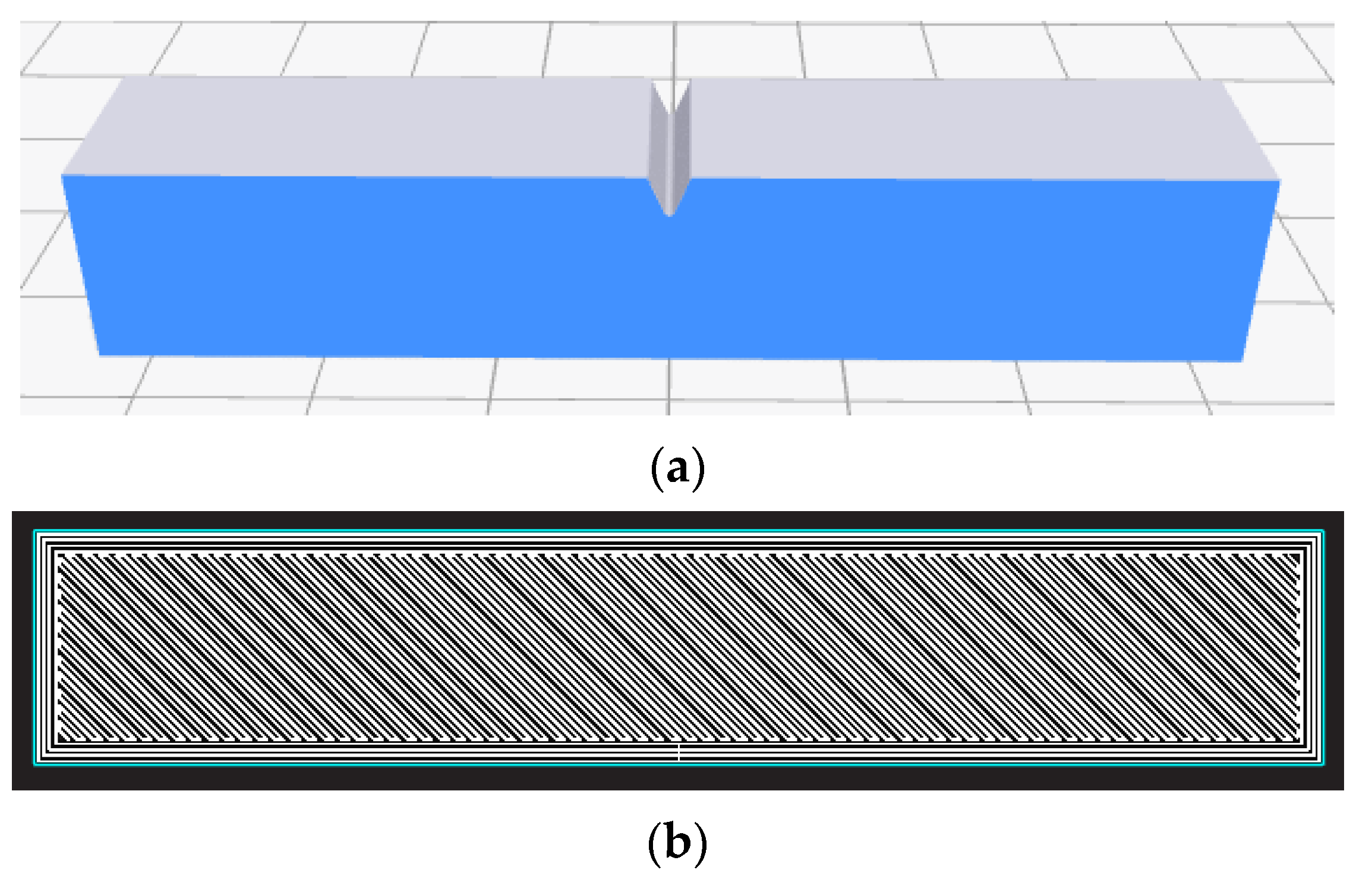
Figure 4a shows a three-dimensional view of an ASTM E23 specimen oriented on the build platform of the printer. The model used for the test was produced with two different infill patterns, including the solid in Figure 4b and the triangular in Figure 4c, each of which was replicated in three specimens. The trajectory pattern was also automatically generated via Eiger software and the direction for the solid infill was discovered to be at an angle of 45° on the first layer, increased to 135° on the second, returned to 45° on the third layer, and the values alternate continuously on each layer, as shown in Figure 1. Meanwhile, the trajectory for the triangular infill was drawn in the form of a regular pattern of triangles. It is also important to note that the wall, floor, and roof layers were also generated automatically using the software.
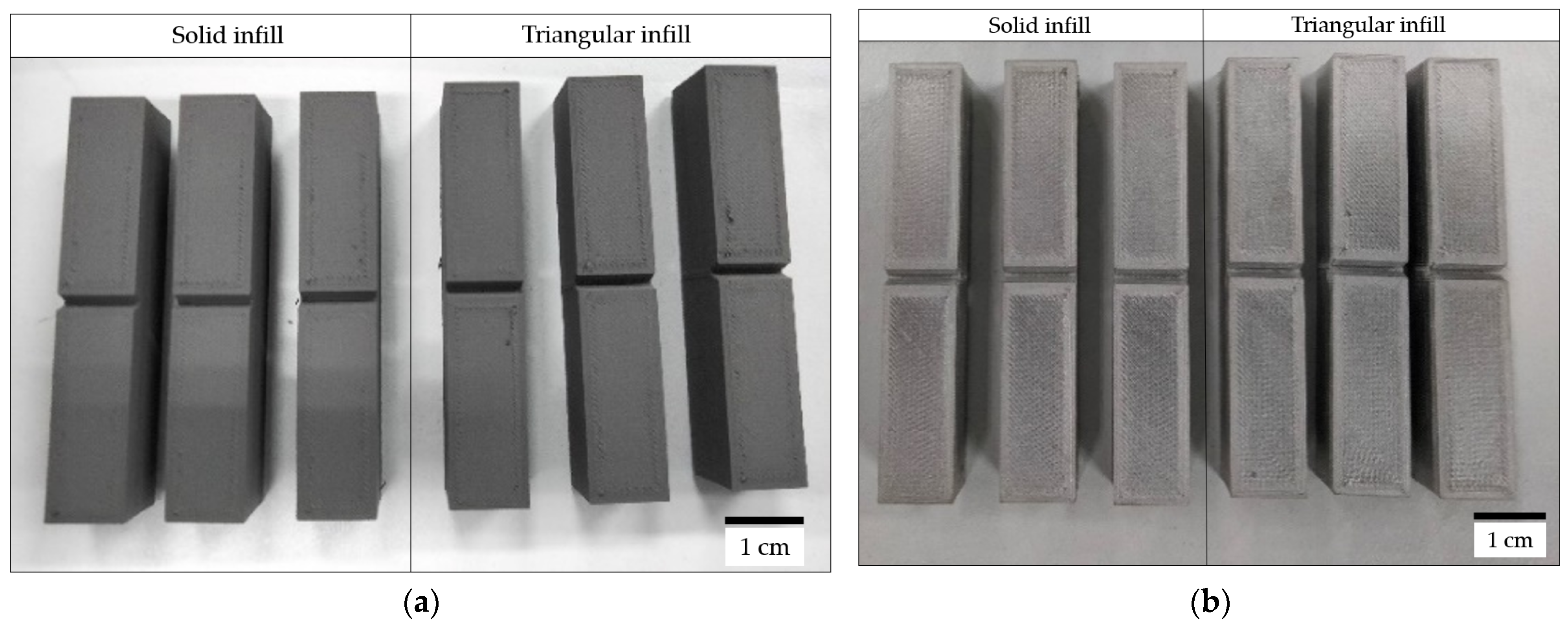
The filament-based material extrusion specimens produced from the Metal X Printer are shown in Figure 5, with the printed part presented in Figure 5a while the sintered part is in Figure 5b. It is important to reiterate that the printed part was immersed in the Opteon-79 liquid in Wash-1 for 20 h to remove the wax binder and later dried in the chamber for 6 h to obtain a mass loss of 3.8%. This was followed by the placement of the part into Sinter-1 for the sintering process which was conducted automatically using the parameters set by the system. The operator was only required to select the Inconel 625 material in the options displayed and open the Argon gas pipe valve to allow gas flow into the Sinter-1. The process was conducted for approximately 28 h automatically to ensure thermal debinding, sintering, and cooling. After the process concluded, the part was then removed from Sinter-1 and analyzed.
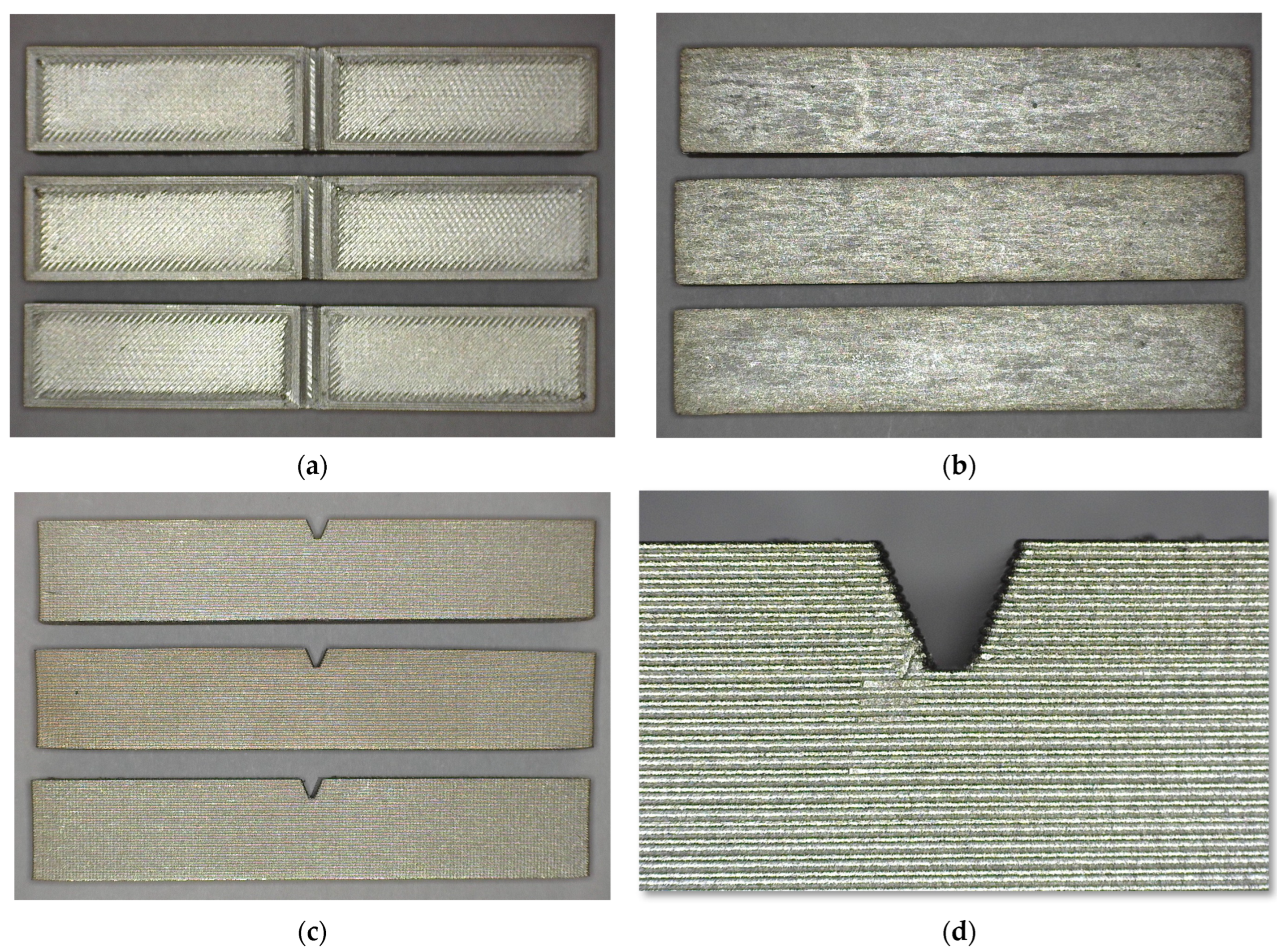
These sintered parts are impact specimens that is already in metal shape are shown in Figure 6. Figure 6a–c are surface view of top, bottom, and side of sintered parts. On top view, wall layer and roof layer are clearly seen on the surface, the boundaries of the two are clearly visible. The bottom view, wall layer boundaries are not visible, appear uniform on the surface. On side view is surface of layered with uniform layer thickness from bottom to top. Whereas Figure 6d is the side surface of the notch section which looks more clearly built up layer by layer.
Procedure of impact was assessed via ASTM 23 with v-notch testing method [34,38,39]. The solid and triangular infill patterns, each with three specimens was tested using the Charpy Impact Tester 50 kg M GT-7052-50 at room temperature. The impact toughness results was recorded and analysis statistically to get the average data of every pattern. The fracture cross-section of the impact specimen was analyzed using a Dino-Lite Digital Microscope. Fractography analysis of morphologies of fracture surfaces and microstructure analysis of side surface were performed via SEM of Quanta 650 at a high voltage of 20 kV. Samples were analyzed directly without polish. The surface roughness was also investigated on the top, side, and bottom of the sintered part of the specimens using a Surfcom 2900SD3 and the results for each surface were recorded as the Ra data.

3. Results and Discussion

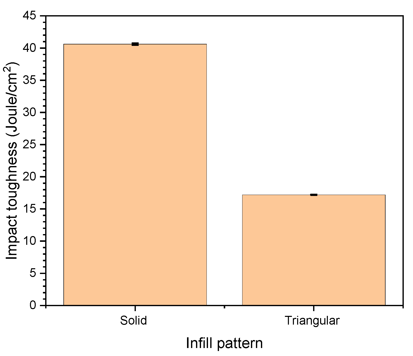
The impact toughness value for the Inconel 625 material are presented in Figure 7, showed that the solid infill pattern had 40.61 Joule/cm2 while the triangular infill pattern had 17.20 Joule/cm2. The thin lattice structure with large cavities in the triangular infill pattern was observed to have caused a 57.6% reduction in the impact toughness compared to the solid infill pattern due to a decrease in its ability to absorb energy. This is in line with the definition of impact toughness as the ability of the material to absorb energy from the impact load. It has also been reported in previous studies that the value of filament-based material extrusion is usually smaller compared to laser-based additive manufacturing [27,28,29].
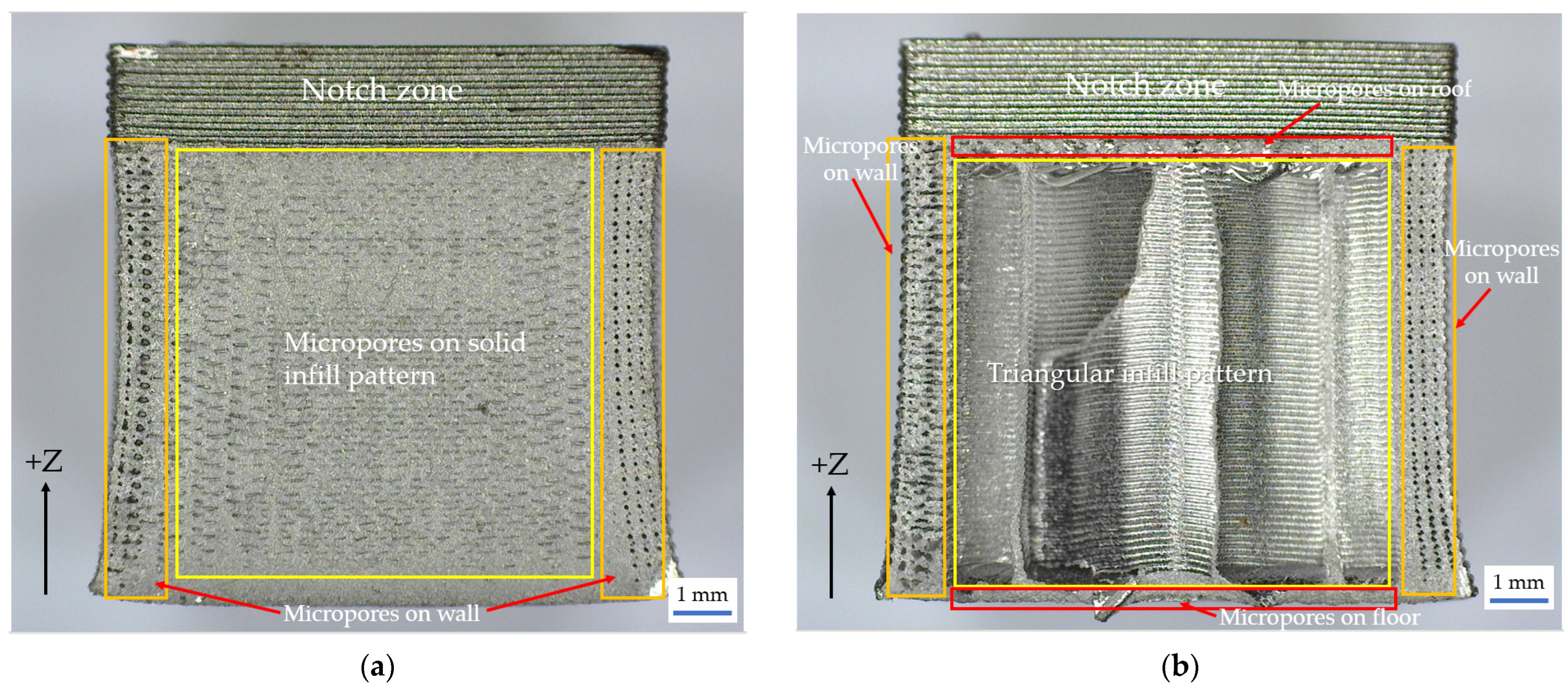
Figure 8 shows the fracture surface of impact test of Inconel 625 material built via filament-based material extrusion. This figure was captured using the Dino-Lite Digital Microscope with 25× magnification. Figure 8a shows the fracture surface of the solid infill pattern specimen and a thin wall was observed in the four layers on the left and right. It can also be seen that the solid infill pattern is in the middle of the fracture surface. Meanwhile, Figure 8b indicates the fractured surface of the triangular infill pattern in the walls, roofs, and floors, each with four layers. It is important to note that there are micropores for all the infill patterns. They were observed at the distance between the hatches on the wall with a uniform pattern. The micropores were also present in the solid pattern as indicated in the cleavage fracture caused by the pattern used in filling the solid section with the extrusion nozzle trajectory forming an angle of 45°, as shown in Figure 1. The micropores were believed to have been caused by the content of the filament binder material lost during the debinding process through immersion in a liquid solvent and burned in the sintering process, thereby leading to a shrinkage in the product. It was discovered from a previous study [40] that the yield data provided for 316 L stainless steel experienced a width shrinkage of 16.3%, height shrinkage of 17.4%, and the final part density was 95% of the original. The Inconel 625 material applied in ADAM technology also showed 16.92% length shrinkage, 16.67% width shrinkage, 15.96% overall shrinkage, and the final part density was 8.25 g/cm3, which is 97.74% of the 8.44 g/cm3 recorded for the Inconel 625 base metal [37]. This means that the results of the additive produced were close to perfect.
The SEM micrographs of the morphologies of fracture surface is presented in Figure 9 and Figure 10. Figure 9 is a fractography analysis of the morphologies of fracture surfaces for solid pattern at a magnification of 100× and 1000×, mixing BSE and SE images, spot size 2.5, and work distance of 8.1 and 8.2, respectively. The figure shows the cleavage fracture with river pattern in the solid faults and the uneven grain size was found to look like a cellular structure. It is pertinent to note that the non-uniform grain has the ability to reduce the mechanical properties [28,41]. A previous study also showed that the mechanical properties of material extrusion additive manufacturing were lower compared to laser-based processes [8]. Moreover, there are micropores, impurities, and remnants of polymer unburn during sintering, which affect the mechanical properties of Inconel 625. The presence of visible micropores in the specimen reduced its ability to withstand impact loads because micropores can cause crack initiation and growth up to the stage of the final collapse from the notch zone.
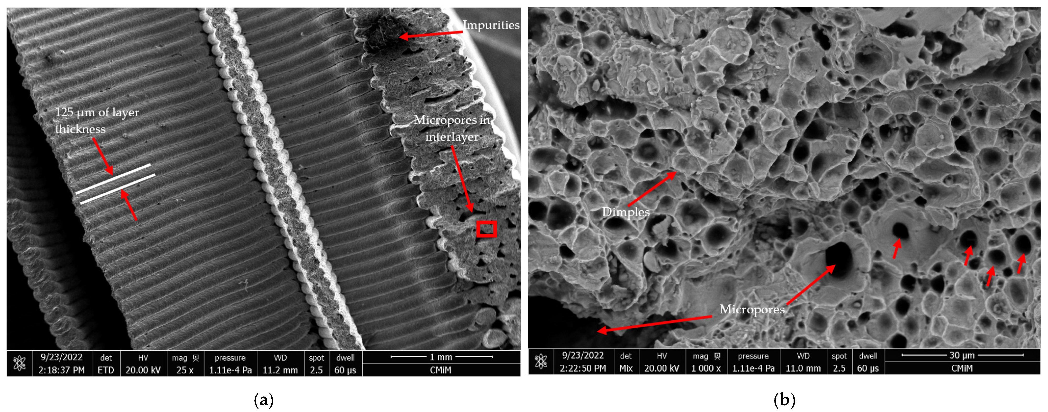
The morphology of fracture surface of the triangular infill pattern specimen is shown in Figure 10. The SEM micrographs are that of at 25× magnification of SE images and 1000× magnification of mixed images, spot size of 2.5 and work distance of 11.0 and 11.2, respectively. It was discovered that this infill pattern also has micropores on the surface of the fracture. The layer thickness was found to be 0.125 mm and the walls of the triangular lattice structure were thin with only one layer. Moreover, the cellular lattice walls were triangular, standing vertically from the floor to the roof in a regular manner. The infill pattern portion was quite large compared to the thickness of the roof, floor and wall, thereby leading to a reduced impact toughness compared to the solid infill. The thickness of these four layers was observed to have reduced the impact capability by 57.6%. Therefore, it is recommended that future studies consider increasing the thickness of the roof, floor, and walls in order to improve the impact toughness. It is also important to consider the volume of the material to be used in selecting a suitable method.
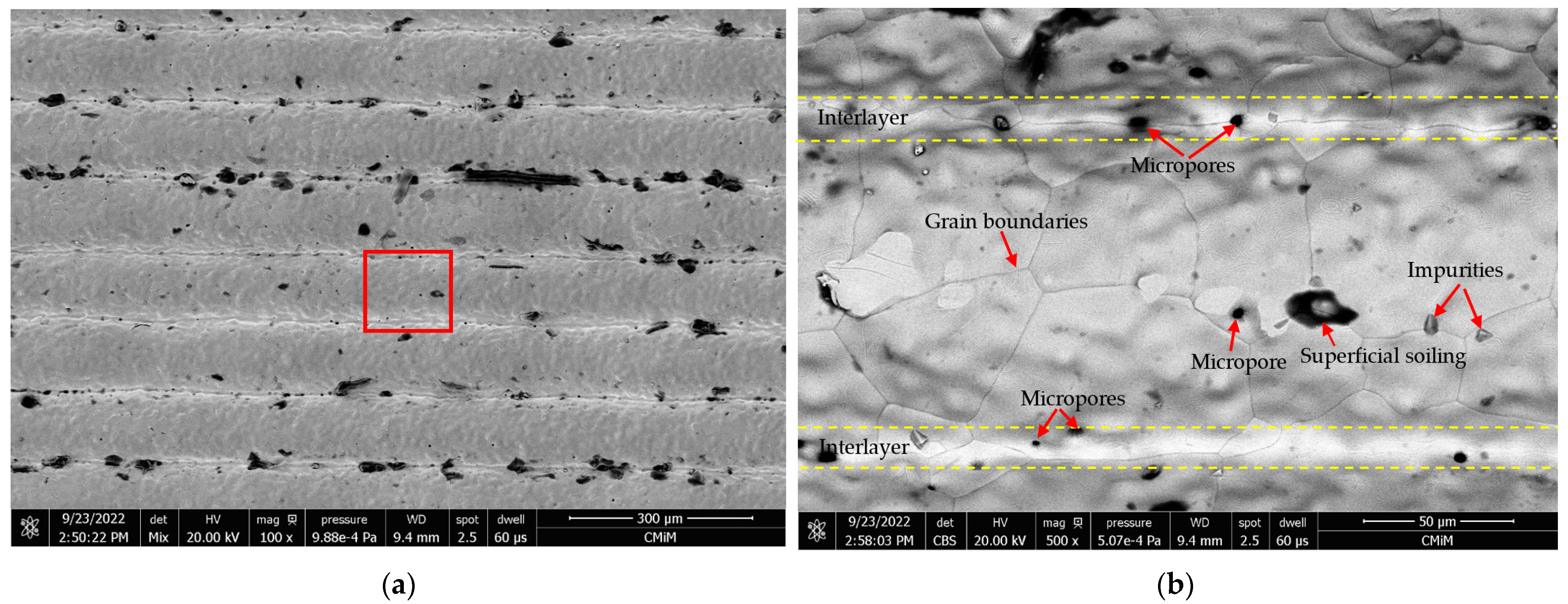
Figure 11 shows the SEM image of microstructure analysis of side surface at 100× and 500× magnification, mixing BSE and SE images, a spot size of 2.5 and a work distance of 9.4, respectively. Samples were analyzed directly on layered surface of side specimen without polish. Figure 11a shows a layered surface with 100× magnification. There are black spots trapped on the surface of the Inconel alloy which is a polymer that does not burn out during sintering. The deposition pattern in each layer looks regular with a uniform direction. The image also shows an interlayer with a lighter color visible on the surface. Figure 11b with 500× magnification shows the layer and interlayer areas more clearly. During the sintering process, solidification of the powder material occurs when grain boundary bonds between the constituent powders are formed. Bonding between grains occurs as a result of heating from the sintering process. The ADAM technology applied to the sintering process of the printed part looks like the result shown in the figure. The interlayer appears uniformly lighter along the surface. In the interlayer, there are micropores and impurities that arise after the sintering process. In the layer area, grain boundaries, micropores, impurities, and remnants of the unburnt polymer during sintering were clearly visible. This condition affects the mechanical properties of the Inconel 625 material built via FMEAM.
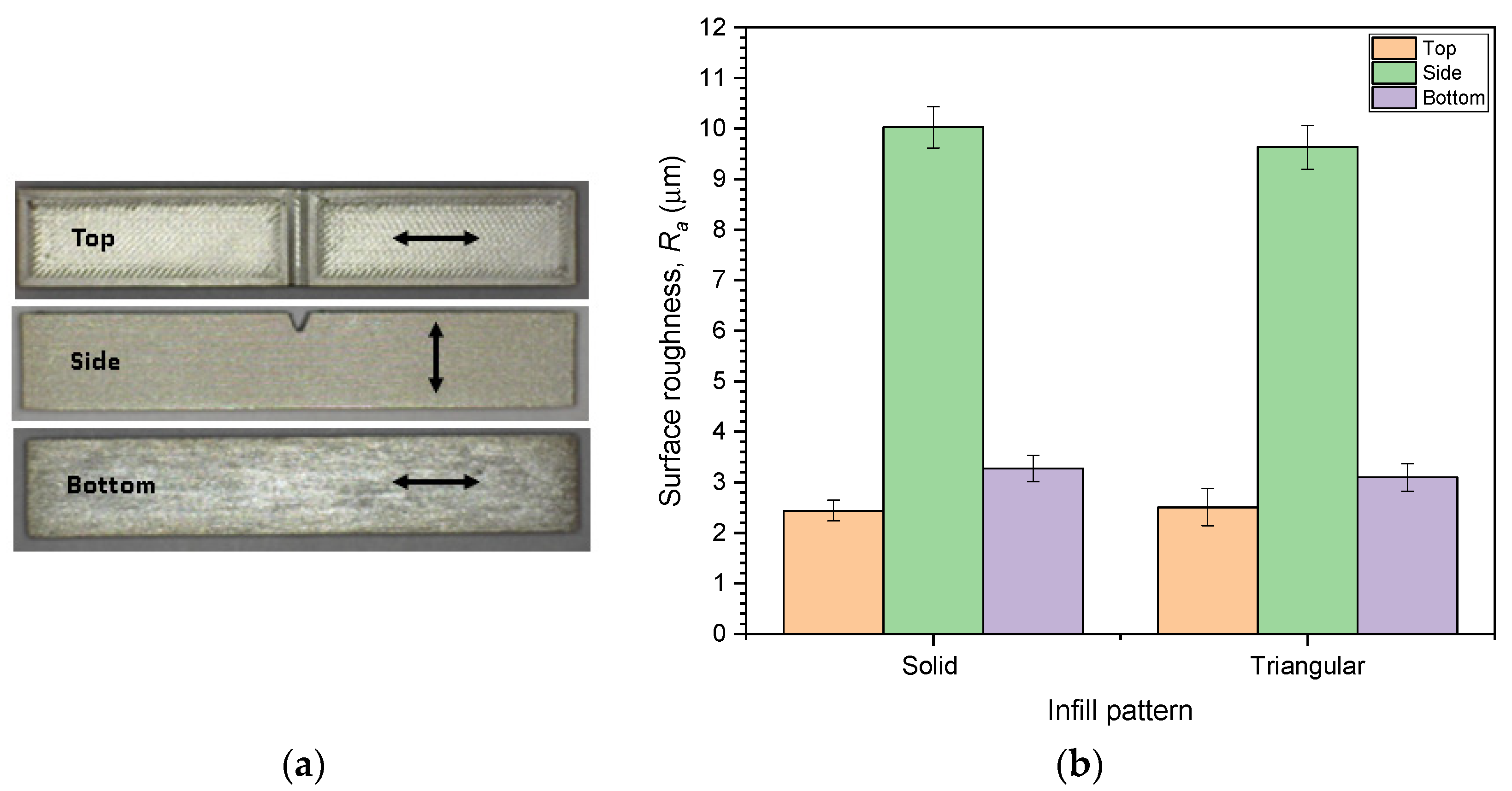
Figure 12 shows the surface roughness for the filament-based material extrusion additive manufacturing process conducted using the Inconel 625 material. The surface roughness of the sintered part produced was measured on the top, side, and bottom (Figure 12a) using a 5 mm length and the data were recorded five times. It was discovered that the side surfaces had 10.03 µm and 9.63 µm infill, the top had 2.44 µm and 2.50 µm, while the bottom had 3.27 µm and 3.09 µm infill, for the solid and triangular patterns, respectively (Figure 12b). This means that the surface roughness for the side surface was greater than the top and bottom surfaces due to its high layer of 0.125 mm. This is in line with the previous study that the layer thickness usually affects the surface roughness [42]. A similar observation was also made for the application of different process parameters and build direction. The top surface was observed to have a smoother surface quality than the others. It is pertinent to state that the manufacturing was conducted without a raft. Moreover, the average surface area was generally found to range from 2.44 to 10.03 µm and this means that the material extrusion manufacturing process with the Inconel 625 material is good enough for industrial applications with advanced processing or direct application.

4. Conclusions

This research was conducted to determine the effect of the infill pattern on the impact toughness, morphology of surface fracture and microstructure of layered surface of sintered part with the Inconel 625 material built via FMEAM as well as to investigate the characteristics of surface roughness. It was discovered that the solid infill pattern had the highest impact toughness, while the triangular infill pattern experienced a 57.6% reduction in impact toughness, but the two variations produced the same surface quality. The impact toughness value of MEAM manufacturing is still lower when compared to laser-based manufacturing. The thin lattice structure with large cavities in the triangular infill was found to have made it impossible for the material to withstand sudden loads. Moreover, there are micropores, impurities, and remnants of unburnt polymer during sintering, which affects the mechanical properties of the Inconel 625 material built via FMEAM. The micropores caused crack initiation and growth up to the moment where there was a final collapse. The findings also showed that the density produced was approximately 97.74% compared to the wrought material. Furthermore, the surface roughness values ranged from 2.44 to 10.03 µm on the bottom, top and front surfaces. These findings contribute to the current literature and can also be used to set the foundation for further related investigations, such as the effect of the thickness of walls, floors, and roofs with variations in orientation on impact toughness and fracture.

Author Contributions

Conceptualization, G.K. and A.K.; methodology, G.K. and A.K.; software, J.I.; validation, G.K., A.K. and J.I.; formal analysis, G.K.; investigation, A.K.; resources, J.I.; data curation, A.K.; writing—original draft preparation, A.K.; writing—review and editing, G.K.; visualization, J.I.; supervision, G.K.; project administration, A.K.; funding acquisition, G.K. All authors have read and agreed to the published version of the manuscript.

Funding

This research was funded by RIIM BRIN, grant number PKS: 97/IV/KS/11/2022.

Data Availability Statement

The data presented in this study are available in the article.

Acknowledgments

We are grateful to the National Research and Innovation Agency (BRIN) and Indonesia Endowment Fund for Education (LPDP) for funding this research (RIIM BRIN), as well as to Universitas Indonesia for their significant contribution.

Conflicts of Interest

The authors declare no conflict of interest.

References

  1. Oh, Y.; Witherell, P.; Lu, Y.; Sprock, T. Nesting and scheduling problems for additive manufacturing: A taxonomy and review. Addit. Manuf. 2020, 36, 101492. [Google Scholar] [CrossRef]
  2. Guan, X.; Zhao, Y.F. Numerical modeling of coaxial powder stream in laser-powder-based Directed Energy Deposition process. Addit. Manuf. 2020, 34, 101226. [Google Scholar] [CrossRef]
  3. Karami, K.; Blok, A.; Weber, L.; Ahmadi, S.M.; Petrov, R.; Nikolic, K.; Borisov, E.V.; Leeflang, S.; Ayas, C.; Zadpoor, A.A.; et al. Continuous and pulsed selective laser melting of Ti6Al4V lattice structures: Effect of post-processing on microstructural anisotropy and fatigue behaviour. Addit. Manuf. 2020, 36, 101433. [Google Scholar] [CrossRef]
  4. ASTM 52900-21; Additive Manufacturing—General Principles—Fundamentals and Vocabulary. ASTM International: West Conshohocken, PA, USA, 2021.
  5. Wang, K.; Ho, C.-C.; Zhang, C.; Wang, B. A Review on the 3D Printing of Functional Structures for Medical Phantoms and Regenerated Tissue and Organ Applications. Engineering 2017, 3, 653–662. [Google Scholar] [CrossRef]
  6. Meyers, S.; De Leersnijder, L.; Vleugels, J.; Kruth, J.-P. Direct laser sintering of reaction bonded silicon carbide with low residual silicon content. J. Eur. Ceram. Soc. 2018, 38, 3709–3717. [Google Scholar] [CrossRef]
  7. Gonzalez-Gutierrez, J.; Cano, S.; Schuschnigg, S.; Kukla, C.; Sapkota, J.; Holzer, C. Additive Manufacturing of Metallic and Ceramic Components by the Material Extrusion of Highly-Filled Polymers: A Review and Future Perspectives. Materials 2018, 11, 840. Available online: https://www.mdpi.com/1996-1944/11/5/840 (accessed on 12 January 2022). [CrossRef] [Green Version]
  8. Nurhudan, A.I.; Supriadi, S.; Whulanza, Y.; Saragih, A.S. Additive manufacturing of metallic based on extrusion process: A review. J. Manuf. Process. 2021, 66, 228–237. [Google Scholar] [CrossRef]
  9. Santos, L.S.; Gupta, S.K.; Bruck, H.A. Simulation of buckling of internal features during selective laser sintering of metals. Addit. Manuf. 2018, 23, 235–245. [Google Scholar] [CrossRef]
  10. Ratsimba, A.; Zerrouki, A.; Tessier-Doyen, N.; Nait-Ali, B.; André, D.; Duport, P.; Neveu, A.; Tripathi, N.; Francqui, F.; Delaizir, G. Densification behaviour and three-dimensional printing of Y2O3 ceramic powder by selective laser sintering. Ceram. Int. 2021, 47, 7465–7474. [Google Scholar] [CrossRef]
  11. Liu, S.-S.; Li, M.; Wu, J.-M.; Chen, A.-N.; Shi, Y.-S.; Li, C.-H. Preparation of high-porosity Al2O3 ceramic foams via selective laser sintering of Al2O3 poly-hollow microspheres. Ceram. Int. 2020, 46, 4240–4247. [Google Scholar] [CrossRef]
  12. Meyers, S.; Turón Vinãs, M.; Kruth, J.-P.; Vleugels, J.; Hooreweder, B.V. Laser powder bed fusion as a net-shaping method for reaction bonded SiC and B4C. Virtual Phys. Prototyp. 2022, 17, 854–863. [Google Scholar] [CrossRef]
  13. Yu, Z.; Zheng, Y.; Chen, J.; Wu, C.; Xu, J.; Lu, H.; Yu, C. Effect of laser remelting processing on microstructure and mechanical properties of 17-4 PH stainless steel during laser direct metal deposition. J. Mater. Process. Technol. 2020, 284, 116738. [Google Scholar] [CrossRef]
  14. Chen, B.; Su, Y.; Xie, Z.; Tan, C.; Feng, J. Development and characterization of 316L/Inconel625 functionally graded material fabricated by laser direct metal deposition. Opt. Laser Technol. 2020, 123, 105916. [Google Scholar] [CrossRef]
  15. Akbari, M.; Kovacevic, R. An investigation on mechanical and microstructural properties of 316LSi parts fabricated by a robotized laser/wire direct metal deposition system. Addit. Manuf. 2018, 23, 487–497. [Google Scholar] [CrossRef]
  16. Schur, R.; Ghods, S.; Wisdom, C.; Pahuja, R.; Montelione, A.; Arola, D.; Ramulu, M. Mechanical anisotropy and its evolution with powder reuse in Electron Beam Melting AM of Ti6Al4V. Mater. Des. 2021, 200, 109450. [Google Scholar] [CrossRef]
  17. Zhang, H.; Xu, J.; Wang, G. Fundamental study on plasma deposition manufacturing. Surf. Coat. Technol. 2003, 171, 112–118. [Google Scholar] [CrossRef]
  18. Javaid, M.; Haleem, A. Additive manufacturing applications in medical cases: A literature based review. Alex. J. Med. 2018, 54, 411–422. [Google Scholar] [CrossRef] [Green Version]
  19. Solomon, I.J.; Sevvel, P.; Gunasekaran, J. A review on the various processing parameters in FDM. Mater. Today Proc. 2021, 37, 509–514. [Google Scholar] [CrossRef]
  20. du Plessis, A.; Razavi, S.M.J.; Benedetti, M.; Murchio, S.; Leary, M.; Watson, M.; Bhate, D.; Berto, F. Properties and applications of additively manufactured metallic cellular materials: A review. Prog. Mater. Sci. 2022, 125, 100918. [Google Scholar] [CrossRef]
  21. Benedetti, M.; du Plessis, A.; Ritchie, R.O.; Dallago, M.; Razavi, S.M.J.; Berto, F. Architected cellular materials: A review on their mechanical properties towards fatigue-tolerant design and fabrication. Mater. Sci. Eng. R Rep. 2021, 144, 100606. [Google Scholar] [CrossRef]
  22. Greul, M.; Pintat, T.; Greulich, M. Rapid prototyping of functional metallic parts. Comput. Ind. 1995, 28, 23–28. [Google Scholar] [CrossRef]
  23. Galati, M.; Minetola, P. Analysis of Density, Roughness, and Accuracy of the Atomic Diffusion Additive Manufacturing (ADAM) Process for Metal Parts. Materials 2019, 12, 4122. Available online: https://www.mdpi.com/1996-1944/12/24/4122 (accessed on 7 March 2022). [CrossRef] [PubMed] [Green Version]
  24. Roshchupkin, S.; Kolesov, A.; Tarakhovskiy, A.; Tishchenko, I. A brief review of main ideas of metal fused filament fabrication. Mater. Today Proc. 2021, 38, 2063–2067. [Google Scholar] [CrossRef]
  25. Henry, T.C.; Morales, M.A.; Cole, D.P.; Shumeyko, C.M.; Riddick, J.C. Mechanical behavior of 17-4 PH stainless steel processed by atomic diffusion additive manufacturing. Int. J. Adv. Manuf. Technol. 2021, 114, 2103–2114. [Google Scholar] [CrossRef]
  26. Jagtap, B.M.; Kakandikar, G.M.; Jawade, S.A. Mechanical Behavior of Inconel 625 and 17-4 PH Stainless Steel Processed by Atomic Diffusion Additive Manufacturing. In Recent Advances in Manufacturing Processes and Systems; Dave, H.K., Dixit, U.S., Nedelcu, D., Eds.; Springer Nature: Singapore, 2022; pp. 583–594. [Google Scholar]
  27. Puppala, G.; Moitra, A.; Sathyanarayanan, S.; Kaul, R.; Sasikala, G.; Prasad, R.C.; Kukreja, L.M. Evaluation of fracture toughness and impact toughness of laser rapid manufactured Inconel-625 structures and their co-relation. Mater. Des. 2014, 59, 509–515. [Google Scholar] [CrossRef] [Green Version]
  28. Ramkumar, K.D.; Abraham, W.S.; Viyash, V.; Arivazhagan, N.; Rabel, A.M. Investigations on the microstructure, tensile strength and high temperature corrosion behaviour of Inconel 625 and Inconel 718 dissimilar joints. J. Manuf. Process. 2017, 25, 306–322. [Google Scholar] [CrossRef]
  29. Verdi, D.; Varadaraju, N.; Tan Zhi’En, E.; Patran, A. Effect of Manufacturing Strategy on the Toughness Behavior of Inconel 625 Laser Metal Deposited Parts. Adv. Eng. Mater. 2021, 23, 2001506. [Google Scholar] [CrossRef]
  30. Yan, X.; Gao, S.; Chang, C.; Huang, J.; Khanlari, K.; Dong, D.; Ma, W.; Fenineche, N.; Liao, H.; Liu, M. Effect of building directions on the surface roughness, microstructure, and tribological properties of selective laser melted Inconel 625. J. Mater. Process. Technol. 2021, 288, 116878. [Google Scholar] [CrossRef]
  31. Yuan, X.; Qiu, H.; Zeng, F.; Luo, W.; Li, H.; Wang, X.; Guan, N.; Cui, F. Microstructural evolution and mechanical properties of Inconel 625 superalloy fabricated by pulsed microplasma rapid additive manufacturing. J. Manuf. Process. 2022, 77, 63–74. [Google Scholar] [CrossRef]
  32. Gamon, A.; Arrieta, E.; Gradl, P.R.; Katsarelis, C.; Murr, L.E.; Wicker, R.B.; Medina, F. Microstructure and hardness comparison of as-built inconel 625 alloy following various additive manufacturing processes. Results Mater. 2021, 12, 100239. [Google Scholar] [CrossRef]
  33. Patterson, A.E.; Pereira, T.R.; Allison, J.T.; Messimer, S.L. IZOD impact properties of full-density fused deposition modeling polymer materials with respect to raster angle and print orientation. Proc. Inst. Mech. Eng. Part C J. Mech. Eng. Sci. 2021, 235, 1891–1908. [Google Scholar] [CrossRef]
  34. Kholil, A.; Syaefuddin, E.A.; Supardi, F.; Wulandari, D.A. The Effect of Layer Thickness on Impact Strength Characteristics of ABS and PLA Materials. J. Phys. Conf. Ser. 2022, 2377, 012001. [Google Scholar] [CrossRef]
  35. Shahwaz, M.; Nath, P.; Sen, I. A critical review on the microstructure and mechanical properties correlation of additively manufactured nickel-based superalloys. J. Alloy. Compd. 2022, 907, 164530. [Google Scholar] [CrossRef]
  36. Volpato, G.M.; Tetzlaff, U.; Fredel, M.C. A comprehensive literature review on laser powder bed fusion of Inconel superalloys. Addit. Manuf. 2022, 55, 102871. [Google Scholar] [CrossRef]
  37. Special Metals. Product Handbook of High Performance Nickel Alloys Special Metal. Special Metals Corporation. Available online: www.specialmetals.com (accessed on 21 November 2022).
  38. Waqas, A.; Xiansheng, Q.; Jiangtao, X.; Chaoran, Y.; Fan, L. Impact toughness of components made by GMAW based additive manufacturing. Procedia Struct. Integr. 2018, 13, 2065–2070. [Google Scholar] [CrossRef]
  39. Kazachenok, M.; Panin, A.; Panin, S.; Vlasov, I. Impact toughness of Ti–6Al–4V parts fabricated by additive manufacturing. AIP Conf. Proc. 2019, 2167, 020153. [Google Scholar] [CrossRef]
  40. Thompson, Y.; Gonzalez-Gutierrez, J.; Kukla, C.; Felfer, P. Fused filament fabrication, debinding and sintering as a low cost additive manufacturing method of 316L stainless steel. Addit. Manuf. 2019, 30, 100861. [Google Scholar] [CrossRef]
  41. Li, S.; Wei, Q.; Shi, Y.; Zhu, Z.; Zhang, D. Microstructure Characteristics of Inconel 625 Superalloy Manufactured by Selective Laser Melting. J. Mater. Sci. Technol. 2015, 31, 946–952. [Google Scholar] [CrossRef]
  42. Yasa, E.; Poyraz, O.; Solakoglu, E.U.; Akbulut, G.; Oren, S. A Study on the Stair Stepping Effect in Direct Metal Laser Sintering of a Nickel-based Superalloy. Procedia CIRP 2016, 45, 175–178. [Google Scholar] [CrossRef] [Green Version]
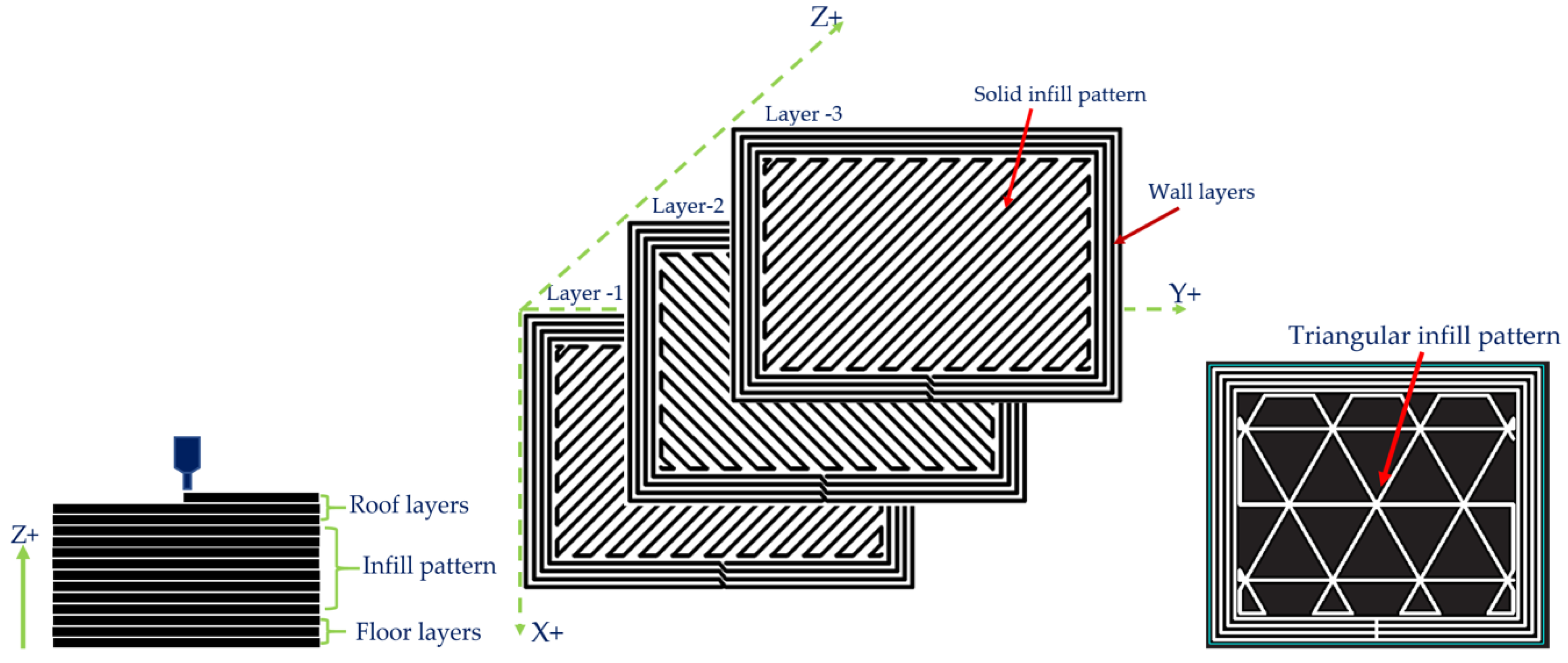
Figure 1. Infill-layer method of part built.
Jmmp 07 00114 g001
Figure 2. SEM images (a), and EDS spectrum (b) of Inconel 625 filament.
Jmmp 07 00114 g002
Figure 3. Dimension of ASTM E23 specimen.
Jmmp 07 00114 g003
Figure 4. Design of ASTM E23 specimen: (a) initial build orientation, (b) solid infill pattern, and (c) triangular infill pattern.
Jmmp 07 00114 g004aJmmp 07 00114 g004b
Figure 5. Specimens produced via filament-based material extrusion: (a) printed part, and (b) sintered part.
Jmmp 07 00114 g005
Figure 6. Specimens of impact test manufactured via MEAM with Inconel 625 filament: (a) top view, (b) bottom view, (c) side view, and (d) notch section.
Jmmp 07 00114 g006
Figure 7. Impact toughness for Inconel 625 built via filament-based material extrusion using solid and triangular infill pattern.
Jmmp 07 00114 g007
Figure 8. Fracture surface of Inconel 625 material built via filament-based material extrusion: (a) solid pattern, and (b) triangular pattern.
Jmmp 07 00114 g008
Figure 9. Morphologies of fracture surface of impact specimen built via filament-based material extrusion: solid infill pattern with magnification (a) 100×, and (b) 1000×.
Jmmp 07 00114 g009
Figure 10. Morphologies of fracture surface of impact specimen built via filament-based material extrusion: triangular infill pattern with magnification (a) 25×, and (b) 1000×.
Jmmp 07 00114 g010
Figure 11. SEM image of the side surface of Inconel 625 built via filament-based material extrusion with magnification: (a) 100× and (b) 500×.
Jmmp 07 00114 g011
Figure 12. (a) Line of measurement, and (b) Surface roughness of Inconel 625 material built via filament-based material extrusion.
Jmmp 07 00114 g012
Table 1. Composition of Inconel 625 filament.
ElementWt%At%
Ni45.721.7
Cr16.99.1
Mo7.02.0
Mn1.00.5
Al0.80.9
Si0.60.6
C28.065.2
MatrixCorrectionZAF
Table 2. Design process parameters in Eiger software.
AnnotationSolid InfillTriangular Infill
Printed dimension (mm)66.2 × 12 × 11.966.2 × 12 × 11.9
Final part dimension (mm)55.0 × 10.0 × 10.055.0 x 10.0 × 10.0
Print time3 h 6 m2 h 22 m
Wash time13 h 0 m8 h 0 m
Dry time4 h 0 m1 h 30 m
Printed part mass (g)50.9526.21
Final part mass (g)45.3823.35
Metal volume (cm3)9.284.77
Material cost (USD)15.317.88
Layer height (mm)0.1250.125
Wall layers44
Roof and floor layer-4
Layers7979
Disclaimer/Publisher’s Note: The statements, opinions and data contained in all publications are solely those of the individual author(s) and contributor(s) and not of MDPI and/or the editor(s). MDPI and/or the editor(s) disclaim responsibility for any injury to people or property resulting from any ideas, methods, instructions or products referred to in the content.