1. Introduction
The tooling industry supports the mass production of many parts via a range of mold-based processes, from sheet metal stamping to injection molding. In injection molding, the cooling portion of the process dominates the manufacturing cycle time, comprising 70–80% of the entire cycle time [
1]. Many strategies have been employed to increase the cooling capacity of injection molds, as even slight decreases in the cooling times can result in large decreases in manufacturing times when the effect is propagated over mass production [
2,
3]. The molds used in these processes are conventionally manufactured from billets using traditional metal cutting manufacturing strategies such as machining, drilling, and grinding. Conventionally, molds are cooled by cross-drilling the mold to create a path for cooling fluid that does not interfere with the structure or functional requirements [
4]. Alternatively, a hole is drilled perpendicular to the bottom of the mold and baffles are inserted to force the cooling fluid to travel to the bottom of the drilled hole, achieving cooling closer to the mold surface [
5]. The design of these molds is often limited by their machinability. For example, machine tools must have the proper reach and access to machine internal cooling channels. The machining stroke, or distance the machining center can travel, must be at least double that of the length of the drilled channel for the tooling to be oriented before the machining process begins. This often requires using long, fragile, expensive drills in a multi-axis machine tool. If the tool cannot reach the surface to remove material, it cannot be machined. Thus, it is often impossible for traditional manufacturing techniques to manufacture molds with complex internal geometrical shapes.
Conformal cooling, where the cooling channel is equidistant from all mold surfaces, is advantageous for complex molds due to its ability to closely follow the molding surface and maintain a minimum distance to the cooling channels. By decreasing the distance that the excess thermal energy must travel to the working fluid and increasing the consistency of the temperature distribution in the mold, higher-quality parts are made at a faster production rate [
6]. These advantages allow for an overall decrease in the component cooling time [
2,
7,
8]. By using only subtractive manufacturing techniques, conformal cooling channels can be achieved by machining a grooved shell that is then sealed on top of a smooth, inner die to direct the fluid around the surface, known as a milled-groove-type mold [
9]. To improve the cooling characteristics of the mold, the mold material can be varied by integrating solid cooling rods with a higher thermal conductivity material such as copper. However, as the material wear resistance is also critical in mold design, higher performance materials with better wear resistance are often used at the expense of thermal conductivity.
Unlike traditional, straight cooling channels, conformal cooling channels are curved, complex, and designed to improve the tooling performance. Conformal cooling channels were first developed by Sach et al. [
10,
11] and have since been shown to demonstrate superior characteristics in terms of their reduced warpage, shortened cooling time, and improved temperature uniformity compared to traditional straight-lined cooling channels [
12]. As shown by Oh et al., the use of conformal cooling channels produced by powder bed fusion reduced the overall cooling time by 40% when compared to traditional cooling channels [
13]. Various shapes of conformal cooling channels were studied by Hu et al., who concluded that a serpentine conformal cooling channel had the best cooling performance at a low Reynolds number [
14]. The low Reynolds number provides less turbulence and the highest coolant flow, both of which improve the heat transfer effect. The serpentine design can also enable the avoidance of critical mold assembly components, such as the ejector and alignment pins.
As the geometric complexity of cooling channel designs increases for increased thermal performance, the manufacturing strategy to make these molds becomes more difficult. Because of this, there have been several studies investigating the use of additive manufacturing [
15,
16]. Laser powder bed fusion (LPBF) is well-suited for the manufacturing of molds with complex cooling channels, but LPBF molds involve lengthy manufacturing times and are often limited to components with critical dimensions on the order of tens of centimeters. Commercial LPBF systems are also limited to a single material type, with the inability to easily make multi-material or graded components. LPBF also requires the post processing of the component through machining in order to achieve the required surface finish [
15]. This secondary finishing process increases the likelihood of dimensional inaccuracies due to setup errors, the need for another piece of specialty manufacturing equipment, and the need for more operators.
Unlike LPBF, blown-powder directed energy deposition (DED) allows for the manufacturing of functionally graded material, which could enable multi-material molds with customizable thermal conductivities in select locations. By incorporating highly conductive materials such as copper, the mold performance can be increased as much as 70% [
17,
18]. Recent studies by Kapil et al. and Pragana et al. have shown that conformal cooling channels can be produced with wire-arc DED [
19,
20]. Furthermore, DED enables the manufacturing of complex shapes that are impossible using traditional manufacturing techniques, such as machining, and at a size scale not seen with other additive manufacturing techniques, such as LPBF. However, there is little to no work on the manufacturing of conformal cooling channels with blown-powder DED.
Combining DED and machining in a single machine tool has enabled many advances in rapid manufacturing [
21]. Additive manufacturing allows for the quick buildup of large components, while the integrated machining enables the precise finishing of all surfaces for functionality [
22]. Wei et al. reviewed the use of hybrid manufacturing techniques to manufacture conformal cooling channels and determined that the manufacturability constraints for both the additive and subtractive processes must be considered when manufacturing hybrid components [
23]. Additive manufacturing is limited in its inability to manufacture overhung material without supports [
24,
25,
26]. Machining is often limited by the reach and access of the cutter [
27,
28,
29], and the minimum length scale [
30,
31,
32].
Another challenge in hybrid manufacturing is the implementation of a hybrid process planning technique [
23,
33]. Zheng et al. and Behandish et al. researched automated process planning for hybrid manufacturing, but these advancements are still limited to simple geometric shapes and 2.5 axis manufacturing strategies [
34,
35]. By leveraging the five-axis motion systems in advanced machine tools, it is possible to generate complex shapes with large overhangs using DED by rotating the deposition head relative to the part to deposit normal to the desired deposition location. However, little to no work has been done on generating complex hollow shapes, such as out-of-plane conformal cooling channels, especially where clearances are minimal between the component and deposition system. A study conducted by Soshi et al. used hybrid manufacturing to fabricate a mold with conformal cooling channels [
36]. This study used a scaffolding approach by cladding pre-machined blocks with conformal cooling channels but was limited to in-plane cooling channels with no curvature in the molding surface. While DED does not have the size limitations that LBPF does, most of the research on printing conformal cooling channels using wire-based DED is done in a vertical orientation [
37]. This is done to overcome issues with additively manufacturing overhung geometry, as well as to reduce the complexity of the toolpath generation. This approach, however, increases the amount of printed material and makes re-fixturing for machining more difficult.
The investigation conducted for this article addresses the current lack of knowledge in the field of hybrid manufacturing to produce out-of-plane conformal cooling channels in a horizontal configuration. The system used in this study was a blown-powder DED system, which opens the door for future work to investigate multi-material and gradient tooling applications. The study compared the design and performance of a tool with traditional (straight) and conformal cooling channels as well as presented a methodology for manufacturing a mold with embedded conformal cooling channels with a blown-powder DED hybrid manufacturing process.
2. Methodology
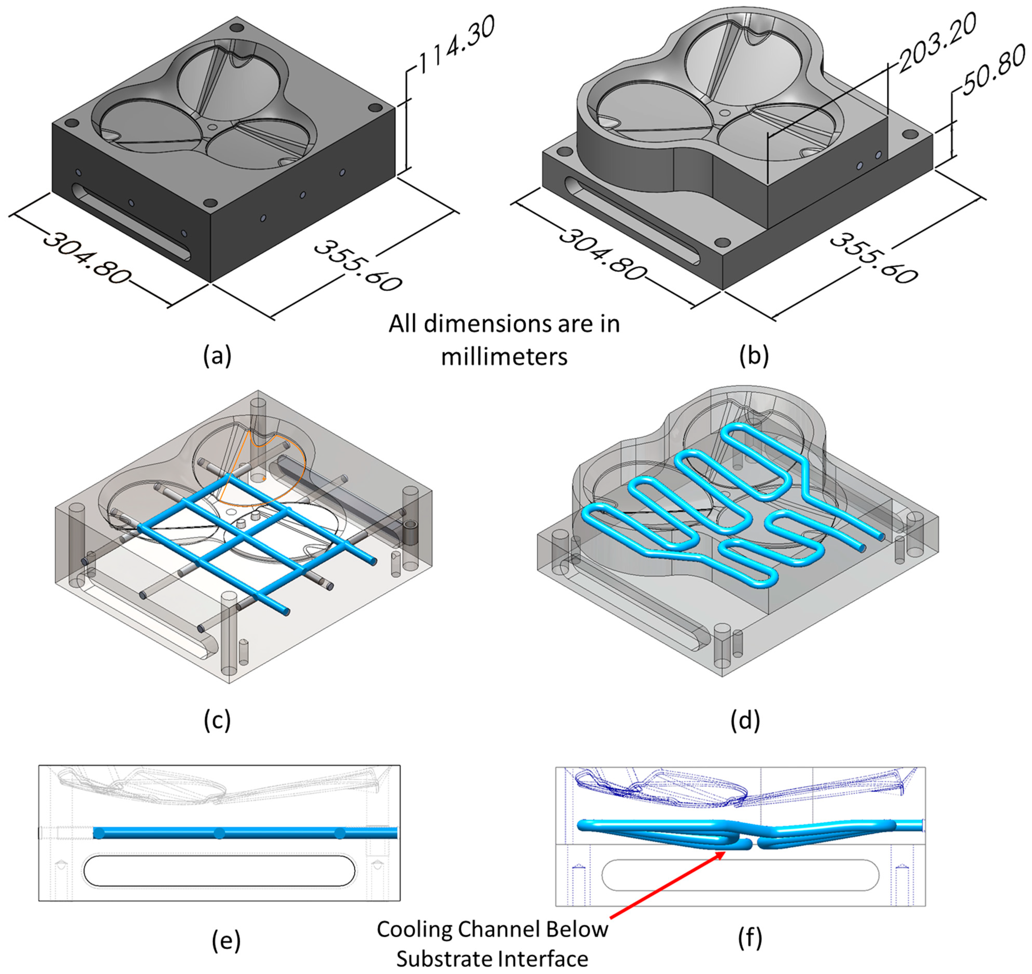
For this study, a compression molding tool was designed to manufacture three fuel door covers for an automobile. Two variations of the tool were designed to compare traditional versus conformal cooling channels, as shown in
Figure 1. The mold with traditional cooling channels manufactured with simple drilling operations is shown in
Figure 1a,c,e. The same molding cavity was then re-designed for additive manufacturing by fabricating only the necessary surfaces to reduce the overall weight, and by including conformal cooling channels, as shown in
Figure 1b. By leveraging additive manufacturing’s ability to easily make near-net shape components, the overall weight of the 316L stainless steel mold was reduced by 13.8%. This was achieved by optimizing the overall profile of the tool to minimize the amount of material required to manufacture the mold (refer to
Figure 1a versus
Figure 1b).
The conformal cooling channels, shown in
Figure 1d,f, were designed such that all the channel surfaces were equidistant to the molding surface throughout the path (refer to Figure 4a for the orthogonal section view of the conformal cooling channels). Since the conformal cooling channels are to be manufactured via additive manufacturing, the number of channels could be increased. The number of channels is only limited by the channel wall thickness and deposition head clearance. The traditional channel design was limited to six cross-drilled channels as there are limitations to cross-drilling without disrupting the flow of the cooling fluid as well as room for assembly components. By leveraging the capability of additive manufacturing to produce complex shapes, the overall length of the conformal cooling channel was increased. Comparing the volume of the channels, the conformal cooling channels held 69.3% more cooling fluid, which increased the energy removal potential as well. The authors note that more traditional cooling passageways could have been added to make the cooling channel volumes match. However, due to the mold this design was based on, the traditional cooling channels were limited to six. The authors note that the increased length of the conformal cooling channels would cause an increased pressure drop in the cooling fluid, which would require more energy (higher cost). However, the authors hypothesized that this additional cost would be offset by the improved cycle time offered by the conformal cooling channels. This economic analysis is a topic of future work but is outside of the current scope of this article.
To further minimize the amount of printed material needed, the bottom half of the lowest cooling channel was embedded into the substrate as shown in
Figure 1f, decreasing the required height of the additively manufactured material by approximately 5 mm. For clarity, the upper half of the mold assembly is not shown. The cooling channels for both mold designs were 9.525 mm in diameter and were designed for 3/8” National Pipe Thread (NPT) fittings which were utilized on the compression press where this mold was designed to operate.
To compare the performance of both mold designs, a computational fluid dynamics (CFD) simulation was conducted in 2022 SOLIDWORKS Flow Simulation. Both molds were tested using the parameters listed in
Table 1. An initial temperature of 80 °C was applied to the entire volume of the mold assembly, including the mold bottom, mold top, and 3 molded parts, simulating the preheating of the mold required to soften the feedstock plastic prior to compression. Water was used as the cooling fluid over a total simulated time of 300 s. The 316L stainless steel was used as the material for the mold and ABS plastic was chosen for the molded part for its commonality in the molding industry. A 1060 alloy was used for the dowel pins in the assembly but were disregarded in the simulation due to their negligible volume relative to the mold base. The temperature was held constant for 30 s simulating the compression time and then was subsequently allowed to cool via the cooling channels for the remaining 270 s. The exterior walls were treated as adiabatic with 0 μm of roughness. It was also assumed that no additional cooling occurred due to the surrounding air.
The gradient was analyzed based on the total simulation time by SOLIDWORKS, utilizing a volume goal for the temperature as well as a cut plot along the key features in plane. The mesh used was a volumetric grid with an average cell size of 0.01 m spacing. The mesh, temperature-dependent fluid properties, and non-temperature-dependent mold material properties are supplied as part of the
supplemental material to this article.
The mold design with conformal cooling channels was manufactured on an Okuma MU8000V Laser EX hybrid manufacturing system to demonstrate the feasibility of producing such a mold with blown-powder DED technology. The Okuma system is a vertical five-axis gantry system with blown-powder DED integrated with its standard machining and turning capabilities. The mold was printed on a 316L stainless steel substrate with size −106 + 45 µm 316L stainless steel powder produced by Oerlikon. The additive manufacturing process parameters used during this study are shown in
Table 2. These parameters were selected based on previous studies conducted at Oak Ridge National Laboratory. As discussed in this article, these parameters resulted in the ability to geometrically manufacture the mold. However, it was determined after cross-sectioning that even though these parameters are sufficient for printing with geometry in mind, they are not optimized for metallurgical properties. This tradeoff seen in hybrid manufacturing is further discussed in a recent review article by Feldhausen et al. [
34].
3. Computer-Aided Manufacturing Development
As discussed in the introduction, the current DED research focuses on printing conformal cooling channels in a vertical orientation. This reduces the complexity of the computer-aided manufacturing (CAM) process and enables the use of traditional slicing strategies. Thus, this article presents a novel DED strategy that enables the manufacturing of conformal cooling channels in a horizontal orientation. Similar to the research conducted on LBPF, this work enables the manufacturing of molds with conformal cooling channels at a size unobtainable by current LBPF technology. This section presents the model preparation and toolpath trajectory planning used to manufacture this tool design. For this work, the CAM software hyperMILL by Open Mind was used.
The substrate was prepared with a face milling operation prior to using a ball endmill to machine the cooling channel sections that intersect the substrate, as shown in
Figure 1f. The first additive operation was generated to print the section of the mold from the bottom up to the mid-section of the conformal cooling channel (refer to Figure 5a and the attached
Video S1). Most CAM software packages generate additive toolpaths coincident to the model surfaces, which is generally advantageous in applications where a slight overbuild is desired. Since the generated toolpath represents the center of a deposited weld, the modeled cooling channels were expanded to compensate for the radius of the deposited bead. As a result, the 6 mm cooling channel made with a 6 mm deposited bead was modeled as a 12 mm cooling channel in the software. The conformal channels were not co-planar, so a ruled surface was generated from the skeleton of the cooling channels. This surface was then used to limit the additive toolpath to the midpoint of the cooling channels. The outcome of this toolpath strategy is shown in Figure 5a. As shown in the figure, the ruled surface limitation cropped the generated toolpath such that the only geometry below the midpoint of the conformal cooling channel was additively manufactured.
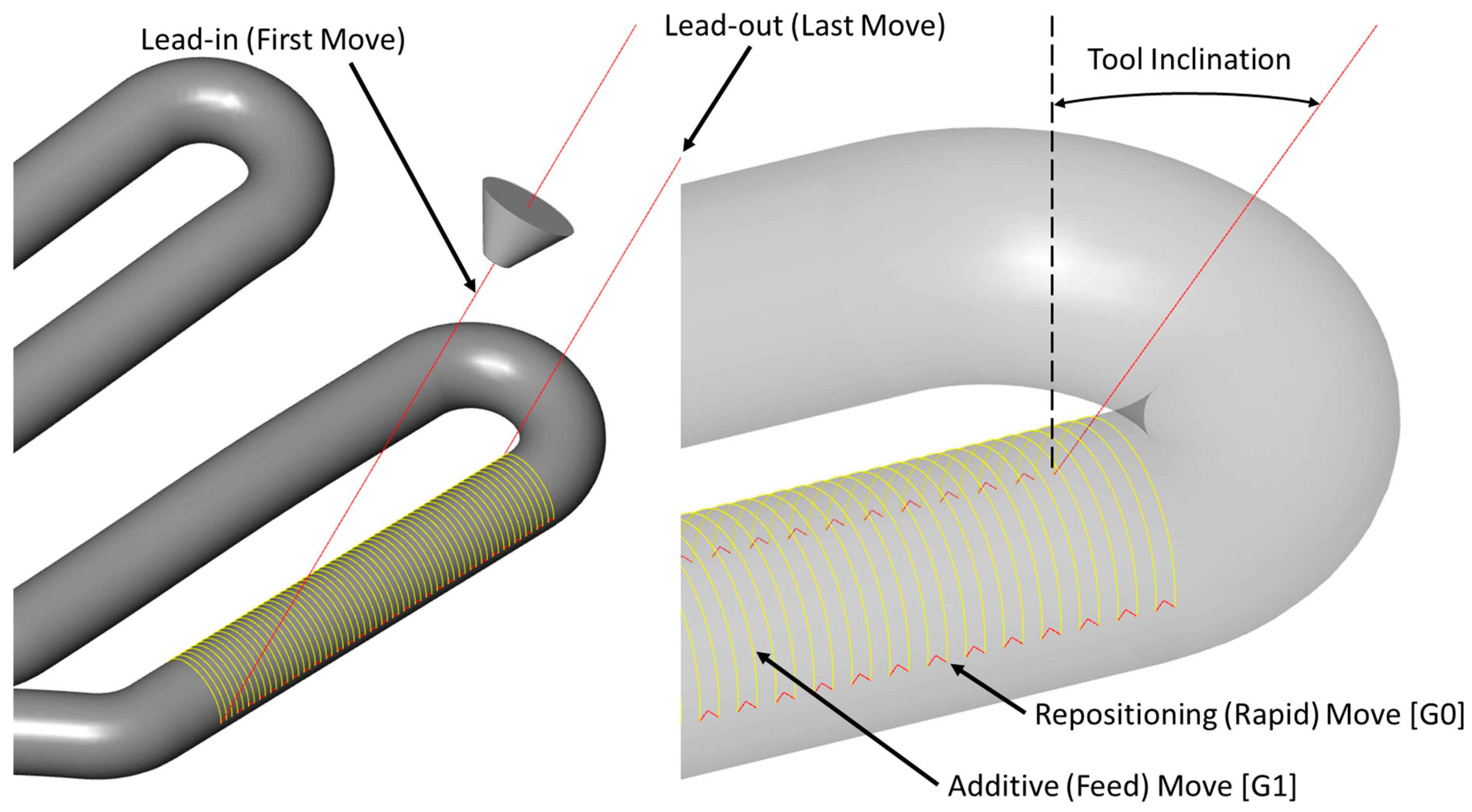
The cooling channel sections for the tool were classified as either linear or curved. For each classification, a different CAM strategy was employed. For the linear cooling channels, as shown in
Figure 2, a planar slicing method was used (refer to the
Video S2). All additive passes were equidistant and followed an isoparametric slicing strategy to the respective cooling channel. For alternate layers, the direction of motion was reversed to help reduce the non-uniform buildup due to the start and stop of the deposition tool path.
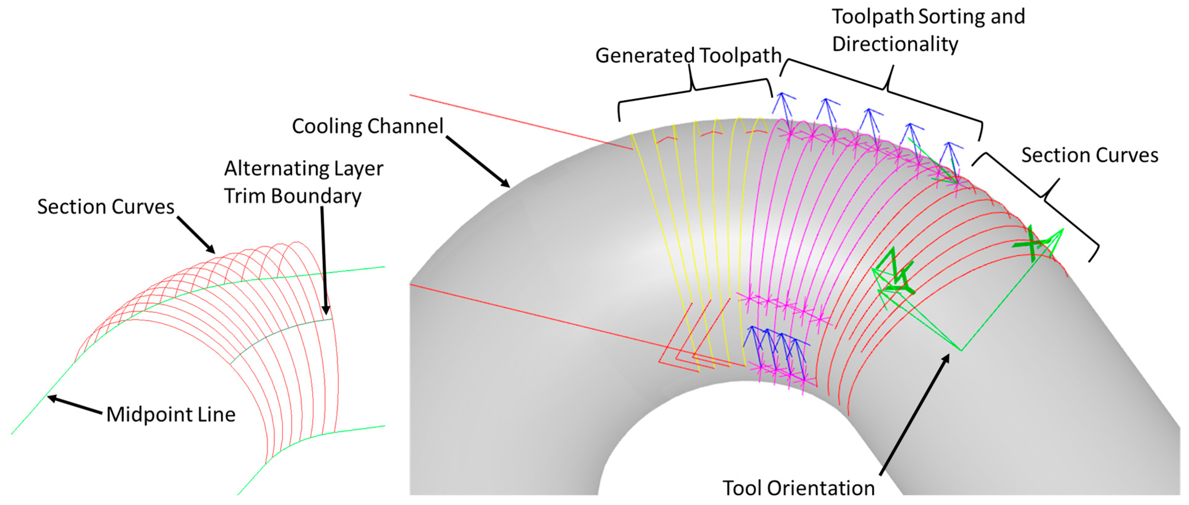
The curved toolpath trajectory, shown in
Figure 3, followed the expanded cooling channel surface in a sweeping motion (refer to the
Video S3). For each curved cooling channel, isoparametric section curves were generated such that the maximum distance between two consecutive curves was no greater than the designated stepover, or distance between consecutive weld beads. As shown in
Figure 3, each curve was trimmed such that it did not extend past the cooling channel midpoint. Furthermore, the alternating curves on the concave side of the cooling channel were trimmed due to their proximity to one another, to reduce concerns of overbuilding on one side. Like the linear cooling channels, the directionality of alternating layers was inversed. However, for the curved channels, it was discovered during manufacturing that it was preferable for each layer to start on the convex side of the channel. As shown by DeWitte et al., unidirectional printing strategies in directed energy deposition result in non-uniform buildup [
38]. In most cases where uniform slicing strategies are used, the above-mentioned non-uniform buildup is undesirable; however, in the case of the curved cooling channel where there is a non-uniform thickness between the deposited layers, this non-uniform buildup can be leveraged by starting each layer on the convex side of the channel to take advantage of the overbuilding tendency.
While generating the toolpath motion for the cooling channels, the tool inclination was assessed and modified for each section independently by using kinematic machine simulations. Three of these sections are shown in
Figure 3, each one showing a different state of the toolpath development. The section curves were generated by an isoparametric CAD operation and are shown in red. These section curves were used in a five-axis contouring toolpath operation for sorting and choosing directionality. Here, the pink lines correspond to the selected curves and the blue arrows correspond to the starting point and selected print direction along each respective curve. For simplicity, the directionality is shown as being reversed. However, as discussed, this was determined to be an incorrect strategy for the curved cooling channel sections. The generated toolpath shows the motion of the tooltip, where the yellow lines correspond to the movements made during the deposition [G1] and the red lines represent the repositioning [G0] movements. For the best results in the directed energy deposition, the deposition nozzle should be normal to the surface it is depositing on. In the case of the cooling channels, the nozzle is inclined as far as possible without causing machine collisions. For this specific mold, tool inclination was typically between 30° and 40°. Similar to the print strategy for the bottom section (refer to Figure 5a), a raster-style slicing strategy was employed to manufacture the rest of the mold. After printing, common CAM mold machining strategies were used to finish the mold surface. All the CAM was developed prior to manufacturing. However, as discussed in the ensuing section, the observations made during the manufacturing process proved to be invaluable to the success of this demonstration.
4. Results and Discussion
This article presents an approach as to how hybrid manufacturing can be used to produce a tool using blown-powder DED by additively manufacturing it in a horizontal configuration. This work addresses the current size limitations in LBPF, and wire DED’s inability to print overhung structures.
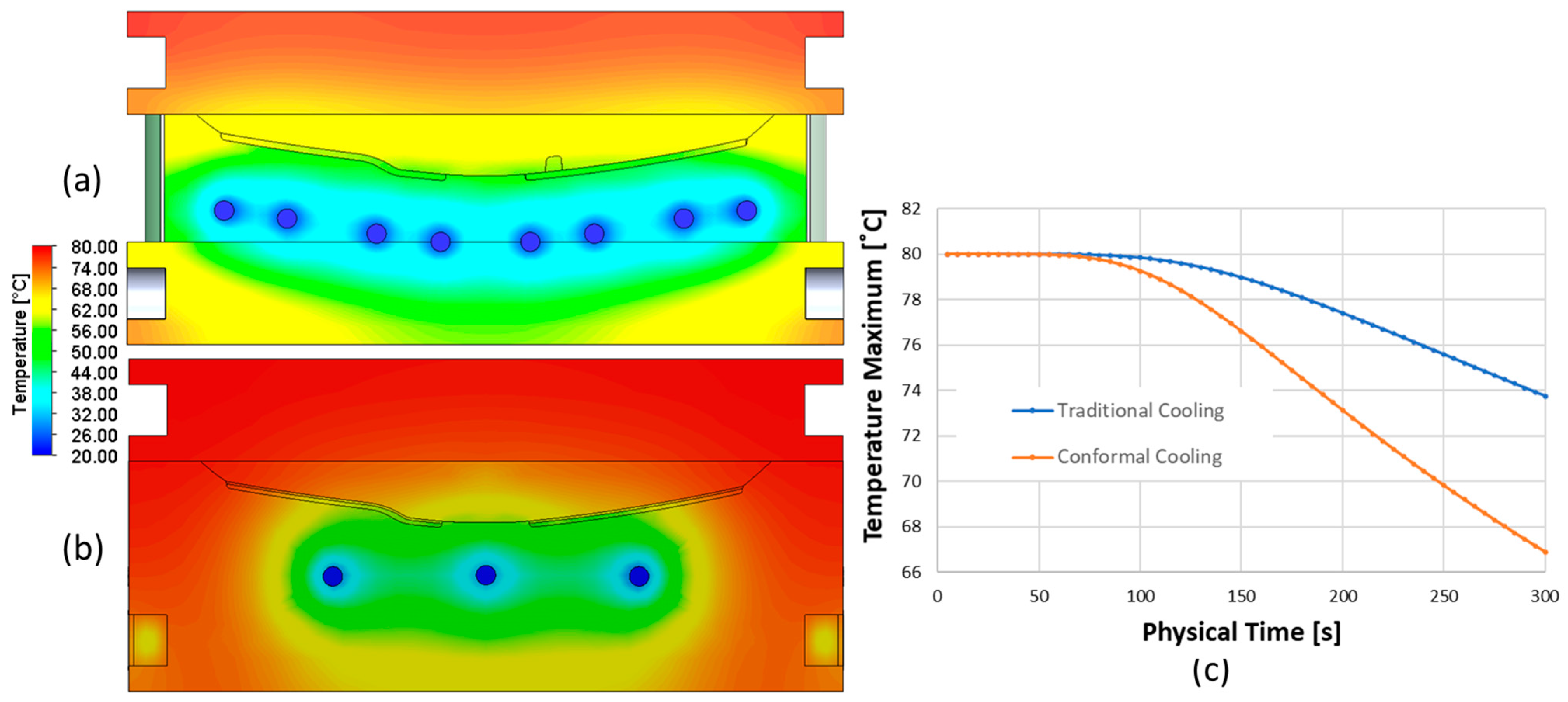
The CFD simulation results are shown in
Figure 4 with a cross-section taken at the center of the mold geometry. After 270 s of cooling, the maximum temperature of the molded component is plotted in
Figure 4c. The traditional cooling channels resulted in a maximum temperature of 74 °C, while the conformal cooling channels dropped to 67 °C. This 9.3% decrease in the final temperature indicated that the conformal cooling channels improved the cooling performance of the tool. During molding, a large portion of the overall cycle-time was driven by the cooling time. Thus, the overall manufacturing costs can be reduced if a mold of this size can be manufactured with the conformal cooling channels.
The simulation also assumed that the walls of the cooling channels are completely smooth. While this may be true for drilled cooling channels, features produced by additive manufacturing have a higher surface roughness. The authors hypothesize that this would enhance the heat transfer. However, this evaluation is a part of future work that is currently outside of the scope of work for this article.
Using the CAM strategy outlined in the previous section, the substrate was prepared using machining operations, and a planar deposition strategy was used to additively manufacture the mold up to the cooling channel midpoint without any issues.
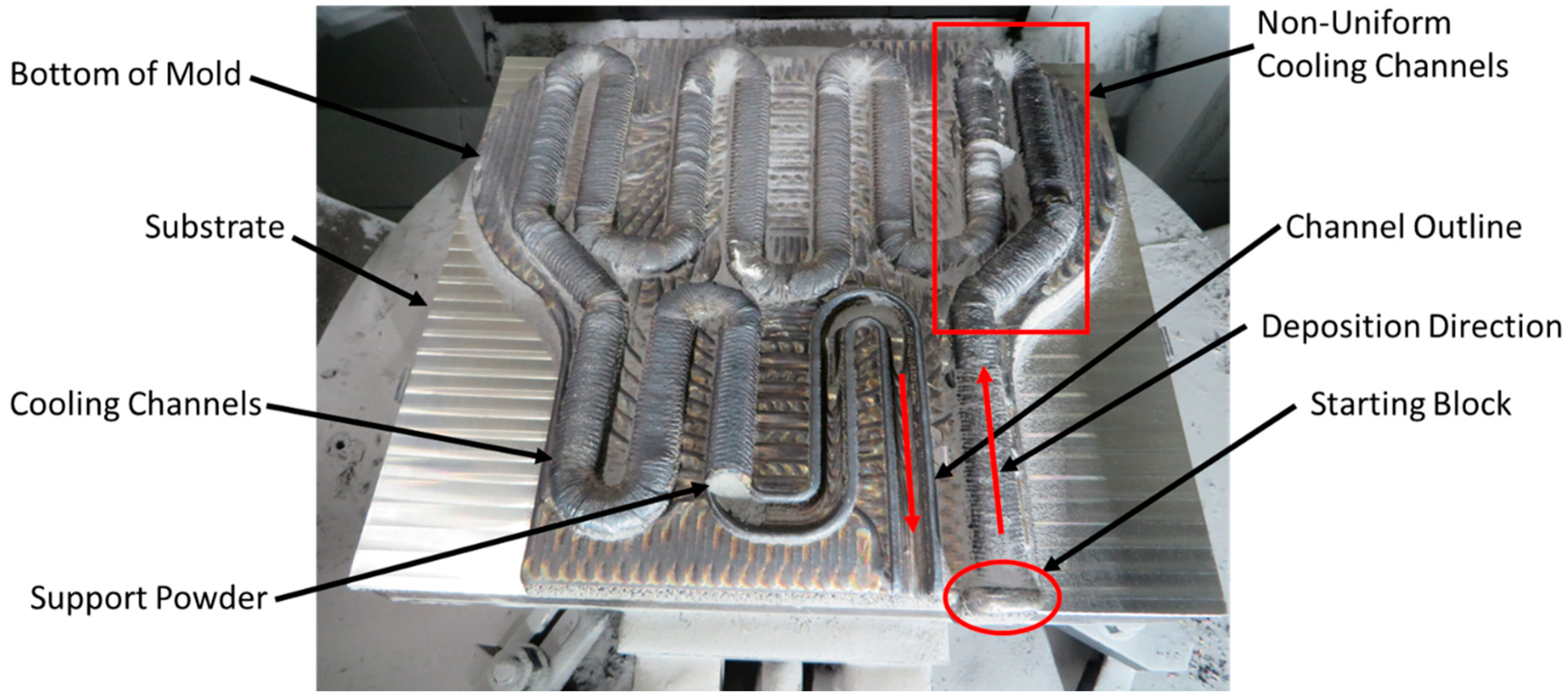
Figure 5 shows the mold in various stages of the manufacturing process. To provide support during the deposition process of the first cooling channel section, a rectangular prism (circled in
Figure 6) was deposited at the starting point of the arched cooling channel geometry. The additive toolpaths were comprised of various linear and curved sections, and each section was deposited discretely. This allowed the researchers to document, monitor, and make corrections to the toolpath during the manufacturing process. The first section deposited, a linear section, was deposited successfully. When complete, the excess powder was removed from the hollow structure and the next additive section was started.
After the successful deposition of the first section, the ensuing sections proved to be more challenging. As shown in
Figure 6, the first curved deposited section of the cooling channel (up until the second 180-degree turn) was non-uniform and uneven. Portions of these channels had to be machined away and re-deposited because the channels did not retain their structural integrity and collapsed during the print. Although the ability to repair a failed portion of the print is a benefit of hybrid manufacturing, it is still an unwanted outcome. To remedy the failure of collapsing, it was decided to keep the excess powder in the cooling channels between printed sections. The excess powder from the blown-powder DED process is often viewed as a disadvantage as the wasted material drives up the overall manufacturing cost [
39,
40]. However, this disadvantage turned out to be advantageous, as the excess powder acted as a support structure, similar to the bed of powder in LBPF. The manual removal of the powder after deposition of the first section caused the non-uniform printing of the subsequent sections. It is postulated that the excess powder that fills the channels during the deposition process helps support the hollow channel. This support powder may also help create a stable deposition condition by reducing the turbulent powder flow caused by gas flows directed into a closed, hollow structure. As shown in
Figure 6, the deposited cooling channels became uniform after the decision was made to leave the excess powder in the cooling channels.
It was also observed during the deposition trials of the non-uniform sections that large portions of the cooling channels delaminated from the bottom of the mold due to the compounded residual stresses from the DED process. While the excess powder served as a good support structure, the excess powder was mitigating good bonding between the deposited cooling channel and mold bottom. Excess powder trapped in the concave shape of the printed part absorbed too much laser energy and caused delamination. To remedy the delamination, a channel outline, shown in
Figure 6, was deposited prior to the cooling channel deposition as a bonding feature. After depositing the outline, no further delamination was observed.
During the deposition process for each cooling channel section, an 8 s dwell was added between each layer to mitigate concerns of collapse due to overheating. The machine operator also actively monitored the weld-pool shape via co-axial weld-pool imaging to help determine if a collapse had occurred due to thermal energy accumulation.
Once the cooling channels were deposited, the rest of the mold was deposited, as shown in
Figure 5c. To prevent overheating and collapsing of the channels, the laser power during the final deposition process was reduced from 3000 W to 2500 W. After the mold surface was machined, it was concluded that this reduction in the heat input resulted in a lack of fusion defects, as multiple pores were observed on the top machined surface. While this power reduction was a choice that the CAM programmer made during the toolpath generation, it proved to be a wrong one. This emphasizes the need for a better connection between the CAM programmer and the manufacturing process [
41]. Each decision made by the CAM programmer has a direct effect on the final part. Without generating the digital thread between the process and process planning, technology such has hybrid manufacturing may never be widely adopted.
After machining, the inlet and outlet of the cooling channel were threaded for 3/8” National Pipe Tapered (NPT) fittings, and the residual powder in the channel was removed. The mold was tested by connecting the cooling channel to a water source. Water successfully flowed through the mold, but the porosity observed in the top surface resulted in some leaking. For safety concerns due to the water leaks and to obtain a better understanding of the printed cooling channel geometry, it was decided to not use this mold in a molding application. The authors plan to incorporate observations from the first iteration and re-manufacture the mold in future work.
While excess powder is viewed as a major drawback in blown-powder DED, it proved to be invaluable during this demonstration. When finished, the powder removal from the cooling channels was slow and tedious. The use of water and wire pipe-cleaners were used in an interleaved fashion to remove the powder. The entire powder removal process took approximately 4 h. The team hypothesized that it may be possible to use other materials and strategies to provide support for DED components. For example, pre-manufactured tubing in the shape of the cooling channel can be inlayed into the channel and support the succeeding depositions. Furthermore, the use of polymer support structures in hybrid manufacturing has been shown to be beneficial for embedded electronics applications [
42]. It is postulated that researchers can build on this knowledge to use polymer support structures for the cooling channels and then remove the polymer using a solvent. By utilizing an intermediate structure to generate the support needed, it may be possible to remove the need for printing unsupported DED structures.
To further understand the delamination morphology and resulting geometry, the mold was cross-sectioned using a bandsaw. As shown in
Figure 7, most of the lack of fusion defects were between the top surface of the cooling channel and the subsequent deposition. By reducing the laser power to mitigate concerns of overheating the cooling channels to the point of structural failure, the authors introduced more defects than originally anticipated. As shown in
Figure 7, while the first deposited channel on the left side was the largest and most circular, there was significant delamination on the sides. This was due to excessive powder being trapped on the print surface. As previously discussed, this was later mitigated by depositing the channel outline (refer to
Figure 6). The internals of these channels were also cleaned of excess powder before it was determined that the excess powder in the channels was needed to support the molten metal during deposition. Once that was determined, the powder was manually placed back into the cooling channel cavity. Once these two modifications were made to the deposition process, as shown in the figure, the cooling channels had fewer defects and the overall shape and size became more uniform (refer to
Figure 6).
While this demonstration produced a tool with a single material composition, blown-powder DED has the unique capability of manufacturing multi-material components. Future work should include the exploration of generating multi-material tooling with graded material compositions. The use of multi-material in the tooling industry is not novel, but additive manufacturing has the potential to further enhance it. In addition to conformal cooling channels, veins of material with improved thermal conductivity can be used to further improve the heating and cooling performance. This concept further expands the design space of the tooling industry.


 ,
, 


