Abstract
The paper presents the microstructural characterization of the chip roots in high-speed steels and ceramic Ti3SiC2. The process of chip formation and the obtaining of adequate samples were carried out using the quick-stop method. The tests were carried out during the milling process; the “quick stop” method was carried out in order to obtain samples of the chip roots. This method was developed in-house by the authors. The chip roots were microscopically studied by means of a light microscope (LM) and a scanning electron microscope (SEM). Before the actual analysis, preparation was performed based on the standard metallographic technique. The analysis of the high-speed steels samples showed that, for the used cutting conditions, a discontinuous chip with a built-up edge (BUE) was formed. During the processing of the Ti3SiC2 ceramic, a significant difference was manifested in the chip formation process and a powder-like chip was produced. After utilizing a careful cutting process, a chip pattern was observed, from which it is evident that chip breakage during ceramic processing occurs without prior plastic deformation. In addition, the cutting force Fc was also measured during the milling process of the high-speed steels and the ceramic, and it was correlated with the cutting speed, feed per tooth and depth of cut.
1. Introduction
Today, when presenting different models that describe the metal cutting process, researchers largely overlook the characteristics of material properties. The lack of a reasoned analysis of the stress–deformation relationship during cutting and the formation of the chip root is particularly noticeable here. The simplified macroscopic approach that extends through scientific research studies encounters major problems when describing the cutting process in depth [1,2]. This lack of more detailed analysis is seen through the presentation of 2D or 3D models of the chip root, where the emphasis is on the thermodynamic and geometrical analysis of the chip formation. Nowadays, software support analysis based on the finite element method enables the simulation of segmental chip formation during various cutting processes [3,4,5,6,7,8,9]. The design of the segmentation process on the opposite side of the chip root is achieved by entering the appropriate mechanical properties of the tested material. This initial parameter input primarily refers to the data that describe the in-bulk deformation of the samples, i.e., the material characteristics of overall strength and deformation (modulus of elasticity, yield stress, tensile strength, elongation, hardness, etc.). However, during real testing, deviations occur between the actual microscopic images of the deformation state and the models obtained on the basis of finite elements. These deviations do not have to be significant, but certainly in terms of accuracy researchers must rely on expanded experimental analyses [10].
The research reported in the literature is very extensive regarding the examination of the chip formation process, and the summary of relevant finding is given in the following paragraphs.
In study [11], the influence of variable cutting speed on the chip formation process was analyzed the authors, and they obtained different cyclic chips with a continuous increase in the cutting speed. In addition to the speed test, research based on the application of the compression split Hopkinson pressure test, where samples of chip roots during the cutting process were analyzed, can also be noted. The aim of that study was to determine the material stress properties of the chip formation during machining of AISI 1045 steel (eqv. EN C45E) [12].
A further insight into chip formation can also be obtained through ultra-precise processing, i.e., processing at the microscale level. Here, there are studies that have dealt with the process of cutting soft materials, such as some types of pure copper or brass. At this ultra-precise level of processing, it has been observed that the crystallographic orientation has a great influence on the chip formation process [13,14]. However, most materials do not have a fully uniform structure but consist of several different phases that can make it difficult to analyze the cutting process, whether it is on a micro- or macroscale.
In study [15], the authors showed that even the two-phase microstructure of steel can be a problem for analysis. This is reflected in the example of the different properties of the phase grains of the material, which during the microcutting process have an impact on the quality of the final processing, specifically when processing Ck45 steel (eqv. AISI 1045, EN C45E) during the milling process.
Furthermore, research on the final processing and examination of the treated surface on a micro- or macroscale can be used. In this study, for the examination of the chip formation, the authors used the mesoscale, where they observed different depressions in the machined surface. For this approach, heterogeneous models, described with the help of finite element methods, were used [16].
Unlike heterogeneous models created on the basis of finite elements, homogeneous models showed a much better perception of experimental data. Thus, in a study that dealt with tests on the steel AISI 1045 (eqv. EN C45E), and where models of chip formation with a very precise homogeneous structure were obtained, it was found that there is an agreement with conventional models realized on the basis of the sample microstructure [17].
When the investigation of chip root formation during milling is considered, paper [18], which dealt with research into orthogonal milling with a different range of speeds that did not exceed 30 m/min, needs to be mentioned. These tests did not require changing the configuration of the machine tool, although samples of relatively small dimensions were obtained. These experiments were performed on the titanium alloy Ti-6Al-4V as a representative of hard-to-machine materials. The presented results were used for the rectification of the chip morphology with an emphasis on the mechanism of its formation. The authors were able to present the influence of cutting forces on the process of teeth formation on the edge of chips.
The literature article [19] explains the tribological behavior of the tool/chip contact pair from the aspect of friction observed immediately in front of the cutting edge of the tool. The instrumentation used here made it possible to observe the friction simulation process on the surface of the chip or tool. During this test, a friction indicator was used, whose role was to perform friction over the sample (the chip) at a constant speed. This methodology made it possible to further investigate the trail that was created based on the residual friction.
In addition to tests on conventional materials, the literature review also records research on modified new materials, such as hardened tool steel with an extremely high hardness, about 55 HRC [20]. These materials have found application in the tool industry, where they are characterized by extremely good mechanical properties that enable the high durability of tools. Research on this difficult-to-work material was carried out in order to study the influence of variable parameters during processing on the string. The feed, cutting speed and depth, which are adjusted on the machine, were varied, while the cutting width was examined by modifying the tool position itself. These parameter variations made it possible to gain insight into the mechanism of tool wear when cutting Uddeholm (Hagfors, Sweden) Impax HI Hard steel (modified AISI P20), as well as the influence of chips, by means of a scanning electron microscope.
The influence of surface shear stress on the chip morphology is presented in article [21]. The authors show the influence of contact pressure on the cutting force and compare it with experimental results, where deviations of less than 10% were obtained.
In addition to conventional low-speed processing, with the development of machine tools, research also began on high-speed processing, as shown in article [22]. The authors examined the machinability of hardened steel of high hardness, from 51 to 62 HRC, from the aspect of chip formation. A continuous and serrated chip is observed depending on variable parameters such as axial depth of cut, speed and feed. According to the experiments, conclusions were drawn that chips of different hardness can be controlled as a function of an adequate choice of the variable parameters.
In addition to variable parameters on the machine, research has also been focused on the influence of the cutting tool on the shape and morphology of the chip. A different radius of the tip of the tool, which changes from the aspect of wear, certainly affects the process of deformation of the processing material, as shown in study [23]. During the processing of the Ti-6Al-4V alloy, the influence of a sharp tool, i.e., a worn one, on the degree of chip segmentation caused by different types of deformation is shown.
Klocke et al. [24] set the axioms of theoretical research on orthogonal metal cutting. Their theoretical analysis starts from the simplest approaches to the entry of the tool material into the workpiece material, all the way to the most complex forms. Through these different forms of action of the tool on the workpiece, different characterizations of the chip formation process are theoretically described, from the point of view of the deformation zone, friction between the tribological pair tool/workpiece, temperature in the cutting zone, etc. In addition, the effects of processing parameters are described, among which the increasing effect of the feed on the shape of the edge during unstable chip formation is highlighted.
The influence of the microstructure, with an emphasis on the mechanics of chip segmentation, was investigated by the authors in study [25]. The main issue in this paper was the microstructural analysis of the fracture that was observed during the formation of the discontinuous chips. The propagation of the fracture was clearly manifested in the α–β phase during titanium processing at high cutting speeds. As the cutting speed increases, the ductility of the material also increases, due to the increased temperature. This phenomenon leads to the propagation of the fracture on the outer surface of the chip, which acquires a continuous bond with pronounced segmentation along the grain boundaries.
The dynamics of chip formation during orthogonal cutting of titanium alloys was also investigated by the authors in study [26]. A high-speed imaging system was used to investigate chip segmentation geometry, segmentation frequency and critical strain.
Based on the science that deals with the deformation of materials, that is, the theory of plasticity, new postulates relating to narrow areas of deformation are established. This primarily refers to the areas of chip root formation and the effect of fracture formation [27].
The directions of research into the chip formation process are oriented towards clarification of the mechanism under which material separation occurs, i.e., clarifying the most influential factors at work. Great importance is given to the research of cutting forces. In this sense, the aim of this paper is to study the process of chip formation when cutting high-speed steels and the ceramic Ti3SiC2, materials that are difficult to process, and to explore where specific mechanisms of chip formation could be obtained. Furthermore, chip formation will be correlated with the parameters of the cutting process, such as the resulting force, and then depth, feed and cutting speed. In this paper, the authors provide answers to the principles of chip formation in multiphase materials, as well as the effects that influence the mechanism of fracture formation, based on metallographic observations. In addition, the ratio of the resulting cutting forces is shown, which gives a comparative view of the machinability of the high-speed steels and the special ceramic Ti3SiC2.
By comparing the machinability of high-speed steels and the ceramic Ti3SiC2, in addition to new information about the process of chip root formation, we intend to point out the possibility of the implementation of ceramics in areas where only high-quality steels were represented until now. As an example, there is the growing phenomenon of making cutting tools, where ceramic materials have also found extensive application. Furthermore, the high thermal resistance of ceramics additionally demands that focus should be given to experimentally investigating these ceramic materials.
2. Presentation of the Chip Formation Model
The distinct complexity of phenomena in the cutting zone makes it impossible to set up a reliable, simple and comprehensive mathematical model of the stress and deformation state, based on which the principle and mechanism of chip formation during cutting can be known and explained. Among the developed theoretical schemes, some characteristic models of chip formation can be singled out, which are shown in Figure 1.
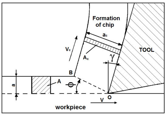
Figure 1.
Graphic representation of chip formation.
According to the model shown in the Figure 1, it is assumed that the entire plastic deformation takes place along one straight OB, which is at an angle . This allows the entire complex process of plastic deformation to be represented by a simple process of continuous successive slips of shear deformations. From the perspective of this model, the layer of material below the plane OB is undeformed, and the layer above the plane is completely transformed into a chip.
The importance of the shear angle in the science of cutting, and especially in the theory of machinability, is very great. This angle represents the basic characteristic of the cutting process because it defines the direction of plastic deformations in the shear plane. It is also used as a criterion for assessing the machinability of the material: with larger values of the angle , a higher quality of the machined surface, a lower cutting resistance and a strip shape of the chip is obtained, and vice versa.
Based on this model, it is possible to define the sizes of plastic deformation:
Starting from the theory of plasticity, materials science and the results of experimental tests, the general flow of the cutting process can be divided into three characteristic phases:
- (i)
- Phase of initial (elastic) deformation;
- (ii)
- Phase of plastic deformation of the cut layer;
- (iii)
- The phase of destruction of the material by the formation and removal of chips.
Processes on the contact surfaces of the cutting tool (friction, wear, etc.), the deposit phenomenon and other phenomena contribute to the fact that the exposed models of chip formation represent approximate and very simplified models of the cutting process. Figure 2 shows some of the possible phenomena during chip formation. In addition to the deformation of the material layer in the shear zone, deformation also occurs along the rake surface, where certain types of deposit are created due to the adhesion process. In addition to these phenomena, there are also other deformation zones that, due to the stress of individual phase grains, lead to the appearance of microcracks and, later, cracks.
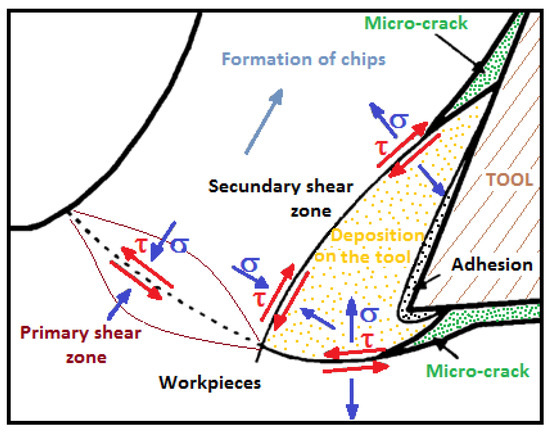
Figure 2.
Influential factors and processes occurring during chip formation.
It follows from this that, even under the best cutting conditions, chip formation takes place with intense plastic deformation of the affected layer in a localized area, resulting in large deformation strengthening, structural changes and, finally, chip breakage.
Therefore, knowing the behavior of materials during the chip formation process is the only way to understand the main economic and practical problems related to processing speed and tool durability.
3. Experimental Procedure
In this study, the following materials were used as workpiece materials during cutting: the high-speed steels HS 6-5-2-5 and HS 6-5-2C (designation according to the EN ISO 4957 standard) and Ti3SiC2 ceramic [28], produced in the Department of Materials Engineering, Drexel University, USA. The reason for the comparison of these two materials is that ceramics can be used as a replacement for high-speed steel due to their properties. Ceramic is applied in contexts in which its high temperature resistance, wear, resistance to corrosive environments and oxidation, and like steel electrical conductivity is required. It is used in the space and air industry as well as in other industries. The chemical composition of high-speed steels is presented in Table 1, while the composition of the ceramic Ti3SiC2 is given in Table 2. The mechanical properties of the Ti3SiC2 ceramic were as follows: compressive strength of 600 MPa, hardness of 4 GPa (approximately 408 HV) and Young’s modulus of 320 GPa [28]. According to the literature [28], the Ti3SiC2 ceramic is relatively soft, but reasonably stiff, and it is considered to possess a high fracture toughness. Furthermore, authors state that it is readily machinable as graphite and that it is probably self-lubricating.

Table 1.
Chemical composition of HS steel (mass. %).
Table 2.
Chemical composition of ceramic.
The experiments were performed on a vertical milling machine with a milling head. The samples were obtained after a quick stop of the milling process, and then they were prepared for metallographic analysis. The process of obtaining samples requires the creation of identical test specimens, in order to fulfill the reproducibility of the results. The method of stopping or breaking samples is based on cracking the weakest part of the test specimen using excessive cutting force. This method of obtaining adequate samples was developed by the authors of this article [27,29].
A schematic representation of obtaining samples of the root of the chips during the milling process is given in Figure 3. When obtaining these samples, great precision is required in determining the minimum section of the test specimen (Amin) at which cracking will occur due to excessive cutting force in relation to the strength of the processing material. The tool is placed orthogonally in relation to the obtained sample, in order to obtain the same geometry in each section along the root of the chip. As a cutting tool, rotating inserts made of quality hard metal were used, with the following characteristics: rake angle γ = 0°, clearance angle α = 11°, l = IC = 12.7 mm, s = 3.18 mm, bs = 1.4 mm and bε = 1.4 mm.
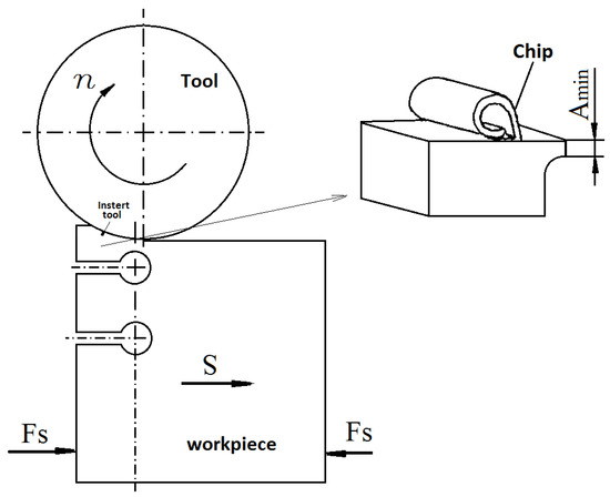
Figure 3.
The process of obtaining a chip root sample during milling.
The correct selection and preparation of the samples in almost all conditions is of crucial importance. Certainly, material testing is an important step in the quality control process of almost all production cycles. The purpose of macro- and microstructure examination is to reveal the morphology, characteristics and type of the material structure. In the course of this research, the samples were microstructurally examined after standard metallographic preparation: SiC paper grinding (grid from 220 up to 2500), and diamond suspension polishing (diamond grain size of 6, 3, 1 and ¼ μm), were used. The microstructure was revealed by etching with 3% nitric acid solution in alcohol (3% nital). All specimens were examined with a Leitz Orthoplan (Wetzlar, Germany) light microscope (LM) or with the scanning electron microscope (SEM) JEOL JSM35 (Tokyo, Japan) with an acceleration of 25 kV. Furthermore, SEM was used also for macroscopic examination of unprepared chip roots.
When detecting cutting forces, a standard three-component dynamometer type 9257A (Kistler, Wien, Austria), which works on the principle of piezo crystal sensitivity, was used. The signals detected in this way are transmitted by specially insulated cables to the computer, where their computer data processing is performed. On this transmission path, it is necessary to translate and amplify the detected signals into an appropriate size that is understandable by an analog-to-digital converter. The device that converts these signals (pico-coulombs into millivolts) is a multichannel amplifier, type 9257A (Kistler, Wien, Austria). In this way of transmitting the signal from the dynamometer, it is also necessary to use the multifunctional board ED 428 (Electronic Design, Beograd, Serbia), in which the immediate conversion of analog to digital signal and vice versa is performed. In this measuring chain, the signals can be increased in the range from 1 to 100. When implementing this instrumentation, it is necessary to set the direction of sensitivity from the aspect of compressive or tensile forces that are manifested on the dynamometer. This type of force is adjusted using jumpers that have the following options: ±5 V, ±10 V, 0–5 V and 0–10 V. In the case of the milling process, where non-alternating positive or negative loads occur, it is necessary to adjust the jumper to the sensitivity of ±10 V.
Monitoring was supported by a computer and adequately developed software for experimental data processing and storage (Figure 4). The dynamometer was mounted on the table of the vertical milling machine and the cutting tool of the face mill was 125 mm in diameter with one cemented carbide insert. Different cutting parameters were tested at intervals: cutting speed v = 1.8 to 3.7 m/s, feed f = 0.145 to 0.223 mm/tooth and depth of cut a = 0.7 to 1.5 mm. The cutting force sampling frequency was 400 samples per second.
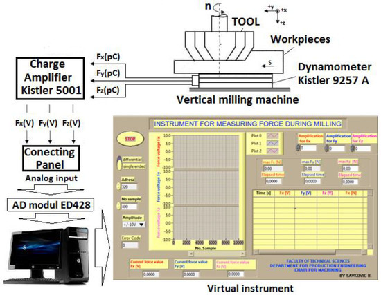
Figure 4.
Acquisition system for cutting force measurement.
4. Results and Discussion
After macro- and microscopic observation of the obtained chip roots for high-speed steels, it can be concluded that they were very similar; see Figure 5 and Figure 6. This is primarily reflected in the length of the chip, which was short, and also in the method of breaking, which was extremely easy. From the aspect of the chip continuity, it can be stated that the obtained chip was discontinuous. All produced chips were accompanied by the intensive plastic deformation and material fracture.
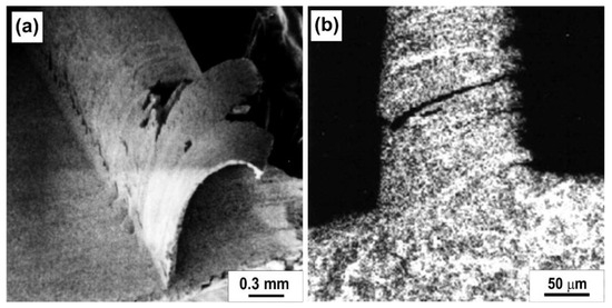
Figure 5.
Chip root of high-speed steel HS 6-5-2-5: (a) SEM and (b) LM; cutting conditions: v = 0.47 m/s, f = 0.088 mm/t and a = 4.3 mm.
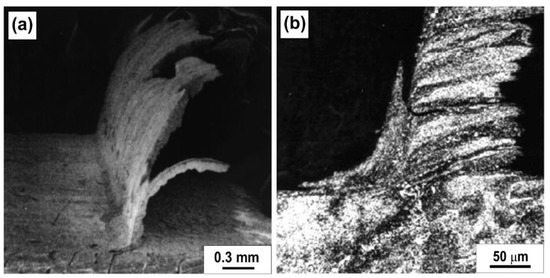
Figure 6.
Chip root of high-speed steel HS 6-5-2C: (a) SEM and (b) LM; cutting conditions: v = 0.37 m/s, f = 0.141 mm/t and a = 3.8 mm.
The microstructure of the high-speed steel HS 6-5-2-5 chip root produced during cutting is shown in Figure 5. The appearance of the built-up edge and the difficult plastic deformation of the cutting layer influence the poor quality of the workpiece surface roughness and the higher values of the cutting forces. This places the high-speed steel HS 6-5-2-5 in the group of difficult-to-machine materials.
The second type of high-speed steel HS 6-5-2C is shown in Figure 6. With this steel, a more intensive occurrence of material deposition at the chip root (BUE) was observed. These phenomena are related to the chemical composition of the high-speed steel HS 6-5-2C, in which a greater presence of cobalt is recorded. The appearance of the deposit is correlated with the reaction of iron and cobalt at elevated temperatures.
Through the cutting edge of the tool, the continuous movement of the processed material is achieved so that a new particle of material always comes into contact with the same surfaces of the tool. This continuous repetition heats the surfaces, which results in the constant maintenance of a very high rate of dissolution, characteristic of the initial period of diffusion. The speed of diffusion on the contact surfaces depends primarily on the temperature, but also on the relative dimensions of the atoms, their mutual chemical effects and the mutual solubility of the materials. In the case of high-speed steel, iron atoms diffuse from the high-speed steel into the processed material until the carbide particles are isolated to such a degree that they practically remain without the necessary connection with the base mass, when their dispersion occurs.
The sliding process of the lamellae took place typically along the shear plane. Deformation bands in the form of lamellae are visible in the images (Figure 5b and Figure 6b) and their direction coincides with the direction of chip formation. The discontinuous chip is produced because in the microstructure of high-speed steels, a network of high alloy ledeburite carbides (large, elongated particles) and other alloyed secondary carbides (small spheroids) in the ferrite matrix (dark) are present (Figure 7 and Figure 8). The arrangement of ledeburite carbides and their size determines the behavior of the material during processing because plastic deformation is difficult in the zones of large ledeburite carbides. In order to better understand the behavior of the material during cutting, it is necessary to look at the microstructural phases in the material. It was observed that the highly alloyed ledeburite carbides have the form of non-deformed particles that are characterized by high brittleness. However, during the average plastic deformation of these lamellae and their stacking on top of each other, a microcavity appears. These microcavities join together and form microcracks (Figure 9). During the coalescence of microcavities, there is an increase in internal stresses in the chip, especially in the part where the lamellae shear. The occurrence of this effect, i.e., the formation of cracks under a constant increase in the deformation stress, leads to chip breakage.
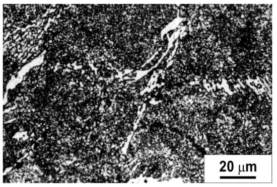
Figure 7.
Microstructure of high-speed steel HS 6-5-2-5 (LM).
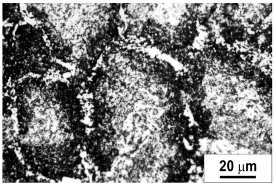
Figure 8.
Microstructure of high-speed steel HS 6-5-2C (LM).
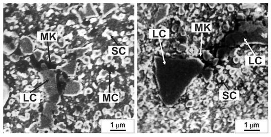
Figure 9.
Microcavities (MC) and microcracks (MK) on ledeburite (LC) and secondary carbides (SC) (SEM).
During the discussion about the cutting of high-speed steel, the formation of the built-up edge (BUE) was mentioned (Figure 10). This phenomenon is the product of several effects, among which the following stand out: processes of diffusion of certain chemical elements of the base material of the tool or workpiece, and then the process of adhesion of the surface and removal of protective coatings, temperature, compressive stresses and other secondary effects. It should also be noted that the appearance of deposits is mainly related to multiphase materials. When one wants to give a description of BUE, it must be emphasized that it consists of non-cohesive elements that are bonded to each other due to pressure forces. The BUE represents highly deformed layers of complex structures with the presence of cavities, which grow over time and accelerate the separation of the deposit. The BUE appears in the frequency interval that is affected by a large number of the previously mentioned effects.
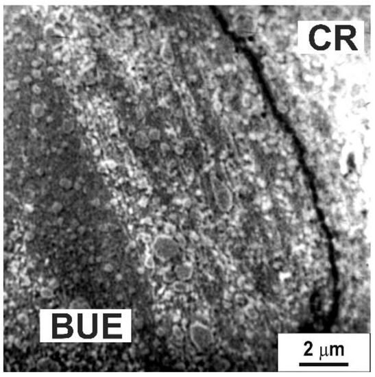
Figure 10.
Formation of built-up edge (BUE) on the tool (CR–chip root material) (SEM).
The complex microstructure of Ti3SiC2 ceramics in etched conditions, obtained on the light microscope, is shown in Figure 11. The microstructure consists of the Ti3SiC2 matrix (main phase), with a small amount of TiC particles and around 5% of porosity. When performing the experiment, it is necessary to make an adequate choice for the processing parameters. If favorable regimes are not determined under which the material is removed from the ceramics, the powder form of the chips may appear, that is, the root of the chips may not be visible (Figure 12). However, if attention is paid and precise processing is carried out, this primarily means ensuring the stability and rigidity of the sample; with adequate processing parameters, a visible protrusion representing the chip root can be obtained (Figure 13 and Figure 14).
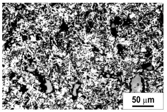
Figure 11.
Microstructure of Ti3SiC2 ceramic (LM).
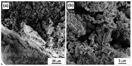
Figure 12.
(a) Chip root step on the workpiece and (b) powder-like chip during machining of Ti3SiC2 ceramic (SEM).
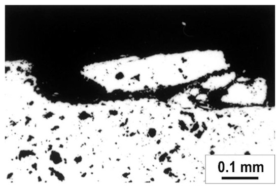
Figure 13.
Cross section of chip root of Ti3SiC2 ceramic in polished conditions; for cutting conditions v = 0.93 m/s, f = 0.446 mm/t and a = 4.4 mm (LM).
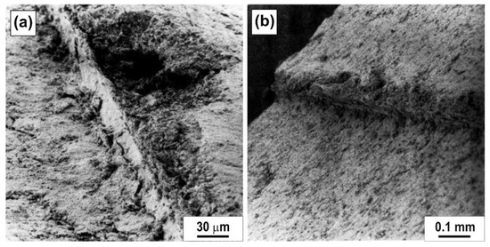
Figure 14.
Chip roots of Ti3SiC2 ceramic (SEM); for cutting conditions: (a) v = 1.18 m/s, f = 0.220 mm/t and a = 3.8 mm; (b) v = 0.93 m/s, f = 0.279 mm/t and a = 3.8 mm.
In the primary cutting zone of the Ti3SiC2 ceramic workpiece specimens, fracture appears without previous plastic deformation. The fracture initiates in the primary shear zone and propagates towards the chip free surface. However, the fracture was not only present in the primary and secondary shear zone, but the fracture split-off was observed in the uncut surface of the chip root samples as a consequence of the tool high pressure (Figure 14).
In addition, as in the case of high-speed steel, the appearance of microcavities which formed in the Ti3SiC2 ceramics chip was recorded, which can be seen from Figure 15. This phenomenon also contributes to a more intensive breakage of the chip in the ceramic.
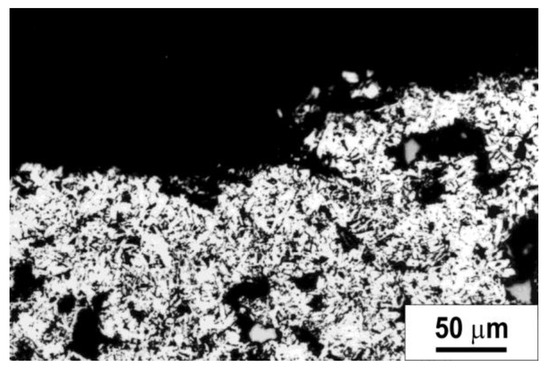
Figure 15.
Cross-section of the root of a Ti3SiC2 ceramic chip in the etched state (LM).
There are different qualifications that define the shape of the chip as well as the formed root [30,31]. On the basis of the literature sources about the chip root, it is established that lamellar chips are formed in high-speed steels and ceramics as well. In the case of high-speed steel, there is a tendency towards a continuous-cut shape of the chip, while in the case of ceramic materials, there is a more pronounced tendency towards the classic discontinuous shape of the broken chip.
The Cutting Ratio (or chip thickness ratio) factor was measured on some samples of the high-speed steel and was in the range of (λ = 5 ÷ 6°), which falls out of the range of good machinability. For ceramics, it was not possible to measure this factor, and accordingly, no emphasis was placed on researching this type of machinability.
Table 3 shows the components of cutting forces during Ti3SiC2 ceramic processing for one procedure. The measurement was performed using the measurement acquisition system shown in Figure 3.
Table 3.
Measured components of cutting forces during cutting of Ti3SiC2 ceramics.
In the case of the acquisition of the Fx, Fy and Fz cutting force components, the transfer of the component is as follows: Fc—main cutting force, Fr—radial force component and Fp—force component propagating the Fa—axial force component, defined through Equations (3)–(6), illustrated in the scheme in Figure 16. Fc (the main cutting force) is the most representative force for analysis [32].
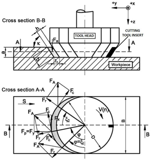
Figure 16.
The connection between the orthogonal components (Fx, Fy) and the cutting forces (Fc, Fp, Fr), as a function of time (t), i.e., angle ϕ.
Figure 17 shows an example of the appearance of orthogonal components of the cutting force pattern Fx, Fy and Fz, per one revolution of one tooth milling tool, with machining high-speed steel workpiece versus time for the presented constant cutting conditions.
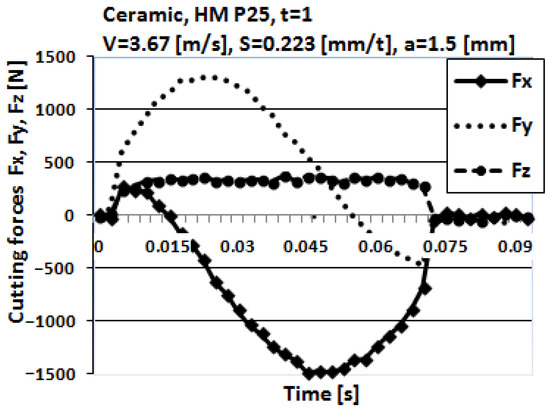
Figure 17.
Orthogonal components of cutting force patterns of one tooth per revolution.
Figure 18 shows the influence of cutting speed on the main cutting force component Fc for both materials machined in the study. The main cutting force component Fc increases very slowly in contrast to the cutting speed for the high-speed steels, while for the ceramic, it remains approximately constant.
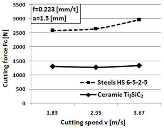
Figure 18.
Relation between cutting speed and main cutting force component Fc.
The influence of feed on the main cutting force component Fc for both materials machined is shown in Figure 19. As shown in Figure 19, the main cutting force component Fc increases more significantly when feed increases for the Ti3SiC2 ceramic.
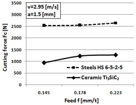
Figure 19.
Relation between cutting feed and cutting force component Fc.
The maximal values of the main cutting force component Fc according to the pattern in Figure 15 and Equation (1) are presented in Figure 18, Figure 19 and Figure 20, for different cutting conditions.
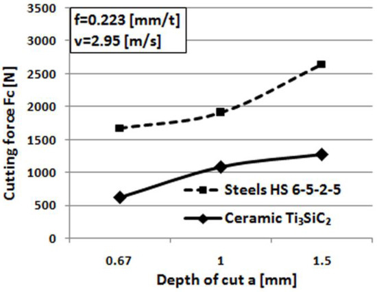
Figure 20.
Relation between the depth of cut and the main cutting force component Fc.
The influence of depth of cut on the main cutting force component Fc for both materials machined is shown in Figure 20. The main cutting force component Fc increases significantly when cutting depth increases for both the machined materials.
The main cutting force component Fc for the Ti3SiC2 ceramic is considerably smaller for all investigated cutting conditions, which verifies that it has better machinability than high-speed steels. This is a great advantage of the Ti3SiC2 ceramic, which is not characteristic for other kinds of ceramic when machining. It is known from the literature that if the cutting force is greater, the machinability of the material is impaired [33,34,35,36].
When we observe the microstructural influence, as well as the processes that occur during the formation of the chip root, it is noted that when the cutting speed is increased, the force increases during the processing of high-speed steel, while this value remains constant in the case of ceramics. This phenomenon can be related to a more intensive deposition process when processing high-speed steel, which is more intensive at higher temperatures due to the adhesion effect on the rake face of the tool. Such a deposit prevents the proper formation of chips and thus affects the size of the cutting force. When the feed and cutting depth are varied, i.e., the surface section of the cutting layer, a brittle material such as ceramics separates in the form of lamellae that are constantly stressed by pressure and sliding in the chip formation zone. Such constant mechanical loading leads to an increase in dynamic cutting forces, which manifests itself in the resulting cutting force shown in the experiment.
5. Conclusions
According to the results of the study, the following conclusions can be summarized.
During the processing of high-speed steels, the chip root with a high-plastic deformation was obtained. The strip shape of the lamella increased its degree of deformation with the growth of the chips. The growth of the chips was interrupted due to breakage in the zones where microcracks were present, which were formed by the coalescence of microcavities. The appearance of microcracks was also recorded in the vicinity of the shear zone. The ledeburite carbides had a significant influence in the chip breaking process. Their appearance in the form of a coarse-grained or fine-grained phase had an impact on the intensity of plastic deformation.
During the Ti3SiC2 ceramic cutting, a powder-like chip was noticed. Visible chip root step on the workpiece was noticed and fracture appeared without previous plastic deformation in the primary and secondary cutting zones. However, the fracture was not only present in the primary and secondary shear zone, but the fracture split-off was observed in the uncut surfaces of the samples as a consequence of the high tool pressure influence.
The main cutting force component Fc remained approximately constant when cutting speed increased and significantly increased when the feed and depth of cut increased, for both machined high-speed steels.
The main cutting force component Fc for the Ti3SiC2 ceramic was considerably lower, which verifies that ceramic has a better machinability than high-speed steels and this is a great advantage of Ti3SiC2 ceramic machining properties.
Author Contributions
B.S. participated in the calculations for the designed experiment, analyzed the results, wrote and edited. P.K. conceptualized the research, perfected the method for obtaining the experimental samples and contributed to the writing. L.S. analyzed the metallographic samples and contributed to the discussion. D.R. prepared the metallographic samples, performed imaging on the SEM microscope, and participated in writing, edit and visualization. All authors gave their comments on the presented results of the article. All authors have read and agreed to the published version of the manuscript.
Funding
This research received no external funding.
Data Availability Statement
Not applicable.
Acknowledgments
The authors are grateful to M. W. Barsoum from The Department of Materials Engineering, Drexel University, USA, for providing the Ti3SiC2 samples used in this study.
Conflicts of Interest
The authors declare that they have no conflict of interest.
References
- Merchant, M.E. Mechanics of the metal cutting process. I. Orthogonal cutting and a type 2 chip. J. Appl. Phys. 1945, 16, 267–275. [Google Scholar] [CrossRef]
- Kronenberg, M. Machining Science and Application: Theory and Practice for Operation and Development of Machining Processes (First English Ed.); Pergamon Press: Oxford, UK, 1966; p. 53. [Google Scholar]
- Aurich, J.; Bil, H. 3D finite element modelling of segmented chip formation. CIRP Ann. 2006, 55, 47–50. [Google Scholar] [CrossRef]
- Shuang, F.; Chen, X.; Ma, W. Numerical analysis of chip formation mechanisms in orthogonal cutting of Ti6Al4V alloy based on a CEL model. Int. J. Mater. Form. 2018, 11, 185–198. [Google Scholar] [CrossRef]
- Arrazola, P.; Barbero, O.; Urresti, I. Influence of material parameters on serrated chip prediction in finite element modeling of chip formation process. Int. J. Mater. Form. 2010, 3, 519–522. [Google Scholar] [CrossRef]
- Lv, D.; Zhang, Y. Numerical simulation of chipping formation process with smooth particle hydrodynamic (SPH) method for diamond drilling AIN ceramics. Int. J. Adv. Manuf. Technol. 2018, 96, 2257–2269. [Google Scholar] [CrossRef]
- Wang, F.; Tao, Q.; Xiao, L.; Hu, J.; Xu, L. Simulation and analysis of serrated chip formation in cutting process of hardened steel considering ploughing-effect. J. Mech. Sci. Technol. 2018, 32, 2029–2037. [Google Scholar] [CrossRef]
- Nobel, C.; Hofmann, U.; Klocke, F.; Veselovac, D. Experimental investigation of chip formation, flow, and breakage in free orthogonal cutting of copper-zinc alloys. Int. J. Adv. Manuf. Technol. 2016, 84, 1127–1140. [Google Scholar] [CrossRef]
- Bergmann, B.; Denkena, B.; Beblein, S.; Picker, T. FE-Simulation based design of wear-optimized cutting edge roundings. J. Manuf. Mater. Process. 2021, 5, 126. [Google Scholar] [CrossRef]
- Szwajka, K.; Trzepiecinski, T. On the machinability of medium density fiberboard by drilling. BioResources 2018, 13, 8263–8278. [Google Scholar] [CrossRef]
- Komanduri, R.; Hazra, J. A metallurgical investigation of chip morphology in machining an aisi 1045 steel at various speeds up to 10,100 sfpm. In Proceedings of the 9th North American Manufacturing Research Conference Proceedings, University Park, PA, USA, 19–22 May 1981; The Pennsylvania State University: University Park, PA, USA, 1981; pp. 356–373. [Google Scholar]
- Jaspers, S.; Dautzenberg, J. Material behaviour in conditions similar to metal cutting: Flow stress in the primary shear zone. J. Mater. Process. Technol. 2002, 122, 322–330. [Google Scholar] [CrossRef]
- Ueda, K.; Iwata, K.; Nakayama, K. Chip formation mechanism in single crystal cutting of β-brass. CIRP Ann. 1980, 29, 41–46. [Google Scholar] [CrossRef]
- Iwata, K. A Study on Orthogonal Micro Machining of Single Crystal Copper. J. JSPE 1991, 57, 1247. [Google Scholar]
- Weule, H.; Hüntrup, V.; Tritschler, H. Micro-cutting of steel to meet new requirements in miniaturization. CIRP Ann. 2001, 50, 61–64. [Google Scholar] [CrossRef]
- Simoneau, A.; Ng, E.; Elbestawi, M. The effect of microstructure on chip formation and surface defects in microscale, mesoscale, and macroscale cutting of steel. CIRP Ann. 2006, 55, 97–102. [Google Scholar] [CrossRef]
- Simoneau, A.; Ng, E.; Elbestawi, M. Modeling the effects of microstructure in metal cutting. Int. J. Mach. Tools Manuf. 2007, 47, 368–375. [Google Scholar] [CrossRef]
- Ducobu, F.; Rivière-Lorphèvre, E.; Filippi, E. Experimental contribution to the study of the Ti6Al4V chip formation in orthogonal cutting on a milling machine. Int. J. Mater. Form. 2015, 8, 455–468. [Google Scholar] [CrossRef]
- Brocail, J.; Watremez, M.; Dubar, L.; Bourouga, B. Contact and friction analysis at tool-chip interface to high-speed machining. Int. J. Mater. Form. 2008, 1, 1407–1410. [Google Scholar] [CrossRef]
- Gopalsamy, B.M.; Mondal, B.; Ghosh, S.; Arntz, K.; Klocke, F. Investigations on hard machining of Impax Hi Hard tool steel. Int. J. Mater. Form. 2009, 2, 145–165. [Google Scholar] [CrossRef]
- Zhang, Y.; Mabrouki, T.; Nelias, D.; Gong, Y. FE-model for titanium alloy (Ti-6Al-4V) cutting based on the identification of limiting shear stress at tool-chip interface. Int. J. Mater. Form. 2011, 4, 11–23. [Google Scholar] [CrossRef]
- Wang, C.; Xie, Y.; Zheng, L.; Qin, Z.; Tang, D.; Song, Y. Research on the chip formation mechanism during the high-speed milling of hardened steel. Int. J. Mach. Tools Manuf. 2014, 79, 31–48. [Google Scholar] [CrossRef]
- Dargusch, M.S.; Sun, S.; Kim, J.W.; Li, T.; Trimby, P.; Cairney, J. Effect of tool wear evolution on chip formation during dry machining of Ti-6Al-4V alloy. Int. J. Mach. Tools Manuf. 2018, 126, 13–17. [Google Scholar] [CrossRef]
- Klocke, F.; Lortz, W.; Trauth, D. Analysis of the dynamic chip formation process in turning. Int. J. Mech. Sci. 2018, 135, 313–324. [Google Scholar] [CrossRef]
- Shivpuri, R.; Hua, J.; Mittal, P.; Srivastava, A.; Lahoti, G. Microstructure-mechanics interactions in modeling chip segmentation during titanium machining. CIRP Ann. 2002, 51, 71–74. [Google Scholar] [CrossRef]
- Cotterell, M.; Byrne, G. Dynamics of chip formation during orthogonal cutting of titanium alloy Ti–6Al–4V. CIRP Ann. 2008, 57, 93–96. [Google Scholar] [CrossRef]
- Sidjanin, L.; Kovac, P. Fracture mechanisms in chip formation processes. Mater. Sci. Technol. 1997, 13, 439–444. [Google Scholar] [CrossRef]
- Barsoum, M.W.; El-Raghy, T. Synthesis and characterization of a remarkable ceramic: Ti3SiC2. J. Am. Ceram. Soc. 1996, 79, 1953–1956. [Google Scholar] [CrossRef]
- Kovac, P.; Sidjanin, L. Investigation of chip formation during milling. Int. J. Prod. Econ. 1997, 51, 149–153. [Google Scholar] [CrossRef]
- König, W. Fertigungsverfahren 1: Drehen, Fräsen, Bohren. Springer: Berlin/Heidelberg, Germany, 2008. [Google Scholar]
- Kovač, P.; Sidjanin, L.; Rajnović, D.; Savković, B.; Wannasin, J. The microstructure infl uence on the chip formation process of Al-Cu alloy cast conventionally and in semi solid state. Metalurgija 2012, 51, 34–38. [Google Scholar]
- Savković, B.; Kovač, P.; Stoić, A.; Dudić, B. Optimization of machining parameters using the Taguchi and ANOVA analysis in the face milling of aluminum alloys Al7075. Teh. Vjesn. 2020, 27, 1221–1228. [Google Scholar]
- Molaiekiya, F.; Aramesh, M.; Veldhuis, S. Chip formation and tribological behavior in high-speed milling of IN718 with ceramic tools. Wear 2020, 446, 203191. [Google Scholar] [CrossRef]
- Savkovic, B.; Kovac, P.; Dudic, B.; Gregus, M.; Rodic, D.; Strbac, B.; Ducic, N. Comparative Characteristics of Ductile Iron and Austempered Ductile Iron Modeled by Neural Network. Materials 2019, 12, 2864. [Google Scholar] [CrossRef] [PubMed]
- Zhang, X.; Ma, C.; Li, S.; Pan, D.; Zheng, F. Interface design of lead-free free-cutting titanium reinforced graphite brass composites and its effect on mechanical properties and cutting performance. Mater. Sci. Eng. A 2020, 774, 138909. [Google Scholar] [CrossRef]
- Yi, S.; Li, J.; Zhu, J.; Wang, X.; Mo, J.; Ding, S. Investigation of machining Ti-6Al-4V with graphene oxide nanofluids: Tool wear, cutting forces and cutting vibration. J. Manuf. Process. 2020, 49, 35–49. [Google Scholar] [CrossRef]


Disclaimer/Publisher’s Note: The statements, opinions and data contained in all publications are solely those of the individual author(s) and contributor(s) and not of MDPI and/or the editor(s). MDPI and/or the editor(s) disclaim responsibility for any injury to people or property resulting from any ideas, methods, instructions or products referred to in the content. |
© 2023 by the authors. Licensee MDPI, Basel, Switzerland. This article is an open access article distributed under the terms and conditions of the Creative Commons Attribution (CC BY) license (https://creativecommons.org/licenses/by/4.0/).